

Page 1
1
High Speed Transducer
Thank You
Thank you for choosing Humminbird®, America’s #1 name in fishfinders. Humminbird® has
built its reputation by manufacturing top-quality, thoroughly reliable marine equipment.
Genuine Humminbird® accessories offer the opportunity to upgrade and expand the
capabilities of your Humminbird® product.
NOTE: Your transducer may not look exactly like the transducer shown in the
illustrations, but it will mount in exactly the same way.
About Transom Mount Installation
There are a number of ways to install a transducer on your boat. The transom mount
installation provides the least loss of signal since the transducer is mounted outside the boat
hull. This installation also allows adjustment of both running angle and depth after the
transducer is mounted, which enables you to tune the installation for best results. Also, the
mounting hardware is designed to pivot the transducer body out of the way should the boat
strike debris in the water, or when trailering. All necessary hardware is included for this type
of installation.
Before You Start
Following are instructions for the installation of the High-Speed Transducer. We encourage
you to read these instructions carefully to get full benefit from your Humminbird® accessory.
If you find that any items are missing from your installation kit, contact our Humminbird®
Customer Resource Center at 1-800-633-1468 or visit our website at www.humminbird.com.
In addition to the hardware supplied with your transducer, you will need a powered hand drill
and various drill bits, Phillips and flat head screwdrivers, a ruler or measuring tape, pen or
pencil, and silicone sealant.
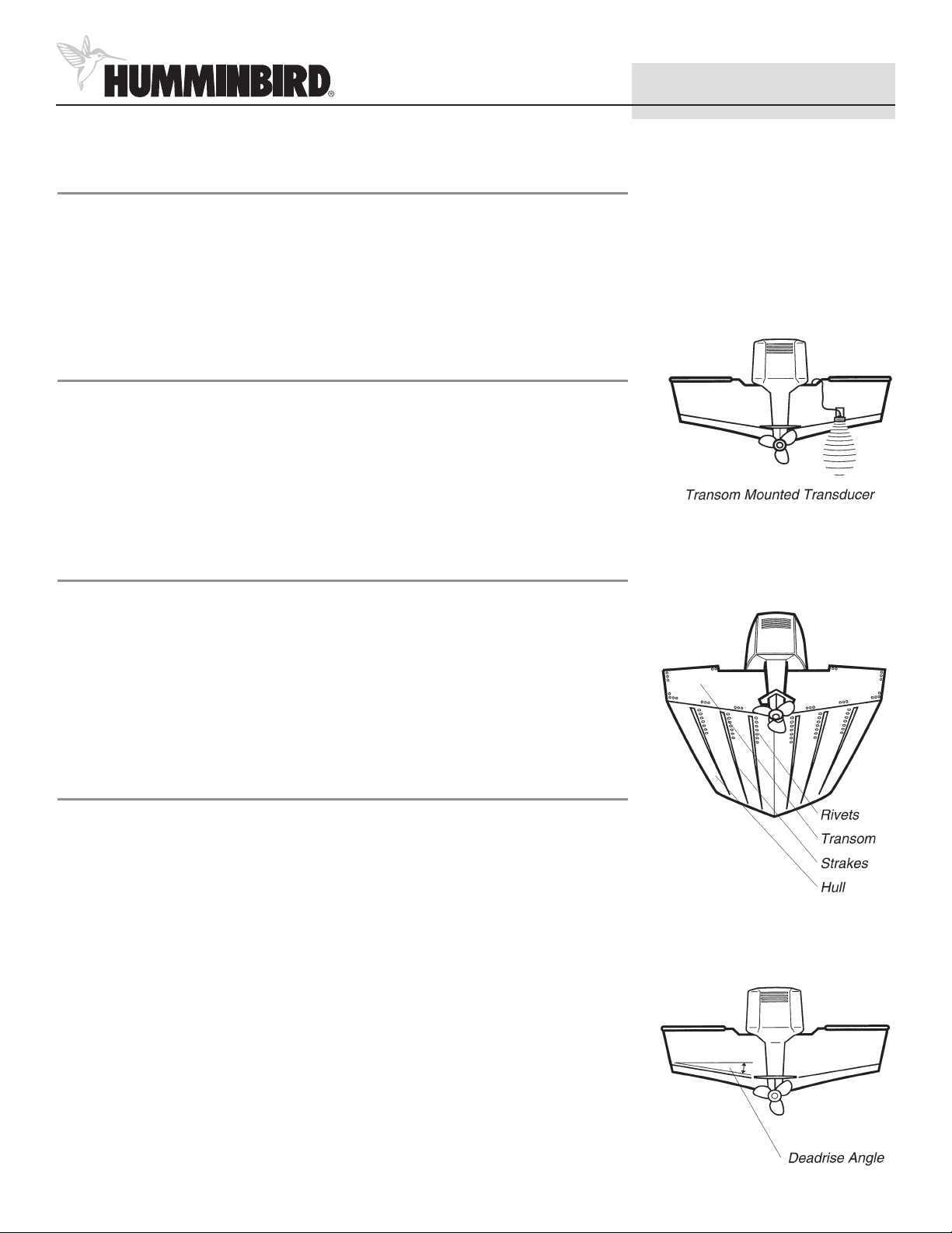
Locating the Transducer
As a boat moves through the water, turbulence is generated by the weight of the boat and
the thrust of the propeller(s). This turbulent water is normally confined to areas immediately
aft of ribs, strakes, or rows of rivets on the bottom of the boat, and in the immediate area of
the propeller(s). It is very important to locate the transducer in an area of relatively
turbulence-free water. If the propeller(s) are forward of the transom, it may be impossible to
find an area clear from turbulence, and a different mounting technique should be considered.
If possible, viewing the transom of the boat while the boat is moving will provide the best
means of locating clear water, and if maximum high-speed operation is a high priority, this is
the recommended method. If this is not possible, select an area on the transom where the
hull forward of this location is smooth and free of protrusions or ribs.
Another consideration is the angle of deadrise. The transducer, when mounted, should point
straight down. The design of the transducer will allow a deadrise of 15 degrees while
remaining pointed straight down. If the deadrise is greater than 15 degrees it will be
necessary to angle the transducer slightly. While this does not significantly degrade
performance, you must keep in mind that the area you are viewing on your fishfinder screen
may be somewhat to one side of the boat.
Page 2
2
High Speed Transducer
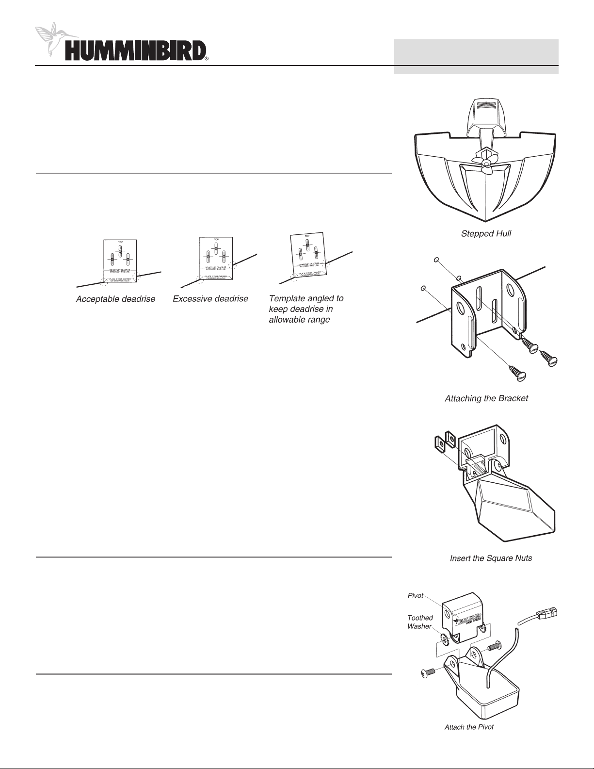
On boats with stepped hulls, it may be possible to mount the transducer on the step. Never
mount the transducer on the transom behind a step, as this area of the transom will not be
in contact with the water at high speeds.
Mounting the Bracket
Once you have identified the location, use the mounting template from the last page of these
instructions. This template serves two purposes: it provides a means of ensuring that the
deadrise of the transom falls within allowable limits, and it locates the three mounting holes
which must be drilled.
Hold the template on the transom of the boat in the location you have selected. Align the
template vertically, ensuring the lower edge of the transom on either side of the template
falls within the horizontal lines on the template. If not, tilt the template slightly so that the
lower edge of the transom on both sides of the template fall within the allowable range.
Using a pencil or a punch, mark the three mounting holes onto the transom. Using a 5/32”
(4 mm) bit, drill the three holes to a depth of approximately 1” (25 mm).
NOTE: On fiberglass hulls, it is best to use progressively larger drill bits to reduce the
chance of chipping or flaking the outer hull coating.
Use a silicone sealant to fill the drilled holes, especially if the holes penetrated the transom wall.
Align the metal mounting bracket with the mounting holes. The center slot should be above
the two outer slots. (This bracket and all other hardware supplied is top quality stainless steel
for maximum strength and corrosion protection). Insert the three 1” (25 mm) flat head wood
screws into the drilled holes, but do not completely tighten.
Assembling the Transducer
Attach the pivot to the transducer body as shown in the following illustration using the two
1/4--20 x 5/8” (16 mm) machine screws, toothed washers, and square nuts. The toothed
washers must fit on the inside of the transducer ears, between the pivot and the ears. The
square nuts will be prevented from rotating by the pocket in the back of the pivot.
An Allen wrench is provided which fits all of the 1/4--20 screws, but do not fully tighten the
screws at this time.
Attaching the Transducer
Slide the assembled transducer into the metal bracket from the bottom, aligning the large
hole at the top of the bracket with the hole in the pivot.
Insert the headed pin through the pivot holes in the bracket and pivot. The headed pin can
be inserted from either side of the bracket.
Page 3

3
High Speed Transducer
Place the nylon washer over the opposite end of the headed pin. Place the stainless
washer over the 1/4--20 x 5/8” screw threads, then insert into the opposite end of
the headed pin and finger tighten only. The screw has a thread locking
compound on the threads to prevent loosening, and should not be fully
tightened until all adjustments are made.
Running Position Adjustment
The running position of the transducer is now completely adjustable. Subsequent
adjustment may be necessary to tweak the installation after high speed testing. The
metal bracket allows height and tilt adjustment; the pivot screws allow angle adjustment.
Adjust the angle of the transducer body first, so it is parallel with the hull of the boat, and fully
tighten the two pivot screws using the supplied Allen wrench. Access to the pivot screws is
provided by the lower holes in the side of the mounting bracket.
Next, adjust the height of the assembly so the face of the transducer is 1/8” (3 mm) to 1/4”
(6 mm) beneath the bottom of the transom, and fully tighten the three mounting screws.
In order to gain access to the mounting screws, the transducer assembly must be pivoted up
into the bracket as shown. Be careful not to alter the running angle as some force is necessary
to pivot the assembly.
If access to the top mounting hole is not possible due to the selected height of the transducer,
fully tighten the two lower screws. Remove the headed pivot pin and the transducer
assembly, tighten the top screw, and then reassemble.
Finally, ensure that all mounting screws are fully tightened.
Routing the Cable
The transducer cable has a low-profile connector that must be routed to the point where the
fishfinder is mounted. Every boat is different and there may be several ways to route the
cable (see the illustration on the following page).
If you choose to pass the cable through the transom of the boat, a 5/8” (16 mm) hole must
be drilled above the waterline. Fill this hole with silicone sealant, and use the supplied
escutcheon plate to dress the entry hole. This will require two #8 x 5/8” (16 mm) screws and
drilled holes of 9/64” (3.6 mm).
Remember that the transducer can pivot 90 degrees in the bracket should an object be struck,
and make sure sufficient cable slack exists for this movement. It is best to route the cable to
the side of the transducer so the cable will not be damaged by the rotating transducer.
Cable clamps are provided to secure the cable to the transom, and use the same type of
screws as the escutcheon plate.
Inside the boat, there is often a channel or conduit which is used for other wiring, which can
be used to route the transducer cable forward. Avoid routing the cable in areas where it may
be damaged or may interfere with normal boating operations. The transducer cable should
not be cut or shortened, and care should be used not to damage the cable insulation. Also,
be sure to route the cable as far as practical from the antenna cable of VHF radios to reduce
the possibility of interference.
Attaching the pivot to the bracket
Tighten the Pivot Screws
Tighten the Mounting Screws
Hand Tighten Only
Page 4

4
High Speed Transducer
This accessory works with a number of Humminbird® fishfinder products. Some products
may require disassembly of the fishfinder mounting bracket in order to connect the cable.
Refer to your operations manual and/or control head installation sheet for the correct
procedure for routing cables and cable connections.
If you find that the cable is too short for your application, extension cables are available
at a reasonable cost which can extend the transducer cable up to 50’ (15 m). Contact the
Humminbird® Customer Resource Center at 1-800-633-1468 or visit our website at
www.humminbird.com.
Maintenance
If your boat remains in the water for long periods of time, algae and other marine growth
can reduce the effectiveness of the transducer. Periodically clean the face of the
transducer with liquid detergent. Pivoting the transducer up in the bracket may allow
better access for inspection or cleaning.
In some cases it may take some time to wet the transducer when returned to the water.
Small air bubbles can cling to the surface of the transducer and can interfere with proper
operation. These bubbles will dissipate with time, or you may wipe the face of the
transducer with your fingers after the transducer is in the water.
Customer Support
Your Humminbird® accessory is designed for trouble-free operation and is backed by the
same one-year warranty as our fishfinders, VHF Marine-band radios, and GPS Navigation
equipment. Refer to your Humminbird® product operations manual for the specific
details of this warranty. If you have any questions, contact the Humminbird® Customer
Resource Center at 1-800-633-1468 or visit our website at www.humminbird.com.
Throughout the US and Canada, our hours are Monday through Friday, 8:00 a.m. to
4:30 p.m., Central Standard Time.
Humminbird
678 Humminbird Lane
Eufaula, AL 36027
www.humminbird.com
530506-2_A
 Loading...