

Page 1
SC 110 Autopilot
Installation and Operations Manual
SC 110 Autopilot
Installation and Operations Manual
531760-3_A
Page 2
i
Thank You
Thank you for choosing Humminbird®, the #1 name in Fishfinders.
Humminbird® has built its reputation by designing and
manufacturing top-quality, thoroughly reliable marine equipment.
Your Humminbird® accessory is designed for trouble-free use in
even the harshest marine environment. In the unlikely event that
your Humminbird® accessory does require repairs, we offer an
exclusive Service Policy - free of charge during the first year after
purchase, and available at a reasonable rate after the one-year
period. For complete details, see the separate warranty card
included with your accessory. We encourage you to read this
operations manual carefully in order to get full benefit from all the
features and applications of your Humminbird® product.
Contact our Customer Resource Center at 1-800-633-1468 or visit
our Web site at humminbird.com.
WARNING!
It is the operator’s responsibility to make prudent decisions
regarding personal safety and the operation of the vessel. Do
NOT leave the autopilot unattended while it is steering the vessel.
Watch for obstacles and potential hazards at all times. Be
prepared to respond to changing conditions and take manual
control of the vessel as required.
WARNING!
The autopilot system should be installed by a Certified Marine
Electronics Technician (CMET) or an authorized Marine
Electronics Installer (MEI). See NMEA.org for details. Incorrect
installation affects the system's performance, which affects the
safety of the vessel and its passengers. If you have questions
about the installation, please contact our Customer Resource
Center.
WARNING!
This device should not be used as a navigational aid to prevent
collision, grounding, boat damage, or personal injury. When the
boat is moving, water depth may change too quickly to allow time
for you to react. Always operate the boat at very slow speeds if
you suspect shallow water or submerged objects.
Page 3
ii
WARNING!
Do NOT use the autopilot where there may be shallow water,
obstacles, or when manual navigation is required, especially in the
following situations:
• while navigating or maneuvering in shallow waters or
dangerous seabeds,
• while entering or exiting harbor, mooring, or setting sail,
• while traveling at high speed,
• in heavy traffic areas, near breakwaters, canals,
• or while encountering any potential obstacles.
WARNING!
While you are learning to use the autopilot, it is important to
practice in calm, open sea, far from shallow water, vessels, or
other obstacles.
WARNING!
When you first power up the autopilot, confirm that the bearing
of the compass on the screen matches the vessel’s analog
compass reading. If there is a significant difference between the
readings, contact an authorized technician (CMET or MEI), or
contact the Humminbird® Customer Resource Center for
assistance.
WARNING!
This product contains chemicals known to the State of
California to cause cancer and/or reproductive harm.
WARNING!
Disassembly and repair of this electronic unit should only be
performed by Humminbird® authorized service personnel. Any
modification of the serial number or attempt to repair the original
equipment or accessories by unauthorized individuals will void
the warranty.
NOTE:
We recommend that you read this manual completely so you
understand the installation and operation requirements before
you proceed. Keep this manual with you on the vessel for your
reference.
Page 4

iii
NOTE:
Product specifications, features, and printed materials are subject
to change without notice. Humminbird® is not responsible for any
direct or indirect damage that may occur to people, animals, or
things due to the use of its products.
NOTE:
Some of the features described in this manual require a separate
purchase. Every effort has been made to clearly identify those
features. Please read the manual carefully in order to understand
the full capabilities of your model.
NOTE:
To purchase accessories and additional equipment for your
control head, visit our Web site at humminbird.com or contact
our Customer Resource Center at 1-800-633-1468.
NOTE:
The procedures and functions described in this manual are
subject to change without notice. This manual was written in
English and may have been translated to another language.
Humminbird® is not responsible for incorrect translations or
discrepancies between documents.
Humminbird® is a registered trademark of Johnson Outdoors Marine
Electronics, Inc.
© 2012 Johnson Outdoors Marine Electronics, Inc. All rights reserved.
Page 5

iv
About the SC 110 Autopilot 1
Installation 2
Connecting the Control Head to the CPU . . . . . . . . . . . . . . . . . . . . 2
Connecting the TC 110 Joystick
(optional-purchase required). . . . 3
Dashboard Mount . . . . . . . . . . . . . . . . . . . . . . . . . . . . . . . . . . . . . . . . . . . 4
Control Head 7
Power On/Off 8
Control Head Configuration (initial setup only) 9
Start Installation Mode . . . . . . . . . . . . . . . . . . . . . . . . . . . . . . . . . . . . . . 9
Input Installation Settings . . . . . . . . . . . . . . . . . . . . . . . . . . . . . . . . . . 10
Operating Parameters Wizard . . . . . . . . . . . . . . . . . . . . . . . . . . . . . . 16
Compass Settings . . . . . . . . . . . . . . . . . . . . . . . . . . . . . . . . . . . . . . . . . . 18
Test the Autopilot and Finalize Installation 19
Test 1: Confirm Autopilot Equipment & Readouts . . . . . . . . . . . . 19
Test 2: Confirm Autopilot Performance on the Water. . . . . . . . 22
Test 3: Compass Automatic Compensation
and Readout Confirmation . . . . . . . . . . . . . . . . . . . . . . . . . . . . . . . 22
Using the Autopilot 24
Operation Modes: Introduction 24
Multisensor Technology 26
Default Display 28
Wind Display (optional-purchase Wind Sensor required) 30
Table of Contents
Page 6

Table of Contents
Navigate with the Autopilot 32
Standby Mode . . . . . . . . . . . . . . . . . . . . . . . . . . . . . . . . . . . . . . . . . . . . . 32
Bow Targeting
(Auto or Auto-Track mode) . . . . . . . . . . . . . . . . . . . . 34
Auto Turn
(Auto mode, Compass required) . . . . . . . . . . . . . . . . . . . . 36
Follow-Up Mode
(Follow-Up mode) . . . . . . . . . . . . . . . . . . . . . . . . . . 38
Dodge
(optional-purchase TC 110 Joystick required; Auto mode,
Auto-Track mode, Nav mode only) . . . . . . . . . . . . . . . . . . . . . . . . . . . . 39
Navigate with Humminbird® Multi-Function Display
(Nav mode,
chartplotter [optional-purchase], and Humminbird® GPS required). 40
Wind Navigation
(Sailboat navigation only, Wind Sensor
optional-purchase required). . . . . . . . . . . . . . . . . . . . . . . . . . . . . . . . . . 42
Set the Wind Angle
(Wind mode, Wind Sensor required) . . . . . . . 42
Tack or Gybe
(Auto or Wind mode [Wind Sensor required]) . . . . . 43
Manage Control Head Settings 46
Change the Backlight Setting . . . . . . . . . . . . . . . . . . . . . . . . . . . . . . 46
Switch the Active Compass . . . . . . . . . . . . . . . . . . . . . . . . . . . . . . . . 47
Reset to Factory Settings . . . . . . . . . . . . . . . . . . . . . . . . . . . . . . . . . . 48
Change the Autopilot Settings
(Authorized Technicians only) . . . . . . . . . . . . . . . . . . . . . . . . . . . . . . . 49
Alarms 52
Specifications 55
Customer Service 57
v
Page 7

About the SC 110 Autopilot
The SC 110 autopilot uses multisensor technology and operation
modes to provide steering control for any type of vessel. The
control head provides graphic and numeric readouts of the
course, heading, and rudder movement. If a wind sensor is
installed, the apparent wind will be displayed in Wind mode.
There are many available operation modes which allow you to
bow target, choose turn patterns, tack and gybe, or navigate a
route from an optional-purchase Humminbird® Multi-Function
Display. The autopilot system requires specific optional-purchase
accessories to enable each of the operation modes. Contact our
Customer Resource Center for more information.
We encourage you to read this manual carefully so that you may
understand the full capabilities of the SC 110 autopilot.
1
About the SC 110
Page 8

Installation
The SC 110 Autopilot includes hardware and a template to mount
the control head in the dashboard. You may also purchase gimbal
mount hardware and extension cables for your installation.
Contact our Customer Resource Center for details.
The SC 110 Autopilot control head connects to the SCP 110 Course
Computer (CPU) so that it receives input from the Fluxgate
Compass, Gyronav Rate Sensor, GPS receiver, and all connected
autopilot equipment.
WARNING!
The CPU and all related equipment should be
installed by a Certified Marine Electronics Technician
(CMET) or an authorized Marine Electronics Installer
(MEI). See NMEA.org for details.
1. Connecting the Control Head to the CPU
1. Turn off the power to the CPU.
2. Test route the power cable from the CPU to the
autopilot control head.
3. Remove the CPU cover and insert the cable through
the CPU strain relief for the correct terminal, and
proceed as follows:
• Unit 1 (TB7): Remove the terminated block from
the TB7 Control Unit 1 connector. Insert the bare
wires of the Power/CPU cable into the terminated
block connector as shown in Inserting the Wires
into the Terminated Block.
• Unit 2 (TB8): If you are connecting a second
autopilot (optional-purchase Remote SC 110
Control Head), remove the terminated block from
the TB8 Control Unit 2 connector. Insert the bare
wires of the Power/CPU cable into the terminated
block connector as shown in Inserting the Wires
into the Terminated Block.
2
Installation
Page 9
4. Tighten the wire connections and slide the terminated
block back into the connector.
5. Replace the cover on the CPU.
6. Route the power cable to the control head. You will
connect the power cable to the control head in a later
step.
2. Connecting the TC 110 Joystick
(optional-purchase required)
1. Follow the installation instructions included with the
joystick.
2. Route the accessory cable to the control head. You
will connect the accessory cable to the control head
in a later step.
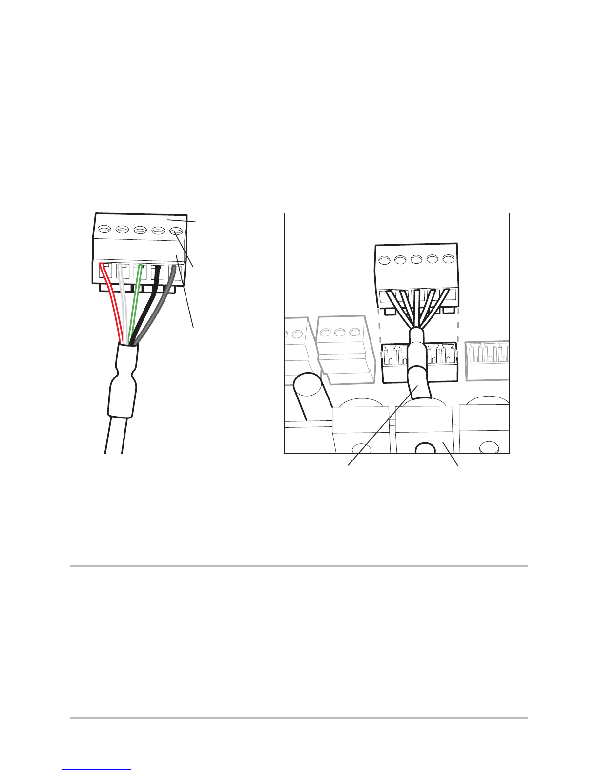
1 2 3 4 5
Inserting the Wires into
the Terminated block
Sliding the Terminated
Block into the CPU
Wiring Order
1- red
2- white
3- green
4- black
5- drain
Terminated
Block
Tighten wire
connections
Cable threaded
through strain relief
Strain
Relief
3
Installation
Page 10

4
Installation
3. Dashboard Mount
Your SC 110 autopilot includes hardware to mount the control
head in the dashboard.
NOTE:
You may also purchase Gimbal mount hardware
and extension cables for your installation. Contact
the Humminbird® Customer Resource Center for
more information.
1. Choose a suitable, flat area of the dashboard to
mount the control head, noting the following
requirements:
• Control head depth: 3 inches (7.6 cm).
• The area should be protected from waves, shock,
and water.
• The area should be easily accessible for all cables
to reach the control head.
2. Tape the paper In-Dash Mounting template to the
mounting location you choose. Make sure the
template is level.
3. At a location inside the dotted line on the template,
drill a hole large enough to insert the blade of a
reciprocating saw. Carefully begin cutting toward the
dotted line, and then follow the dotted line around the
template. Remove the template when finished.
Page 11
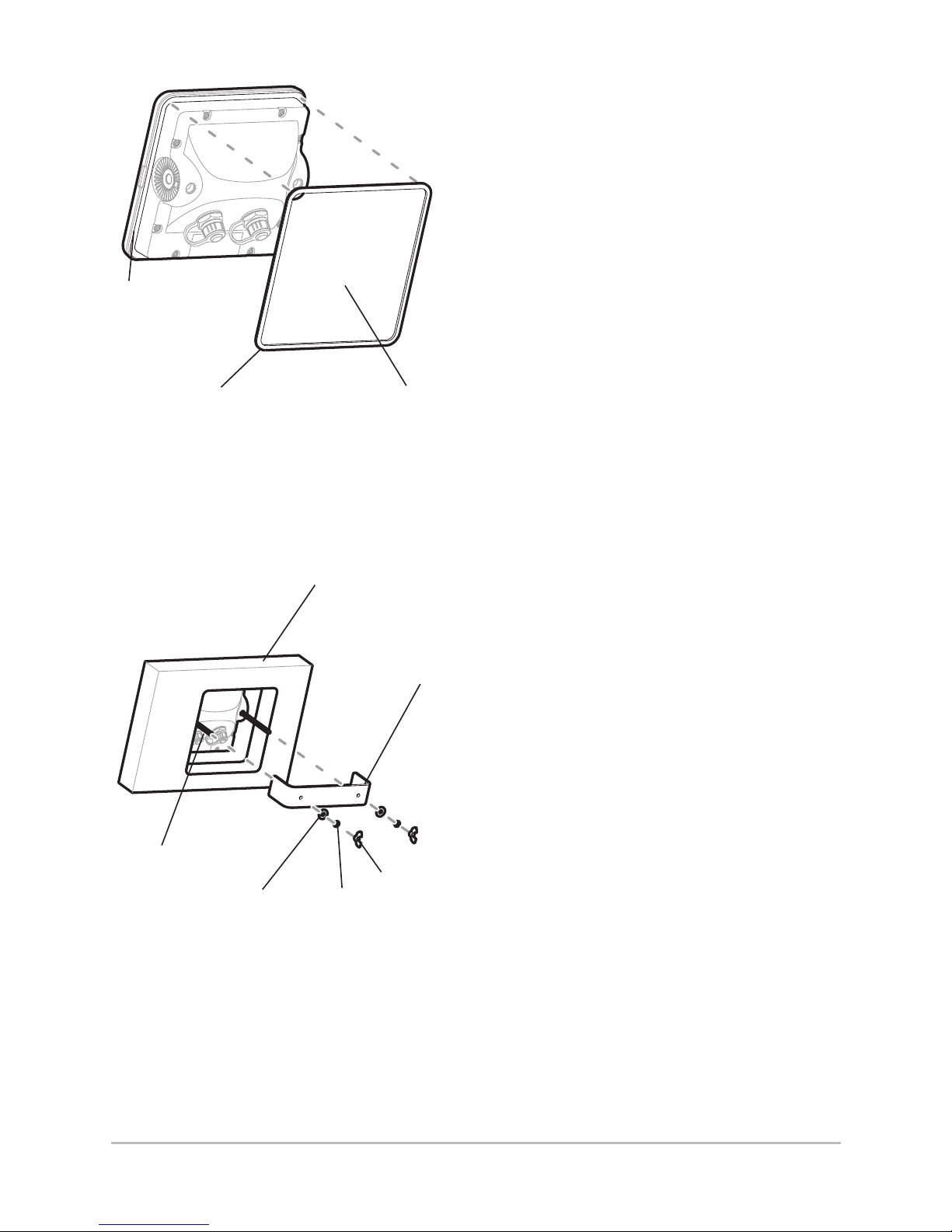
4. If the gasket has a foam
center, remove the center.
5. Peel off the liner of the
adhesive side of the
gasket. Place the gasket’s
adhesive side on the rim
on the back of the control
head.
6. Insert and tighten the
two threaded rods into
the two threaded
inserts located on the
back of the control
head (see Attaching
the Bracket).
7. Peel off the second liner
from the gasket, and
insert the control head
through the mounting
hole from the front side
of the dashboard.
8. Slide the bracket onto the
two threaded rods.
9. Place a flat washer onto
each threaded rod, and
then secure the bracket
by placing a lock
washer and wing nut
onto each threaded rod.
Hand tighten only.
Do not overtighten the
wing nuts.
Attaching the Bracket
Threaded
Rod
Flat
Washer
Bracket
Wing Nut
Lock
Washer
Dashboard
(partial view)
Attaching the Foam Pad
Gasket
Rim
Hollow
Center
5
Installation
Page 12

6
Installation
10. On the back of the autopilot control head, insert the
power cable into the POWER/CPU port, and if
purchased, insert the TC 110 Joystick cable to the
ACCESSORY port.
NOTE:
The connectors are keyed to prevent incorrect
installation, so be careful not to force the
connectors into the wrong ports.
11. Hand-tighten the screw nuts on each cable connector
to secure. Proceed to Control Head Configuration to
set up the Autopilot for initial use.
Page 13
7
Control Head
Control Head
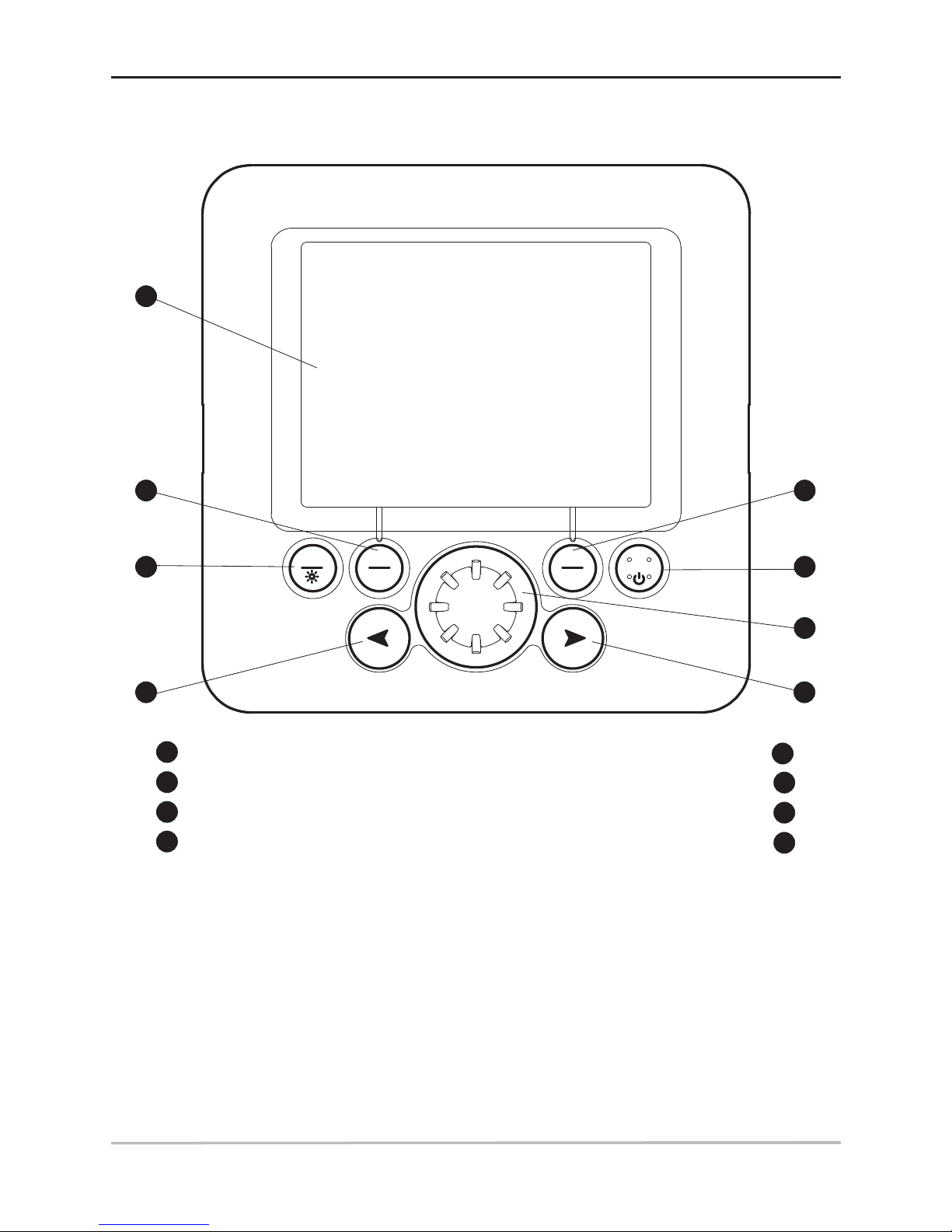
The keys on the autopilot control head allow you to access various
operation modes and menu settings.
AUTO/TRACK key
AUTO
TRACK
STANDBY
SET
T
URN
NAV
Screen
STANDBY/POWER key
1
6
NAV/TURN key
Rotary Knob
2
7
SET/BRIGHT key
RIGHT ARROW key
3
8
4
3
5
6
7
8
1
2
LEFT ARROW key
4
5
Page 14

Power On/Off
Use the following instructions to power on/off the autopilot
control head.
Power On
1. Press the STANDBY/POWER key.
2. The splash screen will display while the autopilot
transitions to Standby mode. The splash screen
displays the current control head and CPU software
versions.
Power Off
Press and hold the STANDBY/POWER key until the control
head powers off.
8
Power On/Off
Page 15
Control Head Configuration (initial setup only)
The control head configuration is required for initial operation of
the autopilot. After these menus have been set, Installation mode
should only be used periodically.
WARNING!
The menus in this section affect the autopilot
operation, which affects the safety of the vessel and
its passengers. If you do not understand a menu
function, do NOT change the setting. Contact the
Humminbird® Customer Resource Center for
assistance.
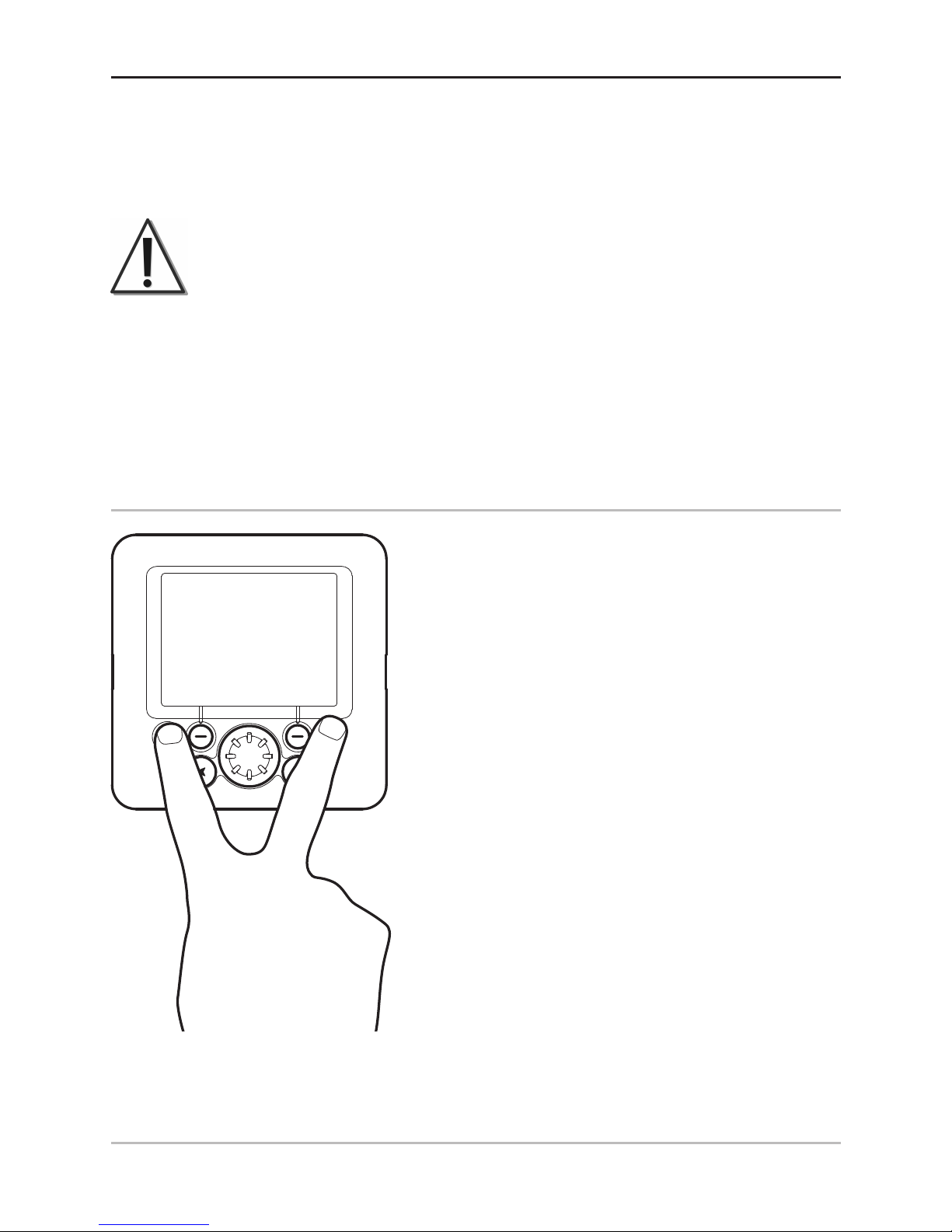
1. Start Installation Mode
To start Installation Mode, use the
following steps:
1. Power on the control head.
2. Press and hold the SET/BRIGHT
key and the STANDBY/POWER
key at the same time.
3. INSTALLATION will be
displayed at the top right
corner of the screen.
AUTO
TRACK
TURN
NAV
9
Control Head Configuration
Page 16
2. Input Installation Settings
There are several installation settings available for the autopilot,
and the default settings are suitable for many vessels. Each menu
setting is important and must be accurate for maximum autopilot
performance.
• Connected Equipment: It is important to enable
devices that are connected to the autopilot control
head and CPU, such as the compass, rudder system,
and attached accessories.
• Compass Models: For more information about how to
enable various compass types, see Section 4,
Compass Settings.
• Alarms: Set the Rudder Alarm or the Off Course Time
Out in the Installation Mode.
• Expansion Cards: When an expansion card is installed
in the CPU, the corresponding settings will be added to
the Installation Mode menu, and you must enable
additional attached equipment (such as a
GyroCompass).
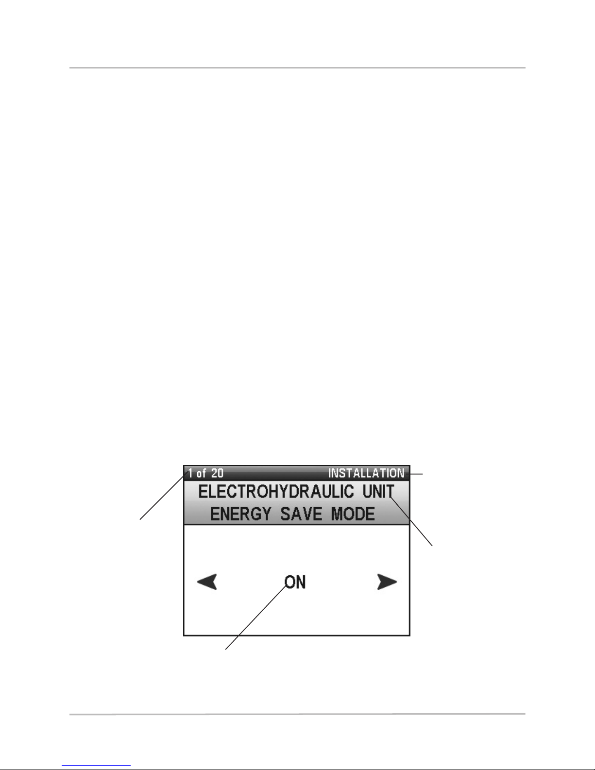
Setting Installation Menus
Number of
available
menus
and the
order in
the queue
Installation
Mode
Current
Menu
Menu Setting:
Turn Rotary Knob or press ARROW
keys to change settings.
10
Control Head Configuration
Page 17

11
Control Head Configuration
WARNING!
The menus in this section affect the autopilot
operation, which affects the safety of the vessel
and its passengers. If you do not understand a
menu function, do NOT change the setting.
Contact the Humminbird® Customer Resource
Center for assistance.
To scroll through menu options: Press the SET/BRIGHT key.
To change menu settings: Press the RIGHT ARROW key or
LEFT ARROW key to adjust the first menu option. You can
also use the Rotary Knob to change the settings. The
setting will be saved automatically.
To return to the first Installation Mode Menu: Press the
SET/BRIGHT key and the STANDBY/POWER key.
To exit Installation Mode: Press the STANDBY/POWER key.
Menu Description Settings
Language Sets the language for
the display.
English: English
Italiano: Italian
Francais: French
Español: Spanish
Deutsch: German
Default: English
Units – Speed Sets the units of
measure for speed
readouts.
kts: knots
mph: miles per hour
km/h: kilometers per hour
Default: kts
Units – Distance Sets the units of
measure for distance
readouts.
nm: nautical miles
sm: statute miles
km: kilometers
Default: nm
Magnetic Compass
Signal Strength
Reports the strength
of signal reception.
N/A: system readout
Rudder Limit Sets the maximum
angle (port and
starboard) that the
autopilot can move
the rudder.
10° to 35°
Default: 25°
Page 18

12
Menu Description Settings
Feedback Slack Sets the allowable
tolerance or dead
band before the
system will respond
to changes in
feedback. Reduces
servo jitter or chatter.
.5° to 3.0°
Where .5 = tighter response to
rudder feedback, and 3.0 =
looser response to rudder
feedback.
Default: .7°
Feedback 0
Position
Adjusts the zero (0)
position of the rudder
when there is a
dierence between
the actual rudder
position and the
readout on the
display. Make sure
the rudder is in the
center position before
you change this
setting.
-7.5° to 7.5°
(where -7.5 = Port and
+7.5 = Starboard)
Default: 0°
Feedback Type Sets the rudder
feedback type
connected to the
autopilot. The
Gyronav sensor must
be connected and
enabled (see
Gyronav).
Disabled: O
FB30
LF n: Linear Normal
LF r: Linear Reverse
POT n: Potentiometer Normal
POT r: Potentiometer Reverse
LIN: Linear
Default: FB30
Power Steering
Type
Sets the type of the
power steering
actuator installed on
the vessel. Pump
should be matched to
steering cylinder size.
Rev 2 and Rev 3
settings attenuate
controller voltage
output.
SOL: Solenoids
(valve actuators)
REV 1: Pump is well matched
to steering cylinder (100%
controller voltage output)
REV 2: Oversized pump (80%
controller voltage output)
REV 3: Grossly oversized
pump (60% controller voltage
output)
RELAYS: Signal level outputs
for interfacing with vessel
steering systems.
Control Head Configuration
Page 19

13
Menu Description Settings
Energy Save Turns the energy save
mode on or o.
Enable this setting to
prevent the steering
system from running
when it is not
required. This feature
is useful on sailboats
only when a Solenoid
Power Pack is
installed.
Disabled: O
Enabled: On
Default: Disabled
Rudder Alarm Sets whether the
rudder alarm will
sound due to an error
in the rudder
movement.
Enabled: On
Disabled: O
Standby: This setting is not
recommended for all vessels.
If there is a rudder movement
error, the autopilot will
disengage and enter Standby
mode automatically. Be
prepared to manually control
the vessel.
Default: Enabled
Magnetic Compass
Type
Sets the compass
model connected to
the autopilot CPU.
FXC110: Humminbird® FXC110
HRS1: Humminbird® HRS1
Default: FXC110
Compass Alignment Adjusts the electronic
compass reading so
that the compass
doesn’t have to be
moved to receive
accurate readings.
-30° to 30°
Default: 0°
NOTE: Adjust this setting after
the Compass Compensation
procedure has been
performed.
Compass Damping Adjusts the filter
setting to prevent
sensitivity to
intermittent signals.
Controls oscillation
of the compass
reading.
0 to 9
Default: 6
Control Head Configuration
Page 20

14
Menu Description Settings
NAV2 Function Sets the function of
the equipment
connected to NAV2 in
the CPU.
Disabled: O
Nav2: Chartplotter (#2)
Wind: Wind Sensor
Default: Wind
O Course Timeout Sets the amount of
time (in seconds)
before the o course
alarm will begin to
sound or display on
the screen when the
vessel has moved
more than 20° o
course.
Disabled: O
10s to 120s
Default: 30s (30 seconds)
Info Display Sets the GPS readout
displayed on the right
side of the screen.
SOG: Speed Over Ground
COG: Course Over Ground
Tiller Control
Function
Auto mode only.
Adjusts the rudder
setting from the tiller
control function.
Standard: Temporary Dodge
1° to 30° (Adjusts the heading
by the set amount)
Default: Standard
Minimum Rudder Sets the value (in
degrees) that the
autopilot will add to
any given rudder
command. This
feature can make the
vessel more
responsive to
autopilot commands,
especially when it
does not respond to
small deflections of
the rudder because of
its mid-ship position
(e.g. waterjet
propulsions).
0.0° to 3.0°
Default: 0.0°
Control Head Configuration
Page 21

Menu Description Settings
Multisensor Enables or Disables
the Multisensor mode
(Fluxgate compass,
GPS, and Gyronav).
Gyronav sensor must
also be connected
and enabled.
Enabled: On
Disabled: Off
Default: Disabled
Gyronav Enables or Disables
the Gyronav
connected to the
CPU. The Gyronav
setting must be used
with the Fluxgate
Compass (FXC 110).
Enabled: On
Disabled: Off
Default: Enabled
15
Control Head Configuration
Page 22

3. Operating Parameters Wizard
The Operating Parameters Wizard will automatically calculate the
measurements for the Yaw, Rudder, Counter Rudder, and Turn Rate
for the vessel. These settings may also be adjusted manually (see
Manage Control Head Settings: Change the Autopilot Settings).
1. From Installation mode (see Control Head
Configuration: Start Installation Mode), press and hold
the NAV/TURN key. Operating Parameters Wizard will
be displayed in the top right corner of the screen.
To scroll through menu options: Press the
Set/BRIGHT key.
To change menu settings: Press the RIGHT ARROW
key or LEFT ARROW key to adjust the first menu
option. You can also use the Rotary Knob to adjust
the settings. The setting will be saved automatically.
To exit Operating Parameters Wizard: Press the
STANDBY/POWER key.
Operating Parameters Wizard
16
Control Head Configuration
Page 23

2. Enter the following information into the Operating
Parameters Wizard:
• HULL TYPE: Set the vessel’s hull type.
DISPLACEMENT
(power boat, displacement hull)
PLANING (power boat, planing hull)
WATERJET (waterjet propulsion system)
SAILBOAT (sail boat)
• LENGTH: Set the vessel’s length.
• MAXIMUM SPEED:
Set the vessel’s maximum speed.
3. Follow the menu prompts and adjust the settings to
match your vessel information until you reach the final
screen, “SAVE SETTINGS?” Press the RIGHT ARROW
key to save settings, or press the LEFT ARROW key to
discard settings.
4. After the settings are saved, the yaw, rudder, counter
rudder, and turn rate will be set automatically.
5. To exit, press the STANDBY/POWER key.
Save
Settings
Discard
Settings
Saving or Discarding Settings
17
Control Head Configuration
Page 24

4. Compass Settings
The autopilot system is compatible with a variety of compass
models. See the CPU installation guide for details. To enable each
compass in the Installation mode menu, use the guidelines in the
table below.
One heading sensor can be used at a time. To switch between the
magnetic compass and the GyroCompass, see Manage Control
Head Settings: Switch the Active Compass.
NOTE:
There are additional steps to configure the
compass with the Autopilot control head. See
Test the Autopilot and Finalize Installation for
details.
Compass Model Confirm Installation Mode Settings
Humminbird® FXC 110 and
Gyronav® rate sensor
Magnetic Compass Type = FXC110
Gyronav = Enabled
Humminbird® HRS1 Magnetic Compass Type = HRS1
GyroCompass
(optional-purchase
expansion card required)
Expansion Card – GyroCompass Type =
enter the appropriate value (see
GyroCompass installation guide)
18
Control Head Configuration
Page 25

Test the Autopilot and Finalize Installation
After installation and configuration are complete, it is important to
test the autopilot for accuracy and performance. You will also
compensate the compass and confirm the compass settings. It is
important to complete all the steps in this section.
WARNING!
If the equipment is not functioning properly, or the
display readout is not correct, contact an
authorized technician (CMET or MEI), or contact
our Customer Resource Center for assistance.
Test 1: Confirm Autopilot Equipment & Readouts
The first test should be performed while the vessel is anchored in
a safe harbor or at dock.
1. Power on the control head.
2. Press the POWER/STANDBY key to begin Standby
Mode. Confirm the following sensor settings:
Rudder Feedback Unit
1. Turn the wheel of the rudder manually.
2. Confirm that the rudder angle matches the angle
displayed on the screen.
If the angle displayed on the screen is the
opposite angle of the actual rudder setting, see
the installation guides for the rudder feedback
sensor and CPU to invert the wire connections
for the feedback connector (pin 3 and 4).
TC 110 Joystick (optional-purchase)
1. Adjust the rudder angle with the remote control.
2. Confirm that the rudder angle matches the angle
displayed on the screen. If the angle displayed on
19
Test the Autopilot
Page 26

the screen is the opposite angle of the actual
rudder setting, see the installation guides for the
TC 110 Joystick, the Rudder Feedback, and the
CPU to invert the wire connections.
Fluxgate Compass
1. Compare the compass readout on the screen
with the vessel’s main magnetic compass.
Confirm that the compass is providing a reading.
You will compensate the compass and confirm the readout
again in Test 3: Compass Automatic Compensation and
Readout Confirmation.
Electrohydraulic Unit
1. Move the rudder to the center manually.
2. Press the AUTO/TRACK key once to enter Auto
mode, and enter a 10 or 20 degree course
change by turning the Rotary Knob.
3. Confirm that the rudder moves in the correct
direction. If the rudder moves in the opposite
direction, see the installation guides for the CPU
and the installed rudder steering system to
determine how to invert the right and left
solenoids (power unit with the solenoids) or invert
the wires of the motor (reversing power unit).
Humminbird® GPS (required)
and/or Chartplotter
(optional-purchase)
For proper communication between the Humminbird® GPS
or Humminbird® Multi-Function Display (MFD) and the
Autopilot control head, the Humminbird® MFD must be set
to ouput NMEA 0183, which is typically the default setting.
20
Test the Autopilot
Page 27

NOTE:
The autopilot can receive input from 2 satellite
devices maximum. For example, they can be
installed on the main deck or flying bridge. See
your chartplotter, GPS receiver, and CPU
installation guides for details.
To confirm that the chartplotter is enabled
:
1. On the autopilot control head, press the
NAV/TURN key to enter Navigation mode.
2. Set a route on the Humminbird® MFD and start
navigation.
3. Confirm that the bearing on the Humminbird®
MFD matches the bearing on the autopilot
control head.
To confirm that the GPS receiver is connected
:
When a Humminbird® GPS is connected to the CPU,
you will see the GPS icon displayed on the screen in
Auto-Track mode.
1. On the autopilot control head, press and hold the
AUTO/TRACK key to enter Auto-Track mode.
2. Confirm that the GPS icon is displayed on the
screen. If the icon is not displayed, see the
installation guides for the GPS receiver and the
CPU to confirm the installation.
Wind Direction Sensor (optional-purchase)
1. Confirm that the wind sensor is connected
properly to the CPU and that WIND is enabled in
the Installation Mode, NAV2 menu.
2. Press the NAV/TURN key twice to enter Wind mode.
3. Confirm that the wind bearing displayed on the
screen is correct. If it is not correct, see the wind
sensor guide to confirm installation.
21
Test the Autopilot
Page 28

22
Test the Autopilot
Test 2:
Confirm Autopilot Performance on the Water
After Test 1 is completed, check the settings and equipment again
while in open sea.
WARNING!
While you are learning to use the autopilot, it is
important to practice in calm, open sea, far from
shallow water, vessels, or other obstacles.
Test 3: Compass Automatic Compensation
and Readout Confirmation
Use Compass Automatic Compensation to measure and
automatically offset compass magnetic interference. It may also
be necessary to run Compass Automatic Compensation if you
have trailered the vessel to a new location that might have
different magnetic zones.
WARNING!
Compass Automatic Compensation should be
performed at slow speed, in calm, open sea, in a
large area that is far from shallow water, vessels,
or other obstacles.
1. From Installation mode,
press and hold the
AUTO/TRACK key.
2. Steer the vessel in a
circle, noting the
following:
Settings & Speed: The
rudder should maintain a
constant setting (within 5
to 15°), and it should take
1 - 2 minutes to complete
the turn.
Page 29

Wait: You may have to
steer the vessel so it
completes 2 or 3
complete circles. The
screen will display “Wait”
during this procedure.
3. When the procedure
is complete, the screen
will display SUCCESS or
FAILED. If the procedure
was successful, press the
STANDBY/POWER key
to exit.
Adjust: If the compass
setting must be tweaked
slightly to match the
analog compass, see the
Compass Alignment
setting in Control Head
Configuration: Input
Installation Settings.
If the procedure failed: The compass might be installed in a
location with too much magnetic interference. Check the compass
location and possible magnetic disturbances in the area.
4. Confirm the Compass Reading: Compare the compass
reading on the screen with the vessel’s main magnetic
compass.
If there is a big difference in the readings: Check the
compass installation location, or turn it on its vertical
axis until the difference is cancelled. Zero the compass
setting and follow the steps in the Automatic Compass
Compensation section.
23
Test the Autopilot
Page 30

Using the Autopilot
After an authorized marine technician has installed the control
head and equipment, configured the control head, and then
tested all equipment, the autopilot may be used in open water.
Operation Modes: Introduction
The autopilot has several operation modes that allow the autopilot
to steer the vessel. Operation modes are also determined by the
optional-purchase equipment connected and enabled in the
autopilot system. You will learn how to apply each operation
mode on the following pages.
WARNING!
Do NOT leave the autopilot unattended while it
is steering the vessel. Watch for obstacles and
potential hazards at all times. Be prepared to
respond to changing conditions and take manual
control of the vessel as required.
WARNING!
As you choose a new operation mode or type of
navigation, the autopilot may make adjustments
to the vessel’s heading to successfully navigate
the vessel. The vessel may turn automatically, and
booms on sailboats may change direction quickly.
It is important to monitor transitions and be
aware of your surroundings.
WARNING!
If the autopilot is not following commands, or the
boat makes sudden, unpredictable movements,
press the STANDBY/POWER key to take manual
control of the vessel. Contact an authorized
technician (CMET or MEI) or our Customer
Resource Center to confirm the installation and
autopilot settings. If erratic behavior persists,
remove the power to the CPU.
24
Operation Modes
Page 31

The autopilot navigation modes are briefly described here.
Proceed to Navigate with the Autopilot for more information.
• Standby: (Press the STANDBY/POWER key) During
Standby mode, the autopilot is not controlling the
vessel. Be prepared to control the vessel manually
before initiating Standby mode.
• Auto: (Press the AUTO/TRACK key) Auto mode uses a
compass to navigate towards the set heading. You can
also choose a turn pattern and tack (with an optionalpurchase wind sensor) in Auto mode. A compass must
be connected to the autopilot system. See Bow
Targeting for more information.
• Auto-Track: (Press and hold the AUTO/TRACK key)
Also known as True Course, Auto-Track mode uses a
Humminbird® GPS receiver to navigate. It is more
accurate than Auto mode because it compensates for
wind and drift to keep the vessel on a straight line
course towards the heading you set. A GPS receiver
must be connected to the autopilot system. See Bow
Targeting for more information.
• Nav: (Press the NAV/TURN key) Nav mode allows you
to enter a route on an attached Humminbird® MultiFunction Display or chartplotter. The autopilot will
follow the route or any changes you make from the
MFD. The MFD overrides the autopilot control head in
this operation mode, so the ARROW keys and Rotary
Knob are unavailable in Nav mode. A chartplotter and
Humminbird® GPS must be connected to the autopilot
system.
• Follow Up: (Press and hold the Rotary Knob) Follow Up
mode allows you to steer the vessel with the autopilot
control head’s Rotary Knob. The Rotary Knob controls
the vessel’s rudder position from Follow-Up mode.
• Wind: (Press the NAV/TURN key twice) Wind mode
allows the autopilot to detect the apparent wind across
the bow of the vessel. You can set the wind angle, as
well as tack or gybe from Wind mode. A wind sensor
must be connected to the autopilot system.
25
Operation Modes
Page 32

26
Multisensor Technology
Multisensor Technology
Your SC 110 Autopilot uses multisensor technology. Several
sensors can be connected to the autopilot system, and you can
select the active sensor. The attached sensors also determine
which operation modes are available on the autopilot system. The
Gyronav Rate Sensor is always active when it is attached to the
system.
Multisensor Icon: When an M is displayed above the active sensor
icon on the screen, Multisensor mode has been enabled.
In Standby mode, the autopilot will automatically switch to the
best available sensor. The autopilot will use the magnetic compass
and Gyronav Rate Sensor at low speed (under 4 kts), and it will
use the GPS receiver and Gyronav Rate Sensor at high speed
(over 4 kts).
In Auto, Auto-Track, Nav, and Wind mode, the active sensor is
displayed on the screen, but the active sensor does not switch
automatically. If you initiate an operation mode while the vessel is
traveling slower than 4 kts, then the compass sensor will be used
even if the speed is increased. To use the GPS receiver as the
active sensor, travel above 4 kts in Standby mode, and then
initiate the desired operation mode.
Magnetic Compass Icon with
Multisensor Enabled or Disabled
Indicates
Multisensor
enabled
Magnetic
Compass
only
Page 33

NOTE:
If a black-out of the GPS receiver occurs, the
autopilot will maintain the set course by using the
compass as back-up.
Sensor Alarms: If a sensor is unavailable, the system will display
an alarm. For example, if the vessel is traveling slower than 4 kts
in Auto-Track mode, the GPS icon will flash on the screen to
indicate that the GPS COG (Course Over Ground) is not as
accurate as the compass. In this case, you should switch to Auto
mode.
See Control Head Configuration: Input Installation Settings to
enable Multisensor mode.
27
Multisensor Technology
Page 34

Default Display
The screen display shown here is shown when Standby, Auto,
Auto-Track, Nav, and Follow-Up mode are active.
12
10
16
11
14
15
17
13
9
1
2
3
4
5
6
7
8
28
Default Display
Page 35

12
10
16
11
14
15
17
13
9
2
3
4
5
6
7
8
Heading: Red line indicates the heading of the vessel on the analog
compass.
Compass: Analog
Operation Mode: Indicates the current operation mode.
Starboard icon: This icon will flash to indicate when the control head
requires a tack direction.
Information Display: SOG (Speed Over Ground) or COG (Course Over
Ground) will be displayed here. See Control Head Configuration to
choose the readout setting.
Big Digits: Displayed information changes with the operation mode. In
Standby or Follow-Up mode, the Heading (HDG) is displayed. In Auto,
Auto-Track, or Nav mode, the Set Course (CRS) is displayed.
Alarm Icons: Icons will be displayed here to indicate an error or failure
with the autopilot system. See also Alarms Text and the Alarms section
of this manual for more information.
Bar Graph Unit Setting: Displays units of measure related to the
heading, rudder position, or XTE (Cross Track Error)
Bar Graph: The information displayed here changes with the operation
mode. In Auto mode, Heading is displayed. In Standby or Follow-Up
mode, the Rudder position is displayed. In Auto-Track or Nav mode, the
XTE is displayed.
Heading, Rudder Position, or XTE indicated on the bar graph.
Alarm Icons: see #7 above.
Active Sensor: Displays the active sensor providing the reading for the
display.
Multisensor: When the “M” is shown on the screen, it indicates that
Multisensor is enabled.
Big Digits Indicators: Indicates the information displayed by the Big
Digits. Heading (HDG) or Course (CRS) will be displayed on the left,
and Magnetic (M) or True North (T) will be displayed on the right.
Heading (Digital Readout): True North, Magnetic North
Port Icon: This icon will flash to indicate when the control head requires
a tack direction.
Alarm Text: Information will be displayed here to provide an error or
failure with the autopilot system. See also Alarm Icons and the Alarms
section of this manual for more information.
1
29
Default Display
Page 36

Wind Display (optional-purchase Wind Sensor required)
Wind mode has a special layout on the screen that represents the
apparent wind and set wind across the bow of the vessel.
NOTE:
Optional-purchase Wind Sensor required.
Contact our Customer Resource Center for more
information.
12
10
16
11
14
15
17
13
9
1
2
3
4
5
6
78
18
30
Wind Display
Page 37

31
Vessel Icon
Operation Mode: Indicates the current operation mode.
Heading (Digital Readout): True North, Magnetic North
Information Display: Speed Over Ground (SOG) or Course Over
Ground (COG).
Set Wind Angle digital readout
Apparent Wind Angle digital readout
Alarm Icons: Icons will be displayed here to indicate an error or failure
with the autopilot system. See also Alarm Text, and the Alarms section
of this manual for more information.
Starboard Icon: This icon will flash to indicate when the control head
requires a tack/gybe direction.
Bar Graph: Shows units of measure related to the heading, rudder
position, or XTE (Cross Track Error)
Heading, Rudder Position, or XTE indicated on the bar graph.
Port Icon: This icon will flash to indicate when the control head requires
a tack/gybe direction.
Alarm Icons: Icons will be displayed here to indicate an error or failure
with the autopilot system. See also Alarm Text, and the Alarms section
of this manual for more information.
Wind Gauge
Apparent Wind Angle: Indicates the direction of wind across the vessel.
Set Wind Angle
Active Sensor: Displays the active sensor providing the reading for the
display.
Multisensor: When the “M” is shown on the screen, it indicates that
Multisensor is enabled.
Alarm Text: Information will be displayed here to provide an error or
failure with the autopilot system. See also Alarm Icons and the Alarms
section of this manual for more information.
12
10
16
11
14
15
17
13
9
1
2
3
4
5
6
7
8
18
Wind Display
Page 38

Navigate with the Autopilot
There are many ways to navigate with the autopilot. It is important
to consider the equipment attached to the autopilot system, the
vessel speed, and the navigation intention.
WARNING!
It is always important to monitor the vessel and
your surroundings while using the autopilot. The
autopilot does not detect land mass or obstacles.
If you need to take manual control of the vessel,
press the STANDBY/POWER key. Make sure you
are fully prepared to manually control the vessel.
Standby Mode
During Standby mode, the autopilot is not controlling the vessel.
Use Standby mode to move the rudder with the ARROW keys on
the control head or with the Humminbird® TC 110 Joystick
(optional-purchase). The Rotary Knob is not available in Standby
mode.
1. To begin Standby mode: Press the STANDBY/POWER
key.
2. To move the rudder: Press the LEFT ARROW key or
RIGHT ARROW key to move the rudder angle port
and starboard respectively.
POWER STEER will flash in the top, right corner of the
screen while you make adjustments with the ARROW
keys or optional-purchase TC 110 Joystick.
Multisensor: If Multisensor is enabled, the autopilot
will automatically switch between the attached
Compass and GPS receiver as needed. See
Multisensor Technology for more information.
WARNING!
You must be fully prepared to manually control
the vessel before you initiate Standby mode.
32
Navigation
Page 39

33
Standby
Mode
Rudder
Position
Heading
Multisensor
enabled
Active
Sensor:
Magnetic &
Gyronav
Autopilot in Standby Mode
Power
Steer
Rudder
Position
Heading
Power Steer from Standby Mode
Multisensor
enabled
Active
Sensor:
Magnetic &
Gyronav
Navigation
Page 40

34
Bow Targeting (Auto or Auto-Track mode)
In Bow Targeting, the autopilot maintains the bow towards the
heading you choose. You can bow target in Auto mode or AutoTrack mode.
The attached equipment and the travel speed influence which
mode you should use. The active sensor will be displayed on the
screen (see Multisensor Technology).
Auto Mode: (compass required) The autopilot uses
compass data to keep the vessel at the selected heading.
Wind, current, or other conditions may cause the vessel to
drift off course.
Auto-Track Mode: (GPS and travel speed above 4 kts
required) Also known as True Course, the autopilot uses
GPS data to keep the vessel at the selected heading.
Auto-Track mode compensates for wind, current, and
other conditions to keep the vessel on course.
WARNING!
Do NOT leave the autopilot unattended while it
is steering the vessel. Watch for obstacles and
potential hazards at all times. Be prepared to
respond to changing conditions and take manual
control of the vessel as required.
Auto-Track
Mode
XTE
(Cross-Track Error)
Course
Multi-
sensor
Enabled
Active
Sensor:
GPS
Autopilot in Auto-Track Mode
Navigation
Page 41

35
To Bow Target in Auto or Auto-Track Mode:
1. Be prepared to manually control the vessel, and then
press the STANDBY/POWER KEY.
2. Move the rudder manually so that the bow is pointing
toward your chosen heading or target.
3. Move the rudder manually so that it is centered and
the vessel can begin navigation in a straight line.
4a. Start Navigation in Auto Mode: Press the
AUTO/TRACK key. Navigation will begin immediately.
Adjust Heading: Turn the Rotary Knob slowly or
press the LEFT or RIGHT ARROW keys. The
Digital Compass will update to show your setting.
Each press of the ARROW keys change the
heading in 1° increments. The Rotary Knob
increases the heading change the faster you turn
the Rotary Knob.
WARNING!
Do not turn the Rotary Knob too quickly or press
the ARROW keys repeatedly. Allow the vessel to
transition to the selected heading, and do not
make quick changes, especially at high speed.
4b. Start Navigation in Auto-Track Mode: Press and hold
the AUTO/TRACK key. Navigation will begin
immediately.
Adjust Heading (not available): If you press the
ARROW keys or turn the Rotary Knob to adjust
the heading, the autopilot will change to Auto
mode.
NOTE:
In Auto or Auto-Track mode, you can use the
optional-purchase TC 110 Joystick to temporarily
deviate from the set course. See Dodge for more
information.
Navigation
Page 42

Auto Turn (Auto mode, Compass required)
The Auto Turn feature is available in Auto mode. A compass must
be connected to the autopilot system.
1. Press the AUTO/TRACK key to start Auto mode.
2. Press and hold the NAV/TURN key. TURN will be
displayed in the top, right corner of the screen.
3. Select a turn pattern: Press the SET/BRIGHT key until
the turn pattern you want is selected. You can choose
U-Turn, Circle, or Figure 8.
4. Select the turn direction: To start the selected turn
towards Port, press the LEFT ARROW key. To start the
turn towards Starboard, press the RIGHT ARROW key.
5. The turn pattern will begin immediately, and the type
of turn will be displayed on the top-right corner of the
screen. When the U- turn is completed, the autopilot
will resume Auto mode. The circle and Figure-8
patterns will continue until you input a new command.
To cancel the turn: Press the STANDBY/POWER key.
WARNING!
You must be fully prepared to manually control
the vessel before you initiate Standby mode.
Figure-8U-Turn Circle
36
Navigation
Page 43

37
WARNING!
The turn speed is controlled by the Turn Rate
parameter (see Control Head Configuration:
Operating Parameters Wizard and Manage
Control Head Settings: Change Autopilot
Settings) and the Rudder Offset setting (see
Control Head Configuration: Input Installation
Settings). Contact an authorized technician (CMET
or MEI) or our Customer Resource Center to
adjust these settings.
WARNING!
Do NOT leave the autopilot unattended while it
is steering the vessel. Watch for obstacles and
potential hazards at all times. Be prepared to
respond to changing conditions and take manual
control of the vessel as required.
Choosing a Turn Pattern
1 of 3 turns
available
Turn function
active
U-Turn
highlighted
Press the LEFT
ARROW key or
RIGHT ARROW
key to choose the
turn direction.
Navigation
Page 44

Follow-Up Mode (Follow-Up mode)
Follow-Up mode allows you to steer the vessel using the Rotary
Knob on the control head. It is important to familiarize yourself
with how the Rotary Knob moves the rudder and therefore
changes the vessel heading. Each click of the Rotary Knob
increases the rudder angle in the direction you choose. Do not
turn the knob too quickly. Also, the ARROW keys are unavailable
in Follow-Up mode.
WARNING!
Do not turn the Rotary Knob too quickly. Allow
the vessel to transition to the selected heading,
and do not make quick changes, especially at high
speed.
WARNING!
When you activate Follow-Up mode, you are
controlling the vessel with the Rotary Knob. You
must be fully prepared to manually control the
vessel before you initiate Follow-Up mode.
To steer the vessel in Follow-Up Mode:
1. Press and hold the Rotary
Knob on the control head.
Follow-Up will be displayed in
the top right corner of the
screen.
2. Turn the Rotary Knob to steer
the vessel.
Clockwise: moves the rudder
angle towards starboard.
Counterclockwise: moves the
rudder angle towards port.
To exit Follow-Up mode:
Press the STANDBY/POWER
key and be prepared to take
control of the vessel.
SET
TURN
NAV
Using the Rotary Knob in
Follow-Up Mode
38
Navigation
Page 45

Dodge
(optional-purchase TC 110 Joystick required;
Auto mode, Auto-Track mode, Nav mode only)
Dodge is a temporary deviation from the course or route selected
in Auto, Auto-Track, and Nav mode. You may need to use Dodge
to steer the vessel around an obstacle, away from shallow water,
or away from other danger that the autopilot cannot detect. The
TC 110 Joystick is required for this feature.
1. While navigating in Auto mode, Auto-Track mode, and
Nav mode, move the joystick on the optionalpurchase TC 110 Joystick as needed.
2. The autopilot maintains the current mode but it allows
you to temporarily deviate from the set course. After
the TC 110 Joystick is released, the autopilot will
return to the previous mode and resume navigation.
NOTE:
For more information about the Humminbird® TC
110 Joystick, contact our Customer Resource
Center or see humminbird.com for details.
Follow-Up
Mode
Rudder
Position
Set Course
Active
Sensor
Follow-Up Mode
39
Navigation
Page 46

Navigate with Humminbird®
Multi-Function Display
(Nav mode, chartplotter [optional-purchase],
and Humminbird® GPS required)
The autopilot can be connected to an optional-purchase
Humminbird® Multi-Function Display (MFD) or other optionalpurchase chartplotter. The autopilot will follow any waypoint or
route changes you make on the MFD.
1. Make sure you are prepared to take manual control of
the vessel, and press the STANDBY/POWER KEY.
2. Move the rudder manually so that the bow is pointing
in the direction of the first waypoint.
3. Move the rudder manually so that it is centered and
the vessel can begin navigation in a straight line.
4. On the Humminbird® MFD, select the route or
waypoint to which you want to navigate. Start
navigation from the MFD.
5. On the autopilot control head, press the NAV/TURN
key once to begin navigation. To initiate navigation
from a chartplotter connected to Nav2 in the CPU,
press the NAV/TURN key twice (NAV2 will be
displayed).
• Unavailable Controls: Because the autopilot is
controlled by the settings in the Humminbird®
MFD, the autopilot ARROW keys and Rotary Knob
are unavailable in Nav mode.
• Alarm (No Route Input): Some chartplotters
will pause at each waypoint mid-route or at
the end of the selected route so that you may
provide approval or the next command. When
this happens, the autopilot is waiting for input.
See the chartplotter screen to provide input or
start a new route.
40
Navigation
Page 47

• Dodge: Move the joystick left or right on the
optional-purchase TC 110 Joystick to temporarily
deviate from the set course (see Dodge).
• To exit Nav Mode: Press the STANDBY/POWER key.
WARNING!
Do NOT leave the autopilot unattended while it
is steering the vessel. Watch for obstacles and
potential hazards at all times. Be prepared to
respond to changing conditions and take manual
control of the vessel as required.
WARNING!
When you initiate Standby mode, the autopilot
will stop controlling the vessel. You must be fully
prepared to manually control the vessel before
you initiate Standby mode.
NOTE:
If you have connected more than one chartplotter
to the CPU, the Nav2 Function must be set to
Nav2 in the Installation Mode. See Control Head
Configuration: Start Installation Mode for more
information.
Nav
Mode
XTE
(Cross-Track Error)
Course
Active
Sensor
Nav Mode with Chartplotter Input
41
Navigation
Page 48

Wind Navigation
(Sailboat navigation only, Wind Sensor optional-purchase required)
Wind mode is designed for sailboats. A wind sensor must be
connected to the autopilot system, and Wind must be enabled in
the Installation settings. See Control Head Configuration and Wind
Display for more information.
WARNING!
The vessel will change direction automatically, and
booms may swing with strong force. It is the
operator’s responsibility to make prudent
decisions regarding personal safety and the
operation of the vessel.
NOTE:
The Nav2 function must be set to Wind in
Installation Mode to enable Wind mode. See
Control Head Configuration for more information.
Set the Wind Angle
(Wind mode, Wind Sensor required)
Set Wind allows you to adjust the vessel heading by setting the
wind angle across the bow. The autopilot will be controlled by the
wind direction, and it will follow any change in the wind direction
automatically.
1. Press the NAV/TURN key twice to start Wind mode.
2. Set Wind Angle: Turn the Rotary Knob to move the
blue arrow icon to the desired angle. Navigation will
begin immediately.
On Course: When the Apparent Wind Angle icon and
the Set Wind Angle icon are lined up on the wind
gauge, the vessel is navigating on course.
Adjust: You can continue to change the set wind angle
to adjust the heading by turning the Rotary Knob.
42
Navigation
Page 49

WARNING!
Do not turn the Rotary Knob too quickly. Allow the
vessel to transition to the selected heading, and do
not make quick changes, especially at high speed.
Tack or Gybe
(Auto or Wind mode [Wind Sensor required])
Tacking and Gybing are used to make a single shift in navigation
so that the sailboat can navigate towards a target in relation to
the wind. Tacking navigates the vessel into the wind, and Gybing
navigates the vessel away from the wind. You can set the
tack/gybe angle from Auto mode or Wind mode.
Valid
Tack
Valid
Gybe
Valid
Tack
No
Tack
No
Gybe
Valid
Gybe
30°
90°
120°
150°
155°155°
150°
120°
90°
30°
25° 25°
Heading
Apparent
Wind
Angle Icon
Set the Wind Angle
Turn the
Rotary
knob to
change the
Set Wind
Angle
Wind
Mode
Set Wind
Angle
digital
readout
Apparent
Wind Angle
digital
readout
43
Navigation
Page 50

Tack in Auto Mode
1. Press the AUTO/TRACK key
to begin Auto mode.
2. Press and hold both
ARROW keys.
3. The top left of the screen
will display Tack Angle?.
Turn the Rotary Knob left or
right to set the tack angle.
4. To start the tack/gybe
towards Port, press the
LEFT ARROW key.
To start the tack/gybe
towards Starboard, press
the RIGHT ARROW key.
• The screen will
display a 5 second count
down, and the control head
will beep during the count
down.
• TACKING will be displayed
in the top left corner during
the navigation change.
WARNING!
Watch out for the
swinging boom and
other changing
conditions on the
vessel.
AUTO
TRACK
S
TANDBY
S
ET
T
URN
NAV
Starting Tack/Gybe
in Auto Mode
Setting the Tack Angle
in Auto Mode
Tack Angle
Input
44
Navigation
Page 51

Tack/Gybe in Wind Mode
1. Press the NAV/TURN key twice to start Wind mode.
2. To choose a tack/gybe direction, press the LEFT
ARROW key (Port) or RIGHT ARROW key (Starboard).
3. The top left of the screen indicates Change Tack? or
Change Gybe?. Press the LEFT ARROW key (Port) or
RIGHT ARROW key (Starboard) again to confirm the
tack/gybe direction.
• The screen will display a 5 second count down,
and the control head will beep during the count
down.
• TACKING or GYBING will be displayed in the top
left corner during the navigation change.
NOTE:
If you do not press the ARROW key a second time,
the tack/gybe command will expire, and the
screen will return to Wind mode.
WARNING!
Watch out for the swinging boom and other
changing conditions on the vessel.
Changing Tack in Wind Mode
Change Tack
confirmation
45
Navigation
Page 52

Manage Control Head Settings
Once you are navigating and using your autopilot on the water,
you may need to adjust some of the settings on the control head.
Change the Backlight Setting
Use the following instructions to adjust the backlight setting on
the autopilot control head.
1. Press and hold the SET/BRIGHT key.
2. Press the LEFT ARROW key or RIGHT ARROW key to
decrease or increase the brightness respectively. You
can also turn the Rotary Knob to change the setting.
The setting is saved automatically, and the screen will
return to the previous mode after 5 seconds.
Settings: 1 to 10, where 1 = dim and 10 = brightest
Default = 10
If set to 8, 9, or 10, the key LEDs will turn off.
To Exit: Press the STANDBY/POWER key.
46
Manage Settings
Page 53

Switch the Active Compass
If a magnetic compass and a Gyrocompass are connected to the
autopilot system, you may choose which compass is the active
sensor. Also, see Control Head Configuration: Compass settings
to enable each connected active sensor.
1. From Standby mode, press and hold the SET/BRIGHT
key and the NAV/TURN key at the same time. The
compass icon will flash on the screen.
2. To select the magnetic compass, press the
LEFT ARROW key.
To select the Gyrocompass, press the RIGHT
ARROW key.
3. To exit, and save the compass setting, press the
STANDBY/POWER key.
47
Manage Settings
Page 54

Reset to Factory Settings
The following instructions allow you to return the autopilot to the
factory default settings. If you choose to reset the settings, the
autopilot must be reconfigured. We recommend that you contact
the Humminbird® Customer Resource Center before you proceed
with this command.
CAUTION!
The vessel must be safe at dock if you choose to
reset the autopilot. Do NOT reset the autopilot at
open sea. This command should be used with
caution!
To reset the autopilot to factory default settings
:
1. Press the STANDBY/POWER key.
2. Press and hold the ARROW keys at the same time.
3. DONE will be displayed on the screen if the reset was
successful.
4. Reconfigure the autopilot. See Control Head
Configuration for detailed information.
48
Manage Settings
Page 55

Change the Autopilot Settings
(Authorized Technicians only)
When the autopilot was configured, the yaw, rudder, counter
rudder, and turn rate were automatically calculated using the
Operating Parameters Wizard (see Control Head Configuration:
Operating Parameters Wizard).
WARNING!
The settings in this section will override the
settings created in the Operating Parameters
Wizard. These settings should only be changed by
an authorized technician (CMET or MEI), or
contact our Customer Resource Center for
assistance.
The following instructions demonstrate how to adjust these
settings manually. The settings should be adjusted incrementally.
1. Press the SET/BRIGHT key.
2. Turn the Rotary Knob, or press the RIGHT ARROW
key or LEFT ARROW key, to adjust the first menu
option. The setting will be saved automatically. Press
the SET/BRIGHT key to cycle to the next menu option.
• Saving: The settings are saved automatically.
• Descriptions: The menu options are described on
the following pages.
• To exit: Press the STANDBY/POWER key.
49
Manage Settings
Page 56

WARNING!
If the vessel is traveling at high speed, it is
important to decrease the Turn Rate setting.
In general, these settings should be adjusted
incrementally.
Menu Description Settings
Yaw Sets how far the vessel can deviate from
a course. Increase the setting to allow for
more deviation from the course, and
decrease the setting to keep the vessel
closer to the selected course.
1 to 9
Default = 3
Rudder Adjusts the rudder eciency. In general,
increase the Rudder setting at low speed,
and decrease the Rudder setting at high
speed. See Adjusting the Rudder.
.5 to 5
Default = 3.0
Counter Rudder Adjusts the counter rudder action in
relation to the size of the vessel, which
aects how the vessel stays on course. In
general, use a higher setting (closer to 5)
for large vessels and a lower setting
(closer to 0) for small vessels. See
Adjusting the Counter Rudder.
0 to 5
Default = 1
Turn Rate Turn Rate limits the rudder angle during
turns. Increase the Turn Rate setting for
tighter, faster turns, and decrease the
setting for slower, wider turns.
1 to 20
Default = 10
50
Manage Settings
Page 57

Counter
Rudder
set too Low
Counter
Rudder
set too High
Adjusting the Counter Rudder
Rudder
set too Low
Rudder
set too High
Adjusting the Rudder
If the rudder value is set too high, the vessel will snake
around the selected course. If the rudder value is set too
low, the vessel will have difficulty navigating the course
within reasonable time.
51
Manage Settings
Page 58

Alarms
When there is an error or a failure within the autopilot system, the
autopilot will alert you by displaying an alarm icon and related
text on the screen. The control head will also beep. The following
pages provide details about each type of alarm.
• Audio Alarm: The control head will beep.
• Text Alarm: Text information about the alert is
displayed in the top left corner of the screen.
• Alarm Icon: An icon related to the problem will be
displayed on the lower left or lower right portion of
the screen.
• Alarms On/Off: See Control Head Configuration to
set the Rudder Alarm and the Off Course Time Out.
• Multiple Alarms: The most important alarm will be
shown first, and the succeeding alarms will flash on
the screen.
Alarm
Text
Alarm
Icon
Auto Mode with Alarm Displayed
52
Alarms
Page 59

Icon Alarm Text Description Solution
No Compass Compass signal lost Check compass installation
and connection to the CPU.
No Gyrocompass Gyrocompass signal
lost
Check compass and
Gyrocompass installation
and connection to the CPU.
No Gyronav Gyronav signal lost Check Gyronav installation
and connection to the CPU.
Compass Error Magnetic
Interference
Increase the distance
between the Gyrocompass
and other electromagnetic
devices.
Tiller Failure Tiller failure on the
remote control
O Course The vessel has
traveled o course
from the set route
or heading.
Possible compass
interference. Increase the
distance between the
compass and other
electromagnetic devices.
Check compass installation
and connection to the CPU.
No Wind Input Wind sensor input
lost
Check wind sensor
installation and connection
to the CPU. See the Wind
Sensor manual.
No GPS Input Lack of GPS signal,
GPS has not
calculated the
position, or the data
transmission to the
autopilot has been
deactivated.
See the GPS manual to
review troubleshooting.
Check GPS installation and
connection to CPU.
Contact our Customer
Resource Center. There
may be keys failure or water
inside the remote control.
No Rudder
Feedback
Rudder feedback
signal not received.
Contact an authorized
technician (CMET or MEI)
or our Customer Resource
Center.
53
Alarms
Page 60

Icon Alarm Text Description Solution
B. Presence of air bubbles
in the hydraulic circuit.
Hydraulic circuit discharge
recommended.
No Rudder
Mechanical Failure:
No rudder
movement detected
after commands are
sent to the steering
system. Rudder
response negative.
C. Tighten the mechanical
connection between the
feedback and the rudder
sector to reduce slack.
No Route Input The autopilot is
waiting for the next
chartplotter
command or
chartplotter input
lost.
See Navigate with
Humminbird® MFD for
more information.
Check the connection of
the chartplotter to the
CPU. See the Installation
Mode settings to enable
chartplotter input.
Steering Motor
Overload
Electrical current
over limit.
Low Battery Power source low Charge the battery or
confirm the fused panel
connection.
CPU Overheat Overheating of the
CPU
A. Contact an authorized
technician (CMET or MEI)
or our Customer Resource
Center. Possible failure of
the electro hydraulic unit.
Contact an authorized
technician (CMET or MEI) or
our Customer Resource
Center. Possible short-circuit
on the electro hydraulic unit
or solenoids, or electro
hydraulic unit unsuitable for
the processor box electronic.
Ventilate the area where the
processor box is installed, or
contact our Customer
ResourceCenter. It is possible
the electro hydraulic unit is
unsuitable for the CPU.
54
Alarms
Page 61

Specifications
Display Size (diagonal) . . . . . . . . . . . . . . . . . . . . . . . . . . 9 cm (3.5 in)
Pixel Matrix . . . . . . . . . . . . . . . . . . . . . . . . . . . . . . . QVGA 320 x 240
Display Type . . . . . . . . . . . . . . . . . . . . . . . . . Transmissive Color TFT
Display Colors . . . . . . . . . . . . . . . . . . . . . . . . . . . . . . . . . . . . . . 65,000
Backlight . . . . . . . . . . . . . . . . . . . . . . . . . . . . . . . . . . . . . . . . . . . . . LED
Communication . . . . . . . . . . . . . . . . . . . . . . . . . . . . . NMEA 0183 Bus
IPX Rating . . . . . . . . . . . . . . . . . . . . . . . . . . . . . . . . . . . . . . . . . . . . . . . . .
IP67 Waterproof/Submersible @ 1 m for 30 minutes and dust tight
Control Head Power Supply . . . . . . . . . . . . . . . . . . . . . . . . . . . . CPU
NOTE:
Product specifications and features are subject
to change without notice.
55
Specifications
Page 62

ENVIRONMENTAL COMPLIANCE STATEMENT: It is the intention of Johnson
Outdoors Marine Electronics, Inc. to be a responsible corporate citizen,
operating in compliance with known and applicable environmental
regulations, and a good neighbor in the communities where we make or sell
our products.
WEEE DIRECTIVE: EU Directive 2002/96/EC “Waste of Electrical and
Electronic Equipment Directive (WEEE)” impacts most distributors, sellers,
and manufacturers of consumer electronics in the European Union. The WEEE
Directive requires the producer of consumer electronics to take responsibility
for the management of waste from their products to achieve environmentally
responsible disposal during the product life cycle.
WEEE compliance may not be required in your location for electrical &
electronic equipment (EEE), nor may it be required for EEE designed and
intended as fixed or temporary installation in transportation vehicles such as
automobiles, aircraft, and boats. In some European Union member states,
these vehicles are considered outside of the scope of the Directive, and EEE
for those applications can be considered excluded from the WEEE Directive
requirement.
This symbol (WEEE wheelie bin) on product indicates the product
must not be disposed of with other household refuse. It must be
disposed of and collected for recycling and recovery of waste EEE.
Johnson Outdoors Marine Electronics, Inc. will mark all EEE products
in accordance with the WEEE Directive. It is our goal to comply in the
collection, treatment, recovery, and environmentally sound disposal of those
products; however, these requirements do vary within European Union
member states. For more information about where you should dispose of your
waste equipment for recycling and recovery and/or your European Union
member state requirements, please contact your dealer or distributor from
which your product was purchased.
ROHS STATEMENT: Product designed and intended as a fixed installation or
part of a system in a vessel may be considered beyond the scope of Directive
2002/95/EC of the European Parliament and of the Council of 27 January
2003 on the restriction of the use of certain hazardous substances in electrical
and electronic equipment.
56
Specifications
Page 63

Contact Humminbird®
Contact the Humminbird® Customer Resource Center
in any of the following ways:
By Telephone:
(Monday - Friday 8:00 a.m. to 4:30 p.m. Central Standard Time):
1-800-633-1468
By e-mail:
(typically we respond to your e-mail within three business days):
service@humminbird.com
For direct shipping, our address is:
Humminbird
Service Department
678 Humminbird Lane
Eufaula, AL 36027 USA
57
Customer Service
 Loading...