

Humminbird PIRANHAMAX 160, PIRANHAMAX 190C, PIRANHAMAX 170, PIRANHAMAX 180, PIRANHAMAX 150 User Manual
Page 1
PiranhaMAX™ 150,160,170,180,190c
PiranhaMAX™ 150,160,170,180,190c
Installation and Operations Manual
Installation and Operations Manual
531678-1_B
Page 2

Thank You!
Thank you for choosing Humminbird®, America's #1 name in fishfinders.
Humminbird® has built its reputation by designing and manufacturing
top-quality, thoroughly reliable marine equipment. Your Humminbird® is
designed for trouble-free use in even the harshest marine environment.In the
unlikely event that your Humminbird® does require repairs, we offer an
exclusive ServicePolicy-free of charge during the first year after purchase,and
available at a reasonable rate after the one-year period. For complete details,
see the Warranty section of this manual. We encourage you to read this
installation and operations manual carefully in order to get full benefit from all
the features and applications of your Humminbird® product.
Contact our Customer Resource Center at 1-800-633-1468 or visit our website
at www.humminbird.com. The PiranhaMAX™ comes in five models:
• PiranhaMAX™150 - Single Beam, 160 V x 128 H Monochrome Display
• PiranhaMAX™160 - Dual Beam, 160 V x 128 H Monochrome Display
• PiranhaMAX™170 - Dual Beam, 240 V x 160 H Monochrome Display
• PiranhaMAX™180 - Tri Beam, 240 V x 160 H Monochrome Display
• PiranhaMAX™190c - Single Beam, 320 V x 240 H Transmissive ColorDisplay.
WARNING! This device should not be used as a navigational aid to prevent collision,
grounding, boat damage, or personal injury. When the boat is moving,water depth may
change too quickly to allow time for you to react. Always operate the boat at very slow
speeds if you suspect shallow water or submerged objects.
WARNING! Do not touch an active transducer during operation, as this may cause
physical discomfort and mayresult in personalinjuryin the formof tissuedamage.Handle
the transducer only when the power to the control head is off.
WARNING! Disassembly and repair of this electronic unit should only be performed by
authorized service personnel. Any modification of the serial number or attempt to repair
the original equipment or accessories by unauthorized individuals will void the warranty.
Handling and/or opening this unit may result in exposure to lead, in the form of solder.
WARNING! This product contains lead, a chemical known to the state of California to
cause cancer, birth defects and other reproductive harm.
ENVIRONMENTAL COMPLIANCE STATEMENT:It is the intention of Humminbird®
to be a responsible corporate citizen, operating in compliance with known and
applicable environmental regulations, and a good neighbor in the communities where
we make or sell our products.
i
Page 3

WEEE DIRECTIVE: EU Directive 2002/96/EC “Waste of Electrical and Electronic
Equipment Directive (WEEE)”impactsmost distributors, sellers,and manufacturers of
consumer electronics in the European Union. The WEEE Directive requires the
producer of consumer electronics to take responsibility for the management of waste
from their products to achieve environmentally responsible disposal during the
product life cycle.
WEEE compliance may not be required in your location for electrical & electronic
equipment (EEE), nor may it be required for EEE designed and intended as fixed or
temporary installation in transportation vehicles such as automobiles, aircraft, and
boats.In some European Union member states, these vehiclesare consideredoutside
of the scope of the Directive, and EEE for those applications can be considered
excluded from the WEEE Directive requirement.
This symbol (WEEE wheelie bin) on product indicates the product must not
be disposed of with other household refuse. It must be disposed of and
collected for recyclingand recoveryof wasteEEE. Humminbird® will mark all
EEE productsin accordancewiththe WEEE Directive. It is our goal to comply
in the collection, treatment, recovery, and environmentally sound disposal of those
products; however, these requirementdo vary within European Union member states.
For more information about where you should dispose of your waste equipment for
recycling and recovery and/or your European Union member state requirements,
please contact your dealer or distributor from which your product was purchased.
ROHS STATEMENT: Product designed and intended as a fixed installation or part of
a system in a vessel may be consideredbeyond the scope of Directive 2002/95/EC of
the European Parliament and of the Council of 27 January 2003 on the restriction of
the use of certain hazardous substances in electrical and electronic equipment.
CALIFORNIA PROPOSITION 65 STATEMENT: Lead in cable jackets and boots is
restricted to 300 parts per million or less as determined by ICP-AES test methods.
NOTE: Some features discussed in this manual require a separate purchase, and
some features are only available on international or certain models. Every effort has
beenmade to clearlyidentify those features.Please read the manual carefully in order
to understand the full capabilities of your model.
NOTE: Illustrations in this manual may not look the same as your product, but your
unit will function in the same way.
Humminbird®, Piranha® , PiranhaMAX™, Fish ID+™, Structure ID®, WhiteLine™, are
trademarked by or registered trademarks of Humminbird® .
© 2008 Humminbird®, Eufaula AL, USA. All rights reserved.
ii
Page 4

Table of Contents
Installation Overview 1
Control Head Installation 2
Determine Where to Mount .............................................................................. 2
Connect the Power Cable to the Boat .............................................................. 2
Assembling the Control Head Base ............................................................ 4
Routing the Control Head Cables Under the Deck .................................... 5
Attaching the Control Head to the Base .................................................... 6
Attaching the Cables to the Control Head.................................................. 7
Transom Installation Overview 8
Transom Transducer Installation 9
Locating the Transducer Mounting Position .............................................. 9
Preparing the Mounting Location ............................................................ 11
Assembling the Transducer and Initial Mounting .................................... 12
Routing the Cable...................................................................................... 16
Test and Finish the Installation ................................................................ 18
Inside the Hull Transducer Installation 20
Determine the Transducer Mounting Location ........................................ 21
Trial Installation ........................................................................................ 22
Route the Cable ........................................................................................ 23
Permanently Mount the Transducer ........................................................ 23
Trolling Motor Transducer Installation 24
Powering ON and OFF 25
What You See On the Display 26
PiranhaMAX™ Sonar Technology 28
Single Beam Sonar .................................................................................... 29
Dual Beam Sonar ...................................................................................... 29
Tri Beam Sonar .......................................................................................... 29
iii
Page 5

Table of Contents
The Menu System 30
Light (Setting Not Saved in Memory) ........................................................ 30
Sensitivity (Setting Saved in Memory) ...................................................... 30
Depth Range (Setting Not Saved in Memory) .......................................... 31
Zoom (Setting Not Saved in Memory)........................................................ 31
Chart Speed (Setting Saved in Memory) .................................................. 32
Fish Alarm (Setting Saved in Memory) ...................................................... 32
Depth Alarm (Setting Not Saved in Memory)............................................ 32
Filter (Setting Saved in Memory) .............................................................. 33
SetUp Menu (Setting Not Saved in Memory)............................................ 33
Contrast (Setting Saved in Memory) .................................................... 33
Fish ID+™ (Setting Saved in Memory) ................................................ 34
Bottom View (Setting Saved in Memory).............................................. 34
Battery Alarm (Setting Saved in Memory)............................................ 36
Language (Setting Saved in Memory, International Only).................... 36
Units (Setting Saved in Memory, International Only) .......................... 36
Maintenance 37
Troubleshooting 38
International Purchases 41
1-Year Limited Warranty 42
Humminbird® Service Policy 43
Returning Your Unit for Service 44
Specifications 45
Contact Humminbird® 46
NOTE: Entries in thisTable of Contentswhichlist (International Only)are only available
on products sold outside of the U.S. by our authorized International Distributors. It is
important to note that products sold in the U.S. are not intended for resale in the
international market. Toobtain a listof authorized InternationalDistributors,pleasevisit
our website at www.humminbird.com or contact our Customer Resource Center at
1-800-633-1468 to locate the distributor nearest you.
iv
Page 6

Page 7

Installation Overview
Installation Overview
Before you start installation, we encourage you to read these instructions
carefully in order to get the full benefit from your PiranhaMAX™.
There are three basic installation tasks that you must perform for the
PiranhaMAX™:
• Installing the control head
• Installing the transducer
• Testing the complete installation and locking the transducer position.
1
Page 8
Control Head Installation
Control Head Installation
Determine Where to Mount
Begin the installation by determining where to mount the control head.
Consider the following to determine the best location:
• To check the location planned for the control
head, test run the cables for the power and
transducer. See the installation section for
your transducer type in order to plan the
location of the transducer.
• The mounting surface should be stable
Figure 1
Figure 2
Connect the Power Cable to the Boat
A 6' long power cable is included to supply power to the control head. You
may shorten or lengthen the cable using 18 gauge multi-stranded copper wire.
CAUTION: Some boats have 24 or 36 Volt electric systems, but the control head
MUST be connected to a 12 VDC power supply.
enough to protect the control head from
excessive wave shock and vibration, and
should provide visibility while in operation.
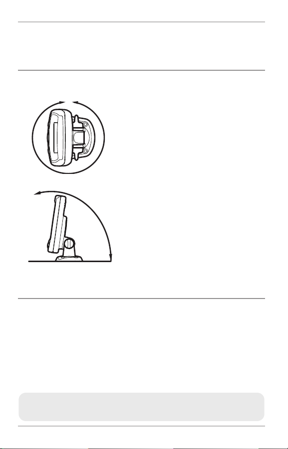
• Your PiranhaMAX™ may have one of two
different types of mounting bases, either a tilt
mounting base or a tilt and swivel mounting
base. The mounting area should allow
sufficient room for the unit to pivot freely, to
swivel if capable, and for easy removal and
installation (Figures 1 and 2).
The control head power cable can be connected to the electrical system of the
boat at two places: a fuse panel usually located near the console, or directly
to the battery.
NOTE: Make sure that the power cable is not connected to the control head at the
beginning of this procedure.
2
Page 9
GROUNDGROUND
POSITIVEPOSITIVE
Control Head Installation
NOTE: Humminbird® is not responsible for over-voltage or over-current failures. The
control head must have adequate protection through the proper selection and
installation of a 1 amp fuse.
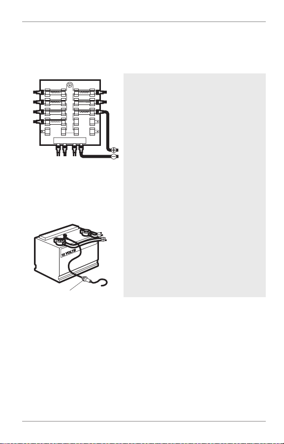
1a. If a fuse terminal is available, use
crimp-on type electrical connectors
(not included) that match the terminal
on the fuse panel. Attach the black
wire to ground (-), and the red wire to
positive (+) 12 VDC power (Figure 3).
Install a 1 amp fuse (not included) for
protection of the unit. Humminbird® is
Figure 3
not responsible for over-voltage of
over-current failures.
or...
1b. If you need to wire the control head
directly to a battery, obtain and install
an inline fuse holder and a 1 amp
fuse (not included) for the protection
of the unit (Figure 4). Humminbird® is
not responsible for over-voltage or
Inline Fuse Holder
Figure 4
over-current failures.
NOTE: In orderto minimize the potential for interferencewith other marine electronics,
a separate power source (such as a second battery) may be necessary.
3
Page 10
Control Head Installation
Assembling the Control Head Base
Your control head base will either have a tilt mount or a tilt and swivel mount.
Refer to procedures A or B below to assemble and mount the control head
base.
A. If you have a tilt mount, follow these steps:
1. Set the tilt mount control head base in place on the mounting surface.
Mark the four mounting screw locations with a pencil or punch.
2. Set the base aside, and drill the four mounting screw holes using a
9/64" bit.
3. Proceed to Routing the Control Head Cables Under the Deck.
Tilt and Swivel Mount
Control Head Base Assembly
Mount Arms
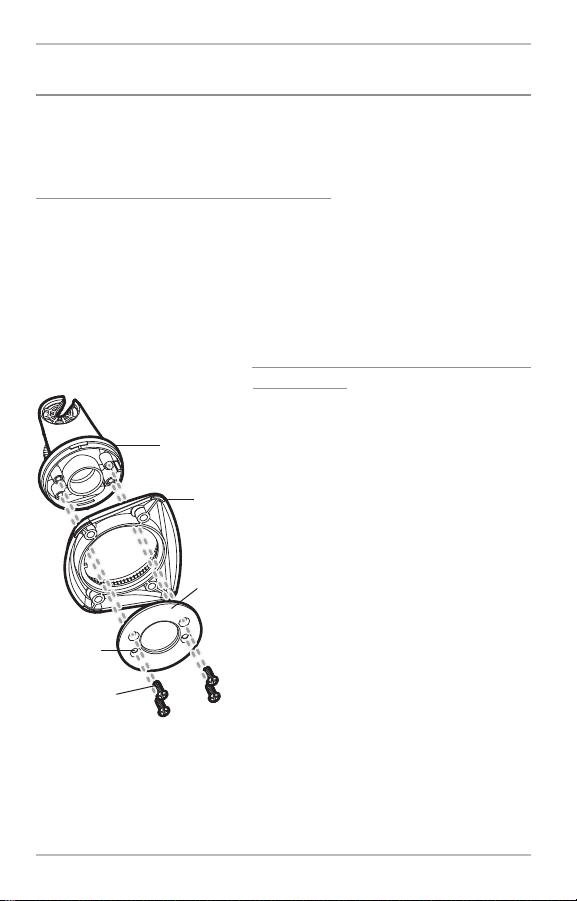
B. If you have a tilt and swivel mount, follow
these steps:
1. Insert the mount arms into the base.
Then, hold the mount arms in place as
you turn the base upside down.
2. Insert the swivel ring into the base, with
Base
the countersink holes for the arm screws
facing out.
3. Secure the mount arms with the 4 #6
Swivel
Ring
screws provided (Figure 5). Hand tighten
only!
Countersink
Side Out
Arm Screws,
4 #6 x7/16"
Figure 5
4. Set the assembled control head base in
place on the mounting surface. Mark the
four mounting screw locations with a
pencil or punch.
5. Set the base aside, and drill the four
mounting screw holes using a 9/64" bit.
6. Proceed to Routing the Control Head
Cables Under the Deck.
4
Page 11
3
/
4
”
1
9
m
m
Control Head Installation
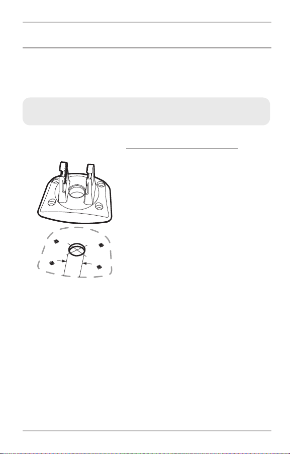
Routing the Control Head Cables Under the Deck
Use the following steps to route the control head cables under the deck.
NOTE: Under the deck cable routing is not always possible. If this is not an option,
the cables should be routed and secured above deck.
NOTE: See the installation section for your transducer type in order to plan the
location of the transducer and cable route.
Tilt Mount or Tilt and Swivel Mount
Control Head Base
Figure 6
Tilt Mount or Tilt and Swivel Mount:
1a. Mark and drill a 3/4" hole as shown in
Figure 6. Route the cables through the
hole. The cables will exit through the
center hole on the control head base.
1b. If the cables cannot be routed directly
beneath the control head base, mark
and drill a 3/4" hole that will allow you
to run the cables close to the control
head base.
5
Page 12
Control Head Installation
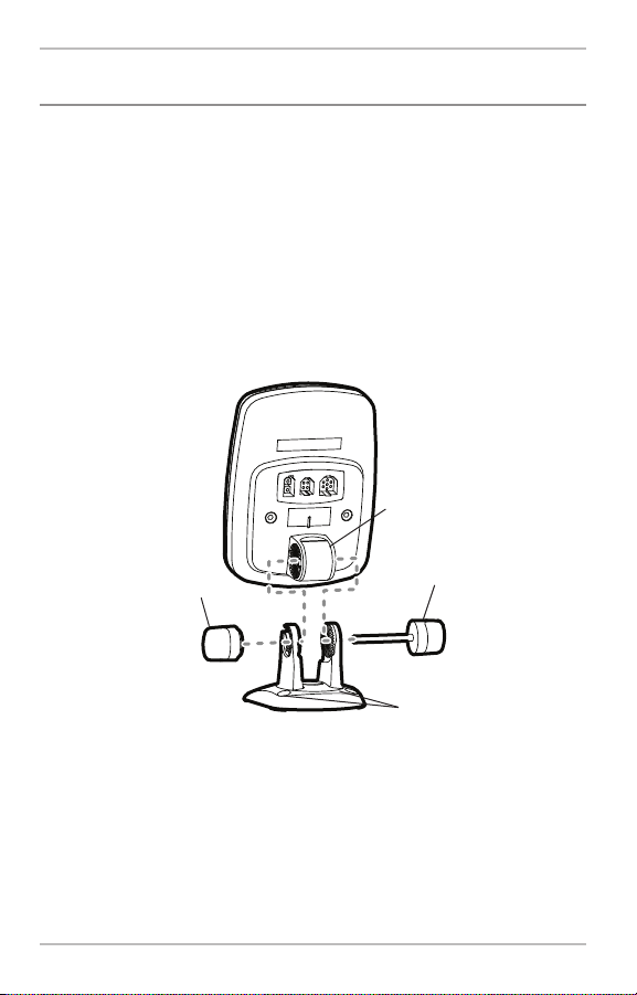
Attaching the Control Head to the Base
Follow these steps to attach the control head to the already-assembled base:
NOTE: The transducer cable and power cable should be routed prior to securing the
mounting bracket to the deck.
1. Apply marine-grade silicone sealant to the drilled holes for the
mounting bracket.
2. Place the mounting bracket on the mounting surface, aligning with the
drilled holes.
3. Insert the four #8 Phillips countersink wood screws into the mounting
holes and hand tighten only!
Pivot Knuckle
Gimbal Knob
Figure 7
Thumbknob Bolt
Mounting Holes
4. Insert the thumbknob bolt through the pivot knuckle on the control head
(Figure 7).
5. Align the pivot knuckle with the mount base arms and slide into place,
twisting slightly if necessary, until the unit is firmly seated.
6. Rotate the control head to the desired angle and hand tighten the
thumbknob bolt.
7. Thread the gimbal knob onto the pivot bolt and tighten.
6
Page 13

Control Head Installation
Attaching the Cables to the Control Head
Follow thesestepsto attach the power and transducer cablesto the control head:
1. Matching the cable plugs to the shape
and orientation of the sockets, insert the
transducer and power cables into the
correct sockets on the control head
(Figure 8).
Power Temperature Transducer
Figure 8
You are now ready to install the transducer. See Transducer Installation
Overview and then find the section that refers to your transducer type.
2. With the control head in place, tilt
and/or swivel the unit through its full
range to make sure there is enough
cable slack for the unit to move freely.
Hand tighten the thumbknob bolt when
you achieve the desired position for the
control head.
7
Page 14

Transducer Installation Overview
Transducer Installation Overview
The transducer can be installed on the transom of the boat, inside the hull, or
onto a trolling motor, depending on your transducer type. The type of
transducer you have will also determine how the cable will be routed. Go to
the section that describes your transducer, and follow the steps to position
and mount the transducer on your boat.
NOTE: Due to the wide variety of hulls, only general instructions are presented
in this installation guide. Each boat hull represents a unique set of requirements
that should be evaluated prior to installation. It is important to read the
instructions completely and understand the mounting guidelines before
beginning installation.
NOTE: If the included transducer will not work for your application, you may
exchange it, NEW and UNASSEMBLED, with mounting hardware included, for a
transducer appropriate for your application - often at very little or no charge
depending on the transducer. Call the Humminbird® Customer Resource Center at
1-800-633-1468 for details and pricing, or visit www.humminbird.com.
NOTE: In addition to the hardware supplied with your transducer, you will need a
powered hand drill and various drill bits, various hand tools, including a ruler or
straightedge,a level, a 12" plumb line (weighted string or monofilament line), marker
or pencil, safety glasses and dust mask, and marine-grade silicone sealant.
NOTE: Whendrilling holesin fiberglass hulls,it is best to start with a smallerbit and use
progressively largerdrill bitsto reducethe chance of chipping or flaking the outer coating.
8
Page 15
Transom Transducer Installation
Transom Transducer Installation
Locating the Transducer Mounting Position
Turbulence: You must first determine the best location on the transom to
install the transducer. It is very important to locate the transducer in an area
that is relatively free of turbulent water.Consider the following to find the best
location with the least amount of turbulence:
Areas of Possible Turbulence
Rivets Strakes
Transom Hull
Figure 9
Stepped Hull
Step
Figure 10
• As the boat moves through the water,
turbulence is generated by the weight of
the boat and the thrust of the propeller(s)
- either clockwise or counter-clockwise. This
turbulent water is normally confined to
areas immediately aft of ribs, strakes or
rows of rivets on the bottom of the
boat, and in the immediate area of the
propeller(s). Clockwise propellers create
more turbulence on the port side. On
outboard or inboard/outboard boats, it is
best to locate the transducer at least 15" to
the side of the propeller(s) (Figure 11).
•
The best way to locate turbulence-free
water is to view the transom while the boat
is moving. This method is recommended if
maximum high-speed operation is a high
priority. If this is not possible, select a
location on the transom where the hull
forward of this location is smooth, flat and
free of protrusions or ribs (Figure 9).
• On boats with stepped hulls, it may be
possible to mount the transducer on the
Rib
step. Do not mount the transducer on the
transom behind a step to avoid popping the
transducer out of the water at higher
speeds; the transducer must remain in the
water for the control head to maintain the
sonar signal (Figure 10).
9
Page 16
15”
Transom Transducer Installation
• If the transom is behind the propeller(s), it may be impossible to find an
area clear from turbulence, and a different mounting technique or
transducer type should be considered, such as an Inside the Hull
Transducer.
• If you plan to trailer your boat, do not mount the transducer too close to
trailer bunks or rollers to avoid moving or damaging the transducer
during loading and unloading of the boat.
• If high speed operation is critical, you may want to consider using an
In-Hull transducer instead of this Transom Mount transducer.
Level
Deadrise Angle
Find a turbulence-free location at least 15” from the propeller(s)
and not in line with trailer bunks or rollers. (Figure 11).
NOTE: The hydrodynamic shape of your transducer allows it to point straight down
without deadrise adjustment(Figure12).
Figure 12
NOTE: If you cannot find a transom mount location that will workfor your high-speed
application,find an In-Hull Transducer by contacting our Customer Resource Center at
either 1-800-633-1468or by visiting our website at www.humminbird.com.
10
Page 17

Preparing the Mounting Location
Positioning the MountingBracket
Level
Boat Hull Types Require
Different Mounting Positions
1/8” for aluminum
1/4” for fiberglass
Figure 14
Using the Mounting Bracket to
Mark the Initial Drill Holes
After determining the mounting location for the
transducer, follow the steps below to position and
mount the transducer bracket.
1. Make sure that the boat is level on the trailer,
Level
both from port to starboard and from bow to
stern, by placing your level on the deck of the
boat, first in one direction, then in the other.
2. Hold the mounting bracket against the transom
Figure 13
of the boat in the location you have selected
(Figure 13). Align the bracket horizontally, using
the level; make sure that the lower screw hole
protrusion does not protrude past the bottom of
the hull, and there is at least 1/4" clearance
between the bottom of the bracket and the
bottom of the transom for fiberglass boats, and
1/8" clearance for aluminum boats (Figure 14).
NOTE: If you have a flat-bottomed aluminumboat, some
additional adjustment may be needed to accommodate
therivets on the bottomof the boat(i.e.the gapmayneed
to be a littlesmaller than 1/8"). This will help you to avoid
excessive turbulenceat high speeds.
NOTE: If your propeller moves clockwise (in forward, as
you're facing the stern of the boat from behind), mount
the transducer on the starboard side. If your propeller
movescounter-clockwise (in forward,as you'refacing the
stern of the boat from behind), mount the transducer on
the port side.
3. Continue to hold the bracket on the transom of
the boat, and use a pencil or marker to mark
where to drill the two mounting holes. Mark the
drill holes near the top of each slot, making sure
that your mark is centered in the slot (Figure 15).
Transom Transducer Installation
Mark Initial
Drill Holes
3rd hole
Figure 15
NOTE: The third hole should not be drilled until the
angle and heightof thetransduceris finalized, which
youwillnot do untila later procedure.
11
Page 18

12”
-2 -1 0 1 2 3 4 5 6 7 8 9 10 11 12 13 14 15 16 17 18 19 20 21 22 23 24
Transom Angle (°)
Bead Alignment
Number
142531425
25 26 27328 29 30
1
Measured Distance (x)
1.1cm
1/2“
0.0 cm
0“
2.5 cm1“4.3 cm
1 5/8“
5.9 cm
2 3/8“
7.6 cm3“9.3cm
3 5/8“
11.1cm
4 3/8“
12.9cm5“14.9cm
5 7/8“
16.9cm
6 5/8“
Transom Transducer Installation
4. Make sure that the drill bit is perpendicular to the actual surface of the
transom, NOTparallel to the ground, beforeyou drill. Using a 5/32”bit, drill
the two holes only to a depth of approximately 1”.
NOTE: On fiberglass hulls, it is best to use progressively larger drill bits to reduce the
chance of chipping or flakingthe outer coating.
Assembling the Transducer and Initial Mounting
In this procedure, you will assemble the transducer using the hardware provided,
thenmount it and make adjustments to its position without locking it in place.
NOTE: You will initially assemble the transducer and the mounting bracket by matching
the two ratchets to a numbered position on the transducer knuckle. Further adjustments
maybe necessary.
1a. If you already know your transom angle, refer to the chart below for the
initial position to use to set the ratchets (Figure 16). If your transom is
angled at 14 degrees (a common transom angle for many boats) use
position 1 for the ratchets. In either case, go to step 2.
Figure 16
or...
Transom Angle
in degrees (°)
Measured Distance (X)
Measuring the Transom Angle
1b. If you do not know your transom angle,
measure it using a plumb line (weighted
nylon string or monofilament line) exactly
12 inches long. Hold the top of the plumb
line against the top of the transom with
Plumb
line
your finger, and wait until the line hangs
straight down (Figure 17). Using a ruler,
measure the distance from the bottom of
the plumb line to the back of the
transom, then use the chart (Figure 16).
Figure 17
NOTE: It is important to take your measurement
Weight
in the location shown in Figure 17, from exactly 12
inches down from the top of the transom.
12
Page 19

Transom Transducer Installation
2. Place the two ratchets, one on either side of the transducer knuckle, so
that the beads on each ratchet line up with the desired position number
on the knuckle (Figure 18a). If you are setting the ratchets at position 1,
the beads on each ratchet will line up with the rib on the transducer
knuckle to form one continuous line on the assembly (Figure 18b).
NOTE: The ratchets are keyed; make sure that the square teeth on each ratchet face
the square teeth on the transducer knuckle, and the triangular teeth face outward.
Hold the ratchets on the transducer knuckle with one hand and fit the
mounting bracket over them until it snaps into place with the other hand. Refer
to the illustration (Figure 18d).
Transducer Knuckle Positions
Ratchets Placed in Position 2
Rib
Knuckle
Figure 18a
Bead
Ratchet
Figure 18c
Ratchets Placed in Position 1
Rib at
position 1
Fitting the Mounting Bracket Over the Ratchet
13
Beads
Ratchet
Figure 18b
Figure 18d
Page 20

Transom Transducer Installation
Inserting the Pivot Bolt
Figure 19
Mounting the Assembly
to the Transom
Figure 20
Figure 21
3. Put the pivot bolt through the assembly to
hold it in position and loosely install the nut,
but do NOT tighten the nut at this time
(Figure 19).
4. Align the mounting bracket transducer
assembly with the drilled holes in the
transom. With a 5/16" socket driver, mount
the assembly to the transom using the two
#10 - 1" long screws provided (Figure 20).
Hand tighten only!
NOTE: Make sure that the mounting screws are
snug,but do not fully tighten the mounting screwsat
thistime to allowthe transducer assembly to slide for
adjustment purposes.
5. Adjustthe initial angleof the transducerfrom
back to front by rotating the transducer until
the side seam on the transducer is almost
parallel with the bottom of the boat,one click
ata timein eitherdirection (Figure 21 and 22).
Adjusting the Initial Transducer Angle
One click too high
Correctly aligned
(transducer side
seam aligned
with boat bottom)
Trailing edge
Leading edge
Figure 22
One click too low
14
Page 21

Transom Transducer Installation
Adjusting the Transducer
Mounting Position
Seam aligned with boat hull
Figure 23
Leveling the Mounting
Assembly Horizontally
Level
Figure 24
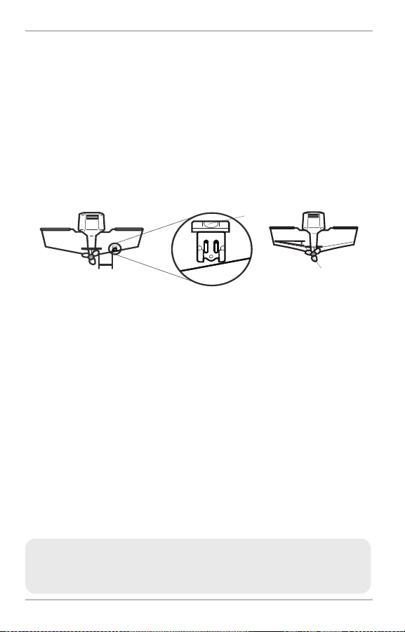
6. Adjust the transducer assembly vertically,
until the seam on the leading edge of the
transducer (the edge closest to the transom
of the boat) is level and just slightly below
the hull (Figure 23).
NOTE: The transducer has a natural downward slant
of 4-5 degrees fromleading edge (closest to the boat
transom) to trailing edge (farthest away from the
boat). Looking at the back of the transducer, the
seamshould be slightlybelow the bottom of thehull.
7. Continue to adjust until the bracket is also
level from port to starboard (horizontally
level as you look at the transducer from
behind the boat (Figure 24).
8. Mark the correctposition on the transom by
tracing the silhouette of the transducer
mounting bracket with a pencil or marker.
Level
9. Tighten the pivot bolt, usingthe pivotscrew
and nut to lock the assembly. Hand tighten
only!
10. Hand-tighten the two mounting screws.
NOTE: You will drill the third mounting hole and
finalize the installation after you route the cable and
test and finish the installation in the following
procedures.
15
Page 22

Transom Transducer Installation
Routing the Cable
The transducer cable has a low profile connector, which must be routed to the
point where the control head is mounted. There are several ways to route the
transducer cable to the area where the control head is installed. The most
common procedure routes the cable through the transom into the boat.
NOTE: Your boat may have a pre-existing wiring channel or conduit that you can
use for the transducer cable.
1. Unplug the other end of the transducer cable from the control head.
(The transducer cable was connected in the earlier section Attaching
the Cables to the Control Head). Make sure that the cable is long
enough to accommodate the planned route by running the cable over
the transom.
CAUTION! Do not cut or shorten the transducer cable, and try not to damage the
cable insulation. Route the cable as far as possible from any VHF radio antenna
cables or tachometer cables to reduce the possibility of interference. If the cable is
too short, extension cables are available to extend the transducer cable up to a total
of 50'.Forassistance,contactthe Customer Resource Centerat www.humminbird.com
or call 1-800-633-1468 for more information.
NOTE: Allow enough slack in the cable for slight movement at the pivot point. It is
best to route the cable to the side of the transducer so the transducer will not
damage the cable during movement.
2a. If you are routing the cable over the transom of the boat, secure the
cable by attaching the cable clamp to the transom, drilling 9/64"
diameter holes for #8 x 5/8" wood screws, then skip directly to step 5
to connect the cable.
or...
2b. If you will be routing the cable through a hole in the transom, drill a 5/8"
diameter hole above the waterline. Route the cable throughthis hole, then
fill the hole with marine-grade silicone sealant and proceed to the next
step immediately.
16
Page 23

Transom Transducer Installation
Figure 25
Storing Excess Cable
Figure 26
Routing the Cable
3. Place the escutcheon plate over the
cable hole and use it as a guide to
mark the two escutcheon plate
mounting holes. Remove the plate, drill
two 9/64" diameter x 5/8" deep holes,
and then fill both holes with
marine-grade silicone sealant. Place the
escutcheon plate over the cable hole and
attach with two #8 x 5/8" wood screws.
Hand tighten only!
4. Route and secure the cable by attaching
the cable clamp to the transom; drill one
9/64" diameter x 5/8" deep hole, then fill
hole with marine-grade silicone sealant,
then attach the cable clamp using a
#8 x 5/8" screw. Hand tighten only!
NOTE: If there is excess cable that needs to be
gathered at one location (as shown in the
illustration), dress the cable routed from both
directions so that a single loop is left extending
from the storagelocation. Doubling the cable up
from this point, form the cable into a coil.Storing
excess cable using this method can reduce
electronic interference (Figure 26).
5. Plug the cable connector back into the
control head. The slots are keyed to prevent
reverseinstallation, so be careful not to force
the connector into the holder.
Your control head is now ready for operation.
17
Page 24

Transom Transducer Installation
Test and Finish the Installation
Once you have installed both the control head and the transom transducer, and
have routed all the cables, you must perform a final test before locking the
transducer in place. Testing should be performed with the boat in the water.
1. Press POWER once to turn the control head on. If the unit does not
power up, make sure that the connector is fully plugged into the
terminal slot and that power is available.
2. If all connections are correct and power is available, the Humminbird®
control head will enter Normal operation.
3. If the bottom is visible on-screen with a digital depth readout, the unit
is working properly. Make sure that the boat is in water greater than 2'
but less than the depth capability of the unit, and that the transducer
is fully submerged, since the sonar signal cannot pass through air.
NOTE: The transducer must be submerged in water for reliable transducer detection.
4. If the unit is working properly, gradually increase the boat speed to test
high-speed performance. If the unit functions well at lowspeeds, but begins
to skip or miss the bottom at higher speeds, the transducer requires
adjustment.
5. If you have the correct angle set on the transducer, yet lose a bottom
reading at high speed, adjust the height and the running angle in small
increments to give you the ideal transducer position for your boat. First,
adjust the height in small increments (Figure 23).
NOTE: The deeper the transducer is in the water, the more likely that a rooster tail
of spray will be generatedat high speeds, so make sure that the transduceris as high
as it can be and still be submerged in the water.
If you are still not getting good high speed readings, you may need to
disassemble the transducer mounting assembly and re-position the ratchets
(Figures 18a - 18d).
If you do change the transducer position, re-trace the position of the
mounting bracket before proceeding.
18
Page 25

Transom Transducer Installation
NOTE: It is often necessary to make several incremental transducer adjustments
before optimum high speed performance is achieved. Due to the wide variety of boat
hulls, however, it is not always possible to obtain high speed depth readings.
6. Once you have reached a consistently good sonar signal at the desired
speeds, you are ready to lock down the transducer settings. Remove the
transducer from the bracket (after noting where the ratchets are
assembled),then re-align the mounting bracketagainst the transom of the
boat to match the traced silhouette. Check the bracket position with the
level again to make sure it is still level, then mark the third mounting hole
using a pencil or marker. Unscrew and remove the mounting screws and
the transducer bracket and set aside.
7. Drill the third mounting hole, using a 5/32” drill bit. Use a marine-grade
silicone sealant to fill all three drilled mounting holes, especially if the
holes penetrated the transom wall.
NOTE: On fiberglass hulls, it is best to use progressively larger drill bits to reduce the
chance of chipping or flaking the outer coating.
FullyTightenAll Three
Figure 27
Mounting Screws
8. Re-position the transducer bracket against
the transom of the boat, then hand-install
all three screws. Make sure that the
transducer location has not changed, then
fully tighten all three mounting screws
(Figure 27). Hand tighten only! Re-install
the transducer to the mounting bracket,
making sure to assemble the ratchets in the
same locationthey had before.(See Figures
18a - 18d and Figure 21 - 22). If you have
performed the preceding procedures
correctly, the transducer should be level
andat the rightheight for optimal operation.
19
Page 26

Inside the Hull Transducer Installation
Inside the Hull Transducer Installation
In-hull mounting generally produces good results in single thickness fiberglasshulled boats. Humminbird® cannot guarantee depth performance when
transmitting and receiving through the hull of the boat, since some signal loss
occurs. The amount of loss depends on hull construction and thickness, as well
as the installation position and process.
NOTE: In-hull mounting requires an installed and operational control head.
NOTE: The integral temperature probe will not work with in-hull mounting, so you
may either want to consider purchasing a Temp Sensor or obtaining a different
transducer. Humminbird® offers a transducer exchange program to swap the NEW
and UNASSEMBLED transducer, accompanied by mounting hardware, for one
without an integral temperature probe. Call the Humminbird® Customer Resource
Center at 1-800-633-1468 for details, or visit www.humminbird.com for more
information.
This installation requires slow-cure two-part epoxy. Do not use silicone or
any other soft adhesive to install the transducer, as this material reduces
the sensitivity of the unit. Do not use five-minute epoxy, as it has a
tendency to cure before all the air bubbles can be purged, thus reducing
signal strength.
20
Page 27

Inside the Hull Transducer Installation
Determine the Transducer Mounting Location
Decide where to install the transducer on the inside of the hull. Consider the
following to find the best location:
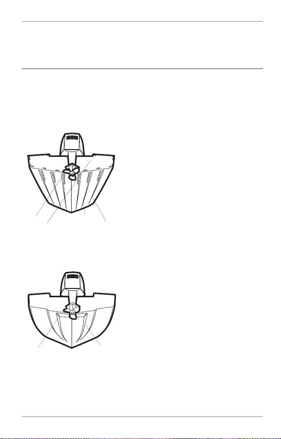
• Observe the outside of the boat hull to
find the areas that are mostly free from
turbulent water. Avoid ribs, strakes and
other protrusions, as these create
turbulence (Figure 28).
• As a general rule, the faster the boat
can travel, the further aft and closer to
the centerline of the hull the transducer
Figure 28
Preferred Mounting Area
has to be located in order to remain in
contact with the water at high speeds
(Figure 29).
Figure 29
21
Page 28

Inside the Hull Transducer Installation
Trial Installation
You will not be able to adjust the mounting after an inside the hull transducer
is installed. It is best, therefore, to perform a trial installation first that includes
running the boat at various speeds, in order to determine the best mounting
area before permanently mounting the transducer.
1. Plug the transducer into the control head, then power up the control
head. When the control head detects a functioning transducer, it will
automatically enter Normal operating mode.
2. View the sonar signal at its best by holding the transducer over the
side, immersed in the water, so that it is pointing straight down over a
known flat bottom. Use the display to benchmark against the sonar
signal that will be detected once the transducer is placed in the hull.
3. Place the transducer body face down at the identified mounting location
inside the hull, with the pointed end towards the bow (Figure 28).
4. Fill the hull with enough water to submerge the transducer body. Use
a sand-filled bag or other heavy object to hold the transducer in
position. The transducer cannot transmit through air, and the water
purges any air from between the transducer and the hull, and fills any
voids in the coarse fiberglass surface.
5. View the sonar signal on the display and compare against what was
observed in Step 2, making sure that the boat is in the same location
as it was during your observations in Step 2. If the results are
comparable, move on to Step 6. Otherwise, locate a new position in
the hull and repeat Steps 3 through 5.
6. Run the boat at various speeds and water depths while observing the
screen on the control head. If depth performance is required, test the
transducer in water at the desired depth. If the performance is
acceptable, move on to Step 7. If the performance is not acceptable,
repeat Steps 3 through 6.
7. Once you have determined the best mounting location using the above
steps, mark the position of the transducer.
22
Page 29

Inside the Hull Transducer Installation
Route the Cable
1. Once the mounting location is determined and you have marked the
position of the transducer, route the cable from the transducer to the
control head.
Permanently Mount the Transducer
1. Make sure the position of the transducer is marked.
2. You may have to disconnect the cable to the control head and
reconnect it at the end of this procedure.
3. Remove the water from inside the hull and thoroughly dry the
mounting surface. If the surface is excessively rough, it may be
necessary to sand the area to provide a smooth mounting surface.
4. Mix an ample quantity of two-part slow
cure epoxy slowly and thoroughly. Avoid
trapping air bubbles (Figure 30).
5. Coat the face of the transducer and the
inside of the hull with epoxy (Figures 28
and 30).
6. Press the transducer into place with a slight
twisting motion to purge any trapped air
from underneath, keeping the pointed end
of the transducer body pointed forward,
towards the bow (Figure 31).
Figure 30
Figure 31
NOTE: Neither water, spilled gasoline,nor oilwillaffectthe performance ofthetransducer.
NOTE: Proper operation requires the pointed end of
the transducer body to face towards the bow.
7. Weight the transducer so that it will not
move while the epoxy is curing.
NOTE: When the epoxy cures, no water is
necessary inside the hull.
8. If you unplugged the transducer cable at
the beginning of this procedure, plug it
back into the control head.
Your control head is now ready for operation.
23
Page 30

Trolling Motor Transducer Installation
Trolling Motor Transducer Installation
Several styles of the transducer are
compatible with trolling motor mounting.
(Figure 32). If you have a trolling motor
bracket, refer to the separate installation
instructions that are included with the
bracket.
Figure 32
You may purchase a Trolling Motor Adapter kit that will allow you to
mount the transducer on the trolling motor.
NOTE: Call the Humminbird® Customer Resource Center at 1-800-633-1468
for details and pricing, or visit www.humminbird.com for more information.
24
Page 31

Powering ON and OFF
Press and hold the POWER-MENU key until the PiranhaMAX™ powers on,
then release the key. To power off, press and hold the POWER-MENU key until
the unit shuts down.
When the PiranhaMAX™ powers on, the Start-Up menu
temporarily appears. From this menu, select either
Start-Up, Simulator, or SetUp.
• Use Start-Up for on the water use.
• Use Simulator for learning how to use the system with
simulated sonar data; access Simulator by pressing
the Right Arrow Key once.
• Use SetUp to display additional set-up menu choices;
access SetUp by pressing the Right Arrow Key twice
(See SetUp Menu for more information).
Display
LEFT Arrow Key
POWER/MENU Key
RIGHT Arrow Key
25
Page 32

What You See On the Display
The PiranhaMAX™ displays underwater information in an easy-to-understand
format. The top of the display corresponds to the water surface at the
transducer, and the bottom of the display corresponds to the Depth Range
automatically selected for the current water depth. The Bottom Contour varies
as the depth under the boat changes. Digital readouts provide precise
information for depth, fish and water temperature.
As the boat moves, terrain and bottom composition variations are displayed.
Fish, baitfish and thermoclines (underwater temperature changes) are
displayed when detected. Underwater conditions vary greatly, so some
experience and interpretation is needed to realize all the benefits of the
PiranhaMAX™ – use the following illustration as a guide to the most common
conditions and practice using your PiranhaMAX™ over known bottom types.
26
Page 33

PMAX150/190c (Single Beam) and
PMAX160/170 (Dual Beam) Display
2
3
7
9
10
* Units with 83 kHz Dual Beam sonar show targets in the widebeamas hollowfishicons.
1
4
5
6
8
1 - Water Surface Line
2 - Depth- Measuredat the Transducer
3 - Temperature
4 - Upper Range
5 - Surface Clutter
6 - Structure
7 - Bottom Contour
8 - Lower Range
9 - 83 kHz, Wide Beam Hollow FishSymbol (DualBeam Units only)*
10 - 200 kHz, Narrow Beam Shaded FishSymbol
11 - 455 kHz, Right Beam Fish Symbol(Tri Beam Unit only)**
12 - 455 kHz, Left Beam Fish Symbol(Tri Beam Unit only)**
PMAX180 (Tri Beam) Display
2
3
10
7
11
12
* Units with 455 kHz Tri Beam sonar show targetsin the left beamas left-looking fish
symbols, andtargetsin the right beam as right-looking fish symbols.
27
1
4
5
6
8
Page 34

PiranhaMAX™ Sonar Technology
The PiranhaMAX™ is the easiest to use fishfinder ever. For most anglers, all
you’ll ever need to do is power on and fish! The PiranhaMAX™ automatically
determines depth and makes adjustments to keep the bottom and fish visible
on the display.
The PiranhaMAX™ uses sonar technology to send sound waves from the
transducer into the water. The returned “echoes” are plotted on the display,
creating a very accurate picture of the underwater world, including distance
to underwater objects such as the bottom, fish, and structure.
Your PiranhaMAX™ will have Single, Dual, or Tri Beam sonar. Find the correct
sonar description that applies to your unit.
28
Page 35

Single Beam Sonar
The PiranhaMAX™150 and PiranhaMAX™190c use a 200 kHz single beam
sonar system with a 20° area of coverage. Boat speed, wave action, bottom
hardness, water conditions and transducer installation can all affect depth
capability.
Dual Beam Sonar
The PiranhaMAX™160 and PiranhaMAX™170 use a 200/83 kHz dual beam
sonar system with a wide (60°) area of coverage. Dual Beam sonar is optimized
to show the greatest bottom definition using a narrow (20°) beam yet can still
indicate fish found in the wide (60°) beam when the Fish ID+
on. Dual Beam is ideal for a wide range of conditions - from shallowto very deep
water in both fresh and salt water. Boat speed, wave action, bottom hardness,
water conditions and transducer installation can all affect depth capability.
TM
feature is turned
Tri Beam Sonar
The PiranhaMAX™180 uses two frequencies and three different sonar
elements, one narrow, two wide, that transmit signals to the left, right and
straight down from your boat. The downward beam is 200 kHz with a 20° area
of coverage. This beam maintains a continuous digital depth readout from the
bottom directly beneath your boat. The side beams are 455 kHz with a 35°
area of coverage, for a total 90° area of coverage. Boat speed, wave action,
bottom hardness, water conditions, and transducer installation can all affect
depth capability.
29
Page 36

The Menu System
A simple menu system allows you to access your PiranhaMAX™ adjustable
settings. To activate the menu system, press the POWER-MENU key.Press the
POWER-MENU key repeatedly to display the PiranhaMAX™ menu settings,
one at a time. When a menu setting is on the display, use the RIGHT and LEFT
Arrow keys to adjust the menu setting. Menus settings are saved and removed
from the screen automatically after several seconds. In Normal operating mode,
most menu settings savedto memorywill not return to their defaultvalues when
the unit is turned off. See individual menu choices for more information.
NOTE: Each time the POWER-MENU key is pressed, the backlight momentarily
illuminates for easy viewing at night. Adjust the LIGHT menu setting to keep the
backlight on.
NOTE: If Simulator Mode is selected from the Start-Up Menu and a transducer is
plugged in, some menu setting changes will be saved in memory even after the unit
is powered down. Menu setting changes will not be saved from Simulator mode
when a transducer is not connected.
NOTE: Turning on the SetUp menu choice from the Main Menu System allows you
to access additional set-up menu choices. See SetUp Menu for more information.
Light
(Setting Not Saved in Memory)
Press the POWER-MENU key until LIGHT appears. Use the backlight for night
fishing. Select either 0 (Off), or 1 through 5 to activate the backlight at the
desired level. (0 to 5, Default = 0 [PiranhaMAX™150/160/170/180]; 0 to 10,
Default = 10 [PiranhaMAX™190c])
NOTE: Continuous backlight operation will significantly decrease the battery life for
PiranhaMAX™ Portables.
Sensitivity
(Setting Saved in Memory)
Pressthe POWER-MENU key untilSENSITIVITY appears. Sensitivity controlshow
much detail is shown on the display. Increasing the sensitivity shows more sonar
returns from small baitfish and suspendeddebris in the water; however, the display may become too cluttered. When operating in very clear water or greater
depths, increased sensitivity shows weaker returns that may be of interest. Decreasing the sensitivity eliminates the clutter from the display that is sometimes
present in murky or muddy water. If Sensitivity is adjusted too low, the display
may not show many sonar returns that could be fish. (0 – 10, Default = 5)
30
Page 37

Depth Range
(Setting Not Saved in Memory)
Press the POWER-MENU key until DEPTH RANGE appears. Automatic is the
default setting. Whenin automatic, the lower range will be adjusted by the unit
to follow the bottom. (Auto, 15 to 600 ft [PiranhaMAX™150/160], 15 to 800 ft
[PiranhaMAX™170/180/190c], Default = Auto)
NOTE: In manual operation, if the depth is greater than the depth range setting,
the bottom will not be visible on the display. Select AUTO to return to automatic
operation.
Zoom
(Setting Not Saved in Memory)
Press the POWER-MENU key until ZOOM appears. Select Auto to magnify the
area around the bottom in order to reveal fish and structure close to the bottom
that may not be visible during normal operation. When ZOOM is set to Auto, the
upper and lower DepthRangesareautomaticallyadjusted to keep the areaabove
and below the bottom on the display. Select Off to return to normal operation.
(Off, Auto, Manual Ranges, Default = Off)
Upper
Zoom Range
Structure
Magnified Bottom
with More Detail
Lower
Zoom Range
There is also a series of manual ranges which can be selected. The manual
depth ranges are determined by the present depth conditions.
31
Page 38

Chart Speed
(Setting Saved in Memory)
Press the POWER-MENU key until CHART SPEED appears. Select a setting
from 1-5 to increase or decrease the chart speed, where 1 is the slowest and
5 is the fastest chart speed. Chart speed determines the speed at which the
sonar information moves across the display, and consequently the amount of
detail shown. A faster speed shows more information and is preferred by most
anglers; however, the sonar information moves across the display quickly. A
slower speed keeps the information on the display longer, but the bottom and
fish details become compressed and may be difficult to interpret. (1 to 5,
Default = 5)
Fish Alarm
(Setting Saved in Memory)
Press the POWER-MENU key until FISH ALARM appears. Select Off for no fish
alarm, or one of the following symbols to set the alarm. An alarm will sound
when the PiranhaMAX™ detects fish that correspond to the alarm setting.
Fish Alarm will only sound if Fish ID+™ is also set to On. (Off, Large,
Large/Medium, All, Default = Off)
Large fish only
Large/Medium fish only
All fish
Depth Alarm
(Setting Saved in Memory)
Press the POWER-MENU key until DEPTH ALARM appears. Select OFF for no
Depth Alarm, or select 3 to 99 feet to set the alarm depth. An audible alarm
sounds when the depth is equal to or less than the setting. (Off, 3 to 99 feet,
Default = Off)
32
Page 39

Filter
(Setting Saved in Memory)
Press the POWER-MENU key until FILTER appears. Select either Off or On.
Filter adjusts the sonar filter to limit interference on the display from
sources such as your boat engine, turbulence, or other sonar devices.
(On, Off, Default = Off)
SetUp Menu
(Setting Not Saved in Memory)
Press the POWER-MENU key until SetUp appears. Press the RIGHT Arrow key
to select On. (Off, On, Default = Off)
When you activate SetUp, additional menu choices will become available that
are not a part of the Main Menu system. After selecting SetUp, press the
POWER-MENU key to display the SetUp menu choices, one at a time. SetUp
Menu choices include:
• Contrast • Battery Alarm
• Fish ID+
• Bottom View • Units (International only).
Scroll through all SetUp menu choices to exit the SetUp menu.
TM
• Language (International only)
Contrast (SetUp Menu)
(Setting Saved in Memory, Monochrome only)
Make sure that the SetUp menu is selected, then press the POWER-MENU key
until CONTRASTappears. Select a setting from 1 through 5. (1 to 5, Default = 3)
Scroll through all SetUp menu choices to exit the SetUp menu.
33
Page 40

Fish ID+TM(SetUp Menu)
(Setting Saved in Memory)
Make sure that the SetUp menu is selected, then press the POWER-MENU key
until FISH ID+
view Fish symbols. Fish ID+
sonar returns, and will display a Fish Symbol when very selective requirements
are met. A select number of possible fish returns will be displayed with their
associated depth. (On, Off, Default = On)
Scroll through all SetUp menu choices to exit the SetUp menu.
T
M
appears. Select either Off to view “raw” sonar returns or On to
TM
uses advanced signal processing to interpret
Raw Sonar,
T
Fish ID+
Off
Single Beam
Raw Sonar,
TM
Fish ID+
Off
Dual Beam
Raw Sonar,
TM
Fish ID+
Off
Tri Beam
200 kHz
M
Narrow beam,
TM
On
Fish ID+
200 kHz
Narrow beam,
TM
Fish ID+
200 kHz
Narrow beam,
TM
Fish ID+
83 kHz
Wide beam,
TM
On
Fish ID+
On
455kHz
Leftand rightbeam,
TM
On
On
FishID+
NOTE: Returns from the 200 kHz narrow beam are shown with shaded fish
symbols while the 83 kHz wide beam (and 455 kHz beam) returns are displayed
with hollow fish symbols.
NOTE: Hollow fish symbols are not available on 200 kHz Single Beam sonar units.
Bottom View (SetUp Menu)
(Setting Saved in Memory)
Make sure that the SetUp menu is selected, then press the POWER-MENU
key until BOTTOM VIEW appears. Bottom View selects the method used to
represent the bottom and structure on the display. (Structure ID, Black,
WhiteLine, Inverse, Default = Inverse)
Scroll through all SetUp menu choices to exit the SetUp menu.
34
Page 41

Structure ID® represents weak returns as light pixels
and strong returns as dark pixels. This has the
benefit of ensuring that strong returns will be clearly
visible on the display.
Black (Bottom Black) displays all pixels below the
bottom contour as black, regardless of signal strength.
This has the benefit of providing a high contrast
between the bottom and other sonar returns on the
display.
NOTE: Bottom Black View is not available on color
models.
WhiteLine™ highlights the strongest sonar returns in
white resulting in a distinctive outline. This has the
benefit of clearly defining the bottom on the display.
Inverse is a method where weak returns are shown
with dark pixels and strong returns with lighter pixels.
This has the benefit of ensuring that weak signals will
be clearly visible on the display.
NOTE: Inverse View is not available on color models.
35
Page 42

Battery Alarm (SetUp Menu)
(Setting Saved in Memory)
Make sure that the SetUp menu is selected, then press the POWER-MENU
key until BATTERY ALARM appears. Select Off or 8.5 to 13.5 Volts. Battery
Alarm sounds when the input battery voltage is equal to or less than the menu
setting. (Off, 8.5 to 13.5 Volts, Default = Off)
Scroll through all SetUp menu choices to exit the SetUp menu.
Language (SetUp Menu)
(Setting Saved in Memory, International only)
Make sure that the SetUp menu is selected, then press the POWER-MENU
key until LANGUAGE appears (International Units only). LANGUAGE selects
the display language for menus. (Settings vary, Default = English)
Scroll through all SetUp menu choices to exit the SetUp menu.
Units (SetUp Menu)
(Setting Saved in Memory, International only)
Make sure that the SetUp menu is selected, then press the POWER-MENU
key until UNITS appears (International Units only). UNITS selects the units of
measure. (Feet/F, Meters/C, Fathoms/C, Default = Meters/C, where F stands
for Fahrenheit and C stands for Celsius)
Scroll through all SetUp menu choices to exit the SetUp menu.
36
Page 43

Maintenance
Your PiranhaMAX™ is designed to provide years of trouble-free operation with
virtually no maintenance. Follow these simple procedures to ensure your
PiranhaMAX™ continues to deliver top performance.
If the unit comes into contact with salt spray, wipe the affected surfaces with a
cloth dampened in fresh water.
Do not use a chemical glass cleaner on the lens - this may cause cracking in
the lens.
When cleaning the LCD protective lens, use a chamois and non-abrasive, mild
cleaner. Do not wipe while dirt or grease is on the lens. Be careful to avoid
scratching the lens.
If your boat remains in the water for long periods of time, marine growth can
reduce the effectiveness of the transducer. Periodically clean the face of the
transducer with liquid detergent.
If your boat remains out of the water for a long period of time, it may take some
time to wet the transducer when returned to the water. Small air bubbles can
cling to the surface of the transducer and interfere with proper operation. These
bubbles dissipate with time, or you can wipethe faceof the transducer with your
fingers after the transducer is in the water.
Never leave the unit in a closed car or trunk—the extremely high temperatures
generated in hot weather can damage the electronics.
37
Page 44

Troubleshooting
Do not attempt to repair the PiranhaMAX™ yourself. There are no
user-serviceable parts inside, and special tools and techniques are required
for assembly to ensure the waterproof integrity of the housing. Repairs should
be performed only by authorized Humminbird technicians.
Many requests for repair received by Humminbird® involve units that do not
actually need repair. These units are returned “no problem found.” If you have a
problem with yourPiranhaMAX™, use the followingtroubleshooting guide before
calling the Customer Resource Center or sendingyour unit in for repair.
1. Nothing happens when I turn the unit on.
Check the powercable connectionat bothends. Be sure the cable is connected
correctly to a reliable power source — red lead to positive, black lead to
negative or ground. Ensure the power available is between 10 and 20 VDC. If
the unit is wired through a fuse panel, ensure the panel is powered. Often
accessoryfusepanels arecontrolledbya separate switch or theignition switch.
Also,often a fuse can appear to be good when it is not. Check the fuse with a
tester or replace it with a fuse known to be good.
Check the power connection to the PiranhaMAX™. It is possible to force the
power cable connector into the cable holder incorrectly. If the connector is
reversed, the unit will not work. Examine the contacts on the back of the unit
to ensurethere is no corrosion.
2. There is no transducer detected.
The PiranhaMAX™ has the ability to detect and identify that a transducer
is connected. When powering on, if a message indicates “transducer not
connected”,make sure that an appropriate transducer connector is plugged
into the unit. In addition, inspect the transducer cable from end to end for
breaks, kinks, or cuts in the outer casing of the cable. Also make sure that
the transducer is fully submerged in water. If the transducer is connected
to the unit through a switch, temporarily connect it directly to the unit and
try again. If none of these actions identifies an obvious problem, the
transducer itself is probably at fault. Be sure to include the transducer if
returning the unit for repair.
38
Page 45

3. There is no bottom reading visible on the display.
If the loss of bottom information occurs only at high boat speeds, the
transducer needs adjusting – see your PiranhaMAX™ Installation Guide for
details. Also, in very deep water, it may be necessary to increase the
sensitivity setting manually to maintain a graphic depiction of the bottom. If
you are using a transducer switch to connect two transducers to the
PiranhaMAX™, make sure that the switch is in the correct position to connect
a transducer that is in the water. (If a trolling motor transducer is selected and
the trolling motor is out of the water, no sonar information appears.) If none of
theseactions solves the problem, inspect the transducer cablefromend to end
for breaks, kinks, or cuts in the outer casing of the cable. If the transducer is
connected to the unitthrough a switch, temporarily connectit directly to theunit
and try again. If none of these actions identifies an obvious problem, the
transducer itself may be at fault. Be sure to include the transducer if returning
the unit for repair.
4. When in very shallow water, I get gaps in the bottom reading and
inconsistent digital depth indication.
The PiranhaMAX™ will work reliably in water 3 feet (90 cm) or deeper.
Remember that the depth is measured from the transducer, not from the
surface of the water.
5. The unit comes on before I press the POWER-MENU key, and won’t
turn off.
Check the transducer cable — if the outer jacket of the cable has been cut
and the cableis in contactwithbare metal, you will need to repair the cut with
electricaltape.If thereis no problem with the cable, disconnect thetransducer
from the unit and see if the problemis corrected, to confirm the source of the
problem.
6. I get gaps in the reading at high speeds.
Your transducer needs adjusting. If the transducer is transom-mounted, there
are two adjustments available to you: height, and running angle. Make small
adjustments and run the boat at high speeds to determine the effect. It may
takeseveral tries to optimizehigh-speed operation. Thiscan also be a resultof
air or turbulence in the transducer location caused by rivets, ribs, etc.
39
Page 46

7. My unit loses power at high speeds.
Your PiranhaMAX™ has over-voltage protection that turns the unit off when
input voltage exceeds 20 VDC. Some outboard motors do not effectively
regulate the poweroutputof the engine’s alternator and can produce voltage
in excess of 20 Volts when running at high RPMs.
8. The display begins to fade out. Images are not as sharp as normal.
Checkthe input voltage. ThePiranhaMAX™ willnot operate on input voltages
below10 VDC.
9. The display shows many black dots at high speeds and high
sensitivity settings.
You are seeing noise or interference caused by one of several sources. Noise
can be caused by electronic devices. Turn off any nearby electronics and see
if the problem goes away. Noise can also be caused by the engine. If engine
noise is causing the interference, the problem will intensify at higher RPMs.
Increase the engine speed with the boat stationary to isolate this cause.
Propeller cavitation can also appear as noise on the display. If the transducer
is mounted too close to the propeller, the turbulence generated can interfere
with the sonar signal. Make sure that the transducer is mounted at least 15"
(380 mm) from the propeller.
40
Page 47

International Purchases
A separate warranty is providedby international distributors for units purchased
outsidethe United States. This warrantyis includedby your local distributor and
this distributor maintains local service for your unit. Warranties are only valid in
the area of intendeddistribution.Unitspurchased in the United States or Canada
must be returned to our factory in the United States for service.
41
Page 48

Humminbird® 1-Year Limited Warranty
We warrant the original retail purchaser that products made by Humminbird®
have been manufactured free from defects in materials and workmanship. This
warranty is effective for one year from the date of original retail purchase.
Humminbird® products found to be defective and covered by this warranty will
be replaced or repaired free of charge at Humminbird’s option and returned to
the customer freight prepaid. Humminbird’s sole responsibility under this
warranty is limited to the repair or replacement of a product that has been
deemed defectiveby Humminbird®. Humminbird®is not responsible for charges
connected with the removal of such product or reinstallation of replaced or
repaired parts.
This warranty does not apply to a product that has been:
• Improperly installed;
• Used in an installation other than that recommended in the product
installation and operation instructions;
• Damaged or has failed because of an accident or abnormal operation;
• Repaired or modified by entities other than Humminbird®.
Please retain your original receipt as a proof of the purchase date. This will be
required for in-warranty service.
THIS WARRANTY IS EXPRESSLY IN LIEU OF ANY OTHER WARRANTIES,
OBLIGATIONS OR LIABILITIES ON THE PART OF HUMMINBIRD® AND WILL
BE THE CUSTOMER'S EXCLUSIVE REMEDY, EXCEPT FOR ANY APPLICABLE
IMPLIED WARRANTIES UNDER STATE LAW WHICH ARE HEREBY LIMITED
IN DURATION TO ONE YEAR FROM THE DATE OF ORIGINAL PURCHASE.IN
NO EVENT WILL HUMMINBIRD® BE LIABLE FOR ANY INCIDENTAL OR
CONSEQUENTIAL DAMAGES FOR BREACH OF ANY EXPRESS OR IMPLIED
WARRANTY RELATING TO THE PRODUCTS.
Some states do not allow limitationson an implied warranty, or the exclusion of
incidental or consequential damages, so the above exclusions may not apply to
you. You may also have other rights, which vary from state to state.
42
Page 49

Humminbird® Service Policy
Even though you'll probably never need to take advantage of our incredible
service policy, it's good to know that we back our products this confidently.
We do it because you deserve the best. We will make every effort to repair
your unit within three business days from the receipt of your unit at our
factory. This does not include shipping time to and from our factory. Units
received on Friday are typically shipped by the following Wednesday, units
received Monday are typically shipped by Thursday, etc.
All repair work is performed by factory-trained technicians to meet exacting
factory specifications. Factory-serviced units go through the same rigorous
testing and quality control inspections as new production units.
After the original warranty period, a standard flat rate service charge will be
assessed for each repair (physical damage and missing parts are not included).
Any repairs made after the original warranty will be warranted for an
additional 90 days after service has been performed by our factory technicians.
You can contact our Customer ResourceCenter or visit our website to verify the
flat rate repair fee for your product (visit the Product Support section):
http://www.humminbird.com
We reserve the right to deem any product unserviceable when replacement
parts are no longer available or impossible to obtain. This Service Policy is valid
in the United States only. This applies only to Humminbird® products returned
to our factory in Eufaula, Alabama. This Service Policy is subject to change
without notice.
DOMESTIC (USA) CUSTOMERS:
PLEASE DO NOT RETURN THIS PRODUCT TO STORE FOR SERVICE
For all technical issues please call 1-800-633-1468
Or visit www.humminbird.com, click SUPPORT
Please reference product serial number and
model number when contacting Humminbird®.
43
Page 50

Returning Your Unit for Service
Before sending your unit in for repair, please contact the factory, either by phone
or by email, to obtain a Repair Authorization Number for your unit.
NOTE: Please do not return your Humminbird® to the store for service.
Please have your productmodel name and serial number availablebeforecalling
thefactory.If youcontact the factoryby e-mail,please include yourproduct model
name and serial number in the e-mail, and use Request for Repair Authorization
Number for your e-mail subject header. You should include your Repair
Authorization Number in all subsequent communications about your unit.
For IN-WARRANTY service, complete the following steps:
• Obtain a Repair Authorization Number from the Humminbird®
Customer Resource Center.
• Tag product with your name, street address, phone number and your
assigned Repair Authorization Number.
• Include a brief written description of the problem.
• Include a copy of your receipt (to show proof and date of purchase).
• Return product freight prepaid to Humminbird®, using an insured
carrier with delivery confirmation.
For OUT-OF-WARRANTY service, complete the following steps:
• Obtain a Repair Authorization Number from the Humminbird®
Customer Resource Center.
• Include payment in the form of credit card number and expiration date,
money order or personal check. Please do not send cash.
• Tag product with your name, street address, phone number and your
assigned Repair Authorization Number.
• Include a brief written description of the problem.
• Return product freight prepaid to Humminbird®, using an insured
carrier with delivery confirmation.
44
Page 51

Specifications
Depth Capability............................................................ 600 ft (185 m) – (PMAX150/160)
800 ft (250 m) – (PMAX170/180/190c)
Power Output .................................................................800 Watts (PTP) – (PMAX150/160)
1600 Watts (PTP) – (PMAX170/180/190c)
Operating Frequency............................................. 200 kHz Single Beam (PMAX150/190c)
200 kHz and 83 kHz Dual Beam™ (PMAX160/170)
200 kHz and 455 kHz Tri Beam (PMAX180 only)
Area of Coverage (PMAX150/190c) .......................................... 20° @ -10 dB in 200 kHz
Area of Coverage (PMAX160/170).............................................. 60° @ -10 dB in 83 kHz
20° @ -10 dB in 200 kHz
Area of Coverage (PMAX180).................................................... 20° @ -10 dB in 200 kHz
90°Total Coverage (Two 35° Beams)@ -10 dB in 455 kHz
Target Separation ............................................................................ 2 1/2 Inches (63.5 mm)
Power Requirement ............................................................................................. 10-20 VDC
LCD Matrix ..........................................................................160 V x 128 H – (PMAX150/160)
240 V x 160 H – (PMAX170/180)
320 V x 240 H – (PMAX190c)
Transducer...............................................................XNT-9-20-T – (PMAX150/160/170/190c)
XNT-9-QB-90-T – (PMAX180)
Transducer Cable Length ..................................................................................... 20 ft (6 m)
NOTE: Product specifications and features are subject to change without notice.
NOTE: Humminbird® verifies maximum stated depth in saltwater conditions,
however actual depth performance may vary due to transducer installation, water
type, thermal layers, bottom composition, and slope.
45
Page 52

Contact Humminbird®
Contact the Humminbird® Customer Resource Center
in any of the following ways:
By Telephone
(Monday - Friday 8:00 a.m. to 4:30 p.m. Central Standard Time):
1-800-633-1468
By e-mail
(typically we respond to your e-mail within three business days):
cservice@johnsonoutdoors.com
For direct shipping, our address is:
Humminbird
Service Department
678 Humminbird Lane
Eufaula, AL 36027 USA
46
 Loading...