

Humminbird PiranhaMAX 155 Installation And Operation Manual

PiranhaMAX 155
PiranhaMAX 155
Installation and Operations Manual
Installation and Operations Manual
532273-1_A

Thank You!
Thank you for choosing Humminbird®, the #1 name in marine electronics.
Humminbird has built its reputation by designing and manufacturing topquality, thoroughly reliable marine equipment. Your Humminbird is designed
for trouble-free use in even the harshest marine environment. In the unlikely
event that your Humminbird does require repairs, we offer an exclusiveService
Policy-free of charge during the first year after purchase, and available at a
reasonable rate after the one-year period. For complete details, see the
Warranty section of this manual. We encourage you to read this installation
and operations manual carefully in order to get full benefit fromall the features
and applications of your Humminbird product.
Contact Customer Service at 1-800-633-1468 or visit our Web site at
humminbird.com.
WARNING! This device should not be used as a navigational aid to prevent collision,
grounding, boatdamage,or personal injury. When the boat is moving, water depth may
change too quickly to allow time for you to react. Always operate the boat at very slow
speeds if you suspect shallow water or submerged objects.
WARNING! Disassembly and repair of this electronic unit should only be performed by
authorized service personnel. Any modification of the serialnumberor attempt to repair
the original equipment or accessories by unauthorizedindividuals willvoid the warranty.
WARNING! Do not travel at high speed with the unit cover installed. Remove the unit
cover before traveling at speeds above 20 mph.
WARNING! This product contains chemicals known to the State of California to cause
cancer and/or reproductive harm.
NOTE: Some features discussed in this manual require a separate purchase, and
some features are onlyavailable on international models. Everyeffort has beenmade
to clearly identify those features. Please read the manual carefully in order to
understand the full capabilities of your model.
NOTE: To purchase accessories for your fishfinder, visit our Web site at
humminbird.com or contact Customer Service at 1-800-633-1468.
NOTE: The procedures and features described in this manual are subject to change
without notice. This manual was written in English and may have been translated to
another language. Humminbird is not responsible for incorrect translations or
discrepancies between documents.
NOTE: The illustrations in this manual may not look the same as your product, but
your unit will function in the same way.
i

ATTENTION INTERNATIONAL CUSTOMERS: Products sold in the U.S. are not
intended for use in the international market. Humminbird international units
provide international features and are designed to meet country and regional
regulations. Languages, maps, time zones, units of measurement, and warranty
are examples of features that are customized for Humminbird international units
purchased through our authorized international distributors.
To obtain a list of authorized international distributors, please visit our Web site at
humminbird.com or contact Customer Service at (334) 687-6613.
Humminbird®, Fish ID+™, PiranhaMAX™, Structure ID™, and WhiteLine™ are trademarked
by or registered trademarks of Johnson Outdoors Marine Electronics, Inc.
Baekmuk Batang, Baekmuk Dotum, Baekmuk Gulim, and Baekmuk Headline are registered
trademarks owned by Kim Jeong-Hwan.
© 2014JohnsonOutdoors Marine Electronics, Inc. All rights reserved.
ii

Installation Overview 1
Fixed Control Head Installation 2
Determine Where to Mount........................................................................ 2
Connect the Power Cable to the Boat ........................................................ 2
Assemble the Control Head Base ................................................................ 4
Route the Control Head Cables Under the Deck ........................................ 4
Attach the Control Head to the Base.......................................................... 5
Attach the Cables to the Control Head ...................................................... 6
Transducer Installation Overview 6
Transom Transducer Installation 7
Determine the Transducer Mounting Position............................................ 7
Prepare the Mounting Location .................................................................. 9
Assemble the Transducer and Initial Mounting........................................ 10
Route the Cable ........................................................................................ 14
Test and Finish the Installation ................................................................ 16
Inside the Hull Transducer Installation 18
Determine the Transducer Mounting Location ........................................ 18
Trial Installation........................................................................................ 19
Route the Cable ........................................................................................ 20
Permanently Mount the Transducer ........................................................ 20
Trolling Motor Transducer Installation 22
PiranhaMAX Portable Case Assembly 23
Assemble the PiranhaMAX Mount .......................................................... 24
Assemble the Base and Handle................................................................ 24
Attach the Control Head to the Base and Handle .................................... 26
Route the Cables ...................................................................................... 27
Assemble the Portable Case .................................................................... 30
Charge and Install the Battery.................................................................. 31
Assemble the Transducer Mounting Bracket .......................................... 32
iii

Table of Contents
Stow the Portable Transducer
and Battery Charger into the Portable Case ............................................ 33
Installing the Portable Case on the Boat 34
Connect the Transducer and Power Cables to the Portable Case............ 34
Attach the Portable Case to the Boat ...................................................... 35
Mounting the Portable Transducer 36
Test the Transducer Prior to Installation .................................................. 36
Mount the Portable Transducer on the Boat ............................................ 36
Moving the Portable Fishfinder................................................................ 38
Power ON and OFF 39
PiranhaMAX Sonar Technology 40
Dual Beam Sonar...................................................................................... 41
What You See On the Display 42
The Menu System 43
Light (Setting Not Saved in Memory) ........................................................ 44
Sensitivity (Setting Saved in Memory) ...................................................... 44
Depth Range (Setting Not Saved in Memory) .......................................... 44
Zoom (Setting Not Saved in Memory)........................................................ 45
Chart Speed (Setting Saved in Memory) .................................................. 45
Fish Alarm (Setting Saved in Memory) ...................................................... 46
Depth Alarm (Setting Saved in Memory) .................................................. 46
Filter (Setting Saved in Memory) .............................................................. 46
Setup Menu (Setting Not Saved in Memory) ............................................ 47
Contrast (Setting Saved in Memory) .................................................... 47
Fish ID+ (Setting Saved in Memory) .................................................... 47
Bottom View (Setting Saved in Memory).............................................. 48
Battery Alarm (Setting Saved in Memory)............................................ 49
Language (Setting Saved in Memory, International Only).................... 49
Units (Setting Saved in Memory, International Only) ............................ 49
iv

Table of Contents
Maintenance 50
Troubleshooting 51
International Purchases 54
1-Year Limited Warranty 55
Humminbird Service Policy 56
Returning Your Unit for Service 57
Specifications 58
Contact Humminbird 60
NOTE: Entries in this Table of Contents which list (International Only) are only
available on products sold outside of the U.S. by our authorized International
Distributors. It is important to note that products sold in the U.S. are not intended
for resale in the international market. To obtain a list of authorized International
Distributors, please visit our Web site at humminbird.com or contact Customer
Service at 1-800-633-1468 to locate the distributor nearest you.
v

vi


Installation Overview
Before you start installation, we encourage you to read these instructions
carefully in order to get the full benefit from your PiranhaMAX.
There are three basic installation tasks that you must perform for the
PiranhaMAX:
• install the control head
• install the transducer
• test the complete installation and lock the transducer position.
If you purchased a PiranhaMAX Portable unit, proceed to PiranhaMAX
Portable Case Assembly for installation instructions. If you are planning a
fixed installation, proceed to Fixed Control Head Installation.
Supplies: In addition to the hardware supplied with your transducer, you will
need a powered hand drill and various drill bits, various hand tools, including
a ruler or straightedge, a level, a 12" plumb line (weighted string or
monofilament line), marker or pencil, safety glasses and dust mask, and
marine-grade silicone sealant.
1
Installation Overview
Fixed Control Head Installation
Determine Where to Mount
Begin the installation by determining where to mount the control head.
Consider the following to determine the best location:
• To check the location planned for the control
head, test run the cables for the power and
transducer. See the installation section for
your transducer type in order to plan the
location of the transducer.
• The mounting surface should be stable
Figure 1
Figure 2
Connect the Power Cable to the Boat
A 6' long power cable is included to supply power to the control head. You
may shortenor lengthen the cable using 18 gauge multi-stranded copper wire.
CAUTION! Some boats have 24 or 36 Volt electric systems, but the control head
MUST be connected to a 12 VDC power supply.
The control head power cable can be connected to the electrical system of the
boat at two places: a fuse panel usually located near the console, or directly
to the battery.
enough to protect the control head from
excessive wave shock and vibration, and
should provide visibility while in operation.
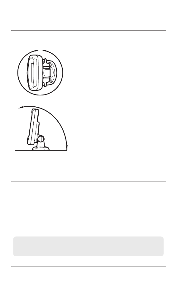
• Your PiranhaMAX uses a tilt mounting base.
The mounting area should allow sufficient
room for the unit to pivot freely, and for easy
removal and installation (Figures 1 and 2).
NOTE: Make sure that the power cable is not connected to the control head at
the beginning of this procedure.
Fixed Control Head Installation
2

NOTE: Humminbird is not responsible for over-voltage or over-current failures. The
GROUNDGROUND
POSITIVEPOSITIVE
control head must have adequate protection through the proper selection and
installation of a 1 amp fuse.
1a. If a fuse terminal is available, use
crimp-on type electrical connectors
(not included) that match the
terminal on the fuse panel. Attach the
black wire to ground (-), and the red
wire to positive (+) 12 VDC power
(Figure 3). Install a 1 amp fuse (not
included) for protection of the unit.
Humminbird is not responsible for
Figure 3
over-voltage or over-current failures.
or...
1b. If you need to wire the control head
directly to a battery, obtain and install
an inline fuse holder and a 1 amp
fuse (not included) for the protection
of the unit (Figure 4). Humminbird is
not responsible for over-voltage or
inline fuse holder
Figure 4
over-current failures.
NOTE: In order to minimize the potential for interference with other marine
electronics, a separate power source (such as a second battery) may be necessary.
3
Fixed Control Head Installation
Assemble the Control Head Base
3
/
4
”
1
9
m
m
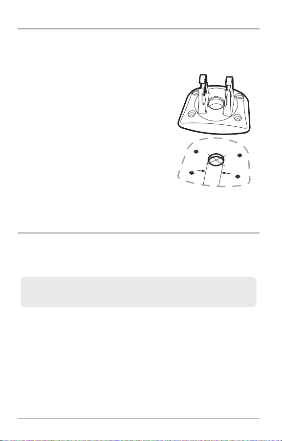
Your control head base will have a tilt mount. See the instructions below to
assemble and mount the control head base.
1. Set the tilt mount control head base in
Tilt Mount Control Head Base
place on the mounting surface.
2. Mark the four mounting screw
locations with a pencil or punch.
3. Set the base aside, and drill the four
mounting screw holes using a 9/64"
bit.
4. Proceed to Route the Control Head
Cables Under the Deck.
Figure 5
Route the Control Head Cables Under the Deck
Use the following steps to route the control head cables under the deck.
NOTE: Under the deck cable routing is not always possible. If this is not an option,
the cables should be routed and secured above deck.
NOTE: See the installation section for your transducer type in order to plan the
location of the transducer and cable route.
1a. Mark and drill a 3/4" hole as shown in Figure 5. Route the cables
through the hole. The cables will exit through the center hole on the
control head base.
1b. If the cables cannot be routed directly beneath the control head base,
mark and drill a 3/4" hole that will allow you to run the cables close to
the control head base.
Fixed Control Head Installation
4
Attach the Control Head to the Base
Follow these steps to attach the control head to the assembled base:
NOTE: The transducer cable and power cable should be routed prior to securing
the mounting bracket to the deck.
1. Apply marine-grade silicone sealant to the drilled holes for the
mounting bracket.
2. Place the mounting bracket on the mounting surface, aligning with the
drilled holes.
3. Insert the four #8 Phillips countersink wood screws into the mounting
holes. Hand tighten only!
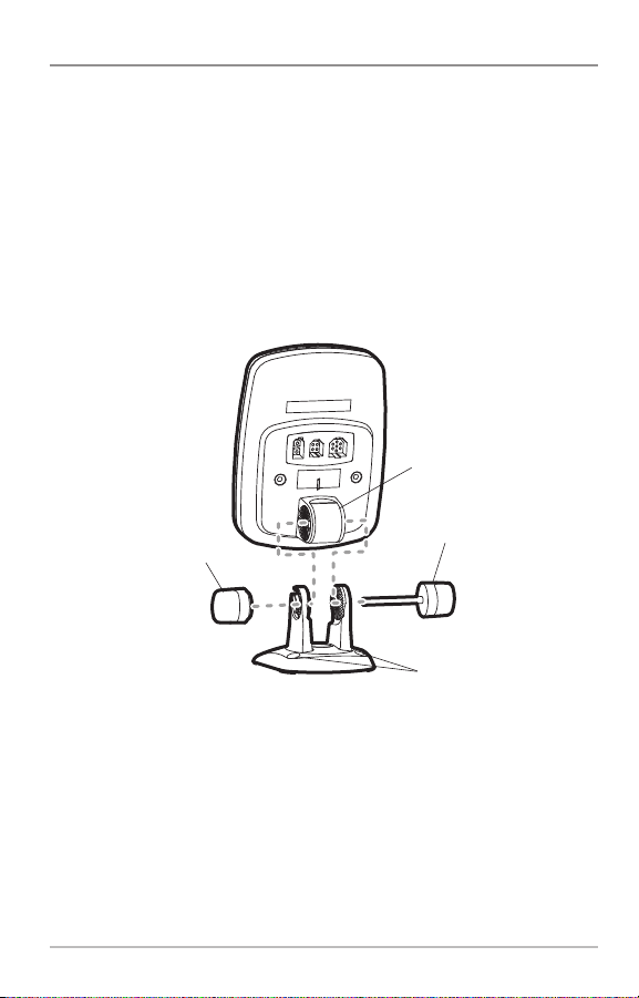
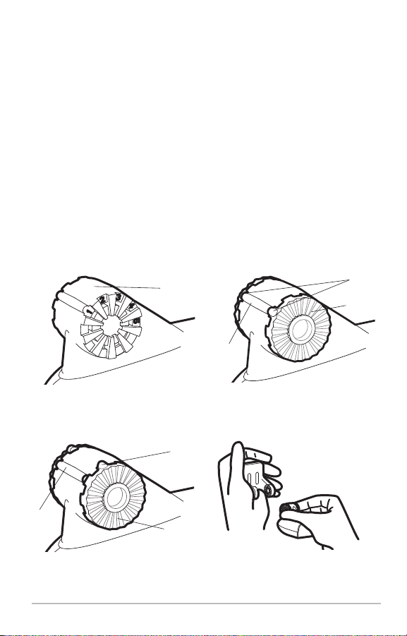
pivot knuckle
gimbal knob
thumbknob bolt
Figure 6
mounting holes
4. Insert the thumbknob bolt through the pivot knuckle on the control head
(Figure 6).
5. Align the pivot knuckle with the mount base arms and slide into place,
twisting slightly if necessary, until the unit is firmly seated.
6. Rotate the control head to the desired angle and hand tighten the
thumbknob bolt.
7. Thread the gimbal knob onto the pivot bolt and tighten.
5
Fixed Control Head Installation

Attach the Cables to the Control Head
Follow these steps to attachthe power and transducercables to the control head:
1. Matching the cable plugs to the shape
and orientation of the sockets, insert
the transducer and power cables into
the correct sockets on the control
head.
NOTE: Theserial portis for authorizedservice
personnel use only. Do not connecta cable to
this port. The serial port does not require a
port cover.
power serial transducer
Figure 7
2. With the control head in place, tilt the unit through its full range to
make sure there is enough cable slack for the unit to move freely. Hand
tighten the thumbknob bolt when you achieve the desired position for
the control head.
You are nowready to install the transducer. Proceed to Transducer Installation
Overview.
Transducer Installation Overview
The transducer can be installed on the transom of the boat, inside the hull, or
onto a trolling motor, depending on your transducer type. The type of
transducer you have will also determine how the cable will be routed. Go to
the section that describes your transducer, and follow the steps to position
and mount the transducer on your boat.
Due to the wide variety of hulls, only general instructions are presented in
NOTE:
this installation guide. Each boat hull represents a unique set of requirements that
should be evaluated prior to installation. It is important to read the instructions
completely and understand the mounting guidelines before beginning installation.
NOTE: When drilling holes in fiberglass hulls, it is best to start with a smaller bit and
use progressively larger drill bits to reduce the chance of chipping or flaking the
outer coating.
Transducer Installation Overview
6

Transom Transducer Installation
Following are instructions for transom mount installation. The transom mount
installation provides the least loss of signal since the transducer is mounted
outside the hull. This installation also allows adjustment of both running angle
and depth after the transducer is mounted, which enables you to tune the
installation for best results.
NOTE: If you cannotfind a transom mount location that will work for your boat hull,
a different mounting technique or transducer type should be considered. See the
FAQ (Frequently Asked Questions) section of our Web site at humminbird.com or
call Customer Service at 1-800-633-1468.
Determine the Transducer Mounting Position
Turbulence: You must first determine the best locationon the transom to install
the transducer. It is very important to locate the transducer in an area that is
relatively free of turbulent water. Consider the following to find the best
location with the least amount of turbulence:
Areas of Possible Turbulence
rivets strakes
transom hull
Figure 8
Stepped Hull
step
Figure 9
• As theboat movesthrough the water, turbulence
is generated by the weight of the boat and the
thrust of the propeller(s) - either clockwise or
counter-clockwise. This turbulent water is
normally confined to areas immediately aft of
ribs, strakes or rows of rivets on the bottom of
the boat, and in the immediate area of the
propeller(s). Clockwise propellers create more
turbulence on the port side. On outboard or
inboard/outboard boats, it is best to locate the
transducer at least 15" to the side of the
propeller(s) (Figure 10).
The best way to locate turbulence-free water is
•
to view the transom while the boat is moving.This
methodis recommended if maximumhigh-speed
operation is a high priority. If this is not possible,
select a location on the transom where the hull
forward of this locationis smooth, flat and free of
protrusions or ribs (Figure 8).
rib
7
Transom Transducer Installation
• On boats with stepped hulls, it may be possible to mount the transducer
15”
on the step. Do not mount the transducer on the transom behind a step to
avoid popping the transducer out of the water at higher speeds. Thetransducer must remain in the water for the control head to maintain the sonar
signal (Figure 9).
• If the transom is behind the propeller(s), it may be impossible to find an
area clear from turbulence, and a different mounting technique or
transducer type should be considered, such as an Inside the Hull
Transducer.
• If you plan to trailer your boat, do not mount the transducer too close to
trailer bunks or rollers to avoid moving or damaging the transducer during
loading and unloading of the boat.
• If high-speed operation is critical, you may want to consider using an
In-Hull Transducer instead of this Transom Mount Transducer.
level
deadrise angle
Figure 10
Find a turbulence-free location at least 15” from the propeller(s)
and not in line with trailer bunks or rollers. (Figure 10).
NOTE: The hydrodynamic shape of your transducer allows it to point straight down
without deadrise adjustment (Figure 11).
Figure 11
NOTE: If you cannot find a transom mount location that will work for your
high-speed application, visit the FAQ (Frequently Asked Questions) section of our
Web site at humminbird.com or call Customer Service at 1-800-633-1468.
Transom Transducer Installation
8

Prepare the Mounting Location
After determining the mounting location for the transducer, follow the steps
below to position and mount the transducer bracket.
Positioning the Mounting Bracket
level
Figure 12
Boat Hull Types Require
Different Mounting Positions
1/8” for aluminum
1/4” for fiberglass
Figure 13
Using the Mounting Bracket
to Mark the Initial Drill Holes
mark initial drill
holes
3rd hole
Figure 14
1. Make sure that the boat is level on the trailer,
both from port to starboard and from bow to
stern, by placing your level on the deck of the
boat, first in one direction, then in the other.
level
2. Holdthe mountingbracket against the transom
of the boat in the location you have selected
(Figure 12).Align the bracket horizontally, using
the level. Make sure that the lower screw hole
protrusion does not protrude past thebottom of
the hull, and there is at least 1/4" clearance
between the bottom of the bracket and the
bottom of the transom for fiberglass boats, and
1/8" clearance for aluminum boats (Figure 13).
NOTE: If you have a flat-bottomed aluminum boat,
some additional adjustment may be needed to
accommodate the rivets on the bottom of the boat
(i.e. the gap may need to be a little smaller than
1/8"). This will help you to avoid excessive
turbulence at high speeds.
NOTE: If your propeller moves clockwise as the
boat moves forward (as you're facing the stern of
the boat from behind), mount the transducer
on the starboard side, and align the bottom
right corner of the mounting bracket with the
bottom of the boat. If your propeller moves
counterclockwise as the boat moves forward (as
you're facing the stern of the boat from behind),
mount the transducer on the port side, and align
the bottomleft corner of themounting bracket with
the bottom of the boat.
3. Continue to hold the bracket on the transom of
the boat, and use a pencil or marker to mark
where to drill the two mounting holes. Mark
the drill holes near the top of eachslot, making
sure that your mark is centered in the slot
(Figure 14).
9
Transom Transducer Installation

12”
-2 -1 0 1 2 3 4 5 6 7 8 9 10 11 12 13 14 15 16 17 18 19 20 21 22 23 24
Transom Angle (°)
Bead Alignment
Number
142531425
25 26 27328 29 30
1
Measured Distance (x)
1.1cm
1/2“
0.0 cm
0“
2.5 cm1“4.3 cm
1 5/8“
5.9 cm
2 3/8“
7.6 cm3“9.3cm
3 5/8“
11.1cm
4 3/8“
12.9cm5“14.9cm
5 7/8“
16.9cm
6 5/8“
NOTE: The third hole should not be drilled until the angle and height of the
transducer is finalized, which you will not do until a later procedure.
4. Make sure that the drill bit is perpendicular to the actual surface of the
transom, NOT parallel to the ground, before you drill. Usinga 5/32” bit, drill
the two holes only to a depth of approximately 1”.
NOTE: On fiberglass hulls, it is best to use progressively larger drill bits to reduce
the chance of chipping or flaking the outer coating.
Assemble the Transducer and Initial Mounting
In this procedure, you will assemble the transducer using the hardwareprovided,
thenmount it and make adjustments to its position without locking it in place.
NOTE: You will initiallyassemble the transducer and the mounting bracket by matching
thetworatchetsto a numberedpositionon the transducer knuckle. Further adjustments
may be necessary.
1a. If you already know your transom angle, refer to the chart below for the
initial position to use to set the ratchets (Figure 15). If your transom is
angled at 14 degrees (a common transom angle for many boats) use
position 1 for the ratchets. In either case, go to step 2.
or...
1b. If you do not know your transom angle,
measure it using a plumb line (weighted
nylon string or monofilament line)
exactly 12 inches long. Hold the top of
the plumb line against the top of the
transom with your finger, and wait until
the line hangs straight down (Figure
16). Using a ruler, measure the distance
from the bottom of the plumb line to
the back of the transom, then use the
chart (Figure 15).
Transom Transducer Installation
10
Measuring the Transom Angle
plumb
line
transom
angle in
degrees
(°)
measureddistance(X)
Figure 15
weight
Figure 16
NOTE: It is important to take your measurement in the location shown in
Figure 16, from exactly 12 inches down from the top of the transom.
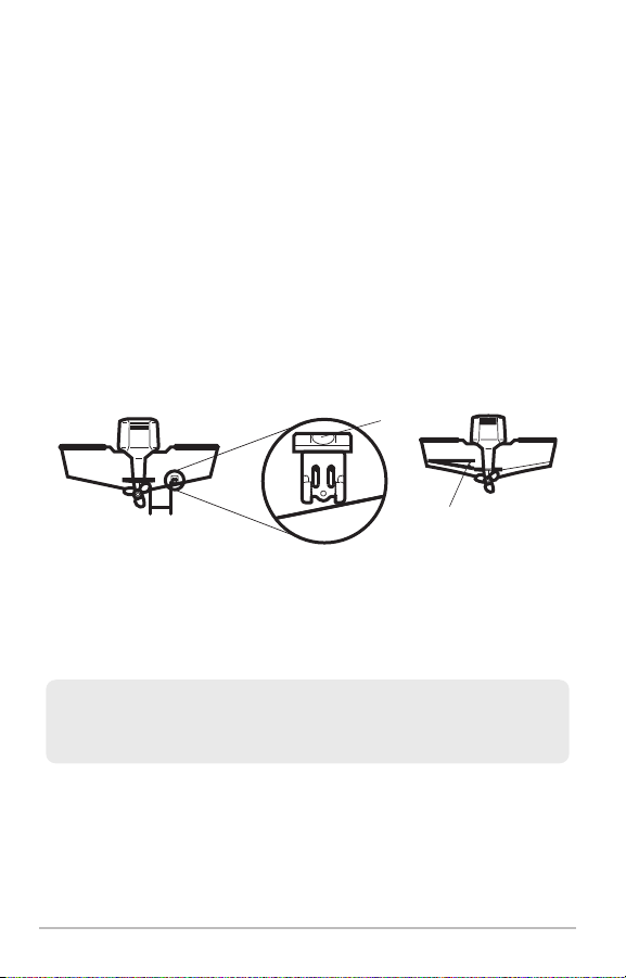
2. Place the two ratchets, one on either side of the transducer knuckle, so
that the beads on each ratchet line up with the desired position number
on the knuckle (Figure 17a). If you are setting the ratchets at position 1,
the beads on each ratchet will line up with the rib on the transducer
knuckle to form one continuous line on the assembly (Figure 17b).
NOTE: The ratchets are keyed. Make sure that the square teeth on each
ratchet face the square teeth on the transducer knuckle, and the triangular
teeth face outward.
Hold the ratchets on the transducer knuckle with one hand and fit the
mounting bracket overthem until it snaps into place with the other hand. Refer
to the illustration (Figure 17d).
Transducer Knuckle Positions
Ratchets Placed in Position 2
rib
knuckle
Figure 17a
bead
ratchet
Figure 17c
Ratchets Placed in Position 1
rib at
position 1
Fitting the MountingBracket Over the Ratchet
11
Transom Transducer Installation
beads
ratchet
Figure 17b
Figure 17d
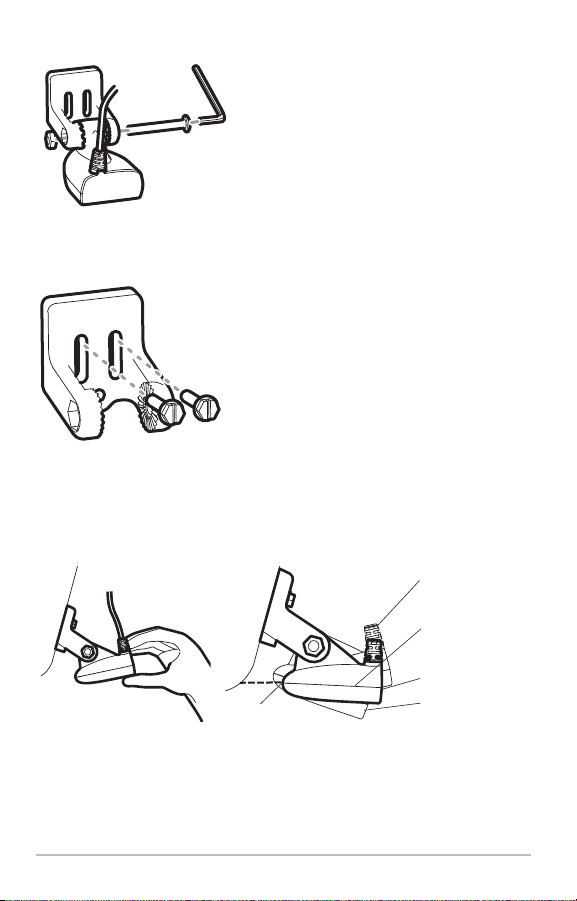
Inserting the Pivot Bolt
Figure 18
Mounting the Assembly
to the Transom
Figure 19
Figure 20
3. Put the pivot bolt through the assembly to
hold it in position and loosely install the nut,
but do NOT tighten the nut at this time
(Figure 18).
CAUTION! Do not use a high speed driver on this
combination of fasteners. Hand tighten only.
4. Align the mounting bracket transducer
assembly with the drilled holes in the
transom. With a 5/16" socket driver, mount
the assembly to the transom using the two
#10 - 1" long screws provided (Figure 19).
Hand tighten only!
NOTE: Make sure that the mounting screws are
snug,but do not fully tighten the mountingscrews
at this time to allow the transducer assembly to
slide for adjustment purposes.
5. Adjust theinitial angle of the transducer from
back to front by rotating the transducer until
the side seam on the transducer is almost
parallel with thebottom of the boat, one click
at a timein eitherdirection(Figure 20 and21).
Adjusting the Initial Transducer Angle
leading edge
Figure 21
one click too high
correctly aligned
(transducer side
seam aligned
with boat bottom)
trailing edge
one click too low
Transom Transducer Installation
12
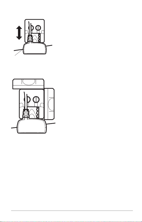
Adjusting the Transducer
Mounting Position
seam aligned with boat hull
Figure 22
Leveling the Mounting
Assembly Horizontally
level
Figure 23
6. Adjust the transducer assembly vertically,
until the seam on the leading edge of the
transducer (the edge closest to the transom
of the boat) is level and just slightly below
the hull (Figure 22).
NOTE: The transducer has a natural downward
slantof 4-5degrees fromleading edge (closest to
the boat transom) to trailing edge (farthest away
from the boat). Looking at the back of the
transducer, the seam should be slightly below
the bottom of the hull.
7. Continue to adjust until the bracket is also
level from port to starboard (horizontally
level as you look at the transducer from
behind the boat [Figure 23]).
8. Mark the correct position on the transom by
level
tracing the silhouette of the transducer
mounting bracket with a pencil or marker.
9. Tighten the pivot bolt,using the pivot screw
and nut to lock the assembly. Hand tighten
only!
CAUTION! Do not use a high speed driver on
thiscombination of fasteners. Hand tighten only.
10. Hand tighten the two mounting screws.
NOTE: You will drill the third mounting hole and
finalize the installation after you route the cable
and test and finish the installation in the
following procedures.
13
Transom Transducer Installation
 Loading...