

Page 1
I-1
Two components need to be installed on the boat: the transducer
and the control head. The control head displays sonar information, the transducer sends and receives sonar signals into the
water. Proper installation of each insures best performance of the
Piranha and provides the greatest enjoyment and functionality.
Due to the wide variety of boats only general instructions
are presented in this installation guide. Each boat has
unique characteristics that need to be evaluated.
INSTALLING THE TRANSDUCER
STEP 1: DETERMINE TRANSDUCER LOCATION
Consider the following to find the best location on the transom:
Choose an area free of turbulent water.
• Turbulence is generated as the boat moves through the
water and is confined to area aft of ribs, strakes and
rivet lines on the bottom of hull. Choose a location on
the transom where the hull forward of this location is
smooth, flat and free of protrusions or ribs.
•Turbulence is also created by the prop - try to keep at
least 380mm (15") from the prop(s).
• The best method to locate areas free of turbulence is
to watch the transom while the boat is moving. For best
high-speed performance this is recommended. Have
an assistant pilot the boat and use caution!
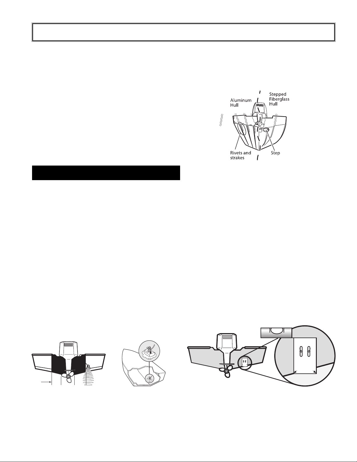
• Stepped hulls require the transducer be mounted on
the step if possible. Never mount the transducer on the
transom behind the step.
• If propellers are forward of the transom, clear water
may be impossible to find. A different transducer or
mounting method should be considered, (see optional
inside hull instructions below).
• The mounting area must be in contact with the water
when the boat is on plane.
• If the boat is trailered, make sure that the transducer is
not inline with trailer bunks or roller assembles that
could damage the transducer during loading
operations.
STEP 2: FOR TRANSOM MOUNTING: DRILL THE
MOUNTING HOLES
1. Remove the mounting template from the last page of
Operation Section (Page O-15).This template provides
a means of locating the two mounting holes which
must be drilled.
2. Hold the template on the transom of the boat in the
location where the transducer will be installed. Align
the template vertically with the inside arrow of the
template on the deadrise where the bottom of the hull
meets the transom wall. (Figure 3 ).
3. Using a pencil or punch, mark the location of the two
mounting holes on the transom.
4. Using a 4mm (
⁵⁄₃₂") bit, drill the two holes to a depth of
approximately 25mm (1"). On fiberglass hulls, it is best
to start with a smaller bit and use progressively larger
drill bits to reduce the chance of chipping or flaking the
outer coating.
PIRANHA 3 & 4 INSTALL GUIDE
You will need: Hand drill and various bits, Phillips #2 & 3
drivers, pencil, silicone sealant (for drilled holes), 2-part,
slow cure epoxy for inside hull transducer mounting, 12v
DC power supply, 1 ampere fuse.
15" 15"
Figure 1. Mounting locations include transom and inside hull.
Turbulence
Figure 2, Location of turbulence
DO NOT LET DEADRISE
INTERSECT THIS LINE
PLACE EITHER CORNER
ON DEADRISE ANGLE
TOP
Use 5/32" drill bit
Drill Drill
PLACE EITHER ARROW
ON DEADRISE ANGLE
TOP
Use 5/32" drill bit
DrillDrill
Level
Figure 3
Page 2
I-2
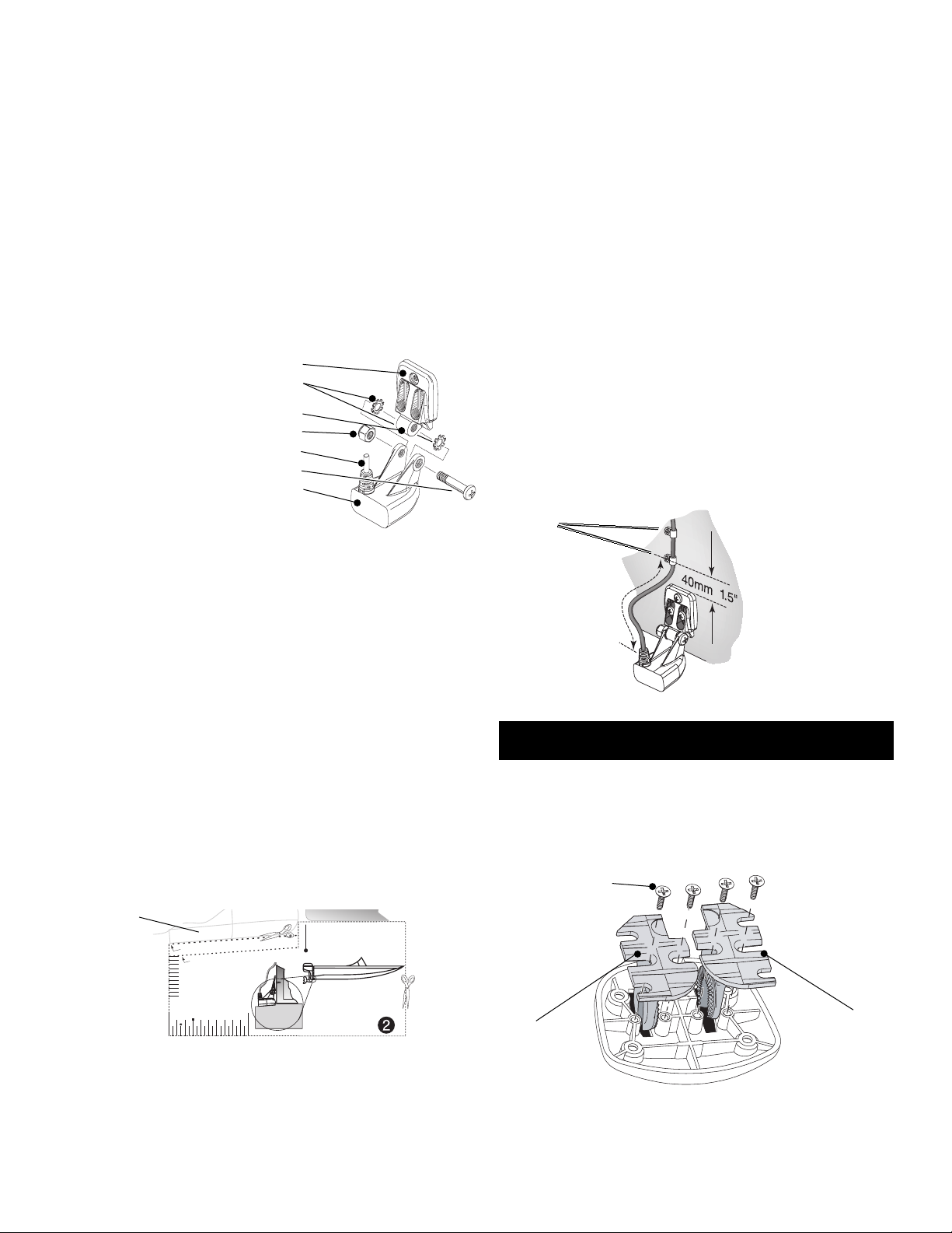
STEP 3: ASSEMBLE & MOUNT THE TRANSDUCER
1. Attach the Transducer Body to the Bracket using the
hardware shown below.
2. Tighten the Pivot Bolt just enough so the transducer
can rotate, but remain in a place when released.
3. Apply silicone sealant into the drilled mounting holes.
4. Align the transducer with the mounting holes and
attach with Phillips screws provided.
5. Tighten the Mounting Screws just enough so the
transducer can move vertically, but remain in a place
when released.
Note: A third mounting screw location is provided in the
mounting bracket. Drill and install this ONLY after final
testing and adjustments have been made.
STEP 4: ADJUST THE TRANSDUCER
Correct transducer height and running angle settings are
needed to ensure best performance at all boat speeds.
Use the template provided (pg. O-15) to make the initial
setting for most boats. Some boat hulls require adjustments beyond these settings for best performance at
all speeds.
1. Cut out the transducer templates from the Piranha
package printed template insert following the cutting
directions for your boat hull.
2. Adjust the height on the transom and the pivot bolt
angle to match guides on the template as shown.
3. Hand tighten the Pivot Bolt and Mount Screws at this
time. Ensure the height and angle have not changed.
STEP 5: ROUTE THE CABLE
The cable must be routed to where the control head will
be mounted. Consider the following:
• The easiest method to get the cable into the boat
routes the cable over the transom. The most common
method drills a hole through the transom, above the
water line.
• Once inside the boat, the cable routes through or along
internal conduits and channels.
•Keep the cable as far away as possible from VHF radio
antenna and tachometer cables.
• Do not cut, shorten or lengthen the transducer cable.
• If the cable is too short, extensions are available at
your dealer or direct from Humminbird.
FOLLOW THESE STEPS:
1. Run the cable over the transom or through a 16mm
(
⁵⁄₈") hole drilled well above the water line.
2. If a hole was drilled, fill it with silicone sealant.
3. Secure the cable with clamps as shown. (Figure 6).
INSTALLING THE CONTROL HEAD
STEP 1: ASSEMBLE THE BASE
1. Insert the Mount Arms through the Base.
2. Secure the Mount Arms with the 4 screws provided.
Figure 4
Mounting Bracket
Star lock washers
Pivot
Nut
Cable
Pivot Bolt
¹⁄₄
-20, #3 Phillips Drive
Transducer
Place on bottom of hull
Align with transom.
Cut and use for Fiberglass Hulls
Fiberglass
Aluminum
Transducer
Guide
Transducer bottom
Hull
Cut and use for Aluminum
Hulls
30mm
15mm
Figure 5
Templates supplied locating the transom bracket and
adjusting the transducer’s position.
Transducer
150mm
6"
Figure 6
Note: Allow enough
slack in the cable for
the transducer to
pivot. Route the
cable to side of
the transducer.
Cable Clamps
Right Arm
Arm Screws,4 #6 x ⁷⁄₁₆"
Left Arm
Figure 7
Page 3

I-3
STEP 2: ATTACH THE CONTROL HEAD TO THE BASE
1. Insert the Pivot Bolt through the Pivot Knuckle on the
control head.
2. Thread the Gimbal Knob onto the Pivot Bolt using only
2-3 turns.
3. Align the Pivot Knuckle with the Mount Base Arms and
slide into place until it seats firmly. A slight twist will aid
in seating the unit.
4. Rotate the Control Head to the desired angle and hand
tighten the Gimbal Knob.
Now you can use the assembled Piranha to identify the best
mounting location.
STEP 3: DETERMINE CONTROL HEAD MOUNTING LOCATION
When choosing a mounting location consider the following:
• Power and transducer cables should be installed first
and must reach the control head.Transducer extension
cables are available. The power cable can be
shortened or lengthened with 18 gauge wire.
• If possible, choose a location that provides access
from below so above deck cable length is short, and
the cable’s hole can be covered by the mount base.
• Ensure enough space exists for easy control head
installation and removal and for pivoting through its full
range of motion.
• The mounting area should be well supported to protect
the fishfinder from wave shock and vibration.
• Choose an area that provides good visibility for the
Piranha.
STEP 4: ELECTRICAL CONNECTIONS
A 2m (6’) long power cable is included to supply power to the
fishfinder. You may shorten or lengthen the cable using 18 gauge
multi-stranded copper wire.
CAUTION: Some boats have 24 or 36 volt electric systems.
Be sure your unit is connected to a 12 VDC power supply.
Humminbird is not responsible for over current or over
voltage failures.
The power cable can be connected to the boat’s electrical system at two places: a fuse panel, usually located near the console, or directly to the battery.
If a fuse terminal is available, use crimp-on type electrical connectors (not included) that match the terminal on the fuse panel.
Attach the black wire to ground and the red wire to 12 VDC
power (Figure 10). Be sure to use a one amp fuse in the connection. If you must wire the control head directly to a battery, be
sure to install an inline fuse holder and use a one amp fuse (not
included) for the protection of the unit (Figure 11).
In order to minimize the potential for interference with other
marine electronics a separate power source (such as a second
battery) may be necessary.
STEP 5: INSTALL THE BASE
1. Remove the control head from the mount base by
loosening the gimbal knob and pulling the unit from the
base - a slight twisting motion will help to release it.
Note: It is not necessary to completely remove the gimbal
knob. Unscrew only enough to permit the unit to release.
2. Using the mount base as a template, mark the location
for the mounting holes.
3. Drill the mounting holes using a 3.5mm (
⁹⁄₆₄") bit.
Figure 8
Pivot Bolt
Pivot Knuckle
Gimbal Knob
Figure 9
Cabling can be routed through a
5/8"(16 mm) hole
centered between
the two rear mounting holes of the
base.
GROUND
POSITIVE
Figure 10
Figure 11
5
/
8
"
Page 4

4. Drill a 16mm (⁵⁄₈") hole at the location where the cables
pass through the mounting surface. If access is
possible underneath mounting surface, drill the hole so
the mount base forms a hole cover. See Figure 9 for
location of cable hole under the mount.
5. Pass the transducer and power cables through the
16mm inch hole, leaving about 150mm length above
the surface.
6. Align the mount base with the holes and attach with the
Phillips screws provided.
STEP 6: ATTACH THE CONTROL HEAD AND PLUG IN CONNECTORS
1. Mount the control head to the base.
2. With attention to shape and orientation of the plugs,
insert the transducer and power cable into the correct
socket according to the figure below.
3. With the control head in place, tilt the unit through its
full range to ensure enough cable slack is left for
movement. Hand tighten the gimbal knob when at its
desired position.
YOUR NEW HUMMINBIRD IS NOW READY FOR OPERATION!
TEST & COMPLETE INSTALLATION
Testing should be performed with the boat in the water, however,
you can initially confirm basic operation with the boat trailered.
Press POWER-MENU once to turn the unit on. An audible chirp
sounds any time a button is pressed. If the unit does not power
on, ensure the cable plugs are fully seated and there is power
available.
The first screen indicates either Start-Up or Simulator. If the unit
detects the transducer, Start-Up will be the default selection. If
no transducer is detected, Simulator will be selected. Use the
Arrow keys to change between Start-Up and Simulator.
Note: The transducer must be submerged in water for
reliable transducer detection.
If the transducer is detected, after several seconds the Piranha
will begin operation unless you choose another option. If the
boat is in the water sonar data begins to scroll across the
screen.
If the bottom is visible on-screen with digital depth readout the
unit is working properly. If no bottom is visible or erratic operation occurs, ensure that the unit is in water greater than 1 meter
(3') and the transducer is fully submerged in water. Remember,
sonar signals can not travel through air.
If the unit is working properly, gradually increase boat speed to
test higher speed performance. If the unit functions well at low
speeds but begins to skip or miss the bottom at higher speeds,
the transducer requires adjustment.
Note: Transducer installation often requires several incremental
adjustments before optimum high-speed performance is achieved.
To optimize transducer installation, try the following.
• Ensure the transducer is NOT located in an area of
turbulent water.
• First, incrementally lower the running depth by 1.5mm
(
¹⁄₁₆") until best high-speed performance is achieved.
• If the bracket is fully extended and high-speed
performance continues to need adjustment,
incrementally change the Pivot Angle to lower the rear
of the transducer by 3mm (
¹⁄₈") steps until best high-
speed performance is achieved.
Important: For transom mount transducers,install the third
mounting screw after final transducer adjustments. Hand
tighten only!
OPTIONAL INSIDE HULL TRANSDUCER MOUNTING
Inside the hull installation requires the control
head to be installed and operational. Inside the hull mounting
generally produces good results in
single thickness fiberglass-hulled
boats.
Note: Transducers with integral
temperature sensors will not
provide accurate temperature
readings when mounting in a hull.
Humminbird cannot guarantee depth performance when transmitting and receiving through the hull of the boat, since some
signal loss occurs. The amount of loss depends on hull construction, hull thickness and the installation.
This installation requires slow-cure two-part epoxy. Do not use
silicone or any other soft adhesive to install the transducer, as
this material reduces the sensitivity of the unit. Five minute
epoxy has a tendency to cure before all the air bubbles can be
purged.
I-4
Figure 13
Transducer Power Temperature
Page 5

I-5
STEP 1: INSTALL THE CONTROL HEAD
Follow directions above for installing the control head.
STEP 2: DETERMINE THE MOUNTING LOCATION
Begin the transducer installation by determining where inside
the hull to install the transducer. Consider the following to find
the best location:
• Observe the outside of the boat hull to find the areas
that are mostly free from turbulent water. Avoid ribs,
strakes and other protrusions as these create
turbulence (Figure 2).
• As a general rule, the faster the boat can travel, the
further aft and closer to the centerline of the hull the
transducer has to be located to remain in contact with
the water at high speeds (Figure 13).
STEP 3: TEST THE MOUNTING LOCATION
There is no opportunity for adjustment after the transducer is
glued in place. Therefore, it is best to perform a trial installation
on inside the hull transducers first, and run the boat at high
speeds to determine the best mounting area.
1. At the identified mounting location, lay the transducer
body face down with the pointed end towards the bow.
2. Fill the hull with enough water to submerge the
transducer body. Use a sand filled bag or other heavy
object to hold the transducer in position.
The transducer cannot transmit through air. The water
purges any air from between the transducer and the
hull, and fills any voids in the coarse fiberglass surface.
3. Power up the Control Head.
4. Run the boat at various speeds and water depths while
observing the screen on the Control Head. If the unit
functions well at low speeds but begins to skip or miss
the bottom at higher speeds, the transducer needs to
be moved. If depth performance is required, test the
fishfinder in water at the desired depth. Test different
locations in the hull until the optimum performance is
achieved.
STEP 4: PERMANENTLY MOUNT THE TRANSDUCER
1. Once the mounting location is determined, mark the
position of the transducer.
2. Remove the water from inside the hull and thoroughly
dry the mounting surface. If the surface is excessively
rough, it may be necessary to sand the area to provide
a smooth mounting surface.
Make sure the mounting area is clean and dry.
3. Mix an ample quantity of two-part slow-cure epoxy
slowly and thoroughly. Avoid trapping air bubbles.
4. Coat the face of the transducer and the inside of the
hull.
5. Press the transducer into place with a slight twisting
motion to purge any trapped air from underneath,
keeping the pointed end of the transducer body
pointed forward (Figure 14).
6. Weight the transducer so it does not move while the
epoxy is curing.
When the epoxy cures, no water is necessary inside the hull.
Neither water, spilled gasoline, nor oil will affect the performance of the transducer.
Figure 14
 Loading...