

Page 1
ONIX8 and ONIX10
Installation Guide
TABLE OF CONTENTS
Introduction . . . . . . . . . . . . . . . . . . . . . . . . . . . . . . . . . . . . . . . . . 1
Install the Control Head . . . . . . . . . . . . . . . . . . . . . . . . . . . . . . . 2
Install the Transducer. . . . . . . . . . . . . . . . . . . . . . . . . . . . . . . . . 4
Route the Cables. . . . . . . . . . . . . . . . . . . . . . . . . . . . . . . . . . . . 16
Connect the Transducer Cable . . . . . . . . . . . . . . . . . . . . . . . . 17
Install Accessories . . . . . . . . . . . . . . . . . . . . . . . . . . . . . . . . . . 17
Connect the Control Head Power Cable . . . . . . . . . . . . . . . . 19
Test and Finish the Installation . . . . . . . . . . . . . . . . . . . . . . . 20
Power On the Control Head . . . . . . . . . . . . . . . . . . . . . . . . . . . 22
Setup Guide . . . . . . . . . . . . . . . . . . . . . . . . . . . . . . . . . . . . . . . . 22
Set Up the Control Head . . . . . . . . . . . . . . . . . . . . . . . . . . . . . . 26
Manage Your Control Head . . . . . . . . . . . . . . . . . . . . . . . . . . . 30
NMEA Input/Output . . . . . . . . . . . . . . . . . . . . . . . . . . . . . . . . . . 31
Specifications . . . . . . . . . . . . . . . . . . . . . . . . . . . . . . . . . . . . . . 34
Maintenance . . . . . . . . . . . . . . . . . . . . . . . . . . . . . . . . . . . . . . . . 38
Troubleshooting . . . . . . . . . . . . . . . . . . . . . . . . . . . . . . . . . . . . . 39
Side Imaging Transducer Mounting Template . . . . . . . . . . . 41
Contact Humminbird . . . . . . . . . . . . . . . . . . . . . . . . . . . . . . . . 42
532187-1_A
Page 2
THANK YOU!
Thank you for choosing Humminbird®, the #1 name in marine electronics. Humminbird has built its reputation by designing and
anufacturing top-quality, thoroughly reliable marine equipment. Your Humminbird is designed for trouble-free use in even the harshest
m
marine environment. In the unlikely event that your Humminbird does require repairs, we offer an exclusive Service Policy. For complete
details, see the separate warranty card included with your unit. We encourage you to read this operations manual carefully in order to get
full benefit from all the features and applications of your Humminbird product.
Contact Humminbird Customer Service at 1-800-633-1468 or visit our Web site at humminbird.com.
WARNING! This device should not be used as a navigational aid to
prevent collision, grounding, boat damage, orpersonal injury. When
the boat is moving, water depth may change too quickly to allow
time for you to react. Always operate the boat at very slow speeds
if you suspect shallow water or submerged objects.
WARNING! The electronic chartin your Humminbird unit is an aid to
navigation designed to facilitate the use of authorized government
charts, not to replace them. Only official government charts and
notices to mariners contain all of the current information needed
for the safety of navigation, and the captain is responsible for their
prudent use.
WARNING! Compass Safe Distance: The control head must be
installed at least 4 feet (1.2 meters) from the compass or other
magnetic equipment on the boat. Also, see your compass
installation guide for details.
WARNING! Humminbird is not responsible for the loss of data files
(waypoints, routes, tracks, groups, recordings, etc.) that may occur
due to direct or indirect damageto the unit’s hardware or software.
It is important to back up your control head’s data files periodically.
Data files shouldalso be saved to your PC before restoring theunit’s
defaults or updating the software. See your Humminbird online
account at humminbird.com and the operations manual on your
Humminbird Manual CD for details.
NOTE: Some features discussed in this manual require a separate
purchase, and some features are only available on international
models. Every effort has been made to clearly identify those
features. Please read the manual carefully in order to understand
the full capabilities of your model.
NOTE: The illustrations in this manual may not look the same as
your product, but your unit will function in the same way.
NOTE: To purchase accessories or any additional equipment for
your control headconfiguration,go to humminbird.com or contact
Customer Service at 1-800-633-1468.
NOTE: The procedures and features described in this manual are
subject to change without notice. This manual was written in
English and may have been translated to another language.
Humminbird is not responsible for incorrect translations or
discrepancies between documents.
WARNING! Disassembly and repair of this electronic unit should
only be performed by authorized service personnel. Any
modification of the serial number or attempt to repair the original
equipment or accessories by unauthorized individuals will void the
warranty.
WARNING! This product contains chemicals known to the State of
California to cause cancer and/or reproductive harm.
WARNING! Do nottravel at high speed with the unit cover installed.
Remove the unit cover before traveling at speeds above 20 mph.
Page 3

Environmental Compliance Statement: It is the intention of Johnson
Outdoors Marine Electronics, Inc. to be a responsible corporate citizen,
operating in compliance with known and applicable environmental
regulations, and a good neighbor in the communities where we make or
sell our products.
WEEE Directive: EU Directive 2002/96/EC “Waste of Electrical and
Electronic Equipment Directive (WEEE)” impacts most distributors,sellers,
and manufacturers of consumer electronics in the European Union. The
WEEE Directive requires the producer of consumer electronics to take
responsibility for the management of waste from theirproducts to achieve
nvironmentally responsible disposal during the product life cycle.
e
WEEE compliance may not be required in your location for electrical &
electronic equipment (EEE), nor may it be required for EEE designed and
intended as fixed or temporary installation in transportationvehicles such
as automobiles, aircraft, and boats. In some European Union member
states, these vehicles are considered outside of the scope of the Directive,
and EEEfor those applications can be considered excluded fromthe WEEE
Directive requirement.
This symbol (WEEE wheelie bin) on product indicates the product
must not be disposed of with other household refuse. It must be
disposed of and collected for recycling and recovery of waste EEE.
Johnson Outdoors Marine Electronics, Inc. will mark all EEE
products inaccordance with the WEEE Directive.It is ourgoal to complyin
the collection, treatment, recovery, and environmentally sound disposal
of those products; however, these requirements do vary within European
Union member states. For more information about where you should
dispose of your waste equipment for recycling and recovery and/or your
European Union member state requirements, please contact your dealer
or distributor from which your product was purchased.
ATTENTION INTERNATIONAL CUSTOMERS: Products sold in the U.S.
are not intended for use in the international market. Humminbird
nternational units provide international features and are designed
i
to meet country and regional regulations. Languages, maps, time
zones, units of measurement, and warranty are examples of
features that are customized for Humminbird international units
urchased through our authorized international distributors.
p
To obtain a list of authorized international distributors, please visit
our Web site at humminbird.com or contact Customer Service at
(334) 687-6613.
ROHS Statement: Product designed and intended as a fixed installation
or part of a system in a vessel may be considered beyond the scope of
Directive 2002/95/EC of the European Parliament and of the Council of 27
January 2003 on the restriction of the use of certain hazardous
substances in electrical and electronic equipment.
360 Imaging™, Cross Touch™, Down Imaging®, DualBeam PLUS™, Humminbird®, i-Pilot®, ONIX™, and Side Imaging® are trademarked by or registered trademarks of
Johnson Outdoors Marine Electronics, Inc.
Adobe, Acrobat, Adobe PDF, and Reader are either registered trademarks or trademarks of Adobe Systems Incorporated in the United States and/or other countries.
Navionics® Gold and Navionics® Classic Charts are trademarked by or registered trademarks of Navionics®.
C-MAP® by Jeppesen is a registered trademark of Jeppesen Marine, Inc.
NMEA 2000® is a registered trademark of the National Marine Electronics Association.
© 2013 Johnson Outdoors Marine Electronics, Inc. All rights reserved.
Page 4

Page 5
INTRODUCTION
This manual will guide you through the following installation requirements:
• Installing the Control Head
Installing the Transducer
•
• Connecting Cables to the Control Head
• Connecting the Control Head to Power
• Powering On the Control Head
• Configuring the Control Head and Basic System Setup
PREPARATION
Before you start the installation, please take a moment to familiarize yourself with the parts
list and supplies list. We also encourage you to read the instructions beforehand so that you
may understand the installation requirements.
NOTE: Product supplies and features are subject to change without notice.
Parts
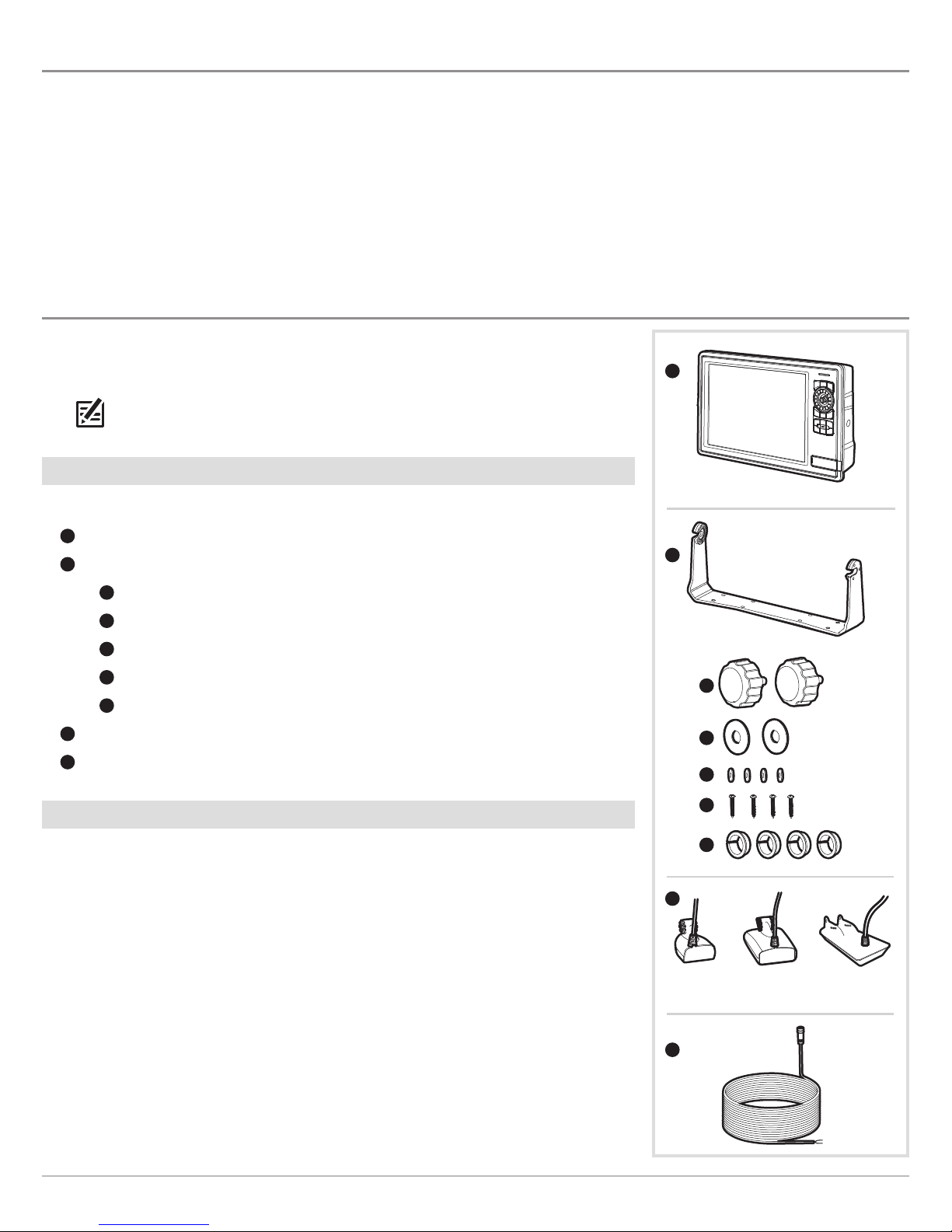
Your ONIX includes the following items:
A
A
ONIX control head with cover
B
gimbal mounting bracket with gimbal mounting hardware
C
(2) gimbal knobs
D
(2) urethane washers
E
(4) flat washers
F
(4) 1" - #10 wood screws
G
(4) 1" - split ring cable grommets
H
(1) transducer with transducer mounting hardware
I
power cable
Supplies
In addition to the parts supplied with your installation kit, you will need the following items:
• powered drill with various drill bits
• various hand tools, including
a socket wrench or flat blade screwdriver
ruler, straightedge, or measuring tape
level
12" plumb line (weighted string or monofilament line)
B
C
D
E
F
G
H
OR OR
DualBeam PLUS
transducers
Side Imaging
transducer
• marker or pencil
• safety glasses
• dust mask
• marine-grade silicone sealant
• dielectric grease (optional)
I
1
Introduction
Page 6
Traditional Gimbal Mount
INSTALL THE CONTROL HEAD
Use the instructions in the following section to gimbal mount the control head on your boat.
NOTE: If you prefer to mount theHumminbird control head overhead, follow theinstructions
in thissection and install the gimbal bracketabove the control head (see Install the Gimbal
Bracket: Overhead Mount). Overhead and/or thin panels may require additional hardware
(separate purchase required) to securely mount the control head.
|
1
Determine the Mounting Location
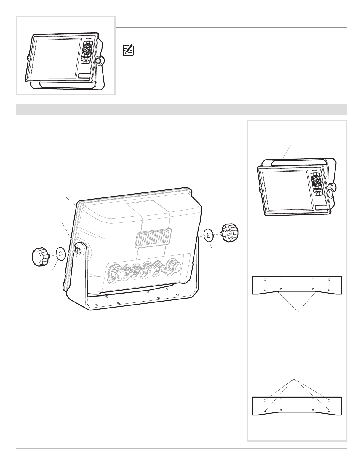
Pre-assemble the control head to plan the best mounting location.
1. Place one urethane washer on one of the gimbal knobs. Thread the gimbal knob and
washer into the control head housing and tighten using 2-3 rotations. This will allow the
knob to stay in place while leaving adequate space to install the control head into the
bracket in the proceeding steps. See the illustration Assembling the Control Head.
2. Repeat step 1 for the other side of the control head.
Assembling the Control Head
front of
control head
Optional Gimbal Mount: Overhead
Flip bracket to the top
of the control head.
opening on
bracket arm
gimbal knob
urethane
washer
gimbal knob
urethane
washer
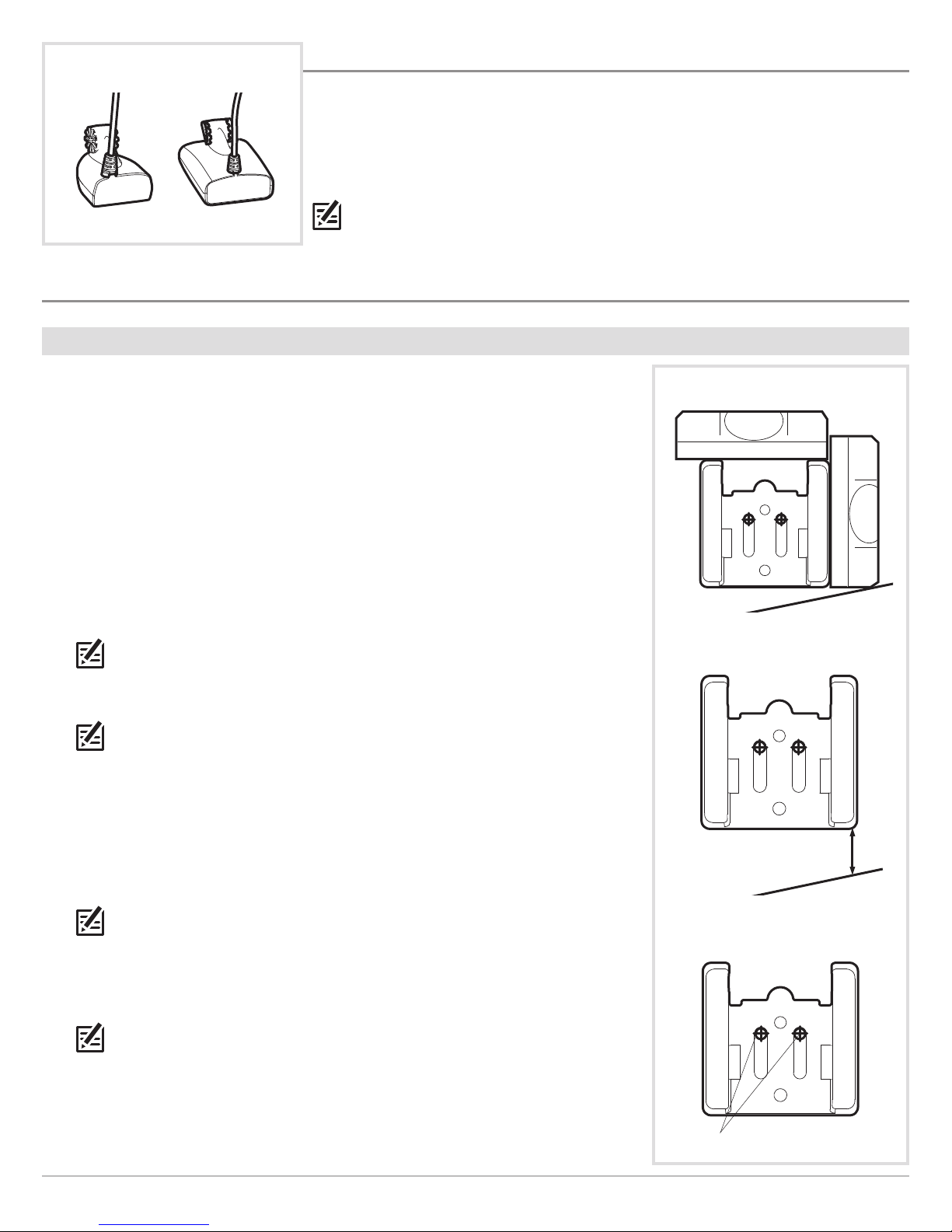
3. Install the control head into the arms of the bracket mount. Confirm the front of the
gimbal bracket is aligned with the front of the control head (see the illustration Gimbal
Bracket).
4. Hand-tighten the gimbal knobs to secure the control head to the gimbal bracket.
5. Place the assembled control head in various locations to determine the best mounting
location.
Consider the following when choosing a mounting location:
front of control head
Gimbal Bracket
Angled corners indicate
the front of the bracket.
Gimbal Bracket: Mounting Holes
outer screw holes
(recommended)
• The mounting area should allow sufficient room (approximately 2 to 4 inches [50.8
to 101.6 mm]) behind the chosen location to drill up to four 1-inch (25.4 mm) holes
for the cables to pass through.
• The mounting surface should be stable enough to protect the control head from
excessive wave shock and vibration.
• The mounting area should allow sufficient room so the control head can pivot
through its full tilt range.
Install the Control Head
front of bracket
2
Page 7
• The mounting location should allow for visibility during
operation, as well as easy installation and removal.
• You must have access, either above or below the
ounting surface, to pass the cables through to the
m
control head.
6. Test route the appropriate cables (power, accessory, etc.) to
the control head mounting location. If the cables are too
short for your application, extension cables are available.
Contact Customer Service for information.
|
3
Install the Gimbal Bracket
Refer to the section that applies to your installation and perform
he procedures to install the gimbal bracket.
t
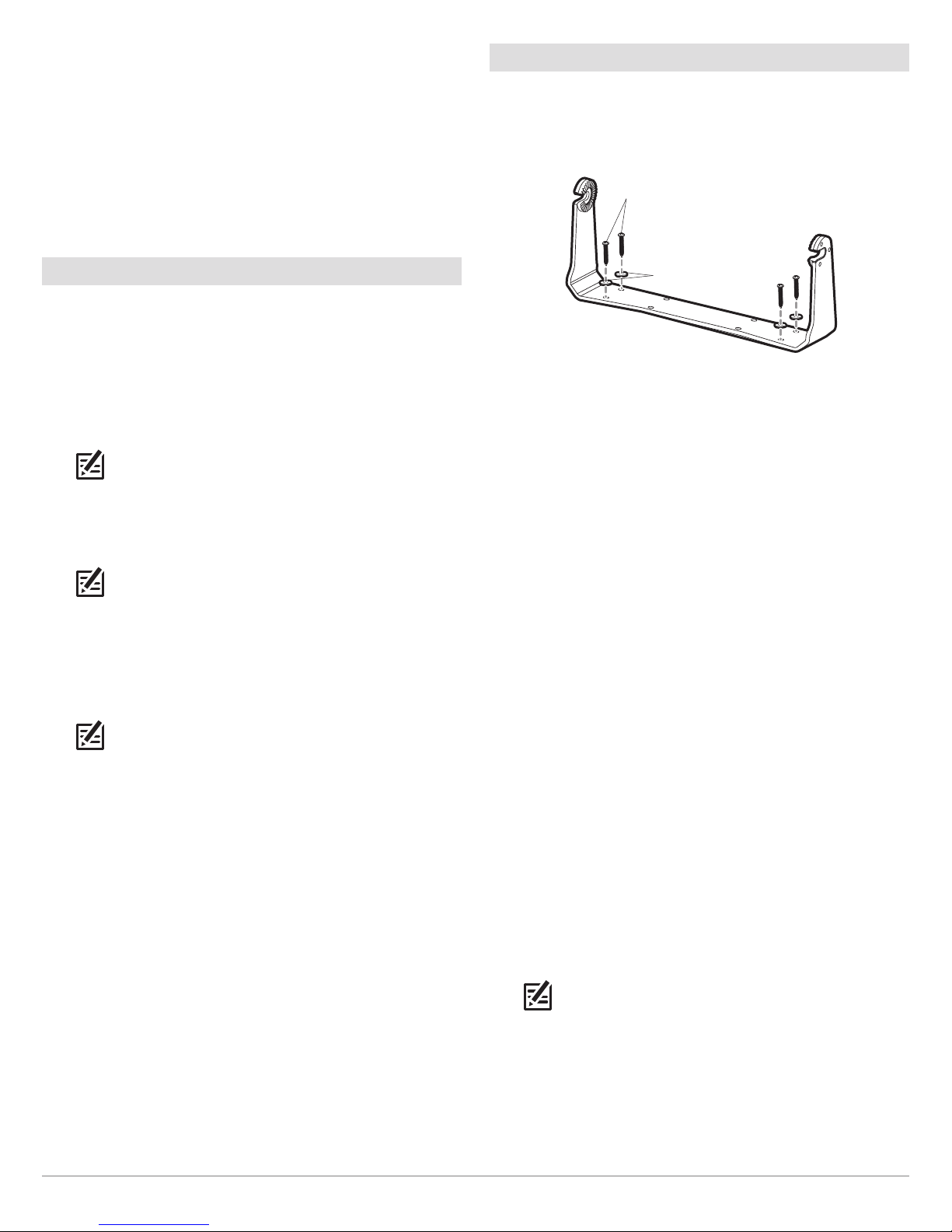
Installing the Gimbal Bracket
wood screws
|
2
Drill the Mounting Holes
1. Loosen the gimbal knobs and remove the control head from
the gimbal bracket.
2. Place the gimbal bracket in the chosen position on the
mounting surface and mark the four outer screw locations
using a pencil or center punch (see the illustration Gimbal
Bracket: Mounting Holes). Confirm the front of the bracket is
facing forward.
NOTE: The outer mounting holes are recommended.
You may use the interior mounting holes if necessary.
3. Set the gimbal bracket aside. Select an appropriately sized
drill bit for the #10 wood screws and drill four pilot screw
holes.
NOTE: When drilling holes in fiberglass, start with a
smaller bit and use progressively larger drill bits to
reduce the chance of chipping the outer coating.
4. Mark and drill a 1-inch (25.4 mm) diameter hole that will
allow you to run the cables close to the mounting bracket.
This hole should be centered approximately 2 to 4 inches
(50.8 to 101.6 mm) from the back of the control head.
NOTE: Your installation may require additional cable
holes. Mark and drill up to four holes according to the
instructions in step 4.
5. Insert the plastic cable grommets (included) to smooth the
hole edges and prevent damage to the cables.
flat washers
Traditional Mount
1. Place the bracket on the mounting surface aligned with the
drilled holes and fill the holes with marine-grade silicone
sealant.
2. Place one flat washer on each wood screw and install the
wood screws into the four mounting holes (see the
illustration Installing the Gimbal Bracket).
3. After all four screws are in place, tighten each screw until
secure.
4. Place the control head back onto the gimbal bracket (see
Determine the Mounting Location for details). Adjust the
control head viewing angle as needed and tighten the gimbal
knobs until the assembly is secured.
Overhead Mount
1. Place the bracket on the mounting surface aligned with the
drilled holes. Fill one hole with marine-grade silicone
sealant.
2. Place one flat washer on a wood screw and install the wood
screw into the hole (see the illustration Installing the Gimbal
Bracket). Repeat for the remaining three holes.
3. Tighten each screw until it is secure.
4. Place the control head back onto the gimbal bracket (see
Determine the Mounting Location for details). Adjust the
control head viewing angle as needed and tighten the gimbal
knobs until the assembly is secured.
NOTE: Overhead and/or thin panels may require
additional hardware (separate purchase required) to
securely mount the control head.
3
Install the Control Head
Page 8
INSTALL THE TRANSDUCER
Review the transducer installation options and the transducer mounting requirements in the following sections. Then proceed to the
nstallation section for your transducer type as follows:
i
• DualBeam PLUS Transducer
• Side Imaging Transducer
NOTE: If the included transducer will not work for your application, you can exchange it, NEW and UNASSEMBLED, with the transducer
mounting hardware included, for a transducer appropriate for your application. This offer applies to the DualBeam PLUS transducer only.
Visit humminbird.com for more information or call Customer Service at 1-800-633-1468.
TRANSDUCER INSTALLATION OPTIONS
Your ONIX control head includes either a DualBeam PLUS transducer or a Side Imaging transducer. Depending on your transducer type,
there are different options available for mounting the transducer on the boat. Review the transducer installation options below.
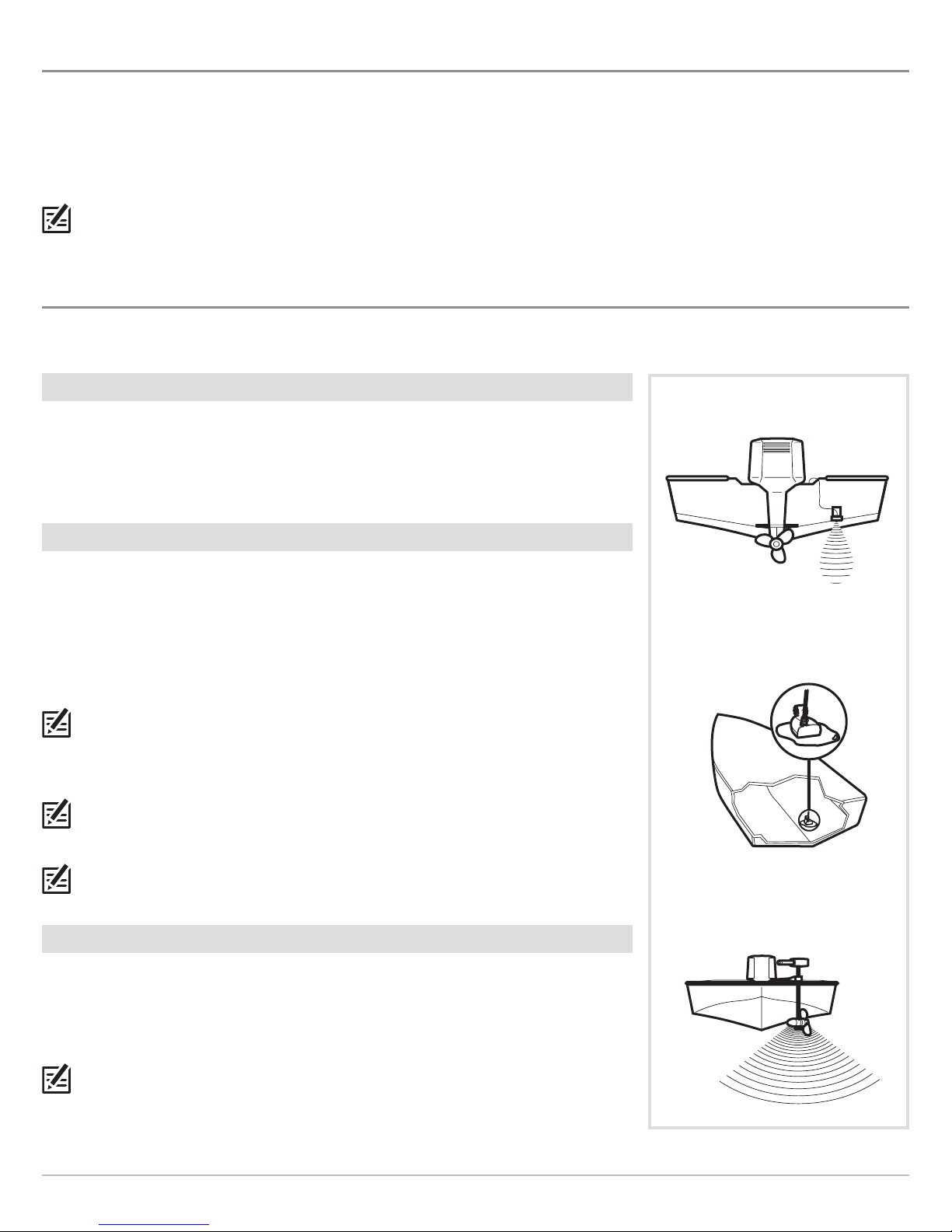
Transom Transducer Installation
Available for the DualBeam PLUS transducer and the Side Imaging transducer.
Your transducer includes the transom mounting hardware. See Transom Transducer
Installation for additional information.
In-Hull Transducer Installation
Available for the DualBeam PLUS transducer only.
In-hull mounting generally produces good results in single thickness, fiberglass-hulled boats.
See DualBeam PLUS Inside the Hull Installation for installation instructions.
Humminbird cannot guarantee depth performance when transmitting and receiving through
the hull of the boat, since some signal loss occurs. The amount of loss depends on hull
construction and thickness, as well as the installation position and process.
NOTE: This installation requires slow-cure two-part epoxy. Do not use silicone or any other
soft adhesive to install the transducer, as this material reduces the sensitivity of the unit. Do
not use five-minute epoxy, as it has a tendency to cure before all the air bubbles can be
purged, thus reducing signal strength.
NOTE: The integral temperature probe will not work with in-hull mounting, so you may want
to consider purchasing a Temperature/Speed accessory, a Temp Sensor, or obtaining a
different transducer.
Transom Transducer Installation
In-Hull Transducer Installation
NOTE: In-hull mounting requires an installed and operational control head.
Trolling Motor Transducer Installation
Available for the DualBeam PLUS transducer and the Side Imaging transducer.
You can purchase a Trolling Motor Adapter kit that will allow you to mount the transducer on
the trolling motor. If you already have a trolling motor bracket, refer to the separate installation
instructions that are included with the bracket.
NOTE: Visit our Web site at humminbird.com for more information, or call Customer Service
at 1-800-633-1468 for details and pricing.
Install the Transducer
4
Trolling Motor Transducer Installation
Page 9
Installing theTransom Mount Transducer
TRANSOM TRANSDUCER INSTALLATION
Your ONIX control head includes transom mounting hardware for your DualBeam PLUS or
ide Imaging transducer. Review the mounting requirements in this section, and then proceed
S
to the section for your transducer type to begin the installation.
NOTE: Due to the wide variety of hulls, only general instructions are presented in this
installation guide. Each boat hull represents a unique set of requirements that should be
evaluated prior to installation. It is important to read the instructions completely and
understand the mounting guidelines before beginning installation.
INSTALLATION OVERVIEW
The transom mount installation provides the following:
• Least loss of signal since the transducer is mounted outside the hull.
• Allows adjustment of both running angle and depth after the transducer is mounted, which enables you to tune the installation
for best results.
• The mounting hardware is designed to pivot the transducer body out of the way should the boat strike debris in the water, or when
trailering.
TRANSOM TRANSDUCER MOUNTING REQUIREMENTS
You must first determine the best location on the transom to install the DualBeam PLUS or Side Imaging transducer. Review the
following information to help you identify the best mounting location.
Turbulence
It is very important to locate the transducer in an area that is relatively free of turbulent
water. Consider the following to find the best location with the least amount of turbulence:
Turbulence: As the boat moves through the water, turbulence is generated by the weight of
the boat and the thrust of the propeller(s) - either clockwise or counterclockwise. This turbulent water is normally confined to areas immediately aft of
ribs, strakes, or rows of rivets on the bottom of the boat, and in the immediate
area of the propeller(s).
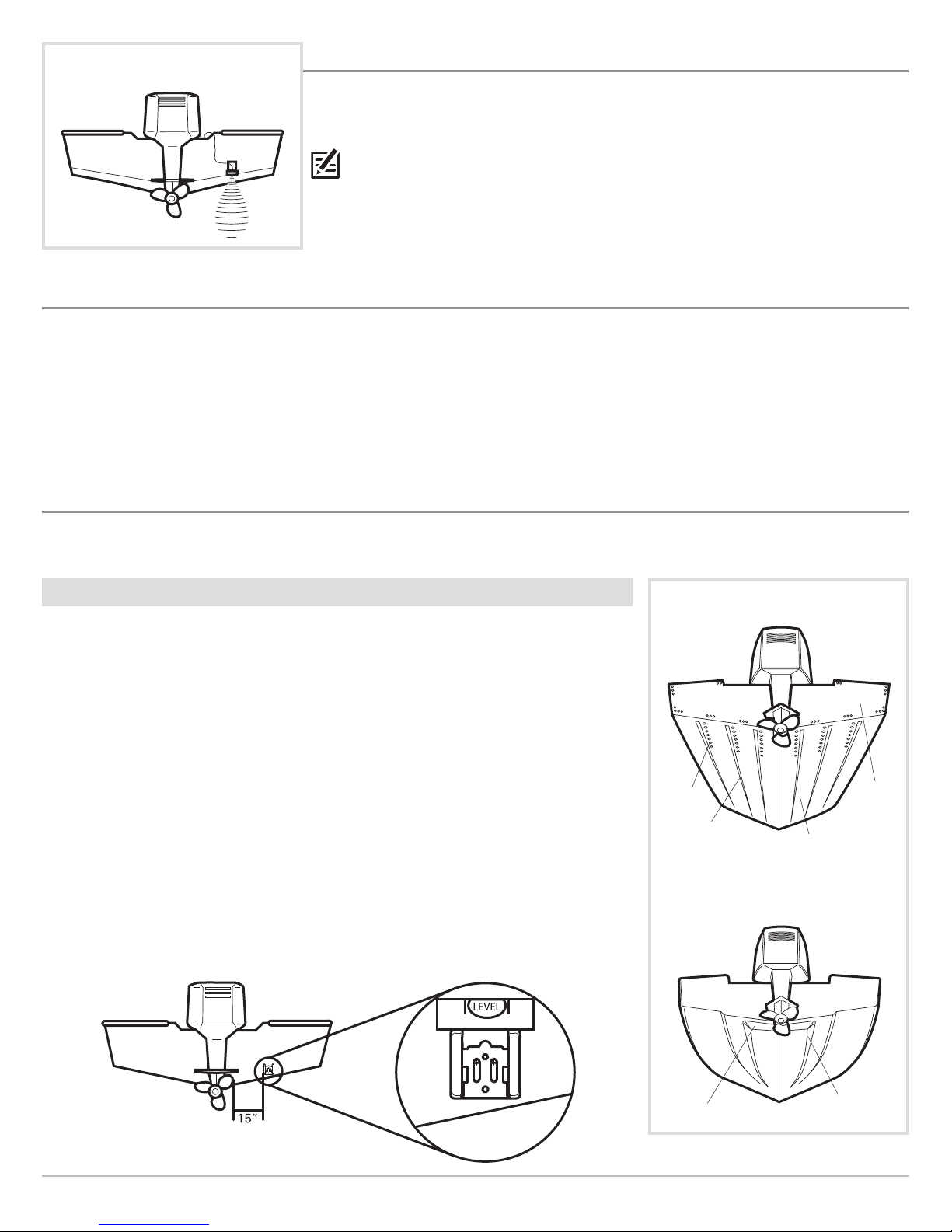
Propellers: Clockwise propellers create more turbulence on the port side. On outboard or
inboard/outboard boats, it may be best to locate the transducer at least 15" to
the side of the propeller(s). The Side Imaging transducer has additional
mounting requirements. See the section Side Imaging Transducer Mounting
Requirements.
If the transom is behind the propeller(s), it may be impossible to find an area
clear from turbulence, and a different mounting technique or transducer type
should be considered.
Find a turbulence-free location that is not in line with trailer bunks or rollers.
Areas of Possible Turbulence
rivets
strakes
Stepped Hull
transom
hull
step
5
Transom Transducer Installation
rib
Page 10
Observation: The best way to locate turbulence-free water is to view the transom while the boat is moving. This method is
recommended if maximum high-speed operation is a high priority. If this is not possible, select a location on the
transom where the hull forward of this location is smooth, flat, and free of protrusions or ribs.
Boat Characteristics
Stepped Hulls: On boats with stepped hulls, it may be possible to mount the transducer on the step. Do not mount the transducer on
he transom behind a step to avoid popping the transducer out of the water at higher speeds. The transducer must
t
remain in the water for the control head to maintain the sonar signal.
Trailering: If you plan to trailer your boat, do not mount the transducer too close to trailer bunks or rollers to avoid moving or
damaging the transducer during loading and unloading of the boat.
High-Speed Operation
DualBeam PLUS Transducer
Traveling over 65 mph with the transducer in the water is not recommended for the 200/50 kHz DualBeam PLUS transom mount
transducer (XNT 14 74 T), as damage might occur. If high-speed operation is critical, you may want to consider using an inside the hull
transducer instead of this transom mount transducer (see DualBeam PLUS Inside the Hull Installation).
Side Imaging Transducer
Side Imaging sonar is best performed at boat speeds from 2 to 6 mph, and is not recommended for high-speed operation as gaps
between strips of information can appear. However, the transducer can support traditional 2D sonar and Down Imaging sonar at higher
speeds (up to 65 mph).
NOTE: The Side Imaging transducer has additional mounting requirements. See the section Side Imaging Transducer Mounting
Requirements.
NOTE: If you require a high-speed application (above 65 mph) and cannot find a transom mount location that will work for your
boat hull, a different mounting technique or transducer type should be considered. See the FAQ (Frequently Asked Questions)
section of our Web site at humminbird.com or call Customer Service at 1-800-633-1468.
Deadrise
DualBeam PLUS Transducer
The hydrodynamic shape of your transducer allows the beam elements to point straight down
without deadrise adjustment.
Side Imaging Transducer
In order for the side beams to be displayed accurately, the transducer must be mounted parallel
with the waterline. This positioning allows the beam elements to point straight down without
deadrise adjustment.
Deadrise
deadrise angle
Transom Transducer Installation
6
Page 11
ualBeam PLUS Transducers
D
INSTALL THE DUALBEAM PLUS TRANSDUCER
Use the procedures in the following sections to install the DualBeam PLUS transducer on
our boat. Your installation choices are as follows:
y
• Transom Mount
• Inside the Hull Mount
200/83 kHz
200/50 kHz
NOTE: Your transducer might not look exactly like the illustrations in this guide, but it will
mount in the same way.
DUALBEAM PLUS TRANSOM MOUNT INSTALLATION
|
1
Prepare the Mounting Location
In this procedure, you will determine the mounting location and drill two mounting holes,
using the transducer mounting bracket as a guide.
1. Confirm you have read the transducer mounting requirements under Transom
Transducer Mounting Requirements.
2. Make sure that the boat is level on the trailer, both from port to starboard and from
bow to stern, by placing your level on the deck of the boat, first in one direction, then in
the other.
3. Hold the mounting bracket against the transom of the boat in the location you have
selected. Align the bracket horizontally using the level. Make sure that the lower corner
of the bracket does not protrude past the bottom of the hull, and there is at least 1/4"
clearance between the bottom of the bracket and the bottom of the transom for
fiberglass boats, and 1/8" clearance for aluminum boats.
NOTE: If you have a flat-bottomed aluminum boat, some additional adjustment may be
needed to accommodate the rivets on the bottom of the boat (in other words, the gap
may need to be a little smaller than 1/8"). This will help you to avoid excessive turbulence
at high speeds.
Positioning the Mounting Bracket
Level
Level
Boat Hull Types Require
Different Mounting Positions
NOTE: If your propeller moves clockwise as the boat moves forward (as you're facing the
stern of the boat from behind), mount the transducer on the starboard side, and align
the bottom right corner of the mounting bracket with the bottom of the boat. If your
propeller moves counterclockwise as the boat moves forward (as you're facing the stern
of the boat from behind), mount the transducer on the port side, and align the bottom
left corner of the mounting bracket with the bottom of the boat.
4. Continue to hold the bracket on the transom of the boat, and use a pencil or marker to
mark where to drill the two mounting holes. Mark the drill holes near the top of each slot,
making sure that your mark is centered in the slot, as shown in the illustration.
NOTE: The third hole should not be drilled until the angle and height of the transducer is
finalized, which you will not do until a later procedure.
5. Make sure that the drill bit is perpendicular to the actual surface of the transom, NOT
parallel to the ground, before you drill. Using a 5/32" bit, drill the two holes only to a
depth of approximately 1".
NOTE: On fiberglass hulls, it is best to use progressively larger drill bits to reduce the
chance of chipping or flaking the outer coating.
1/8" for aluminum
1/4" for fiberglass
Using the Mounting Bracket
to Mark the Initial Drill Holes
mark initial drill holes
7
Install the DualBeam PLUS Transducer
Page 12
|
-
2 -1 012345678910 11 12 13 14 15 16 17 18 19 20 21 22 23 24
Transom Angle (°)
Bead Alignment
Number
142531425
2
5 26 27
3
2
8 29 30
1
Measured Distance (x)
1
.1cm
1
/2“
0
.0 cm
0
“
2
.5 cm
1
“
4
.3 cm
1
5/8“
5
.9 cm
2
3/8“
7
.6 cm
3
“
9
.3cm
3
5/8“
1
1.1cm
4
3/8“
1
2.9cm
5
“
1
4.9cm
5
7/8“
1
6.9cm
6
5/8“
2
Assemble the Transducer and Initial Mounting
In this procedure, you will assemble the transducer using the hardware provided, then mount it and make adjustments to its position
ithout locking it in place.
w
NOTE: You will initially assemble the transducer and the pivot arm by matching the two ratchets to a numbered position on the
transducer knuckle. Further adjustments may be necessary.
Determine Your Transom Angle
1a. If you already know your transom angle, refer to the chart below for the initial position to use to set the ratchets. If your transom
is angled at 14 degrees (a common transom angle for many boats) use position 1 for the ratchets. In either case, go to step 2.
or...
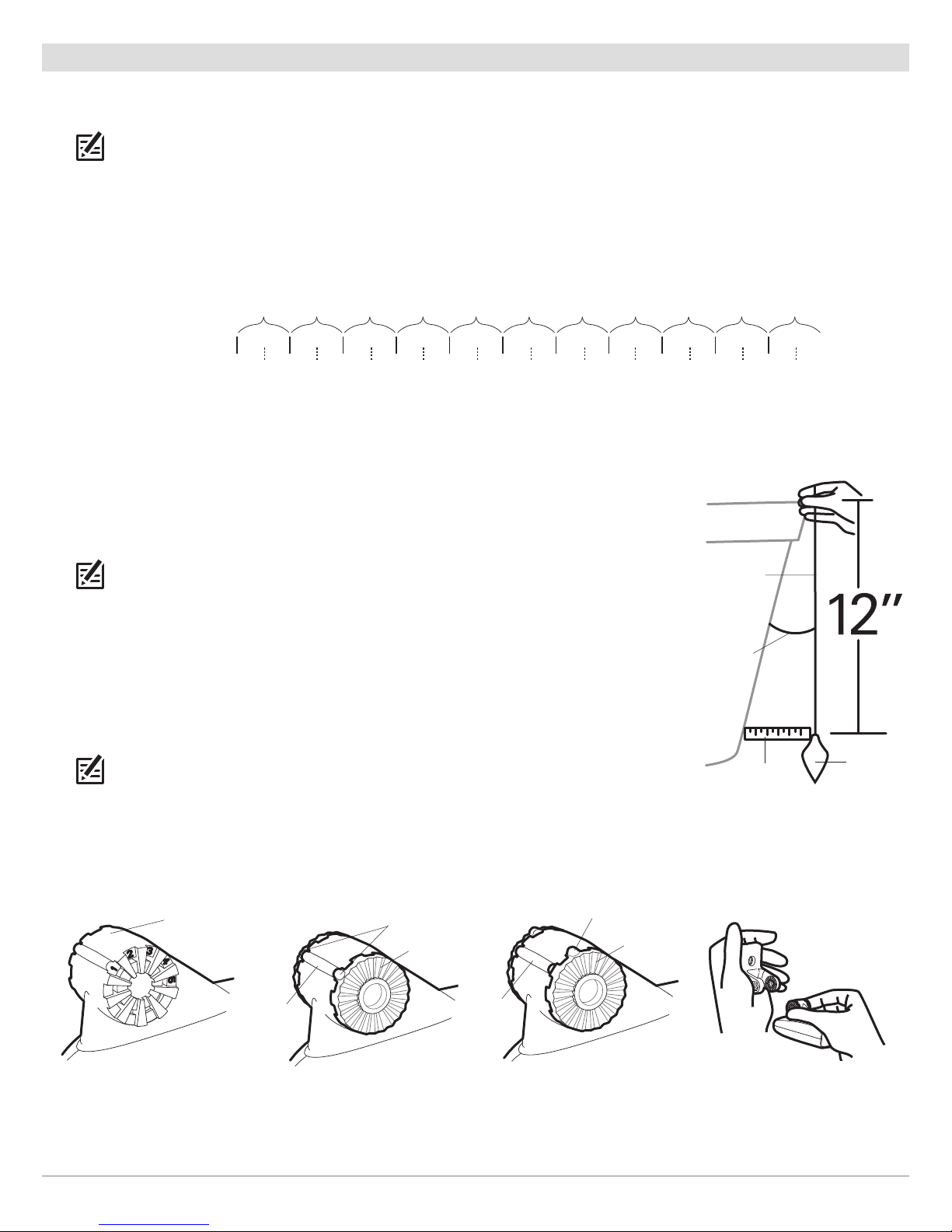
1b. If you do not know your transom angle, measure it using a plumb line (weighted nylon string
or monofilament line) exactly 12 inches long. Hold the top of the plumb line against the top
of the transom with your finger, and wait until the line hangs straight down. Using a ruler,
measure the distance from the bottom of the plumb line to the back of the transom, then
use the chart. Refer to the illustration, Measuring the Transom Angle, for more information.
NOTE: It is important to take your measurement in the location shown in the Measuring the
Transom Angle illustration, from exactly 12 inches down from the top of the transom.
Assemble the Transducer
2. Place the two ratchets, one on either side of the transducer knuckle, so that the beads on
each ratchet line up with the desired position number on the knuckle. If you are setting the
ratchets at position 1, the beads on each ratchet will line up with the rib on the transducer
knuckle to form one continuous line on the assembly.
NOTE: The ratchets are keyed. Make sure that the square teeth on each ratchet face the square
teeth on the transducer knuckle, and the triangular teeth face outward.
3. Hold the ratchets on the transducer knuckle with one hand and fit the pivot arm over them
until it snaps into place with the other hand. Refer to the illustrations below.
Transducer Knuckle Positions
knuckle
Ratchets Placed in Position 1
beads
ratchet
Ratchets Placed in Position 2 Fitting the Mounting
bead
ratchet
Measuring the Transom Angle
plumb line
transom
angle in
degrees (°)
measured
distance (X)
weight
Bracket Over the Ratchet
rib at
position 1
Install the DualBeam PLUS Transducer
rib
8
Page 13
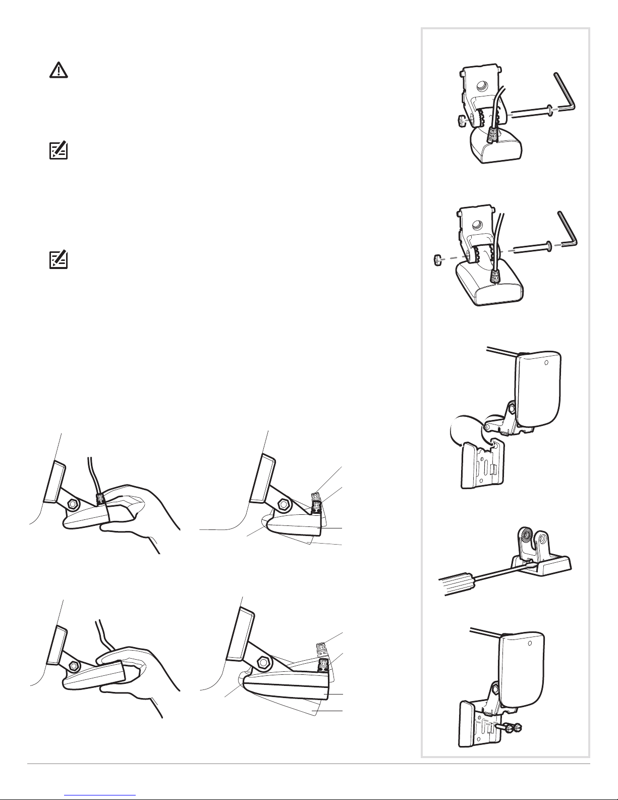
4. Put the pivot bolt through the assembly to hold it in position and loosely install the nut,
but do NOT tighten the nut at this time.
CAUTION! Do not use a high speed driver on this combination of fasteners. Hand-tighten
nly.
o
5. Insert the pivot arm assembly into the mounting bracket as shown in the illustration.
Do NOTsnapthe assemblyclosed,as you willneedto access the mountingbracketin the next
step.
NOTE: If the pivot assembly is snapped closed over the mounting bracket, use a flathead
screwdriver or similar tool to gently pry the assembly away from the mounting bracket.
Mount the Transducer
6. Align the mounting bracket transducer assembly with the drilled holes in the transom.
With a 5/16" socket driver, mount the assembly to the transom using the two #10 - 1"
long screws (provided). Hand-tighten only!
NOTE: Make sure that the mounting screws are snug, but do not fully tighten the
mounting screws at this time to allow the transducer assembly to slide for adjustment
purposes.
7. Snap the pivot arm down into place.
nserting the Pivot Bolt -
I
200/83 kHz Transducer
nserting the Pivot Bolt -
I
200/50 kHz Transducer
Make Adjustments to the Transducer Mounting Position
8. Adjust the initial angle of the transducer from back to front by rotating the transducer
until the side seam on the transducer is almost parallel with the bottom of the boat, one
click at a time in either direction. See the illustration Adjusting the Initial Transducer
Angle.
Adjusting the Initial Transducer Angle - 200/83 kHz Transducer
one click too high
correctly aligned
(transducer side
seam is aligned
with boat bottom)
trailing edge
leading edge
Adjusting the Initial Transducer Angle - 200/50 kHz Transducer
one click too low
Inserting the Pivot Arm Assembly
into the Mounting Bracket
Prying the Assembly Away from
the Mounting Bracket
Mounting the Assembly to the Transom
leading edge
one click too high
correctly aligned
(transducer side
seam is aligned
with boat bottom)
trailing edge
one click too low
9
Install the DualBeam PLUS Transducer
Page 14
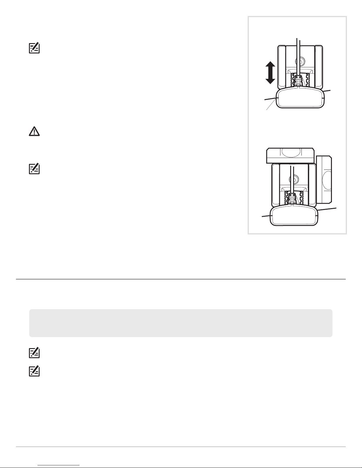
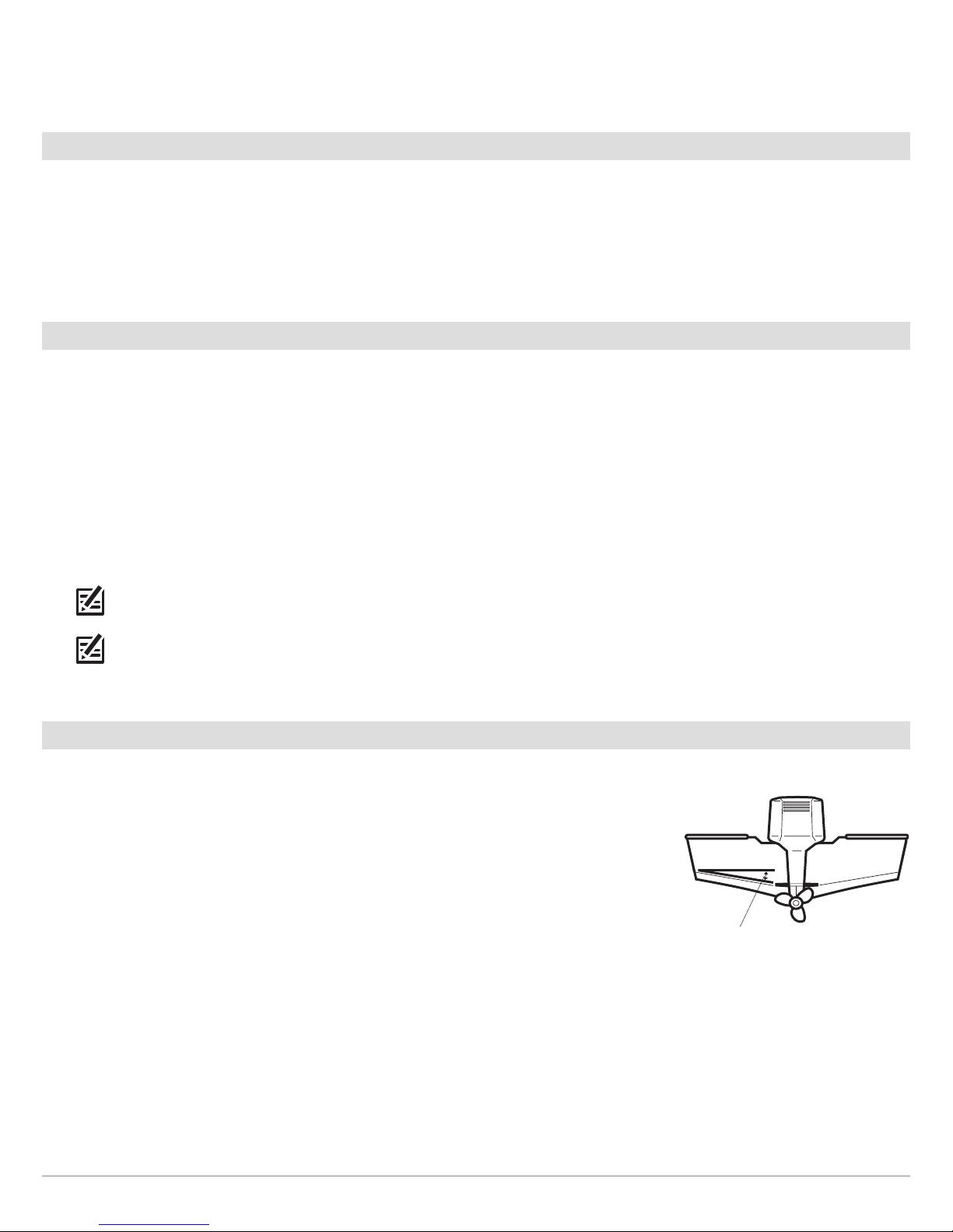
9. Adjust the transducer assembly vertically, until the seam on the leading edge of the
transducer (the edge closest to the transom of the boat) is level and just slightly
below the hull.
NOTE: The transducer has a natural downward slant of 4 to 5 degrees from leading edge
(closest to the boat transom) to trailing edge (farthest away from the boat). Looking at
he back of the transducer, the seam should be slightly below the bottom of the hull.
t
10. Continue to adjust the transducer assembly until the bracket is also level from port to
starboard (horizontally level as you look at the transducer from behind the boat).
11. Mark the correct position on the transom by tracing the silhouette of the transducer
mounting bracket with a pencil or marker.
Adjusting the Transducer
Mounting Position
12. Tighten the pivot bolt, using the pivot screw and nut to lock the assembly. Hand-tighten
only!
CAUTION! Do not use a high speed driver on this combination of fasteners. Hand-tighten
only.
13. Snap open the assembly and hand-tighten the two mounting screws, then snap the
assembly closed.
NOTE: You will drill the third mounting hole and finalize the installation after you route
the cable and test and finish the installation in the following procedures.
Proceed to the section Route the Cables.
DUALBEAM PLUS INSIDE THE HULL INSTALLATION
seam aligned
with boat hull
Leveling the Mounting
Assembly Horizontally
Level
Level
In-hull mounting generally produces good results in single thickness, fiberglass-hulled boats. Humminbird cannot guarantee depth
performance when transmitting and receiving through the hull of the boat, since some signal loss occurs. The amount of loss depends
on hull construction and thickness, as well as the installation position and process.
This installation requires slow-cure two-part epoxy. Do not use silicone or any other soft adhesive to install the transducer, as this
material reduces the sensitivity of the unit. Do not use five-minute epoxy, as it has a tendency to cure before all the air bubbles
can be purged, thus reducing signal strength.
NOTE: The integral temperature probe will not work with in-hull mounting, so you may want to consider purchasing a
Temperature/Speed accessory, a Temp Sensor, or obtaining a different transducer.
NOTE: In-hull mounting requires an installed and operational control head.
Install the DualBeam PLUS Transducer
10
Page 15

|
1
Determine the Transducer Mounting Location
Decide where to install the transducer on the inside of the hull. Consider the following to find
the best location:
• Observe the outside of the boat hull to find the areas that are mostly free from turbulent
ater. Avoid ribs, strakes, and other protrusions, as these create turbulence (see Areas
w
of Possible Turbulence).
• As a general rule, the faster the boat can travel, the further aft and closer to the centerline
of the hull the transducer has to be located in order to remain in contact with the water
at high speeds (see Preferred Mounting Area).
Areas of Possible Turbulence
rivets
transom
|
Trial Installation
2
You will not be able to adjust the mounting after an inside the hull transducer is installed. It is
best, therefore, to perform a trial installation first that includes running the boat at various
speeds, in order to determine the best mounting area before permanently mounting the
transducer.
1. Plug the transducer into the control head, then power up the control head. If the unit
does not power-up, confirm that the cable connectors are properly connected and that
power is available.
2. Setup Guide: See the section Setup Guide for initial start up instructions. You must
complete the steps indicated in the Setup Guide before starting normal operation.
NOTE: After completing the Setup Guide, the control head will automatically enter normal
operation.
3. Press the HOME key .
4. Select a sonar view from the Favorites bar to display on-screen.
NOTE: See your control head operations manual for more information about selecting
views.
5. View the sonar signal at its best by holding the transducer over the side, immersed in the
water, so that it is pointing straight down over a known flat bottom. Use the display to
benchmark against the sonar signal that will be detected once the transducer is placed
in the hull.
strakes
Preferred Mounting Area
In-Hull Transducer Installation -
200/83 kHz Transducer
hull
6. Place the transducer body face down at the identified mounting location inside the hull,
with the pointed end towards the bow (see In-Hull Transducer Installation).
7. Fill the hull with enough water to submerge the transducer body. Use a sand-filled bag or
other heavy object to hold the transducer in position. The transducer cannot transmit
through air, and the water purges any air from between the transducer and the hull, and
fills any voids in the coarse fiberglass surface.
8. View the sonar signal on the display and compare against what was observed in Step 5,
making sure that the boat is in the same location as it was during your observations in
Step 5. If the results are comparable, move on to Step 9. Otherwise, locate a new position
in the hull and repeat Steps 6 through 8.
9. Run the boat at various speeds and water depths while observing the screen on the
control head. If depth performance is required, test the transducer in water at the desired
depth. If the performance is acceptable, move on to Step 10. If the performance is not
acceptable, repeat Steps 6 through 9.
10. Once you have determined the best mounting location using the above steps, mark the
position of the transducer.
In-Hull Transducer Installation -
200/50 kHz Transducer
11
Install the DualBeam PLUS Transducer
Page 16

|
3
Route the Cable
1. Once the mounting location is determined and you have marked the position of the
transducer, route the cable from the transducer to the control head.
|
Permanently Mount the Transducer
4
. Make sure the position of the transducer is marked.
1
2. You may have to disconnect the cable to the control head and reconnect it at the end of
this procedure.
3. Remove the water from inside the hull and thoroughly dry the mounting surface. If the
surface is excessively rough, it may be necessary to sand the area to provide a smooth
mounting surface.
4. Mix an ample quantity of two-part slow cure epoxy slowly and thoroughly. Avoid trapping
air bubbles.
5. Coat the face of the transducer and the inside of the hull with epoxy (see In-Hull
Transducer Installation and Applying Epoxy to the Transducer).
6. Press the transducer into place with a slight twisting motion to purge any trapped air
from underneath, keeping the pointed end of the transducer body pointed forward,
towards the bow (see Installing the Transducer).
NOTE: Proper operation requires the pointed end of the transducer body to face towards
the bow.
Applying Epoxy to the
200/83 kHz Transducer
Applying Epoxy to the
200/50 kHz Transducer
7. Weight the transducer so that it will not move while the epoxy is curing.
NOTE: When the epoxy cures, no water is necessary inside the hull.
NOTE: Neither water, spilled gasoline, nor oil will affect the performance of the
transducer.
Proceed to the section Connect the Transducer Cable.
Installing the 200/83 kHz Transducer
Installing the 200/50 kHz Transducer
Install the DualBeam PLUS Transducer
12
Page 17

Side Imaging Transducer
INSTALL THE SIDE IMAGING TRANSDUCER
Use the procedures in this section to install the Side Imaging transducer on your boat. The
ransducer mounting template is provided at the end of this manual (see Side Imaging
t
Transducer Mounting Template).
OTE: See the Transom Transducer Mounting Requirements before beginning the
N
installation.
SIDE IMAGING TRANSDUCER MOUNTING REQUIREMENTS
Side Imaging Requirements
In addition to the requirements shown in the Transom Transducer
Mounting Requirements section, the Side Imaging transducer has
some special requirements because of its side viewing
capabilities:
• The Side Imaging transducer must NOT have anything
obstructing the ‘view’ of the side looking beams. For
example, nothing can be in the line of sight of these beams
(not a hull, motor, additional transducer, etc.). See the
illustrations below.
NOTE: You may need to tilt the motor up and out of
the way when using the side looking beams.
Transducer Mount Position: Unobstructed View
The jack plate gives the transducer safe distance from the motor
and turbulence. The SideImaging beams havea clear view side-to-side.
Multiple Transducer Installation (optional)
If you have installed or are planning to install a second transducer
in addition to this Side Imaging transducer, you must determine
which transducer will be used as the primary source for traditional
2D sonar when operating the boat at high speeds (up to 65 mph).
There are special mounting requirements for the Side Imaging
transducer depending on if it will be in the water or out of the water
during high-speed operation.
Primary Source - Side Imaging Transducer
If you plan to use the Side Imaging transducer as the primary
source for traditional 2D sonar and Down Imaging sonar during
high-speed operation (up to 65 mph), mount the transducer at
least 15" from the center of the engine with an unobstructed view
on both sides of the transducer (see Side Imaging Requirements
and the illustration Transducer Mount Position: Unobstructed
View).
Primary Source - Secondary Transducer
If you plan to use a second transducer as the primary source for
traditional 2D sonar only during high-speed operation (up to 65
mph), mount the Side Imaging transducer where it will not be in
direct water flow. For this installation, you may install the
transducer less than 15" from the center of the engine. Review
the following mounting alternatives:
Transducer Mount Position: Obstructed View
The transducer is tooclose to motor turbulence,and the Side Imaging view
is blocked by the motor. The view cannot extend from side-to-side.
• The Side Imaging transducer can be mounted on or near the
centerline of the boat and higher on the transom to prevent
direct contact with water flow under the boat at high speeds.
Confirm that the transducer is low enough on the transom to
be submerged in the water at low speeds. It should not come
into contact with the motor when it is raised or lowered.
NOTE: Mounting the Side Imaging transducer higher
on the transom should not create turbulence that
affects the engine’s water intakes. Contact your
dealer to verify your individual boat setup.
• The Side Imaging transducer can be mounted to the jack
plate. Contact your dealer for more information about the
brands of jack plates that will accommodate this type of
installation.
NOTE: A Y-cable or transducer switch may be required
to connect the Side Imaging transducer to the second
transducer. The Y-cable and transducer switch require
separate purchases.
13
Install the Side Imaging Transducer
Page 18

Deadrise
In order for the side beams to be displayed accurately, the transducer must be mounted
•
parallel with the waterline. This positioning allows the beam elements to point straight
own without deadrise adjustment (see the illustration Deadrise).
d
NOTE: Rough seas, high speed, and air bubbles can also affect the reading of the Side
Imaging transducer.
eadrise
D
|
1
Mount the Transducer Bracket
In this procedure you will mount the bracket, using the mounting template provided as a
guide. This template allows you to mark where the mounting holes should be drilled. See
Side Imaging Transducer Mounting Template at the end of this manual.
1. Confirm you have read the transducer mounting requirements under Transom
Transducer Mounting Requirements and Side Imaging Transducer Mounting
Requirements.
2. Cut out the transducer mounting template from the back of this manual (see Side
Imaging Transducer Mounting Template). Match the mounting bracket screw slots to
the template screw slots.
3. Hold the template on the transom of the boat in the location you have selected. Align
the template vertically, matching the lower edge of the transom with the bottom corner
of the template.
NOTE: If your propeller moves clockwise as the boat moves forward (as you're facing
the stern of the boat from behind), mount the transducer on the starboard side, and
use the bottom left corner of the template. If your propeller moves counter-clockwise
as the boat moves forward (as you're facing the stern of the boat from behind), mount
the transducer on the port side, and use the bottom right corner of the template.
4. Continue to hold the template on the transom of the boat, and use a pencil or punch
to mark where to drill the three mounting holes shown on the template.
5. Using a 5/32" bit, drill the three holes only to a depth of approximately 1".
NOTE: On fiberglass hulls, it is best to use progressively larger drill bits to reduce the
chance of chipping or flaking the outer coating.
deadrise angle
Attaching the Bracket
Inserting the Square Nuts
square
nuts
6. Use a marine-grade silicone sealant to fill the drilled holes, especially if the holes
penetrated the transom wall.
7. Align the metal mounting bracket with the mounting holes. The center slot of your
mounting bracket should be above the two outer slots. Insert the three 1" flat head
wood screws into the drilled holes, but do not completely tighten.
NOTE: The mounting bracket and all other hardware supplied is top quality stainless
steel for maximum strength and corrosion protection.
|
2
Assemble the Transducer
In this procedure you will attach the pivot to the transducer using the hardware provided.
1. Attach the pivot to the transducer body as shown in the illustrations using the square
nuts, toothed washers, and two 1/4–20 x 5/8" machine screws. The square nuts will be
prevented from rotating by the pocket in the back of the pivot. The toothed washers
must fit on the inside of the transducer ears, between the pivot and the ears.
NOTE: An Allen wrench is provided which fits all of the 1/4–20 screws, but do not fully
tighten the screws at this time.
Install the Side Imaging Transducer
14
toothed
washer
transducer
ear
Attaching the Pivot
pivot
machine
screw
Page 19

|
3
Attach the Transducer to the Bracket
1. Slide the assembled transducer into the metal bracket from the bottom, aligning the
large hole at the top of the bracket with the hole in the pivot.
2. Insert the headed pin through the pivot holes in the bracket and pivot. The headed pin
can be inserted from either side of the bracket.
3. Place the nylon washer over the opposite end of the headed pin. Place the stainless
washer over the 1/4–20 x 5/8" screw threads, then insert into the opposite end of the
headed pin and finger tighten only. The screw has a thread locking compound on the
threads to prevent loosening, and should NOT be fully tightened until all adjustments
are made.
|
4
Adjust the Running Position
The running position of the transducer is now completely adjustable. Subsequent adjustment
may be necessary to tweak the installation after high speed testing. The mounting bracket
allows height and tilt adjustment; the machine screws allow angle adjustment.
NOTE: Side Imaging is best performed at boat speeds from 2 to 6 mph. If the boat is
stationary, the same information is displayed over and over. If the boat is moving too
quickly, there will be gaps between the strips of information. The best boat speed to use
will depend on the side range selected. Slower speeds are good for longer ranges, while
faster speeds can be used at shorter ranges.
1. Adjust the angle of the transducer body first, so it is parallel with the hull of the boat.
Fully tighten the two machine screws using the supplied Allen wrench. Access the
machine screws through the lower holes in the side of the mounting bracket.
Attaching the Transducer
to the Bracket
allen wrench
nylon washer
(fits over headedpin)
screw
stainless washer
(fits over screwthreads)
Tightening the Machine Screws
allen wrench
metal bracket
headed pin
pivot
2. Next, adjust the height of the assembly so the face of the transducer is 1/8" to 1/4"
beneath the bottom of the transom, and fully tighten the three mounting screws. To
access the mounting screws, pivot the transducer assembly up into the bracket as
shown in the illustration Tightening the Mounting Screws.
CAUTION! Be careful not to alter the running angle, as some force is necessary to pivot
the assembly.
3. If access to the top mounting hole is not possible due to the selected height of the
transducer, fully tighten the two lower screws. Remove the headed pivot pin and the
transducer assembly, tighten the top screw, and then reassemble.
4. Confirm that the pivot angle has not changed and that all mounting screws are fully
tightened.
Proceed to the section Route the Cables.
machine screw holes
Tightening the Mounting Screws
Pivot the
transducer
assembly up
to tighten the
mounting
screws.
15
Install the Side Imaging Transducer
Page 20

Routing the Cables
ROUTE THE CABLES
Use the procedures in the following section to route and connect all cables to the control
ead.
h
CAUTION! Do NOT mount the cables where the connectors could be submerged in water
or flooded. If cables are installed in a splash-prone area, it may be helpful to apply
dielectric grease to the inside of the connectors to prevent corrosion. Dielectric grease
can be purchased separately from a general hardware or automotive store.
CAUTION! Do not cut or shorten the transducer cable, and try not to damage the cable
insulation. Route the cable as far as possible from any VHF radio antenna cables or
achometer cables to reduce the possibility of interference. If the cable is too short,
t
extension cables are available to extend the transducer cable up to a total of 50'. For
assistance, contact Customer Service at humminbird.com or call 1-800-633-1468
for more information.
Route the Transducer Cable
The transducer cable has a low profile connector, which must be routed to the point where the
control head is mounted. There are several ways to route the transducer cable to the area
where the control head is installed. The most common procedure routes the cable through
the transom into the boat.
NOTE: Your boat may have a pre-existing wiring channel or conduit that you can use for
the transducer cable.
1. Unplug the other end of the transducer cable from the control head. Make sure that the
cable is long enough to accommodate the planned route by running the cable over the
transom.
NOTE: The transducer can pivot up to 90 degrees in the bracket. Allow enough slack in
the cable for this movement. It is best to route the cable to the side of the transducer
so the transducer will not damage the cable during movement.
2a. If you are routing the cable over the transom of the boat, secure the cable by attaching
the cable clamp to the transom, drilling 9/64" diameter holes for the #8 x 5/8" wood
screw(s), then skip directly to Connect the Transducer Cable.
or...
2b. If you are routing the cable through a hole in the transom, drill a 1 1/8" diameter hole
above the waterline. Route the cable through this hole, then fill the hole with marinegrade silicone sealant and proceed to the next step immediately.
3. Place the escutcheon plate over the cable hole and use it as a guide to mark the two
escutcheon plate mounting holes. Remove the plate, drill two 9/64" diameter x 5/8" deep
holes, and then fill both holes with marine-grade silicone sealant. Place
the escutcheon plate over the cable hole and attach with two #8 x 5/8" wood screws.
Hand-tighten only!
4. Route and secure the cable by attaching the cable clamp to the transom. Drill one 9/64"
diameter x 5/8" deep hole, then fill hole with marine-grade silicone sealant, then attach
the cable clamp using a #8 x 5/8" screw. Hand-tighten only!
Routing the Cable: 200/50 kHz
DualBeam PLUS Transducer
escutcheon
plate
1 1/8"
hole
cable clamp
Routing the Cable:
Side Imaging Transducer
escutcheon
plate
1 1/8"
hole
cable
clamp
NOTE: If there is excess cable that needs to be
gathered at one location (as shown in the
illustration), dress the cable routed from both
directions so that a single loop is left extending
from the storage location. Doubling the cable
up from this point, form the cable into a coil.
Storing excess cable using this method can
reduce electronic interference.
Route the Cables
Storing Excess Cable
16
Page 21

Connecting the Transducer Cable
CONNECT THE TRANSDUCER CABLE
1. Connect the transducer cable connector to the proper port on the control head or black
ox sonar (depending on your system configuration). The ports are labeled and the cable
b
connectors are keyed to prevent incorrect installation, so be careful not to force the
connector into the wrong port.
2. Hand-tighten the screw nut on the cable to secure the connection.
CAUTION! Do NOT mount the cables where the connectors could be submerged in
water or flooded. If cables are installed in a splash-prone area, it may be helpful to
apply dielectric grease to the inside of the connectors to prevent corrosion.
Dielectric grease can be purchased separately from a general hardware or
utomotive store.
a
Installing Accessories
Routing the Cables
INSTALL ACCESSORIES
If you have purchased additional accessories for your control head configuration, see the
installation guide provided with each accessory for installation instructions. See the Network
Configuration illustration for an example of possible network connections.
Ethernet: Your unit has a built-in ethernet connector so that you can network advanced
accessories and multiple Humminbird units. The Ethernet cable requires a separate purchase.
See the Ethernet Installation Guide for details.
Adapter Cables: Your installation may require adapter cables to connect accessories to the
control head.
NOTE: To review the latest compatible accessories for your control head, and to
purchase cables or other equipment, go to humminbird.com or contact Customer
Service at 1-800-633-1468.
Route and Connect Accessory Cables
1. See the installation guides included with each accessory for installation instructions.
2. Route the cables to the control head.
3. Pass the cables through the drilled hole(s), and connect them to the appropriate ports
on the control head. The ports are labeled, and the connectors are keyed to prevent
incorrect installation.
dashboard
(partial view)
port cover
route cables
to control head
Securing the Cables
(magnified view)
screw nut
cable label
(optional)
cable hole
NOTE: When the cables connect to the control head through the hole, leave enough
cable slack to allow for the control head to pivot through its full tilt range. Extra cable
slack will also help when connecting or disconnecting the cables.
4. Hand-tighten the screw nut on each cable to secure the connection. Any unused ports
should be covered with the port covers to prevent potential damage.
5. Apply labels to the cables (optional). Use nylon cable ties (not included) to secure the
cables and create a clean assembly.
Proceed to the section Test and Finish the Installation.
17
Connect the Transducer Cable - Install Accessories
Page 22

Power/Speed/Temp
Sonar/Temp
Video Out
Ethernet
NMEA 2000
NMEA 0183 (1-2)
Radar
AS 360
Gigabit Ethernet Switch
TV
Engine Monitor
Compass/GPS
Power
Speed and Temp
Sonar with Temp
Network Configuration
NOTE: To view more examples of network configurations, visit our Web site at humminbird.com.
Install Accessories
18
Page 23

Connecting the Power Cable
CONNECT THE CONTROL HEAD POWER CABLE
A 6 ft (2 m) power cable is included to connect power to the control head. You may shorten
r lengthen the cable using 18 gauge multi-stranded copper wire.
o
CAUTION! Some boats have 24 or 36 Volt electric systems, but the control head MUST
be connected to a 12 VDC power supply.
WARNING! Humminbird is not responsible for over-voltage or over-current failures.
The control head must have adequate protection through the proper selection
nd installation of a 5 Amp fuse (recommended fuse type: slow-blow, time-delay, or
a
time-lag).
Fuse Terminal Connection
Power
Cable
Black Wire (–) Ground
Red Wire (+) 12 VDC
Battery Switch Connection
Fuse Terminal or
Battery Switch
Connect to Power
The power cable can be connected to a fuse panel (usually located near the console) or to
a battery switch.
1. Make sure that the power cable is disconnected from the control head.
Fuse Terminal Connection
2a. Use crimp-on type electrical connectors (not included) that match the terminal on the
fuse panel. Attach the black wire to ground (–), and the red wire to positive (+)12 VDC
power. Install a 5 Amp fuse (not included) for protection of the unit.
OR
Battery Switch Connection
2b. Install the battery switch (not included) using the instructions provided with it. You will
also need to install an inline fuse holder and a 5 Amp fuse (not included) for protection
of the unit. Attach the black wire to (–) ground, and the red wire to (+)12 VDC power.
NOTE: In order to minimize the potential for interference with other marine
electronics, a separate power source (such as a second battery) may be necessary.
3. Route the power cable to the Humminbird control head, and insert the connector into
the POWER-SPEED-TEMP port. The ports are labeled, and the connectors are keyed to
prevent incorrect installation. Hand-tighten the screw nut to secure the cable
connection.
Connecting the Power Cable
to the Power-Speed-Temp Port
(magnified view)
screw nut
cable label
(optional)
port cover
Proceed to the section Test and Finish the Installation.
CAUTION! Do NOT mount the cables where the connectors could be submerged in
water or flooded. If cables are installed in a splash-prone area, it may be helpful to
apply dielectric grease to the inside of the connectors to prevent corrosion.
Dielectric grease can be purchased separately from a general hardware or
automotive store.
19
Connect the Control Head Power Cable
Page 24

Test the Installation
|
1
Confirm Sonar Signal on the Control Head
1. Power on the control head (see the section Power On the Control Head). If the unit does not power-up, confirm that the cable
connectors are properly connected and that power is available.
2. Setup Guide: See the section Setup Guide for initial start up instructions. You must complete the steps indicated in the Setup Guide
before starting normal operation.
NOTE: After completing the Setup Guide, the control head will automatically enter normal operation.
3. Press the HOME key .
4. Select a sonar view from the Favorites bar to display on-screen.
TEST AND FINISH THE INSTALLATION
Once you have installed both the control head and the transducer, and have routed all the
ables, you must perform a final test before locking the transducer in place. Testing should
c
be performed with the boat in the water.
NOTE: See your control head operations manual for more information about selecting views.
5. If the bottom is visible on-screen with a digital depth readout, the unit is working properly. Make sure that the boat is in water
greater than 2' but less than the depth capability of the unit, and that the transducer is fully submerged, since the sonar signal
cannot pass through air.
NOTE: The transducer must be submerged in water for reliable transducer detection.
6. If the unit is working properly, gradually increase the boat speed to test high-speed performance. If the unit functions well at low
speeds, but begins to skip or miss the bottom at higher speeds, the transducer requires adjustment.
|
2
Make Adjustments
NOTE: It is often necessary to make several incremental transducer adjustments before optimum high-speed performance is
achieved. Due to the wide variety of boat hulls, however, it is not always possible to obtain high speed depth readings.
NOTE: The deeper the transducer is in the water, the more likely that a rooster tail of spray will be generated at high speeds, so
make sure that the transducer is as high as it can be and still be submerged in the water.
DualBeam PLUS Transducer
1. If you have the correct angle set on the transducer, yet lose a bottom reading at high speed, adjust the height and the running angle
in small increments to give you the ideal transducer position for your boat. First, adjust the height in small increments (see DualBeam
PLUS Transom Mount Installation: Assemble the Transducer and Initial Mounting).
If you are still not getting good high-speed readings, you may need to disassemble the transducer mounting assembly and
re-position the ratchets, using the illustrations showing the transducer knuckle positions in the section DualBeam PLUS Transom
Mount Installation: Assemble the Transducer and Initial Mounting. If you do change the transducer position, re-trace the position
of the mounting bracket before proceeding.
Side Imaging Transducer
1. If you have the correct angle set on the transducer, yet lose a bottom reading at high speed, adjust the transducer to a lower depth
in the water. If you reach the top of the screw slots and continue to lack high-speed performance, increase the angle of the
transducer by lowering the back of the transducer in increments of 1/8".
Test and Finish the Installation
20
Page 25

|
3
Finalize the Transducer Installation
Once you have reached a consistently good sonar signal at the desired speeds, you are ready
to lock down the transducer settings.
DualBeam PLUS Transducer
. Force the pivot to the Up position to gain access to the mounting screws, then re-align
1
the mounting bracket against the transom of the boat to match the traced silhouette.
Check the bracket position with the level again to make sure it is still level, then mark
the third mounting hole using a pencil or marker. Unscrew and remove the mounting
screws and the transducer assembly and set aside.
2. Drill the third mounting hole, using a 5/32" drill bit. Use a marine-grade silicone sealant
to fill all three drilled mounting holes, especially if the holes penetrated the transom
wall.
NOTE: On fiberglass hulls, it is best to use progressively larger drill bits to reduce the
chance of chipping or flaking the outer coating.
3. Re-position the transducer assembly against the transom of the boat, then handinstall all three screws. Make sure that the transducer location and the pivot angle have
not changed, then fully tighten all three mounting screws. Hand-tighten only!
4. Snap the pivot back down. If you have performed the preceding procedures correctly,
the transducer should be level and at the right height for optimal operation.
Drilling the Third Mounting Hole
4th mounting hole
3rd mounting hole
Fully Tightening All Three
Mounting Screws
Lock Down the DualBeam PLUS Transducer (optional)
The following procedures are for the DualBeam PLUS transom mount transducer only.
NOTE: You have the option to lock down the Two Piece Kick-Up bracket if you do not
want the transducer to kick up. Be aware, however, that the transducer can be damaged
if it is locked down and it strikes debris in the water.
1. To lock down the transducer, trace the position of the mounting bracket. Force the pivot
to the Up position to gain access to the mounting screws, then re-align the mounting
bracket against the transom of the boat to match the traced silhouette. Check the
bracket position with the level again to make sure it is still level, then mark the fourth
mounting hole using a pencil or marker. Unscrew and remove the mounting screws and
the transducer assembly and set aside.
2. Drill the fourth mounting hole, using a 9/64" drill bit. Use a marine-grade silicone
sealant to fill all four drilled mounting holes, especially if the holes penetrate the
transom wall.
3. Re-position the transducer assembly against the transom of the boat, then hand install
the first three screws (two on the outside edges and one in the 3rd mounting hole).
Make sure that the transducer location and the pivot angle have not changed, then
fully tighten all three mounting screws. Hand-tighten only!
4. Snap the pivot back down. Install the #8 x 1" wood screw into the 4th hole to lock down
the pivot arm. Hand-tighten only!
Locking Down the 200/83 kHz
Transducer (optional)
Locking Down the 200/50 kHz
Transducer (optional)
Side Imaging Transducer
1. Once you have reached a consistently good sonar signal at the desired speeds, fully
tighten your assembly to lock it into place.
21
Test and Finish the Installation
Page 26

POWER ON THE CONTROL HEAD
Use the procedures in this section to power on and power off the control head.
Power On
1. Press and hold the POWER key .
irst Power On: On the first power on after installation, the
F
Welcome Menu displays on the screen.
2a. Select Start Normal Mode.
2b. International Units only: Select Language to select the language
displayed on the control head.
3. Selecting Start Normal Mode launches the Setup Guide. Proceed
to the section Setup Guide for instructions.
Cross Touch: The Cross Touch feature allows you to use the touch screen
or press the control head keys to select menus and start actions on the
control head. See the Quick Start Guide for more information.
Power Off
1. Press and hold the POWER key .
Welcome Menu
OR
tap to select select open
+
SETUP GUIDE
The Setup Guide is a first time setup tool to help you configure basic system preferences, such as the sonar source and map
source. The following sections provide basic instructions for each step of the Setup Guide.
See the Quick Start Guide and your control head operations manual for more information about the menu system.
NOTE: All settings are automatically saved.
NOTE: The Setup Guide settings can be changed at any time. See each menu option in the menu system for details. See your
control head operations manual for more information.
First-Time Setup
1. Select Begin Manual Setup to manually select the settings.
Selecting Begin Manual Setup will automatically open the first
menu dialog box.
|
Begin Manual Setup
currently selected menu optionmenu name
Power On the Control Head - Setup Guide
22
Page 27

General Settings
|
Select Time and Date Format, and Units of Measurement
elect Units of Measurement
S
1. Select Units and open the submenu.
2. Select a menu option and open the submenu.
3. Select a setting and press the CHECK key to confirm the
selection.
. Tap the back arrow on-screen or press the EXIT key to return
4
to the submenu.
5. Repeat steps 2 through 4 to change another setting.
6. Tap the back arrow on-screen or press the EXIT key to return
to the main menu.
7. Select additional settings as needed. Tap the right arrow on-screen
or press the RIGHT ARROW key on the keypad to proceed to the
next menu dialog box.
menu options
current menu option setting
current menu option setting submenu
current menu option setting
submenu
back
Sonar
The control head will default to the transducer that was included with your unit and automatically select sonar settings based on the
transducer’s capabilities. If your control head is compatible with an accessory transducer, and it is connected to the control head, use
Transducer Setup to select the accessory transducer. Use the following instructions to confirm transducer setup and set the depth offset.
Confirm Transducer Setup
1. Select Transducer Setup and open the submenu.
2. Review the current menu settings.
3. Tap the back arrow on-screen or press the EXIT key to return
Set the Depth Offset
1. Select Depth Offset and open the submenu.
2. Drag the slider, or use the Rotary Dial, to adjust the setting.
3. Tap the back arrow on-screen or press the EXIT key to return
|
Confirm Transducer Setup and Set the Depth Offset
To make changes: Select a setting and press the CHECK key to
confirm the selection. If your transducer supports multiple sonar
beams (Side Imaging, Down Imaging, and 2D Sonar), select each
one you plan to use.
to the main menu.
to the main menu.
4. Select additional settings as needed. Tap the right arrow on-screen
or press the RIGHT ARROW key on the keypad to proceed to the
next menu dialog box.
23
Setup Guide
Page 28

Chart
Humminbird is the built-in map source for your control head. You can also select Navionics or C-MAP by Jeppesen as your map source. If
ou install an SD card with additional maps, set the map source to match the SD card type.
y
From this menu, you can also set the Water Level Offset (Humminbird charts only). Water Level Offset allows you to change the level of
the water being read from the control head. For example, if the lake is down 5 feet, set the Water Level Offset setting to -5. The displayed
numbers on the Contour Lines will adjust from the Water Level Offset setting. See your control head operations manual for more
nformation.
i
|
Select the Map Source and Water Level Offset
NOTE: If you trailer the boat to a new location, the Water Level Offset must be reset according to the current environment.
Select a Map Source
1. Select a map source and press the CHECK key to confirm the
selection.
Set the Water Level Offset
1. Drag the slider, or use the Rotary Dial, to adjust the setting.
2. Tap the right arrow on-screen or press the RIGHT ARROW key
on the keypad to proceed to the next menu dialog box.
My Vessel
Use the following instructions to select the NMEA 2000 engines and/or tanks and the vessel dimensions of your boat.
Select Engines and Tanks with NMEA 2000 Sensors
If you have a NMEA 2000 network on your boat that is connected to the
engines and/or fuel tanks, select your current configuration to receive
NMEA 2000 data on your control head.
|
Select NMEA 2000 Engines/Tanks and Vessel Dimensions
current menu option setting
slider
NOTE: See NMEA Input/Output for a complete list of compatible
NMEA sentences.
1. Select Engines/Tanks and open the submenu.
2. Select a setting and press the CHECK key to confirm the
selection.
3. Tap the back arrow on-screen or press the EXIT key to return
to the main menu.
4. Select additional settings as needed.
Setup Guide
24
Page 29

Set Vessel Dimensions
It is important to set the height, width, and depth allowances required for
your vessel as that information affects the accuracy of auto route
calculations during navigation.
. Select Vessel Dimensions and open the submenu.
1
2. Select a setting. Drag the slider, or use the Rotary Dial, to adjust the
setting.
3. Select additional settings as needed.
4. Tap the back arrow on-screen or press the EXIT key to return
to the main menu.
5. Select Confirm to confirm the selected settings.
The unit will automatically enter normal operation.
25
Setup Guide
Page 30

Home Screen
Start Radar Transmission
SET UP THE CONTROL HEAD
After completing the Setup Guide, use the following sections to configure basic system settings
and confirm operation.
NOT E: See the Quick Start Guide and the control head operations manual that was
provided with your unit for additional information.
If you have a radar connected to the control head system, use the
following instructions to start radar transmission.
WARN IN G! The radar must be configured before it can be used
for on-the-water operations. See the operations manual for
configuration instructions.
Start Radar Transmission
1. Confirm the radar power source is turned on (breaker or switch).
2. Press the HOME key .
3. Tap the Radar View on the Favorites Bar, or use the Joystick to
select it and press the CHECK key to open.
4. With the Radar View open on-screen, press the MENU key .
5. Turn Transmit ON. A radar icon will appear in the system status bar
confirming the radar is transmitting (see Confirm Sensor
Connection).
Use the same instructions to turn Radar Transmit off.
Favorites Bar
Confirm Rada r Transmission
Radar icon is displayed in the system status bar.
Set Up the Control Head
Transmit is ON. Radar data is displayed on-screen.
26
Page 31

Confirm Sensor Connection
This section provides information on how to confirm sensor connection
and status.
System Status Bar
The system status bar is located at the top right of the display. Each
accessory connected to the control head is represented by an icon in
the system status bar. Each icon will display variations depending on
the current sensor status.
Active: If a sensor is detected on the network and is active (transmitting
or receiving data), the icon will be white. See the table below.
Inactive: If a sensor is connected, but not detected on the network or
active (transmitting or receiving data), the icon will be gray.
NOTE: If you have connected an accessory to the control head and the
icon is not displaying in the system status bar, check the installation
of the accessory and the cable connection to the control head.
Active Status Icon Sensor Icon Description
AIS
AIS is on and receiving targets.
system status bar
Compass The selected accessory compass is on and heading data is being received.
GPS The internal GPS is detected and a GPS fix has been obtained.
iPilot iPilot is connected, enabled, and actively navigating.
Radar The selected radar source is detected and transmitting data.
2D Sonar The selected 2D sonar source is detected and pinging data.
360 Imaging Sonar The 360 Imaging transducer is pinging data.
Wi-Fi
Wi-Fi is on and connected to a hotspot with a strong signal strength.
27
Set Up the Control Head
Page 32

Set Alarms
Your control head provides a wide variety of alarms that are organized under categories such as System, Navigation, Sonar, and Engine.
Before you start navigating with your control head, set up the appropriate alarms so that you will be alerted if the alarm condition is
detected.
OTE: Some alarms include default settings. Use the instructions below to change an alarm setting.
N
Set an Alarm
1. From the Home screen, select Alarms .
2. Select an alarm category and open the submenu.
3. Select an alarm name.
4. Tap the ON/OFF slider to turn the alarm ON.
5. Drag the slider, or use the Rotary Dial, to adjust the menu setting.
NOTE: Menu options that include range menus may have an OFF
default setting and may not automatically turn on when you
adjust the menu setting. Confirm the menu option is turned ON
before adjusting the range setting. The current setting will
change from black (OFF) to yellow (ON).
6. Tap the back arrow on-screen, or press the EXIT key , to close
the submenu and return to the Alarms menu.
7. Repeat steps 2 through 6 to set additional alarms.
8. Press the EXIT key to return to the Home screen.
Setting an Alarm
return to Home screen
selected category
back
Selecting an Alarm Category
alarm categories
close
Status Bar
Set Up the Control Head
scroll through
all available
menu options
range menumute alarms
adjust the range menu setting
28
Page 33

Display a Data Bar
Your control head allows you to choose a standard data bar or a navigation data bar with preset data boxes. If you attach additional
accessories to the control head or network, additional data bar options may also be displayed. The data boxes in the data bar can also be
changed.
Select the Data Bar Type
1. With a view displayed on-screen, press the PANE key once. In
a multi-pane view, press the PANE key repeatedly until the status
bar turns yellow.
2. Press the MENU key once.
3. Select Data Bar from the View Options Menu.
4. Select the type of data bar to display. To hide the data bar, select
Off.
Customize the Data Bar
Your control head provides a wide variety of data types (categories),
including Vessel, Navigation, Speed, Wind, Fuel, and Engine, with multiple
data box options. The data bars can be customized with the data boxes
you select. See your control head operations manual for more
information.
Set the Trip Log
The Trip Log provides current navigation data, such as Speed Over
Ground (SOG), timer for elapsed time, distance traveled since last reset,
average speed, and trip fuel.
Down Imaging View with Data Bar Displayed
standard data bar
Starting the Trip Log
return to Home screen close
Turn On the Trip Log
1. From the Home screen, select the Trip Log tool .
2. Under Trip Log, select Trip.
3. Select Trip Log and tap the ON/OFF slider to turn Trip Log ON.
Use the same instructions to turn the Trip Log off.
Trip Log data boxes
29
Set Up the Control Head
Page 34

MANAGE YOUR CONTROL HEAD
WARNING! Humminbird is not responsible for the loss of data files (waypoints, routes, tracks, groups, snapshots, recordings, etc.)
that may occur due to direct or indirect damage to the unit’s hardware or software. It is important to back up your control head’s
ata files periodically. Data files should also be saved to your PC before restoring the unit’s defaults or updating the software. See
d
your Humminbird online account at humminbird.com and the operations manual on your Humminbird Manual CD for details.
Rename Your Control Head
Use the following instructions to rename your control head.
1. From the Home screen, select Settings .
2. Select Network.
3. Select System Info.
4. Select Rename Unit. Using the on-screen keyboard or
keypad, enter the name you would like to use for your control
head. Select Save.
You can use the same instructions to rename the Network, under
Network Info.
Register Your Humminbird Unit
Set up an online account so that you will receive the latest
Humminbird news, including accessory compatibility and software
update information.
1. Go to our Web site at humminbird.com, and click My
Account.
2. Follow the on-screen instructions to create a new account.
Then, click Register a Product.
Humminbird Manuals on CD
The CD included with your control head contains the operations
manuals (and other related manuals) for your Humminbird product.
To open, read, and print the Adobe PDF files, you will need Adobe
Reader software installed on your computer.
To download the free Adobe Reader Software to your computer, visit
http://get.adobe.com/reader.
1. Insert the CD into your computer’s CD drive.
2. From the on-screen window, click Open Folder to View Files.
NOTE: If the window does not automatically open,
locate the CD drive from your desktop and doubleclick the CD title to open the folder.
3. Under Files Currently on the Disc, select a manual folder and
double-click to open.
4. Select a language folder. Double-click the folder to view the
included PDF files. (EN = English, FR = French)
5. Double-click the PDF file to open the manual.
PDF File Tips (also see Adobe Reader Help):
• In the Bookmarks Panel, click a section name to jump to a
specific section of the manual. Bookmarks can be expanded
and collapsed by clicking on the plus (+) or minus (-) icons.
Save System Settings to an SD Card
You can save your customized system settings to an SD Card. This
allows you to import your favorite settings to another control head
or to a control head that has been restored to its factory settings.
1. Insert an SD Card into one of the SD Card slots on the
control head.
2. From the Home screen, select the Files tool .
3. Under Export, select Menu Settings.
4. Follow the on-screen prompts to export the menu settings
to the SD Card.
You can use the same instructions to import saved settings to
the control head. Select Import > Menu Settings.
• To search words or phrases throughout the manual, press
Ctrl F and type the word(s) into the text box.
*The included CD is not a DVD.
Update the Control Head Software
If your model can be updated, you can download software updates
from your Humminbird online account.
1. Log into your account at humminbird.com.
2. From the My Equipment tab, click the file name of the latest
control head software update (unit name [version #]).
• Read the instructions in the dialog box and click Download.
• Follow the on-screen instructions to save the software file
to the SD Card.
3. Install the SD card with the software file into your control
head card slot. Press the POWER key to power on your
control head. The unit will recognize the new software and
run through a series of prompts to confirm the software
installation.
Manage Your Control Head
30
Page 35

NMEA INPUT/OUTPUT
Your control head is compatible with the NMEA 0183 and NMEA 2000 sentences shown in the following sections.
NMEA 0183
Message Description Input Output
AM
A
APB Heading/Track Controller (Autopilot) Sentence “B” •
BOD Bearing-Origin to Destination •
BWC Bearing & Distance to Waypoint - Great Circle •
BWR Bearing & Distance to Waypoint - Rhumb Line •
DBT Depth Below Transducer • •
DPT Depth • •
GGA Global Positioning System Fix Data • •
GLL Geographical Position - Latitude/Longitude • •
GNS GNSS Fix Data • •
GSA GNSS DOP and Active Satellites • •
GSV GNSS Satellites In View • •
HDG Heading, Deviation & Variation •
HDM Heading, Magnetic •
HDT Heading, True •
MTW Water Temperature • •
MWD Wind Direction & Speed •
aypoint Arrival Alarm
W
•
MWV Wind Speed & Angle •
RMB Recommended Minimum Navigation Information •
RMC Recommended Minimum Specification GNSS Data • •
ROT Rate of Turn • •
VBW Dual Ground/Water Speed •
VDM AIS VHD Data Link (Other Vessels) •
VDO AIS VHD Data Link (Own Vessel) •
VHW Water Speed and Heading • •
VTG Track Made Good & Ground Speed •
XDR Transducer Measurements •
XTE Cross-Track Error, Measured •
ZDA Time & Date • •
31
NMEA Input/Output
Page 36

NMEA 2000
essage (PGN)
M
059392 ISO Acknowledgement • •
059904 ISO Request • •
060928 ISO Address Claim • •
126208 NMEA - Command/Request/Acknowledge Function • •
126464 Receive/Transmit PGN List Group Function • •
126992 System Time • •
126996 Product Information • •
127245 Rudder •
127250 Vessel Heading •
127251 Rate of Turn •
127488 Engine Parameters, Rapid Update •
127489 Engine Parameters - Dynamic •
127497 Trip Parameters, Engine •
127505 Fluid Level •
128267 Water Depth •
129026 COG & SOG, Rapid Update •
escription
D
nput
I
utput
O
129029 GNSS Position Data •
129033 Time & Date •
129283 Cross Track Error •
129284 Navigation Data •
129285 Navigation - Route/WP Information •
129539 GNSS DOPs •
129540 GNSS Sats in View •
130052 Loran C TD Data •
130306 Wind Data •
130310 Environmental Parameters •
130311 Environmental Parameters •
130312 Temperature •
130313 Humidity •
130314 Actual Pressure •
NMEA 2000 AIS Messages
Message (PGN) Description Input Output
129038 Class A Position Report •
129039 Class B Position Report •
129809 AIS Class B Static Data, Part A •
129810 AIS Class B Static Data, Part B •
NMEA Input/Output
32
Page 37

Select NMEA 0183 Sentences for Output
Use the following instructions to select NMEA 0183 output sentences.
1. From the Home screen, select Settings .
2. Select Network.
3. Select NMEA 0183 (1) or NMEA 0183 (2).
. Select NMEA Output.
4
5. Select NMEA sentences for output.
6. Tap the back arrow on-screen or press the EXIT key to return to the previous menu.
Select the Baud Rates
Use the following instructions to set the baud rate for the NMEA 0183 (1) and NMEA 0183 (2) ports.
1. From the Home screen, select Settings .
2. Select Network.
3. Select NMEA 0183 (1) or NMEA 0183 (2).
4. Select Baud Rate.
5. Select a Baud Rate (Auto, 4800, 9600, or 38400; Default = Auto) and press the CHECK key to confirm the selection.
6. Tap the back arrow on-screen or press the EXIT key to return to the previous menu.
33
NMEA Input/Output
Page 38

SPECIFICATIONS
ONIX8ci Combo
Control Head
Display Size (diagonal) . . . . . . . . . . . . . . . . . . . . . . . . . . . . . . . . . . . . . . . . . . . . . . . . . . . . . . . . . . . . . . . . . . . . . . . . . . . . . . . . 8.4 inches (213.4 mm)
Pixel Matrix . . . . . . . . . . . . . . . . . . . . . . . . . . . . . . . . . . . . . . . . . . . . . . . . . . . . . . . . . . . . . . . . . . . . . . . . . . . . . . . . . . . . . . . . . . . . . . . . . XGA 1024 x 768
Display Type . . . . . . . . . . . . . . . . . . . . . . . . . . . . . . . . . . . . . . . . . . . . . . . . . . . . . . . . . . . . . . . . . . . . . . . . . . . . . . . . . . . . . . . . . . . . . . . . . . . . . . TFT Color
Backlight . . . . . . . . . . . . . . . . . . . . . . . . . . . . . . . . . . . . . . . . . . . . . . . . . . . . . . . . . . . . . . . . . . . . . . . . . . . . . . . . . . . . . . . . . . . . . . . . . . . . . . . . . . . . . . LED
Communication . . . . . . . . . . . . . . . . . . . . . . . . . . . . . . . . . . . . . . . . . . . . . . . . . . . . . . NMEA 0183 Bus (RS422), NMEA 2000 (CAN) Bus, Ethernet
Power Requirement . . . . . . . . . . . . . . . . . . . . . . . . . . . . . . . . . . . . . . . . . . . . . . . . . . . . . . . . . . . . . . . . . . . . . . . . . . . . . . . . . . . . . . . . . . . . 10 to 20 VDC
Current Draw . . . . . . . . . . . . . . . . . . . . . . . . . . . . . . . . . . . . . . . . . . . . . . . . . . . . . . . . . . . . . . . . . . . . . . . . . . . . . . . . . . . . . . . . . . . . . . . . . . . . . . . 3 Amps
IPX Rating . . . . . . . . . . . . . . . . . . . . . . . . . . . . . . . . . . . . . . . . . . . . . . . . . . . IP67 Waterproof/Submersible @ 1 m for 30 minutes and dust tight
DualBeam PLUS Transducer (includes built-in temperature probe)
XNT 14 20 T
Operating Frequency . . . . . . . . . . . . . . . . . . . . . . . . . . . . . . . . . . . . . . . . . . . . . . . . . . . . . . . . . . . . . . . . . . . . . . . . . . . . . . . . . . . . . 200 kHz and 83 kHz
Depth Capability . . . . . . . . . . . . . . . . . . . . . . . . . . . . . . . . . . . . . . . . . . . . . . . . . . . . . . . . . . . . . . . . . . . . . . . . . . . . . . . . . . . . . . . . . . . . 1500 ft (457 m)
Area of Coverage . . . . . . . . . . . . . . . . . . . . . . . . . . . . . . . . . . . . . . . . . . . . . . . . . . . . . . . . . . . . . . . 60°@-10 dB in 83 kHz, 20°@-10 dB in 200 kHz
Power Output . . . . . . . . . . . . . . . . . . . . . . . . . . . . . . . . . . . . . . . . . . . . . . . . . . . . . . . . . . . . . . . . . . . . 500 Watts (RMS), 4000 Watts (Peak to Peak)
Target Separation . . . . . . . . . . . . . . . . . . . . . . . . . . . . . . . . . . . . . . . . . . . . . . . . . . . . . . . . . . . . . . . . . . . . . . . . . . . . . . . . . . . . 2 1/2 inches (63.5 mm)
XNT 14 74 T
Operating Frequency . . . . . . . . . . . . . . . . . . . . . . . . . . . . . . . . . . . . . . . . . . . . . . . . . . . . . . . . . . . . . . . . . . . . . . . . . . . . . . . . . . . . . 200 kHz and 50 kHz
Depth Capability . . . . . . . . . . . . . . . . . . . . . . . . . . . . . . . . . . . . . . . . . . . . . . . . . . . . . . . . . . . . . . . . . . . . . . . . . . . . . . . . . . . . . . . . . . . 5000 ft (1524 m)
Area of Coverage . . . . . . . . . . . . . . . . . . . . . . . . . . . . . . . . . . . . . . . . . . . . . . . . . . . . . . . . . . . . . 74° @ -10 dB in 50 kHz, 20° @ -10 dB in 200 kHz
Power Output . . . . . . . . . . . . . . . . . . . . . . . . . . . . . . . . . . . . . . . . . . . . . . . . . . . . . . . . . . . . . . . . . . . . 500 Watts (RMS), 4000 Watts (Peak to Peak)
Target Separation . . . . . . . . . . . . . . . . . . . . . . . . . . . . . . . . . . . . . . . . . . . . . . . . . . . . . . . . . . . . . . . . . . . . . . . . . . . . . . . . . . . . 2 1/2 inches (63.5 mm)
NOTE: Humminbird verifies maximum stated depth in saltwater conditions, but actual depth performance may vary due to
transducer installation, water type, thermal layers, bottom composition, and slope.
NOTE: Product specifications and features are subject to change without notice.
Specifications
34
Page 39

SPECIFICATIONS
ONIX8ci SI Combo
Control Head
Display Size (diagonal) . . . . . . . . . . . . . . . . . . . . . . . . . . . . . . . . . . . . . . . . . . . . . . . . . . . . . . . . . . . . . . . . . . . . . . . . . . . . . . . . 8.4 inches (213.4 mm)
Pixel Matrix . . . . . . . . . . . . . . . . . . . . . . . . . . . . . . . . . . . . . . . . . . . . . . . . . . . . . . . . . . . . . . . . . . . . . . . . . . . . . . . . . . . . . . . . . . . . . . . . . XGA 1024 x 768
Display Type . . . . . . . . . . . . . . . . . . . . . . . . . . . . . . . . . . . . . . . . . . . . . . . . . . . . . . . . . . . . . . . . . . . . . . . . . . . . . . . . . . . . . . . . . . . . . . . . . . . . . . TFT Color
Backlight . . . . . . . . . . . . . . . . . . . . . . . . . . . . . . . . . . . . . . . . . . . . . . . . . . . . . . . . . . . . . . . . . . . . . . . . . . . . . . . . . . . . . . . . . . . . . . . . . . . . . . . . . . . . . . LED
Communication . . . . . . . . . . . . . . . . . . . . . . . . . . . . . . . . . . . . . . . . . . . . . . . . . . . . . . NMEA 0183 Bus (RS422), NMEA 2000 (CAN) Bus, Ethernet
Power Requirement . . . . . . . . . . . . . . . . . . . . . . . . . . . . . . . . . . . . . . . . . . . . . . . . . . . . . . . . . . . . . . . . . . . . . . . . . . . . . . . . . . . . . . . . . . . . 10 to 20 VDC
Current Draw . . . . . . . . . . . . . . . . . . . . . . . . . . . . . . . . . . . . . . . . . . . . . . . . . . . . . . . . . . . . . . . . . . . . . . . . . . . . . . . . . . . . . . . . . . . . . . . . . . . . . . . 3 Amps
IPX Rating . . . . . . . . . . . . . . . . . . . . . . . . . . . . . . . . . . . . . . . . . . . . . . . . . . . IP67 Waterproof/Submersible @ 1 m for 30 minutes and dust tight
Side Imaging Transducer (includes built-in temperature probe)
XT 14 20 HDSI T
Operating Frequency . . . . . . . . . . . . . . . . . . . . . . . . . . . . . . . . . . . . . . . . . . . . . . . . . . . . . . . . . . . . . . . . . . . . 200 kHz and 83 kHz, 455 kHz, 800 kHz
Depth Capability . . . . . . . . . . . . . . . . . . . . . . . . . . . . . . . . . . . . . . . . . . . . . . . . . . . . . . . . . . . . . . . . . . . . . . . . . . . . DualBeam PLUS: 1500 ft (457 m)
Side Imaging: 150 ft (50 m)
Down Imaging: 350 ft (107 m)
Area of Coverage . . . . . . . . . . . . . . . . . . . . . . . . . . . . . . . . . . . . . . . . . . . . . . Side Imaging: (2) 86º @ -10 db in 455 kHz (180º Total Coverage),
(2) 55° @ -10 db in 800 kHz (130° Total Coverage)
Down Imaging: 75º @ -10 dB in 455 kHz, 45º @ -10 dB in 800 kHz
DualBeam PLUS: 60° @ -10 dB in 83 kHz, 20° @ -10 dB in 200 kHz
Power Output . . . . . . . . . . . . . . . . . . . . . . . . . . . . . . . . . . . . . . . . . . . . . . . . . . . . . . . . . . . . . . . . . . . . 500 Watts (RMS), 4000 Watts (Peak to Peak)
Target Separation . . . . . . . . . . . . . . . . . . . . . . . . . . . . . . . . . . . . . . . . . . . . . . . . . . . . . . . . . . . . . . . . . . . . . . . . . . . . . . . . . . . . 2 1/2 inches (63.5 mm)
XT 14 74 HDSI T
Operating Frequency . . . . . . . . . . . . . . . . . . . . . . . . . . . . . . . . . . . . . . . . . . . . . . . . . . . . . . . . . . . . . . . . . . . . 200 kHz and 50 kHz, 455 kHz, 800 kHz
Depth Capability . . . . . . . . . . . . . . . . . . . . . . . . . . . . . . . . . . . . . . . . . . . . . . . . . . . . . . . . . . . . . . . . . . . . . . . . . . . DualBeam PLUS: 5000 ft (1524 m)
Side Imaging: 150 ft (50 m)
Down Imaging: 350 ft (107 m)
Area of Coverage . . . . . . . . . . . . . . . . . . . . . . . . . . . . . . . . . . . . . . . . . . . . . . Side Imaging: (2) 86º @ -10 db in 455 kHz (180º Total Coverage),
(2) 55° @ -10 db in 800 kHz (130° Total Coverage)
Down Imaging: 75º @ -10 dB in 455 kHz, 45º @ -10 dB in 800 kHz
DualBeam PLUS: 74° @ -10 dB in 50 kHz, 20° @ -10 dB in 200 kHz
Power Output . . . . . . . . . . . . . . . . . . . . . . . . . . . . . . . . . . . . . . . . . . . . . . . . . . . . . . . . . . . . . . . . . . . . .500 Watts (RMS), 4000 Watts (Peak to Peak)
Target Separation . . . . . . . . . . . . . . . . . . . . . . . . . . . . . . . . . . . . . . . . . . . . . . . . . . . . . . . . . . . . . . . . . . . . . . . . . . . . . . . . . . . .2 1/2 inches (63.5 mm)
NOTE: Humminbird verifies maximum stated depth in saltwater conditions, but actual depth performance may vary due to
transducer installation, water type, thermal layers, bottom composition, and slope.
NOTE: Product specifications and features are subject to change without notice.
35
Specifications
Page 40

SPECIFICATIONS
ONIX10ci Combo
Control Head
Display Size (diagonal) . . . . . . . . . . . . . . . . . . . . . . . . . . . . . . . . . . . . . . . . . . . . . . . . . . . . . . . . . . . . . . . . . . . . . . . . . . . . . . . . 10.4 inches (264.2 mm)
Pixel Matrix . . . . . . . . . . . . . . . . . . . . . . . . . . . . . . . . . . . . . . . . . . . . . . . . . . . . . . . . . . . . . . . . . . . . . . . . . . . . . . . . . . . . . . . . . . . . . . . . . XGA 1024 x 768
Display Type . . . . . . . . . . . . . . . . . . . . . . . . . . . . . . . . . . . . . . . . . . . . . . . . . . . . . . . . . . . . . . . . . . . . . . . . . . . . . . . . . . . . . . . . . . . . . . . . . . . . . . TFT Color
Backlight . . . . . . . . . . . . . . . . . . . . . . . . . . . . . . . . . . . . . . . . . . . . . . . . . . . . . . . . . . . . . . . . . . . . . . . . . . . . . . . . . . . . . . . . . . . . . . . . . . . . . . . . . . . . . . LED
Communication . . . . . . . . . . . . . . . . . . . . . . . . . . . . . . . . . . . . . . . . . . . . . . . . . . . . . . NMEA 0183 Bus (RS422), NMEA 2000 (CAN) Bus, Ethernet
Power Requirement . . . . . . . . . . . . . . . . . . . . . . . . . . . . . . . . . . . . . . . . . . . . . . . . . . . . . . . . . . . . . . . . . . . . . . . . . . . . . . . . . . . . . . . . . . . . 10 to 20 VDC
Current Draw . . . . . . . . . . . . . . . . . . . . . . . . . . . . . . . . . . . . . . . . . . . . . . . . . . . . . . . . . . . . . . . . . . . . . . . . . . . . . . . . . . . . . . . . . . . . . . . . . . . . . . . 3 Amps
IPX Rating . . . . . . . . . . . . . . . . . . . . . . . . . . . . . . . . . . . . . . . . . . . . . . . . . . . IP67 Waterproof/Submersible @ 1 m for 30 minutes and dust tight
DualBeam PLUS Transducer (includes built-in temperature probe)
XNT 14 20 T
Operating Frequency . . . . . . . . . . . . . . . . . . . . . . . . . . . . . . . . . . . . . . . . . . . . . . . . . . . . . . . . . . . . . . . . . . . . . . . . . . . . . . . . . . . . . 200 kHz and 83 kHz
Depth Capability . . . . . . . . . . . . . . . . . . . . . . . . . . . . . . . . . . . . . . . . . . . . . . . . . . . . . . . . . . . . . . . . . . . . . . . . . . . . . . . . . . . . . . . . . . . . 1500 ft (457 m)
Area of Coverage . . . . . . . . . . . . . . . . . . . . . . . . . . . . . . . . . . . . . . . . . . . . . . . . . . . . . . . . . . . . . . . 60°@-10 dB in 83 kHz, 20°@-10 dB in 200 kHz
Power Output . . . . . . . . . . . . . . . . . . . . . . . . . . . . . . . . . . . . . . . . . . . . . . . . . . . . . . . . . . . . . . . . . . . . 500 Watts (RMS), 4000 Watts (Peak to Peak)
Target Separation . . . . . . . . . . . . . . . . . . . . . . . . . . . . . . . . . . . . . . . . . . . . . . . . . . . . . . . . . . . . . . . . . . . . . . . . . . . . . . . . . . . . 2 1/2 inches (63.5 mm)
XNT 14 74 T
Operating Frequency . . . . . . . . . . . . . . . . . . . . . . . . . . . . . . . . . . . . . . . . . . . . . . . . . . . . . . . . . . . . . . . . . . . . . . . . . . . . . . . . . . . . . 200 kHz and 50 kHz
Depth Capability . . . . . . . . . . . . . . . . . . . . . . . . . . . . . . . . . . . . . . . . . . . . . . . . . . . . . . . . . . . . . . . . . . . . . . . . . . . . . . . . . . . . . . . . . . . 5000 ft (1524 m)
Area of Coverage . . . . . . . . . . . . . . . . . . . . . . . . . . . . . . . . . . . . . . . . . . . . . . . . . . . . . . . . . . . . . 74° @ -10 dB in 50 kHz, 20° @ -10 dB in 200 kHz
Power Output . . . . . . . . . . . . . . . . . . . . . . . . . . . . . . . . . . . . . . . . . . . . . . . . . . . . . . . . . . . . . . . . . . . . 500 Watts (RMS), 4000 Watts (Peak to Peak)
Target Separation . . . . . . . . . . . . . . . . . . . . . . . . . . . . . . . . . . . . . . . . . . . . . . . . . . . . . . . . . . . . . . . . . . . . . . . . . . . . . . . . . . . . 2 1/2 inches (63.5 mm)
NOTE: Humminbird verifies maximum stated depth in saltwater conditions, but actual depth performance may vary due to
transducer installation, water type, thermal layers, bottom composition, and slope.
NOTE: Product specifications and features are subject to change without notice.
Specifications
36
Page 41

SPECIFICATIONS
ONIX10ci SI Combo
Control Head
Display Size (diagonal) . . . . . . . . . . . . . . . . . . . . . . . . . . . . . . . . . . . . . . . . . . . . . . . . . . . . . . . . . . . . . . . . . . . . . . . . . . . . . . . . 10.4 inches (264.2 mm)
Pixel Matrix . . . . . . . . . . . . . . . . . . . . . . . . . . . . . . . . . . . . . . . . . . . . . . . . . . . . . . . . . . . . . . . . . . . . . . . . . . . . . . . . . . . . . . . . . . . . . . . . . XGA 1024 x 768
Display Type . . . . . . . . . . . . . . . . . . . . . . . . . . . . . . . . . . . . . . . . . . . . . . . . . . . . . . . . . . . . . . . . . . . . . . . . . . . . . . . . . . . . . . . . . . . . . . . . . . . . . . TFT Color
Backlight . . . . . . . . . . . . . . . . . . . . . . . . . . . . . . . . . . . . . . . . . . . . . . . . . . . . . . . . . . . . . . . . . . . . . . . . . . . . . . . . . . . . . . . . . . . . . . . . . . . . . . . . . . . . . . LED
Communication . . . . . . . . . . . . . . . . . . . . . . . . . . . . . . . . . . . . . . . . . . . . . . . . . . . . . . NMEA 0183 Bus (RS422), NMEA 2000 (CAN) Bus, Ethernet
Power Requirement . . . . . . . . . . . . . . . . . . . . . . . . . . . . . . . . . . . . . . . . . . . . . . . . . . . . . . . . . . . . . . . . . . . . . . . . . . . . . . . . . . . . . . . . . . . . 10 to 20 VDC
Current Draw . . . . . . . . . . . . . . . . . . . . . . . . . . . . . . . . . . . . . . . . . . . . . . . . . . . . . . . . . . . . . . . . . . . . . . . . . . . . . . . . . . . . . . . . . . . . . . . . . . . . . . . 3 Amps
IPX Rating . . . . . . . . . . . . . . . . . . . . . . . . . . . . . . . . . . . . . . . . . . . . . . . . . . . IP67 Waterproof/Submersible @ 1 m for 30 minutes and dust tight
Side Imaging Transducer (includes built-in temperature probe)
XT 14 20 HDSI T
Operating Frequency . . . . . . . . . . . . . . . . . . . . . . . . . . . . . . . . . . . . . . . . . . . . . . . . . . . . . . . . . . . . . . . . . . . . 200 kHz and 83 kHz, 455 kHz, 800 kHz
Depth Capability . . . . . . . . . . . . . . . . . . . . . . . . . . . . . . . . . . . . . . . . . . . . . . . . . . . . . . . . . . . . . . . . . . . . . . . . . . . . DualBeam PLUS: 1500 ft (457 m)
Side Imaging: 150 ft (50 m)
Down Imaging: 350 ft (107 m)
Area of Coverage . . . . . . . . . . . . . . . . . . . . . . . . . . . . . . . . . . . . . . . . . . . . . . Side Imaging: (2) 86º @ -10 db in 455 kHz (180º Total Coverage),
(2) 55° @ -10 db in 800 kHz (130° Total Coverage)
Down Imaging: 75º @ -10 dB in 455 kHz, 45º @ -10 dB in 800 kHz
DualBeam PLUS: 60° @ -10 dB in 83 kHz, 20° @ -10 dB in 200 kHz
Power Output . . . . . . . . . . . . . . . . . . . . . . . . . . . . . . . . . . . . . . . . . . . . . . . . . . . . . . . . . . . . . . . . . . . . 500 Watts (RMS), 4000 Watts (Peak to Peak)
Target Separation . . . . . . . . . . . . . . . . . . . . . . . . . . . . . . . . . . . . . . . . . . . . . . . . . . . . . . . . . . . . . . . . . . . . . . . . . . . . . . . . . . . . 2 1/2 inches (63.5 mm)
XT 14 74 HDSI T
Operating Frequency . . . . . . . . . . . . . . . . . . . . . . . . . . . . . . . . . . . . . . . . . . . . . . . . . . . . . . . . . . . . . . . . . . . . 200 kHz and 50 kHz, 455 kHz, 800 kHz
Depth Capability . . . . . . . . . . . . . . . . . . . . . . . . . . . . . . . . . . . . . . . . . . . . . . . . . . . . . . . . . . . . . . . . . . . . . . . . . . . DualBeam PLUS: 5000 ft (1524 m)
Side Imaging: 150 ft (50 m)
Down Imaging: 350 ft (107 m)
Area of Coverage . . . . . . . . . . . . . . . . . . . . . . . . . . . . . . . . . . . . . . . . . . . . . . Side Imaging: (2) 86º @ -10 db in 455 kHz (180º Total Coverage),
(2) 55° @ -10 db in 800 kHz (130° Total Coverage)
Down Imaging: 75º @ -10 dB in 455 kHz, 45º @ -10 dB in 800 kHz
DualBeam PLUS: 74° @ -10 dB in 50 kHz, 20° @ -10 dB in 200 kHz
Power Output . . . . . . . . . . . . . . . . . . . . . . . . . . . . . . . . . . . . . . . . . . . . . . . . . . . . . . . . . . . . . . . . . . . . .500 Watts (RMS), 4000 Watts (Peak to Peak)
Target Separation . . . . . . . . . . . . . . . . . . . . . . . . . . . . . . . . . . . . . . . . . . . . . . . . . . . . . . . . . . . . . . . . . . . . . . . . . . . . . . . . . . . .2 1/2 inches (63.5 mm)
NOTE: Humminbird verifies maximum stated depth in saltwater conditions, but actual depth performance may vary due to
transducer installation, water type, thermal layers, bottom composition, and slope.
NOTE: Product specifications and features are subject to change without notice.
37
Specifications
Page 42

MAINTENANCE
Your control head is designed to provide years of trouble-free use with very little maintenance. Use the following procedures to ensure
our Humminbird continues to deliver top performance.
y
Control Head Maintenance
It is important to consider the following precautions when using your Humminbird control head:
• Chemicals, such as those found in bug spray and sunscreen, may cause permanent damage to the control head screen. Such
damage is not covered by the warranty.
• NEVER leave the control head in a closed car or trunk. The high temperatures generated in hot weather can damage the
electronics.
• When the control head is not in use, cover the unit with the control head cover.
• Repairs should be performed only by an authorized technician.
Use the following information to keep the control head and screen clean.
• Screen: To clean the control head screen, use a mild soap (such as a non-abrasive liquid hand soap) and warm water. Wipe the
screen dry with a soft cloth. Be careful to avoid scratching the screen. If water spots remain, use a solution of water and vinegar.
WARNING! Do not use a chemical glass cleaner on the screen. Chemicals in the solution may cause cracking in the lens of the unit.
NOTE: Do not wipe the screen while dirt or grease is on the screen.
• Control Head: If the control head comes into contact with salt spray, wipe the affected surfaces with a cloth dampened with fresh
water.
Transducer Maintenance
Use the following information to maintain the transducer operation.
• If your boat remains in the water for long periods of time, algae and other marine growth can reduce the effectiveness of the
transducer. Periodically clean the face of the transducer with a mild, marine-safe and plastic-safe soap or solution.
NOTE: To clean the transducer, you may need to pivot the transducer up in the bracket.
• If your boat remains out of the water for a long period of time, it may take some time to wet the transducer when it is returned to
the water. Small air bubbles can climb to the surface of the transducer and interfere with proper operation. These bubbles
dissipate with time, or you can wipe the face of the transducer with your fingers after the transducer is in the water.
Maintenance
38
Page 43

TROUBLESHOOTING
Before contacting Humminbird Customer Service, please read the following section. Taking the time to review these troubleshooting
uidelines may allow you to solve a performance problem yourself, and therefore avoid sending your unit back for repair.
g
Control Head Doesn’t Power Up
If your control head doesn’t power up, use the Installation section of this manual for specific confirmation details, making sure that:
• the power cable is properly connected to the control head
• the power cable is wired correctly, with red to positive battery terminal and black to negative terminal or ground
• the fuse is operational
• the battery voltage of the power connector is at least 10 Volts
Correct any known problems, including removing corrosion from the battery terminals or wiring, or actually replacing the battery if
necessary.
Control Head Doesn’t Detect the Connected Transducer
A connected and functioning transducer will automatically be detected by the control head. The control head will default to the
transducer that was included with your unit and automatically select sonar settings based on the transducer’s capabilities. If, when you
power up the control head, it does not automatically select sonar settings or display sonar data, even though a transducer is already
connected, this means that the control head is not detecting the transducer. Perform the following troubleshooting tasks:
• Using the Installation section of this manual, check to make sure that the transducer cable is securely connected to the control
head. Reconnect if necessary, and power up the unit again to see if this fixes the problem.
• Replace the non-functioning transducer with a known good transducer if available and power up the control head again.
• Check the transducer cable. Replace the transducer if the cable is damaged or corroded.
39
Troubleshooting
Page 44

Display Problems
There are several main conditions or sources of possible interference that may cause problems with the quality of the information
displayed on the control head. Look in the following table for some symptoms of display problems and possible solutions:
Display Problems Possible Solutions
he control head loses power at high
T
speeds.
When the boat moves at higher speeds,
the bottom disappears or suddenly
weakens, or the display contains gaps.
There are no fish detected, even when
you know they are in the water under the
boat, or sonar readings seem weak or
faulty.
If the power output of your boat’s engine is unregulated, the control head may be
rotecting itself using its over-voltage protection feature. Make sure the input voltage
p
does not exceed 20 Volts.
The transducer position may need to be adjusted. A mix of air and water flowing around
the transducer (cavitation) may be interfering with the interpretation of sonar data.
See the installation section for your transducer for instructions on adjusting the
transducer position.
Electrical noise from the boat’s engine may be interfering with sonar reception. See
Finding the Cause of Noise for more information.
Sonar readings may be affected if the transducer is not positioned correctly (i.e.
mounted at an angle, not straight down), or there is some kind of mechanical
interference, either because it is mounted inside a hull that is too thick for proper sonar
transmission, the bond between the transducer and the hull is not airtight, or because
the transducer is dirty. See the installation section for your transducer for instructions
on adjusting the transducer position, and make sure the transducer is clean.
Low battery voltage may be affecting the power of signal transmission.
Electrical noise from the boats engine may be interfering with sonar reception. See
Finding the Cause of Noise for more information.
Finding the Cause of Noise
Electrical noise usually affects the display with many black dots at high speeds, and high sensitivity readings. See the table below for
possible sources that can cause noise or interference.
Possible Source of Noise Isolation
Other electronic devices
The boat’s engine
Cavitation from the boat’s propeller
Turn off any nearby electronic devices to see if the problem goes away, then turn them
on one at a time to see if the noise re-appears.
To determine whether the boat’s engine is the source of the noise, increase the RPMs
while the boat is in neutral and stationary to see if the noise increases proportionately;
if the noise appears when you rev the engine, the problem could be the spark plugs,
alternator, or tachometer wiring. Replace the spark plugs with resistor plugs, install an
alternator filter, or route the control head power and transducer cables away from the
engine wiring.
Turbulence created by the propeller can cause noise. Confirm the transducer has been
properly installed according to its specific mounting requirements (see Transom
Transducer Mounting Requirements and Side Imaging Transducer Mounting
Requirements). Also, make sure that the water flows smoothly over the face of the
transducer at all times.
Troubleshooting
40
Page 45

SIDE IMAGING TRANSDUCER MOUNTING TEMPLATE
Drill
Drill
Drill
Use 5/32
II
drill bit.
TOP
PLACE EITHER CORNER
ON DEADRISE ANGLE
Remove and use for
transducer installation
If you are reproducing or printing this template from an electronic file, start with the following print settings:
• Scale = None
• Paper = 8.5 x 11 inches
Layout = Portrait
•
onfirm the template matches the transducer bracket slots and adjust the print as needed.
C
41
Side Imaging Transducer Mounting Template
Page 46

CONTACT HUMMINBIRD
ontact Humminbird Customer Service in any of the following ways:
C
Web site:
humminbird.com
E-mail:
service@humminbird.com
Telephone:
1-800-633-1468
Direct Shipping:
Humminbird
Service Department
678 Humminbird Lane
Eufaula, AL 36027 USA
Hours of Operation:
Monday - Friday
8:00 a.m. to 4:30 p.m. (Central Standard Time)
Social Media Resources:
Facebook.com/HumminbirdElectronics
Twitter.com (@humminbirdfish)
YouTube.com/humminbirdtv
Contact Humminbird
42
 Loading...