

Page 1
ONIX and ION
MARK
GO TO
PILOT
STANDBY
Operations Guide
532186-1EN_D
Page 2
THANK YOU!
Thank you for choosing Humminbird®, the #1 name in marine electronics. Humminbird has built its reputation by designing and
anufacturing top quality, thoroughly reliable marine equipment. Your Humminbird is designed for trouble-free use in even the harshest
m
marine environment. In the unlikely event that your Humminbird does require repairs, we offer an exclusive Service Policy. For complete
details, see the separate warranty card included with your unit. We encourage you to read this operations manual carefully in order to get
the full benefit from all the features and applications of your Humminbird product.
Contact Humminbird Customer Service at humminbird.com or call 1-800-633-1468.
WARNING! This device should not be used as a navigational aid
to prevent collision, grounding, boat damage, or personal injury.
When the boat is moving, water depth may change too quickly to
allow time for you to react. Always operate the boat at very slow
peeds if you suspect shallow water or submerged objects.
s
WARNING! The electronic chart in your Humminbird unit is an
aid to navigation designed to facilitate the use of authorized
government charts, not to replace them. Only official
government charts and notices to mariners contain all of the
current information needed for the safety of navigation, and the
captain is responsible for their prudent use.
WARNING! Compass Safe Distance: The control head must be
installed at least 4 feet (1.2 meters) from the compass or other
magnetic equipment on the boat. Also, see your compass
installation guide for details.
WARNING! This device is granted for use in Mobile only
configurations in which the antennas used for this transmitter
must be installed to provide a separation distance of at least
8 inches (20 cm) from all person and not be co-located with any
other transmitters except in accordance with FCC and Industry
Canada multi-transmitter product procedures.
WARNING! Humminbird is not responsible for the loss of data
files (waypoints, routes, tracks, groups, recordings, etc.) that
may occur due to direct or indirect damage to the unit’s
hardware or software. It is important to back up your control
head’s data files periodically. Data files should also be saved to
your PC before restoring the unit’s defaults or updating the
software. Review the information in this manual for details.
WARNING! Disassembly and repair of this electronic unit should
only be performed by authorized service personnel. Any
modification of the serial number or attempt to repair the
original equipment or accessories by unauthorized individuals
will void the warranty.
WARNING! This product contains chemicals known tothe State of
California to cause cancer and birth defects or other reproductive
harm.
WARNING! Do not travel at high speed with the unit cover
installed. Remove the unit cover before traveling at speeds
above 20 mph.
NOTE: Some features discussed in this manual require a
separate purchase, and some features are only available on
international models. Every effort has been made to clearly
identify those features. Please read the manual carefully in
rder to understand the full capabilities of your model.
o
NOTE: The illustrations in this manual may not look the same as
your product, but your unit will function in a similar way.
NOTE: To purchase accessories or any additional equipment
for your control head configuration, visit our Web site at
humminbird.com or contact Humminbird Customer Service at
1-800-633-1468.
NOTE: The procedures and features described in this manual are
subject to change without notice. This manual was written in
English and may have been translated to another language.
Humminbird is not responsible for incorrect translations or
discrepancies between documents.
NOTE: Product specifications and features are subject to change
without notice.
NOTE: Humminbird verifies maximum stated depth in saltwater
conditions, however actual depth performance may vary due to
transducer installation, water type, thermal layers, bottom
composition, and slope.
ROHS STATEMENT: Product designed and intended as a fixed
installation or part of a system in a vessel may be considered beyond
the scope of Directive 2002/95/EC of the European Parliament and of
the Council of 27 January 2003 on the restriction of the use of certain
hazardous substances in electrical and electronic equipment.
ATTENTION INTERNATIONAL CUSTOMERS: Products sold in the U.S.
are not intended for use in the international market. Humminbird
international units provide international features and are designed
to meet country and regional regulations. Languages, maps, time
zones, units of measurement, and warranty are examples of
features that are customized for Humminbird international units
purchased through our authorized international distributors.
To obtain a list of authorized international distributors, please visit
our Website at humminbird.com or contactHumminbird Customer
Service at (334) 687-6613.
2
Page 3

360 Imaging®, AUTOCHART®, AutoChart LIVE™, Cross Touch®, Down Imaging®, DualBeam PLUS™, Fish ID+™, Humminbird®, i-Pilot® Link™, ION™, LakeMaster®, ONIX®,
Real Time Sonar™, RTS Window™, SI™, Side Imaging®, Structure ID™, SwitchFire®, WhiteLine™, X-Press™ Menu, and ZeroLine Map Card™ are trademarked by or
registered trademarks of Johnson Outdoors Marine Electronics, Inc.
Airmar is a registered trademark of Airmar Technology Corp.
Adobe, Acrobat, Adobe PDF, and Reader are either registered trademarks or trademarks of Adobe Systems Incorporated in the United States and/or other countries.
Baekmuk Batang, Baekmuk Dotum, Baekmuk Gulim, and Baekmuk Headline are registered trademarks owned by Kim Jeong-Hwan.
Gentoo™ is a trademark of Gentoo Foundation, Inc.
Navionics® is a registered trademark of Navionics S.p.A.
C-MAP® by Jeppesen is a registered trademark of Jeppesen Marine, Inc.
NMEA 2000® is a registered trademark of the National Marine Electronics Association.
© 2015 Johnson Outdoors Marine Electronics, Inc. All rights reserved.
3
Page 4

TABLE OF CONTENTS
Warnings 2
ntroduction 6
I
Getting Started 7
Touch Screen Overview 13
ONIX Touch Screen and Keypad 14
ION Touch Screen and Keypad 16
ONIX Control Head 18
ION Control Head 20
The Home Screen 23
The Menu System 28
Views 34
Edit the On-Screen View . . . . . . . . . . . . . . . . . . . . . . . . . . . . . . . . .38
The View Options Menu . . . . . . . . . . . . . . . . . . . . . . . . . . . . . . . . . .43
Create a New View . . . . . . . . . . . . . . . . . . . . . . . . . . . . . . . . . . . . . . .45
Set up an Instrument View . . . . . . . . . . . . . . . . . . . . . . . . . . . . . . .49
Chart Overview 51
Map Source . . . . . . . . . . . . . . . . . . . . . . . . . . . . . . . . . . . . . . . . . . . . .52
Navigation Alarms Overview . . . . . . . . . . . . . . . . . . . . . . . . . . . . . .60
Man Overboard (MOB) . . . . . . . . . . . . . . . . . . . . . . . . . . . . . . . . . . .65
Customize the Chart View . . . . . . . . . . . . . . . . . . . . . . . . . . . . . . . .66
Open the Chart Preferences Menu . . . . . . . . . . . . . . . . . . . . . . . .66
Change the Chart View Overlays . . . . . . . . . . . . . . . . . . . . . . . . . .70
Chart and Radar . . . . . . . . . . . . . . . . . . . . . . . . . . . . . . . . . . . . . . . .71
Change the Chart Mode . . . . . . . . . . . . . . . . . . . . . . . . . . . . . . . . . .72
Introduction to Navigation 74
Manage your Navigation Data 98
Manage Waypoints . . . . . . . . . . . . . . . . . . . . . . . . . . . . . . . . . . . . . .99
Manage Routes . . . . . . . . . . . . . . . . . . . . . . . . . . . . . . . . . . . . . . . .102
anage Tracks . . . . . . . . . . . . . . . . . . . . . . . . . . . . . . . . . . . . . . . . .104
M
Manage Groups . . . . . . . . . . . . . . . . . . . . . . . . . . . . . . . . . . . . . . . .107
Delete All Navigation Data . . . . . . . . . . . . . . . . . . . . . . . . . . . . . . .108
Import/Export Navigation Data . . . . . . . . . . . . . . . . . . . . . . . . . .108
AutoChart LIVE Overview 109
Plan your Map . . . . . . . . . . . . . . . . . . . . . . . . . . . . . . . . . . . . . . . . . .109
Prepare the Control Head for Mapping . . . . . . . . . . . . . . . . . . . .110
Record your Custom Map . . . . . . . . . . . . . . . . . . . . . . . . . . . . . . .113
Correct Data . . . . . . . . . . . . . . . . . . . . . . . . . . . . . . . . . . . . . . . . . . .115
Display/Hide your Custom Map . . . . . . . . . . . . . . . . . . . . . . . . . .116
Adjust the Map Display Settings . . . . . . . . . . . . . . . . . . . . . . . . .117
Mosaic Overview 120
For Best Performance . . . . . . . . . . . . . . . . . . . . . . . . . . . . . . . . . .120
Open the Mosaic Menu . . . . . . . . . . . . . . . . . . . . . . . . . . . . . . . . . .120
Customize the Mosaic Display . . . . . . . . . . . . . . . . . . . . . . . . . . .122
Autopilot Overview 127
Radar Overview 129
Radar Alarms . . . . . . . . . . . . . . . . . . . . . . . . . . . . . . . . . . . . . . . . . .130
Radar Transmission Settings . . . . . . . . . . . . . . . . . . . . . . . . . . . .133
Adjust the Transmission Range . . . . . . . . . . . . . . . . . . . . . . . . . .134
Customize the Radar View . . . . . . . . . . . . . . . . . . . . . . . . . . . . . .135
Open the Radar Preferences Menu . . . . . . . . . . . . . . . . . . . . . . .135
Change the Radar View Overlays . . . . . . . . . . . . . . . . . . . . . . . . .137
Adjust Radar Signal Settings . . . . . . . . . . . . . . . . . . . . . . . . . . . .140
Navigation Menu Overview 75
Navigation X-Press Menu . . . . . . . . . . . . . . . . . . . . . . . . . . . . . . . . .75
Mark Menu . . . . . . . . . . . . . . . . . . . . . . . . . . . . . . . . . . . . . . . . . . . . . .76
Go To Menu . . . . . . . . . . . . . . . . . . . . . . . . . . . . . . . . . . . . . . . . . . . . .76
Info Menu . . . . . . . . . . . . . . . . . . . . . . . . . . . . . . . . . . . . . . . . . . . . . . .78
Cursor Menu . . . . . . . . . . . . . . . . . . . . . . . . . . . . . . . . . . . . . . . . . . . .80
Waypoints 81
Routes 86
Search 93
Tracks 95
EBL/VRM . . . . . . . . . . . . . . . . . . . . . . . . . . . . . . . . . . . . . . . . . . . . . .141
Navigation in Radar View . . . . . . . . . . . . . . . . . . . . . . . . . . . . . . . .143
AIS and MARPA 145
AIS and MARPA Alarms . . . . . . . . . . . . . . . . . . . . . . . . . . . . . . . . . .145
AIS and MARPA Display Settings . . . . . . . . . . . . . . . . . . . . . . . . .147
AIS Overview 149
MARPA Targets 156
Sonar Overview 161
Sonar Setup . . . . . . . . . . . . . . . . . . . . . . . . . . . . . . . . . . . . . . . . . . .163
Sonar Alarms . . . . . . . . . . . . . . . . . . . . . . . . . . . . . . . . . . . . . . . . . .164
4
Page 5

TABLE OF CONTENTS
2D Sonar Overview 165
Customize the 2D Sonar View . . . . . . . . . . . . . . . . . . . . . . . . . . .166
pen the Sonar Preferences Menu . . . . . . . . . . . . . . . . . . . . . . .166
O
Change the 2D Sonar View Overlays . . . . . . . . . . . . . . . . . . . . . .171
Adjust 2D Sonar Display Settings . . . . . . . . . . . . . . . . . . . . . . . .172
Side Imaging Overview 175
Customize the Side Imaging View . . . . . . . . . . . . . . . . . . . . . . . .177
Open the Side Imaging Preferences Menu . . . . . . . . . . . . . . . .177
Change the Side Imaging View Overlays . . . . . . . . . . . . . . . . . .179
Adjust Side Imaging Display Settings . . . . . . . . . . . . . . . . . . . . .180
Down Imaging Overview 182
Customize the Down Imaging View . . . . . . . . . . . . . . . . . . . . . . .183
Open the Down Imaging Preferences Menu . . . . . . . . . . . . . . .183
Change the Down Imaging View Overlays . . . . . . . . . . . . . . . . .185
Adjust Down Imaging Display Settings . . . . . . . . . . . . . . . . . . . .186
Use Cursor and Zoom in Sonar Views (2D, SI, DI) 188
Navigation in Sonar Views (2D, SI, DI) 190
Sonar Recording 193
Images Tool 194
Video View 200
Internet Tool 203
Installation Information 206
Set up Wireless . . . . . . . . . . . . . . . . . . . . . . . . . . . . . . . . . . . . . . . .207
Set up or Change Transducer Settings (optional) . . . . . . . . . .211
Configure Radar (Installation and Repair only) . . . . . . . . . . . .214
Configure the Control Head . . . . . . . . . . . . . . . . . . . . . . . . . . . . .218
Set up a NMEA 2000 Network . . . . . . . . . . . . . . . . . . . . . . . . . . .222
Set up your Humminbird Network . . . . . . . . . . . . . . . . . . . . . . . .231
Change the Network Name . . . . . . . . . . . . . . . . . . . . . . . . . . . . . .239
Manage your Control Head 241
Update Software 243
Statements and Acknowledgements 247
Contact Humminbird 252
5
Page 6

INTRODUCTION
he instructions in this manual describe the ONIX and ION control head operations. CT (Cross Touch)models provide multi-gesture
T
ouch screen and keypad capability to adjust menu settings or start actions on the control head. NT (Non-Tactile) keypad control-
t
nly models use the keypad exclusively for all control head functions. Touch screen and keypad instructions are described for each
o
eature throughout this manual. Also, for an overview of functions, see the Quick Start Guide included with your product.
f
Build your Network: Some of the features shown in this manual require a separate purchase. Radar, AIS, Compass/Heading Sensor,
Black Box Sonar, Ethernet Switch, i-Pilot Link, etc. require a separate purchase. To install each accessory, use the installation guide
provided with it, or download the guide from our Web site at humminbird.com.
Register and Update: As you build your Humminbird network, it is important to register your products and keep your software up to
date. Visit our Web site at humminbird.com to set up an account, update control head and accessory software, and purchase
additional equipment. Also, see Update Software in this manual for more information.
Introduction
6
Page 7
GETTING STARTED
he procedures in this section describe how to get started with your control head. See your control head installation guide to
T
onfigure the unit for first time setup. Also, see Installation Information in this manual for control head configuration and network
c
onfiguration details.
c
OTE: When the ONIX and ION control head equipment and accessories are first installed, the Setup Guide provides the prompts
N
to guide you through configuring the unit. The Setup Guide includes important steps to configure the control head with the
equipment, including vessel dimensions, fuel data, transducer setup, map source selection, and offset menus. See your control
head installation guide to configure the unit for the first time.
Power On
1. Press the POWER key.
2. Select Start Normal Mode.
3. When the first view is displayed on the screen, the control head is ready for operation.
Start Radar Transmission
If a Radar is connected to the control head network, use the following instructions to start radar transmission.
WARNING! The radar should be configured by a qualified radar technician after installation or equipment repair. See Installation
Information: Configure Radar.
1. Confirm the radar power source is turned on (breaker or switch).
2. Press the POWER key.
3. Select Radar Transmit. Tap the on/off button, or press the ENTER key, to turn it on.
7
Getting Started
Page 8
Check Sensor Reception and Connections
If you’ve connected other separate-purchase equipment to the control head network, such as AIS, Compass/Heading Sensor, Radar,
i-Pilot Link, 360 Imaging, and more, use these instructions to confirm the equipment is detected and communicating with the
ontrol head.
c
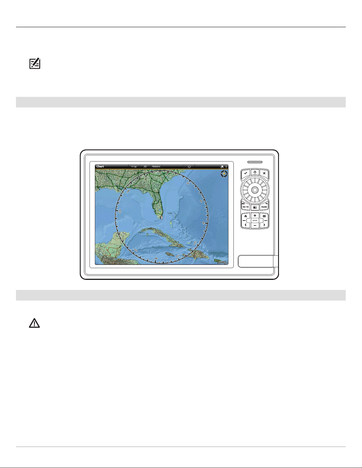
1. Press the HOME key.
2. Review the top, right corner of the status bar.
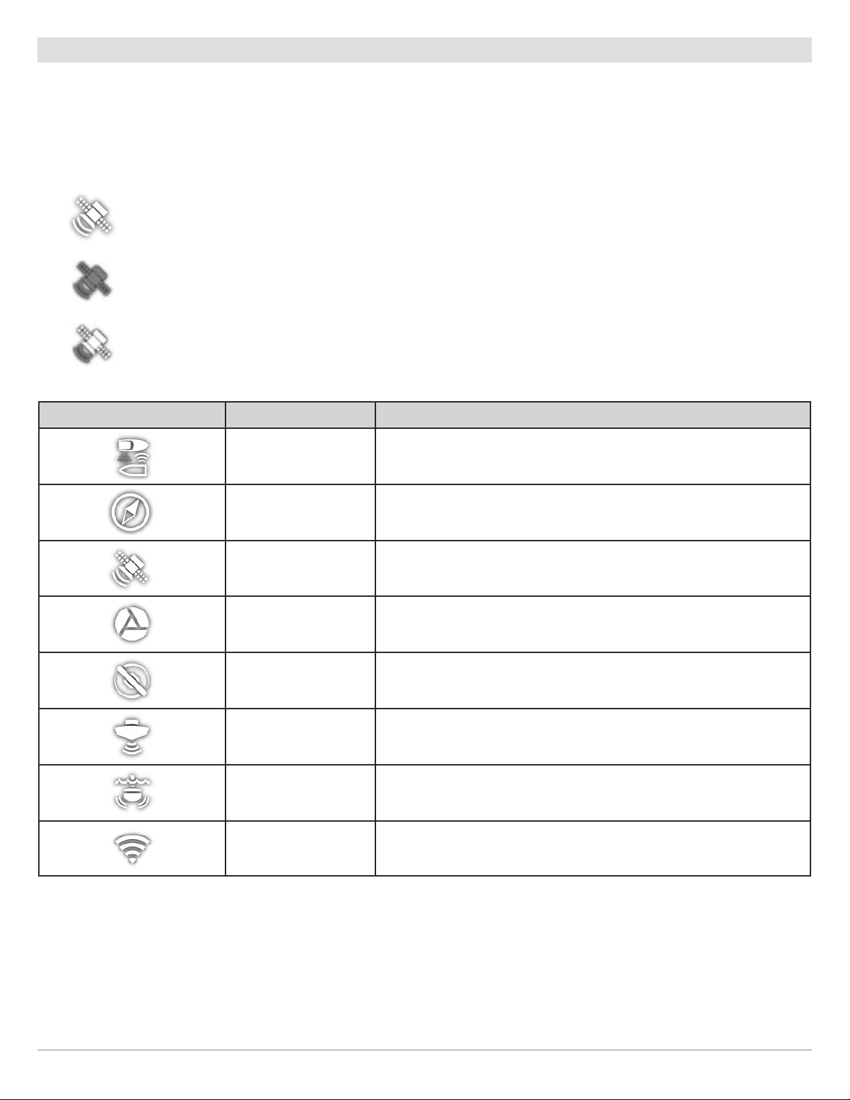
Detected and Active: If a sensor is active and transmitting/receiving, it will be white. See the table below.
Connected but not Detected or Active: If a sensor is not detected on the network, or not transmitting/receiving, it will
be completely gray.
Connected but not Transmitting/Receiving: If a sensor is detected, but is not transmitting/receiving, the icon will be
partially gray. In this illustration, the GPS receiver is detected, but it doesn’t have a GPS fix. This feature will vary with
the type of icon represented.
Active Status Icon Sensor Icon Description
AIS AIS is on and receiving targets.
Compass
GPS The GPS receiver is detected and a GPS fix has been obtained.
i-Pilot Link i-Pilot Link is connected, enabled, and actively navigating.
Radar The selected radar source is detected and transmitting.
2D Sonar The selected 2D sonar source is detected and pinging.
360 Imaging Sonar The 360 Imaging transducer is pinging data.
Wi-Fi Wi-Fi is on and the connection is strong.
The selected compass/heading sensor is on and heading data is being
received.
3. If the sensors are active, your system is ready for use on the water.
For additional system status, select Home > Settings > Network > System Info.
If you have connected an accessory to the control head, and the icon is not displaying in the system status bar, check the
installation of the accessory and the cable connection to the control head.
To change the NMEA 2000 network or multi-control head network sources, see Set up a NMEA 2000 Network and Set up
your Humminbird Network.
Getting Started
8
Page 9
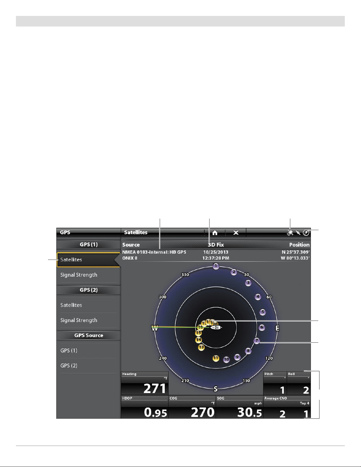
Review GPS Reception
In addition to the sensor icon in the status bar, you can also check the GPS reception status in the GPS tool. The GPS tool provides
two ways to view the satellites communicating with the GPS Receiver. Yellow indicates that the satellite is being used to determine
our current position. Purple indicates that the satellite is being monitored but not used. The following data is also displayed:
y
• Position (latitude and longitude)
• GPS Fix Type: reported as No Fix, 2D Fix, 3D Fix, or Enhanced. An Enhanced fix has been augmented using information from
WAAS, EGNOS, or MSAS. A 3D or Enhanced Fix is required for navigation.
• HDOP (the Horizontal Dilution of Precision): a GPS system parameter which depends on the current satellite configuration.
HDOP is used to calculate the Estimated Position Error.
Open the GPS Tool
If there is more than one control head installed on the network, select the control head that is connected directly to the GPS receiver.
1. Press the HOME key.
2. Select the GPS tool.
Review Satellites and Signal Strength
1. Under GPS (1), select Satellites.
2. Under GPS (1), select Signal Strength.
satellites
communicating
to GPS (1)
GPS (1) Satellite Sky Chart
selected GPS source
fix type
GPS status icon
status bar
used
satellite
(yellow)
monitored
satellite
(purple)
GPS (1) Satellites shows a sky chart and numerical data from the selected GPS receiver
9
digital
readouts
Getting Started
Page 10
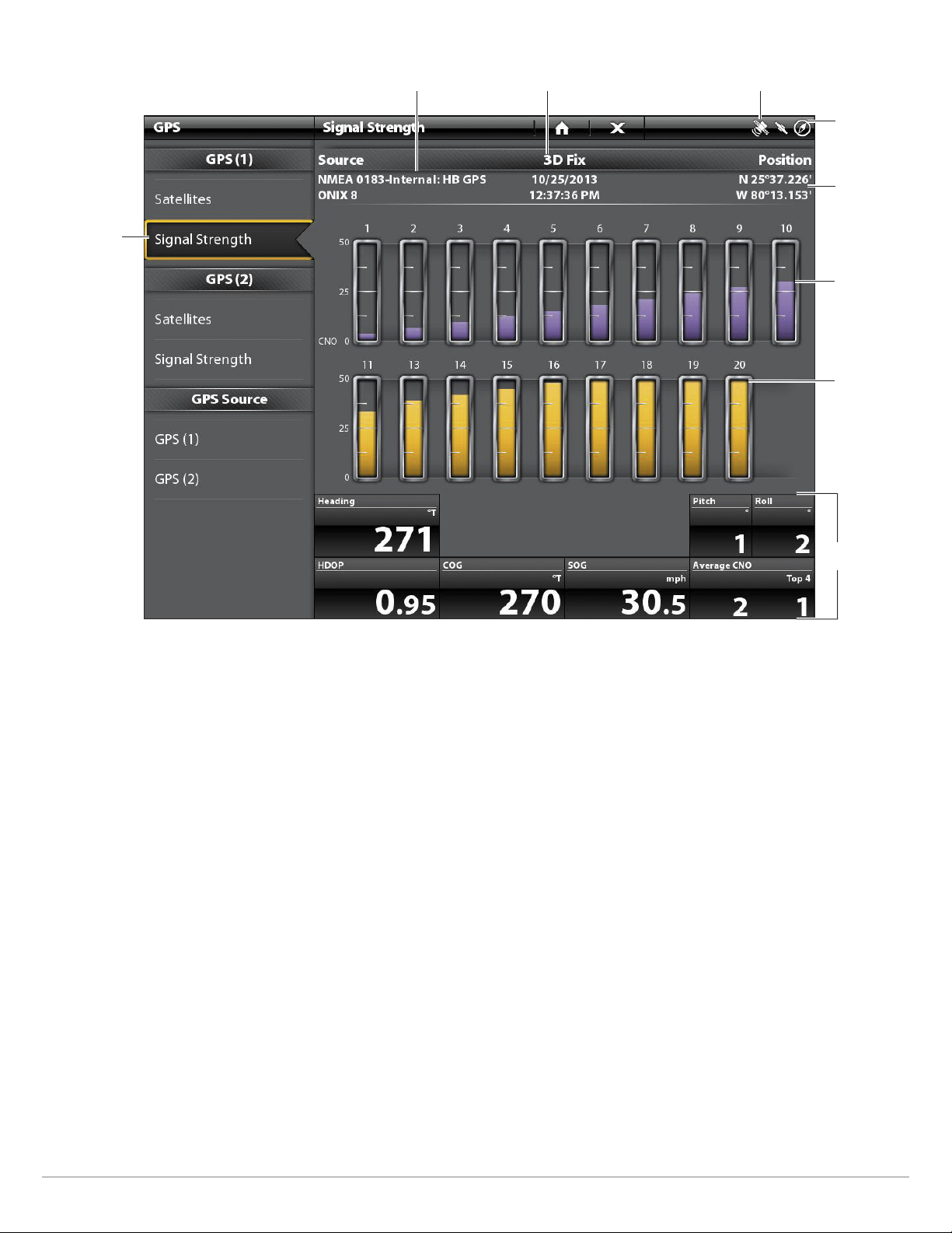
Signal Strength (bar graph)
satellites
signal strength
GPS (1)
selected GPS source
fix type
GPS status icon
status bar
boat position
(latitude/
longitude)
monitored
satellite
(purple) and
strength
level
used satellite
(yellow) and
strength
level
digital
readouts
Signal Strength (GPS 1/GPS 2): displays vertical bar graphs indicating the satellite
signal strengths with the respecting CNO (Carrier-to-Noise) value (0 to 60).
GPS (1) and GPS (2) Sources
You can also manually change which GPS receiver is the selected source for GPS (1) or GPS (2). To change the GPS sources, see
Set up your Humminbird Network.
GPS (1) provides position data, Speed over Ground (SOG), Course over Ground (COG), waypoints, routes, tracks, and navigation
calculations to the control head.
GPS (2) provides position data that is displayed in the GPS (2) data box.
Getting Started
10
Page 11
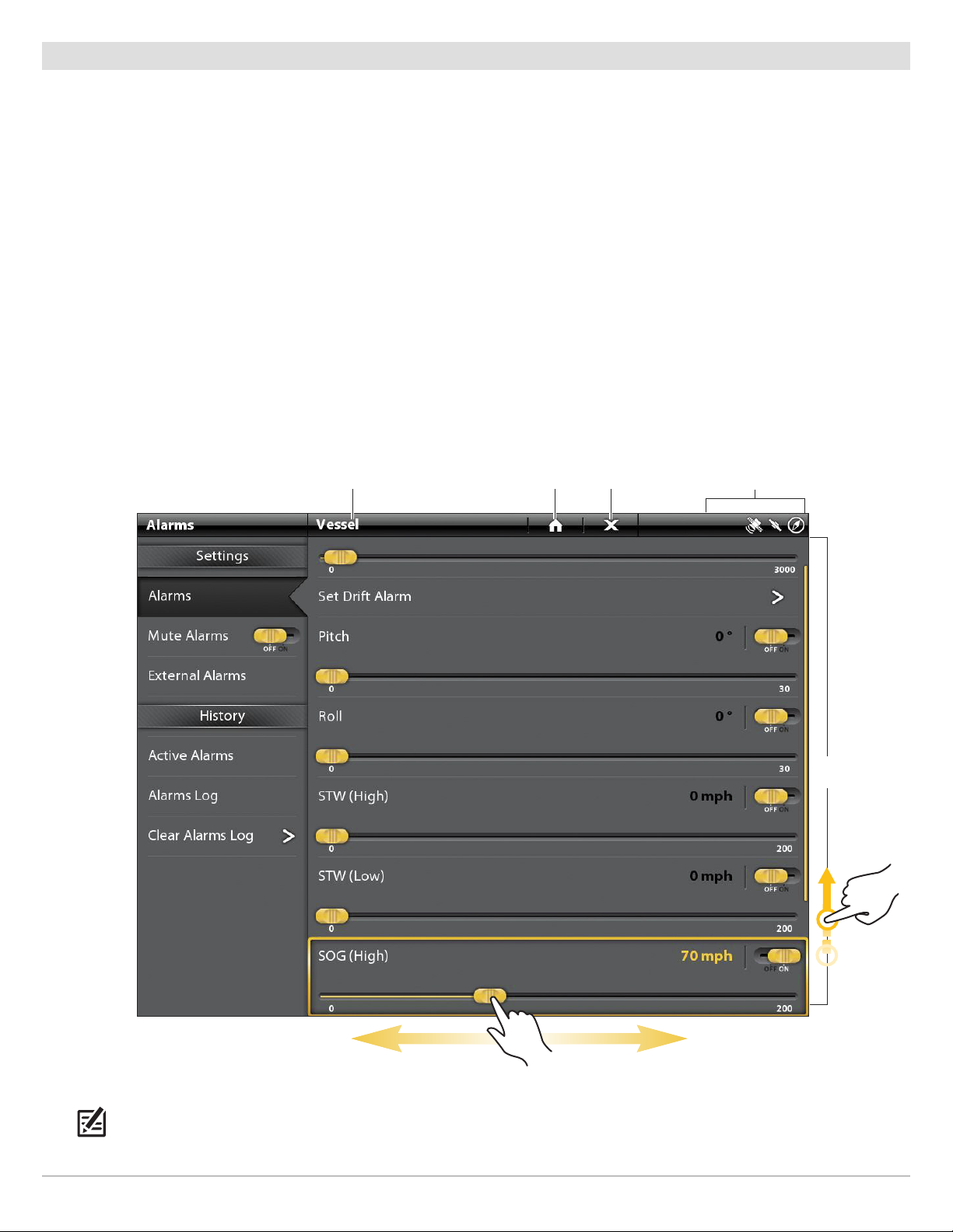
Set Alarms
When an alarm is turned on, an alert will sound or display on the control head to indicate the threshold has been exceeded.
1. Press the HOME key. Select Alarms.
2. Under Settings, select Alarms.
If the control head is connected to the Humminbird network, select Local Alarms (control head only) or Networked Alarms
(alarms shared across control heads). See Set up your Humminbird Network for more information.
3. Select an alarm category.
4. Select an alarm name.
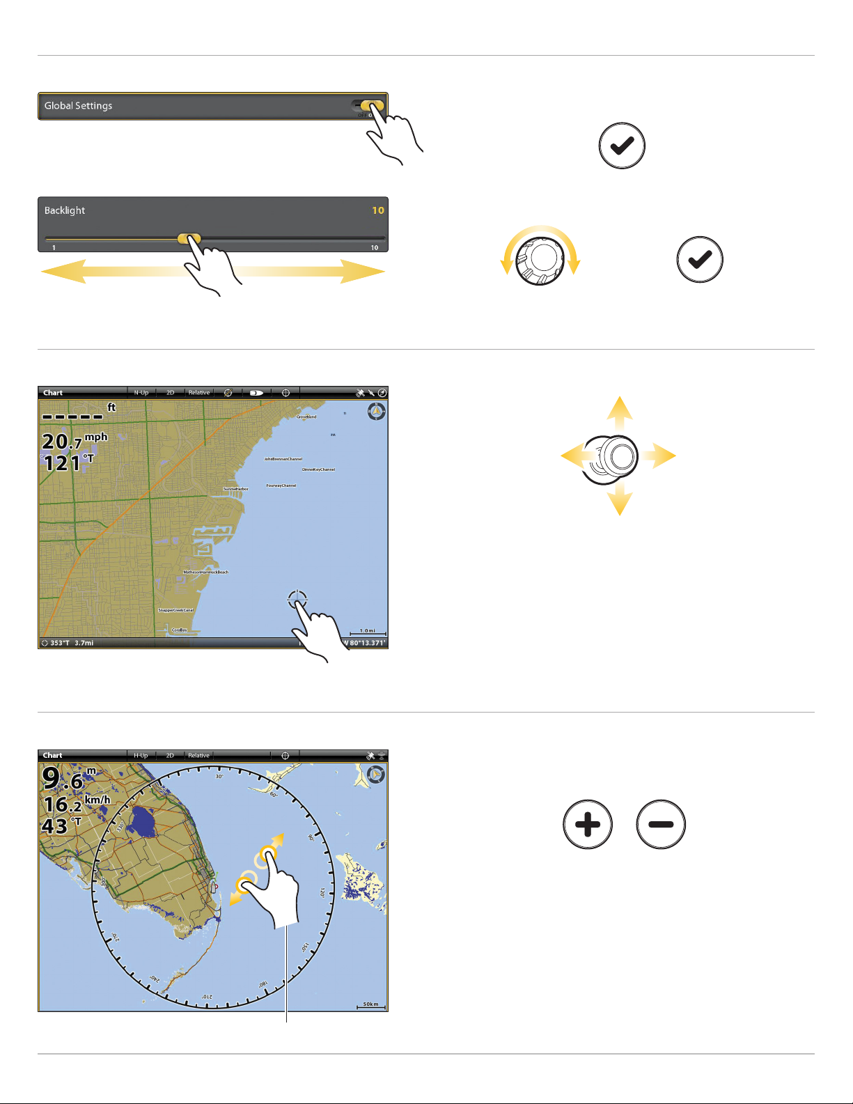
5. On/Off: Tap the on/off button, or press the ENTER key, to turn on the alarm.
6. Adjust the alarm threshold.
Touch Screen: Press and hold the slider, or drag the slider.
Keypad: Press and hold the ENTER key, or turn the Rotary dial.
7. Repeat steps 3 through 6 for each alarm you want to set.
Setting an Alarm (Cross Touch)
selected category home close
status bar
menu
options
NOTE: The touch menus in the status bar are only available in Cross Touch models. See The Menu System: Tips for Using the
Status Bar for details.
11
Getting Started
Page 12
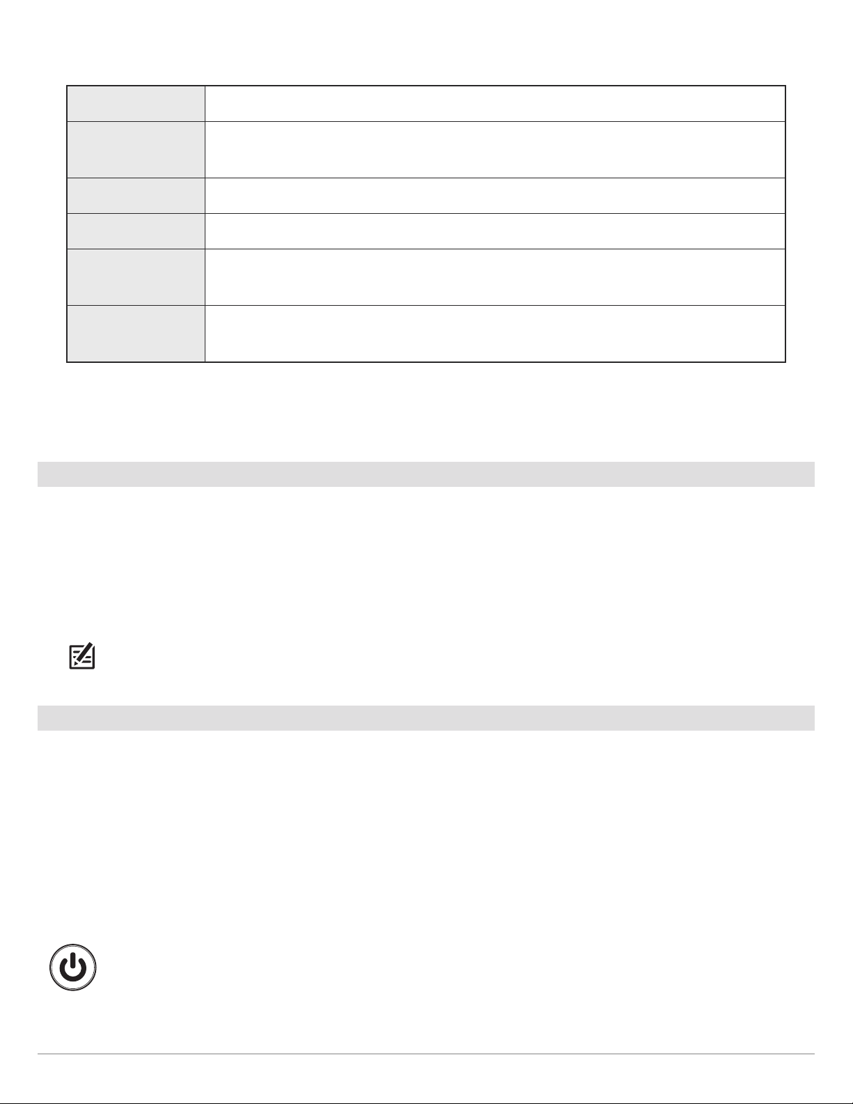
he available alarms are determined by the connected equipment, so your control head may provide more or less options than the
T
nformation shown here.
i
ystem
S
Vessel
Navigation See Chart Overview: Navigation Alarms Overview for details.
Sonar See Sonar Overview: Sonar Alarms for details.
Temperature
Engine
8. External Alarm: If you have connected the Alarm cable (ION only, separate purchase required) to an external klaxon or horn,
select External Alarms. Tap the menu name, or press the ENTER key, to add a check mark to the items that will trigger an
external alert.
oltage, Lost Heading (compass/heading sensor required), etc.
V
Drift Limit, SOG (Speed over Ground), STW (Speed through Water), etc. Also, see Views:
Understand the Data Box Digital Readouts for more information.
Temp (High) or Temp (Low). To change the Temperature sources, see Installation Information:
Set up your Humminbird Network.
Low Fuel, Engine Temp, Oil Level, Coolant Level, Check Engine, etc. To change Engine and Fuel
sources, see Installation Information: Set up a NMEA 2000 Network.
Change System Settings
Your control head was configured during the installation setup. To change the system settings such as the backlight, key sounds,
units of measurement, and the time and date format, select Settings from the Home screen. See Manage your Control Head for
more information.
1. Press the HOME key.
2. Select Settings.
3. Select General.
NOTE: To reconfigure the control head with the Setup Guide, select the Setup Guide tool from the Home screen.
Power Off
Many of the control head settings can be accessed quickly from the Power X-Press Menu. You can also turn off Radar transmission
and Wi-Fi, or change the transducer source from this menu.
Power Off
1. Tap the top, right corner of the status bar.
OR
Press the POWER key.
2. Select Power Off.
Additional Keypad Option
Press and hold the POWER key.
Getting Started
12
Page 13
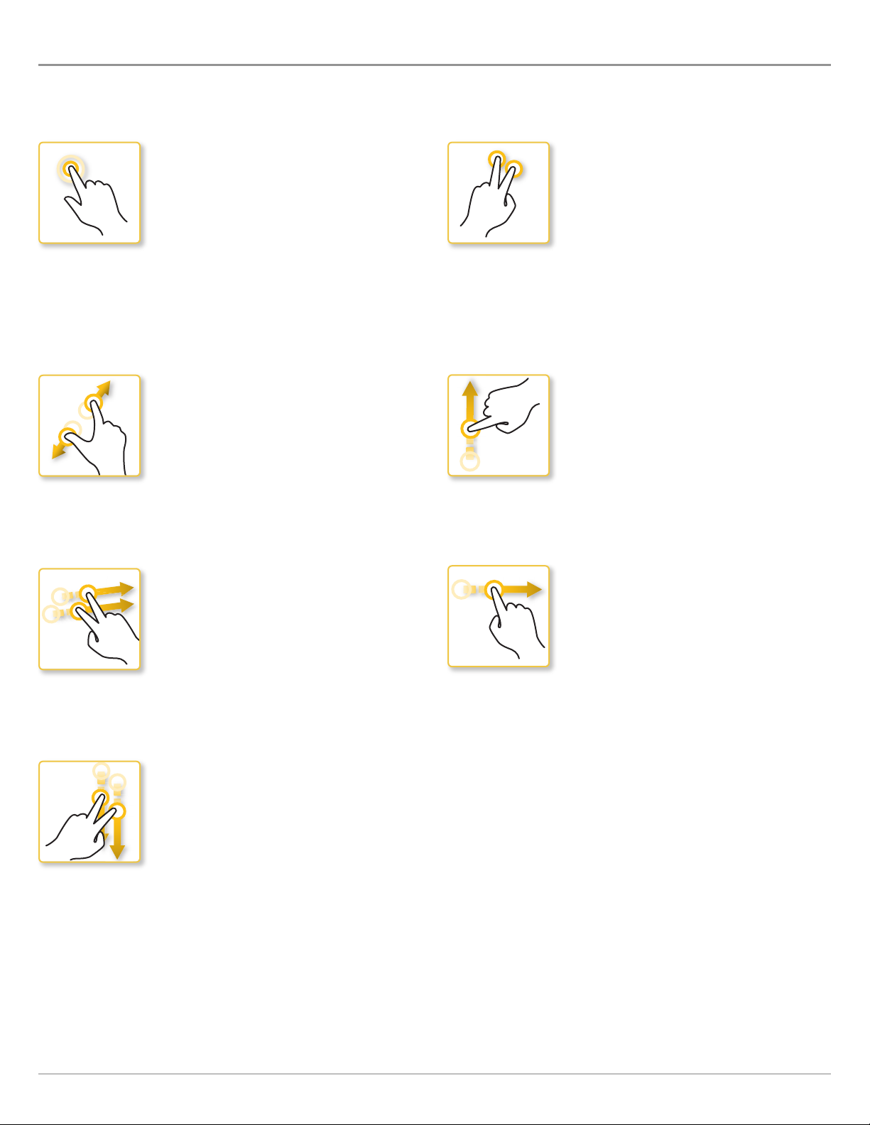
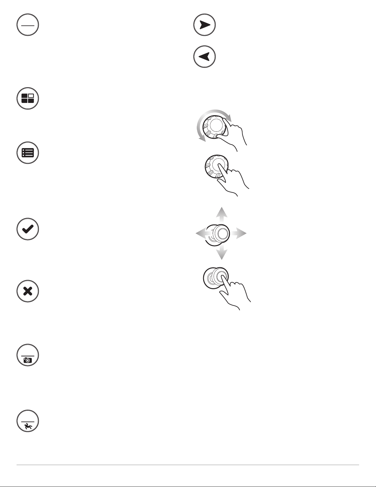
TOUCH SCREEN OVERVIEW (CROSS TOUCH MODELS ONLY)
summary of the touch screen actions are shown here. The touch screen actions are also determined by the view displayed on the
A
creen.
s
TAP OR PRESS AND HOLD
Select a View, Tool, Menu, or Icon: Tap the
selection once.
Activate the Cursor: Tap a position on the
view. Press and hold a position to open the
Cursor menu.
Zoom In: Tap the screen twice.
PINCH IN/OUT
Zoom In: Touch the screen with two fingers
and move them apart.
Zoom Out: Touch the screen with two fingers
and bring them closer together.
TWO FINGER TAP
Switch to 2D or 3D View: With a 2D Chart
View displayed on-screen, tap twice to
switch to 3D or back to 2D (Navionics and
C-MAP by Jeppesen only. See Customize the
Chart View).
Zoom Out: Tap the screen twice.
ONE FINGER SWIPE
UP OR DOWN
Browse Menus: Swipe with one finger to
scroll through a menu list (up or down).
SWIPE SIDE TO SIDE
Next/Previous: With a Favorites View
displayed on-screen, swipe (left or right) to
view the next or previous view available.
SWIPE DOWN
Home Screen/View Toggle: With a view
displayed on-screen, touch the screen with
two fingers and swipe down to go to the
Home Screen. To return to the previous view,
swipe down with two fingers again.
ONE FINGER SWIPE
LEFT OR RIGHT
Adjust Menu Slider: Tap the menu to select
it. Drag the slider to adjust the setting.
See More: Swipe the Favorites View bar and
the Tools bar to browse through the icons on
the Home screen.
Pan: With a Chart View displayed on the
screen, drag one finger across the screen to
see more of the chart that is displayed
off-screen. With a 2D Sonar View displayed
on the screen, drag one finger across the
screen to see more of the sonar history.
13
Touch Screen Overview
Page 14
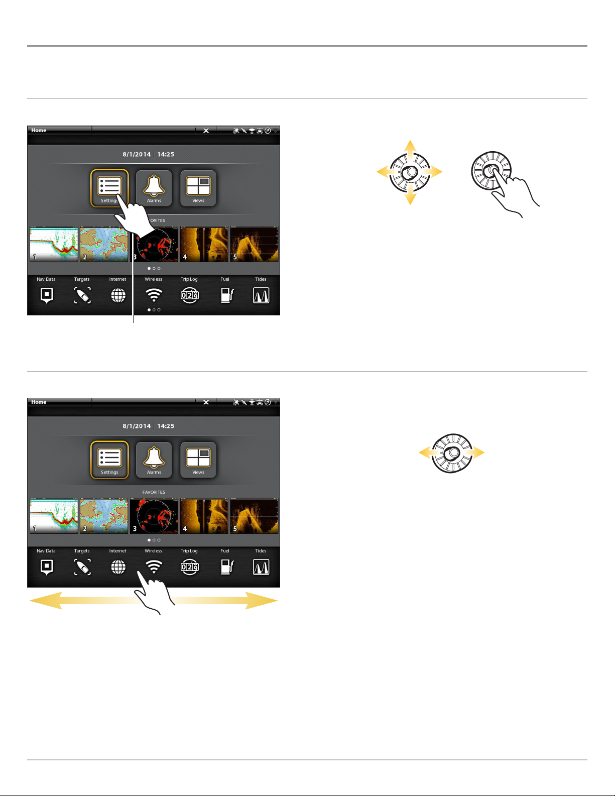
ONIX TOUCH SCREEN AND KEYPAD
ross Touch models allow you to use the touch screen and the keypad to select menus and start actions on the control head. If you
C
ave a Non-Tactile model, you will use the keypad exclusively for all your control head functions.
h
Select a Tool, View, or Menu
Touch Screen Keypad
Select Open
Tap to Select
Scroll to See More
Touch Screen Keypad
Move Left or Right
Swipe Left or Right
ONIX Touch Screen and Keypad
14
Page 15
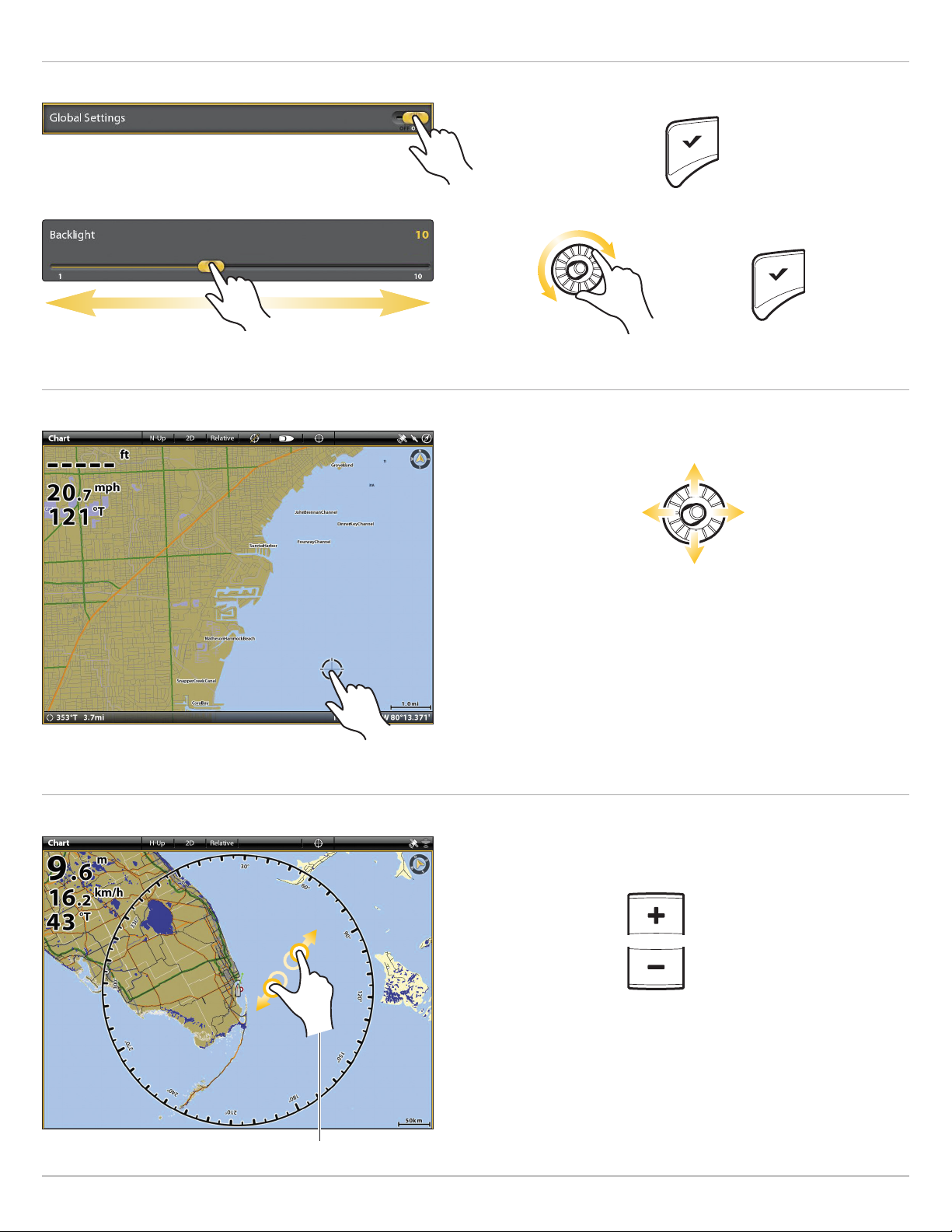
Adjust a Menu Setting
ouch Screen Keypad
T
Tap
Press
OR
Press and Hold OR Slide
Turn
Activate the Cursor
Touch Screen Keypad
Move
Press and Hold
Tap
Zoom In, Zoom Out
Touch Screen Keypad
Pinch In/Out
15
Zoom In
Zoom Out
ONIX Touch Screen and Keypad
Page 16
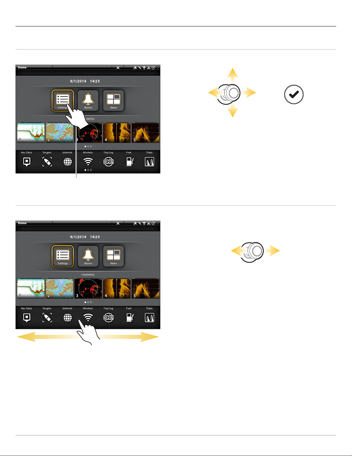
ION TOUCH SCREEN AND KEYPAD
he Cross Touch feature allows you to use the touch screen and the keypad to select menus and start actions on the control head.
T
Select a Tool, View, or Menu
Touch Screen Keypad
Select Open
Tap to Select
Scroll to See More
Touch Screen Keypad
Move Left or Right
Swipe Left or Right
ION Touch Screen and Keypad
16
Page 17
Adjust a Menu Setting
ouch Screen Keypad
T
Tap
Press
OR
Press and Hold OR Slide
Turn
Activate the Cursor
Touch Screen Keypad
Move
Press and Hold
Tap
Zoom In, Zoom Out
Touch Screen Keypad
Zoom In Zoom Out
Pinch In/Out
17
ION Touch Screen and Keypad
Page 18
ONIX CONTROL HEAD
ONIX Key Functions
The functions for each key are described here. To apply the key functions, see each section of this manual. If you have a Cross Touch
model, you can also use the touch screen to replace key functions. See ONIX Touch Screen and Keypad for more information.
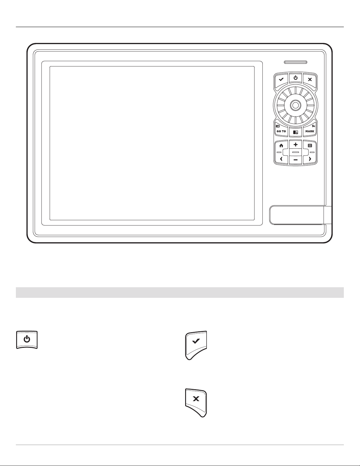
POWER KEY
Press the POWER key to power on the control head.
Press and hold the power key to power off.
During operation, press the POWER key to open a
menu with start-up functions, such as Sonar Source
and Radar Transmit. The menu options depend on the
accessories attached to the system.
ENTER KEY
Press the ENTER key to start a command or turn on a
setting. The ENTER key also opens the Info menu and
the Cursor menu. To adjust a menu setting, press and
hold the ENTER key.
EXIT KEY
The backlight and touch screen can also be adjusted
from this menu.
ONIX Control Head
18
Press the EXIT key once to close a menu, close a
dialog box, turn off an alarm, or exit Cursor mode.
Press and hold the EXIT key to close all menus at
once.
Page 19
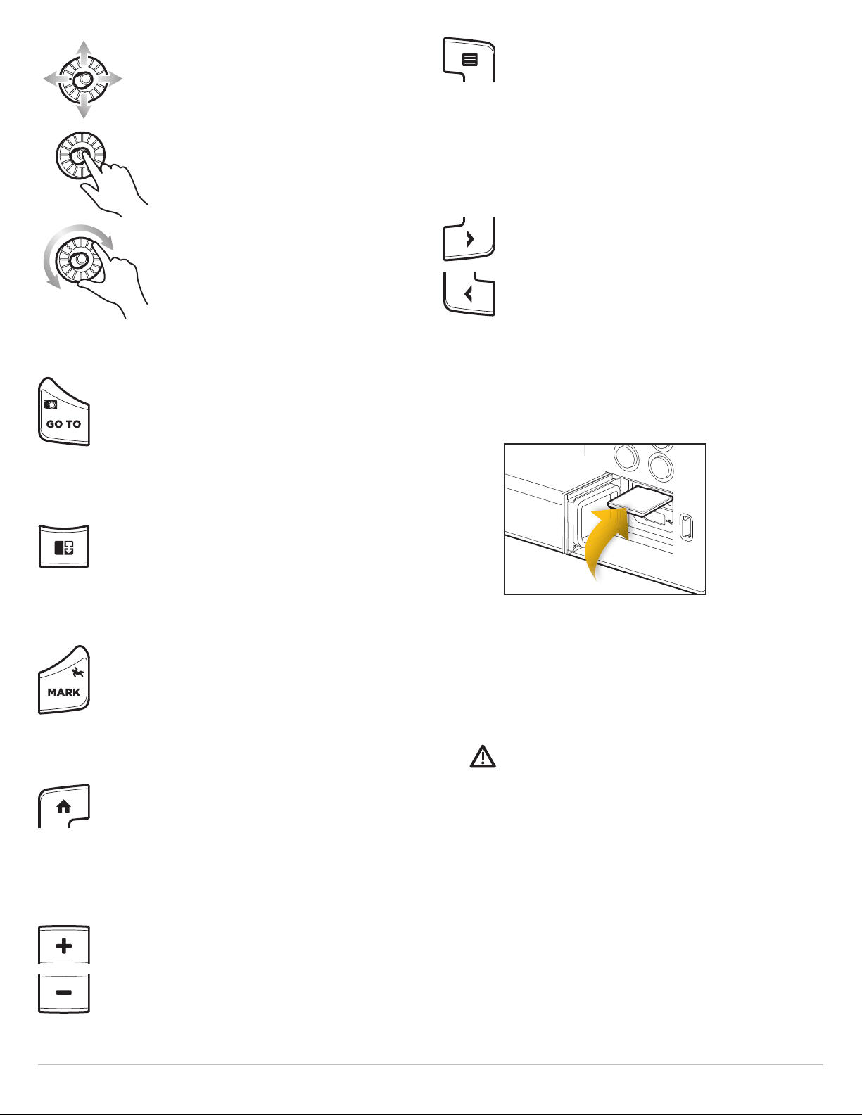
JOYSTICK/ROTARY DIAL
MENU KEY
Move the Joystick to select a view, tool, or
menu. Press the Joystick to open your
selection.
The Joystick is also used to move the
cursor across the view, pan 2D/3D chart
views, and select menu options and dialog
box information.
Press the Joystick to mark a Route Point.
Turn the Rotary dial to adjust menu
settings, or press and hold the Joystick.
Similar to the ENTER key, you can press the
Joystick to enter a menu setting or start a
command.
GO TO/SCREEN SNAPSHOT KEY
Press this key once to open the Go To menu for
navigation functions. See Routes for details.
Press and hold this key to save the screen image. See
Images Tool for details.
To open the X-Press Menu for the on-screen view and
operation mode, press the MENU key once. To open
the Main Menu (Settings tool), press the MENU key
twice. To return to the last-used Settings tool tab,
press and hold the MENU key. See The Menu System
for details.
ARROW KEYS
With a view displayed on-screen, press each arrow key
repeatedly until the Favorites view you want to use is
displayed on the screen. See Views for more
information.
Next View: Press the RIGHT ARROW key.
Previous View: Press the LEFT ARROW key.
SD CARD SLOTS
PANE KEY
Press the PANE key to open the View Options menu or
to select a pane in a multi-pane view. The selected
pane is highlighted in yellow. See Views for details.
MARK/MAN OVERBOARD KEY
Press and hold this key to start Man Overboard
Navigation. To mark waypoints, press this key twice.
See Man Overboard (MOB) and Introduction to
Navigation for details.
HOME KEY
Press the HOME key to display the Home screen. The
Home screen allows you to access Settings, Alarms,
Views, and Tools for the control head. See The Home
Screen for details.
ZOOM IN (+)/ZOOM OUT (–) KEYS
Insert an SD card with the label facing up. SD cards
can be used to load additional charts, import/export
navigation data, save screen snapshots, import/export
menu settings, and more. The top slot is displayed as
SD Card (1) in the menu system, and the bottom slot
is displayed as SD Card (2).
CAUTION! Before the control head software is updated
or restored to system defaults, export your menu
settings, radar settings, and navigation data (see
Update Software).
Press the individual ZOOM keys to change the scale
of the view. For a closer view, press the ZOOM IN (+)
key. For a wider view, press the ZOOM OUT (-) key.
Press and hold the ZOOM OUT (–) key to Zoom out all
the way.
19
ONIX Control Head
Page 20
ION CONTROL HEAD
MARK
GO TO
P
ILOT
STANDBY
ION Key Functions
The functions for each key are described here. To apply the key functions, see each section of this manual. You can also use the touch
screen feature to replace key functions. See ION Touch Screen and Keypad for more information.
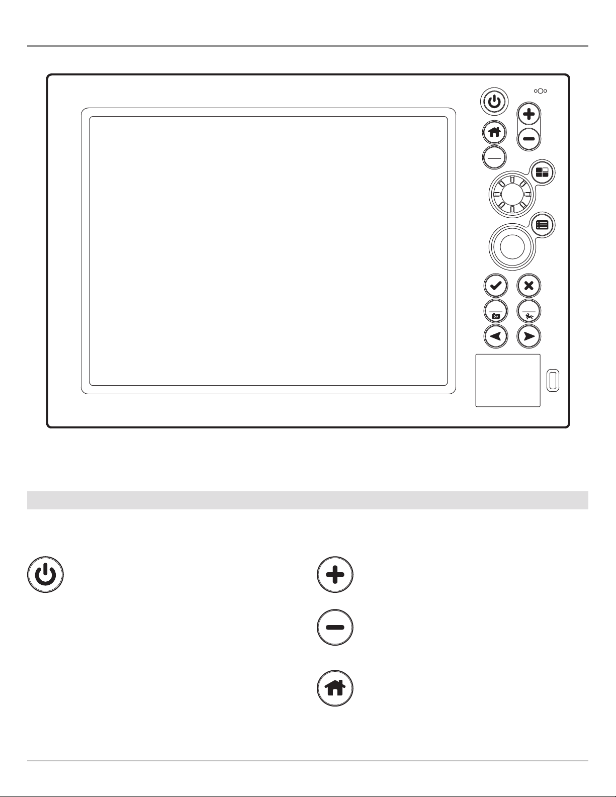
POWER KEY
Press the POWER key to power on the control head.
Press and hold the power key to power off.
During operation, press the POWER key to open a
menu with start-up functions, such as Sonar Source,
Radar Transmit, and Wi-Fi. The menu options depend
on the accessories attached to the system.
The backlight and touch screen can also be adjusted
from this menu.
ION Control Head
20
ZOOM IN (+)/ZOOM OUT (–) KEYS
Press the individual ZOOM keys to change the scale of
the view. For a closer view, press the ZOOM IN (+) key.
For a wider view, press the ZOOM OUT (-) key. Press
and hold the ZOOM OUT (–) key to Zoom out all the
way.
HOME KEY
Press the HOME key to display the Home screen. The
Home screen allows you to access Settings, Alarms,
Views, and Tools for the control head. See The Home
Screen for details.
Page 21
PILOT/STANDBY KEY
MARK
GO TO
PILOT
STANDBY
ARROW KEYS
Use the PILOT/STANDBY key if there is an autopilot
connected to the system. Press the PILOT/STANDBY
key to open the Settings > Navigation menu and turn
on Autopilot Navigation. See Autopilot Overview for
details.
PANE KEY
Press the PANE key to open the View Options menu or
to select a pane in a multi-pane view. The selected
pane is highlighted in yellow. See Views for details.
MENU KEY
To open the X-Press Menu for the on-screen view and
operation mode, press the MENU key once. To open
the Main Menu (Settings tool), press the MENU key
twice. To return to the last-used Settings tool tab,
press and hold the MENU key. See The Menu System
for details.
With a view displayed on-screen, press each arrow
key repeatedly until the Favorites view you want to
use is displayed on the screen. See Views for more
information.
Next View: Press the RIGHT ARROW key.
Previous View: Press the LEFT ARROW key.
ROTARY DIAL
Turn the Rotary dial to adjust menu
settings. Similar to the ENTER key, you
can press the Rotary dial to enter a
menu setting or start a command.
ENTER KEY
Press the ENTER key to start a command or turn on
a setting. The ENTER key also opens the Info menu
and the Cursor menu. To adjust a menu setting, press
and hold the ENTER key.
EXIT KEY
Press the EXIT key once to close a menu, close a
dialog box, turn off an alarm, or exit Cursor mode.
Press and hold the EXIT key to close all menus at
once.
GO TO/SCREEN SNAPSHOT KEY
Press this key once to open the Go To menu for
navigation functions. See Routes for details.
Press and hold this key to save the screen image. See
Images Tool for details.
JOYSTICK
Move the Joystick to select a view, tool,
or menu. Press the Joystick to open your
selection.
The Joystick is also used to move the
cursor across the view, pan 2D/3D chart
views, and select menu options and
dialog box information.
Press the Joystick to mark a Route
Point. Similar to the ENTER key, you can
press the Joystick to enter a menu
setting or start a command. To adjust a
menu setting, press and hold the
Joystick.
MARK/MAN OVERBOARD KEY
Press and hold this key to start Man Overboard
Navigation. To mark waypoints, press this key twice.
See Man Overboard (MOB) and Introduction to
Navigation for details.
21
ION Control Head
Page 22

SD CARD SLOTS AND USB PORT
CAUTION! Before the controlhead software is updated or restored to systemdefaults, export your menu settings,radar settings, and
navigation data (see Update Software).
Load Maps
Insert the SD card with the label facing up
Inserting the USB Stick
SD CARD SLOTS
Insert an SD card with the label facing up. SD cards can be used to load additional charts,
import/export navigation data, save screen snapshots, import/export menu settings, and
more.
The top slot is displayed as SD Card (1) in the menu system, and the bottom slot is displayed
as SD Card (2).
USB PORT
Use the USB port to update software on the control head or import and export navigation data.
Software Updates: For details, see Manage your Control Head.
Import/Export Navigation data: See Manage your Navigation Data.
ION Control Head
22
Page 23
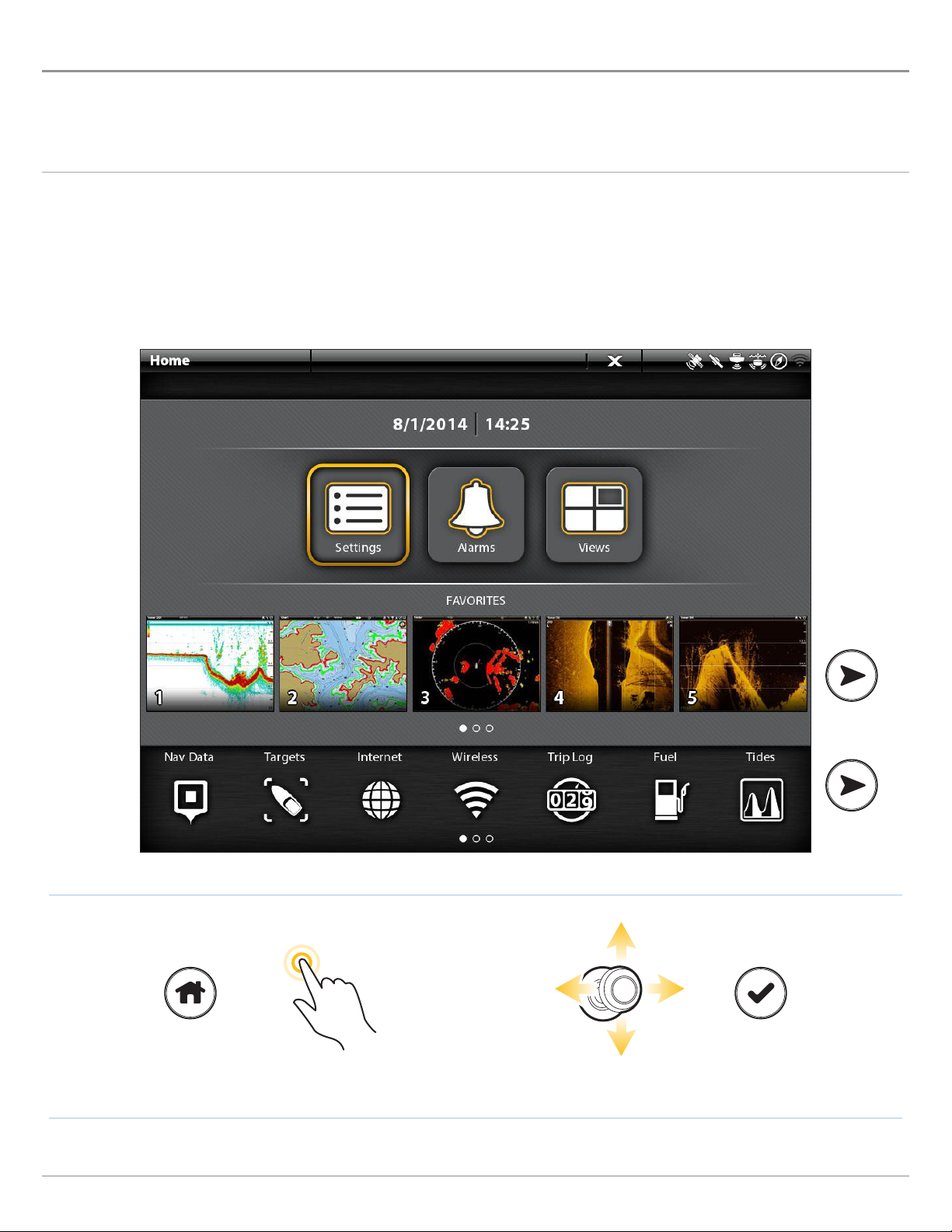
THE HOME SCREEN
he Home screen is the main control center for your control head. Use the Home screen to access the control head settings, alarms,
T
avorite views, and tools. The tools available on the Home screen are determined by the equipment attached to the control head
f
etwork.
n
Open the Home Screen
Touch Screen
1. With a view displayed on-screen, touch the screen with
two fingers and swipe down.
2. Tap a tool or view to open it.
Keypad
1. Press the HOME key.
2. Use the Joystick to select a tool or view. Press the
ENTER key to open it.
OR
Open the Home Screen Tap to Select Select Open
MORE
23
Home Screen
Page 24
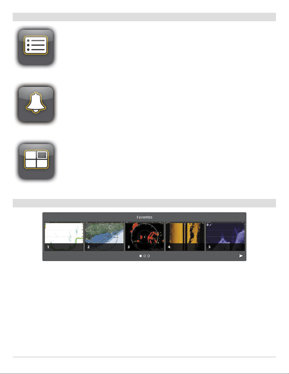
Main Settings
elect Settings to change general system settings such as the backlight, volume, units of measurement,
S
nd the time and date format. You can also use this menu to change the main settings for each application
a
(Sonar, Chart, Radar, etc.). See each related section of this manual for details.
Select Alarms to view the alarm log, turn on external alarms, mute alarm sounds, and set the alarms for
the individual applications. To set up individual alarms for navigation, sonar, radar, AIS, etc., see each related
section of this manual for details. For example, for radar alarm settings, see Radar Alarms.
Select Views to access the complete set of views available on your control head. You can edit views, create
your own views, and save your favorite views. See Views for more information.
Favorites Bar
When you save a view to your Favorites, it is saved to the Favorites bar on the Home screen, so you can open it quickly. See Views
for more information.
Home Screen
24
Page 25
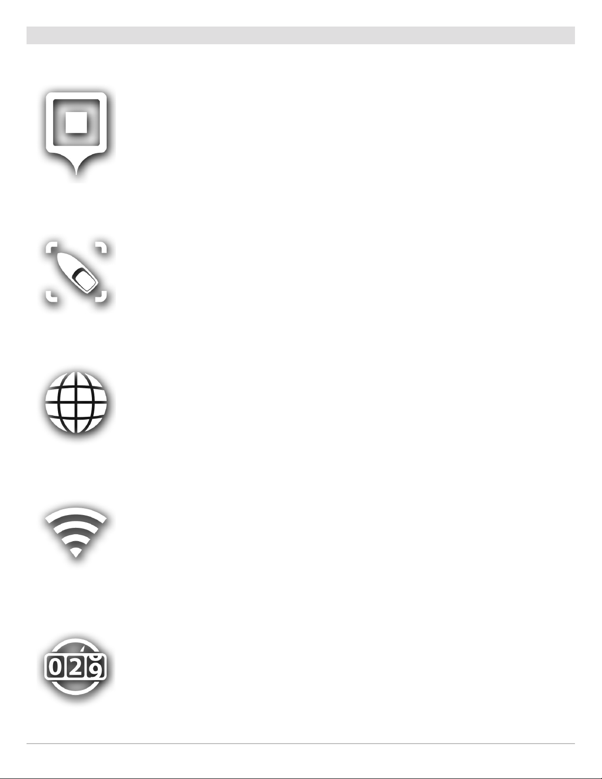
Tools Bar
The Tools bar on the Home screen allows you to manage the control head operations. When you connect an accessory to the control
head, a related tool may also be displayed here.
Select Nav Data to manage your saved waypoints, routes, tracks, and groups. You can create new navigation
data from this screen, edit your saved navigation data, or start navigation (see Manage your Navigation
Data).
Required Equipment: GPS receiver (internal or external)
Select Targets to manage AIS and MARPA targets. See AIS and MARPA for more information.
Required Equipment: AIS or Radar, GPS receiver (internal or external), and compass/heading sensor
Select Internet to open the Browser and surf the Web. See Internet Tool for more information.
Required Equipment: external wireless antenna
This feature is only available on the ION control head.
Select Wireless to connect to wireless networks. This tool allows you to locate wireless networks in the
area and input the required password information. You can also set up a hot spot. See Set up Wireless for
more information.
Required Equipment: external wireless antenna
This feature is only available on the ION control head.
Select Trip Log to display Speed over Ground (SOG), timer for elapsed time, distance traveled since last
reset, average speed, and trip fuel. You can also reset the trip log to zero and review trend data from this
tool.
Required Equipment: GPS receiver (internal or external)
25
Home Screen
Page 26
Select Fuel to review the fuel log for NMEA 2000 fuel sensors connected to the network. This tool provides
refuel alerts and displays the fuel level in graphical form. See Set up a NMEA 2000 Network for details.
Required Equipment: NMEA 2000 tank sensor and/or fuel flow rate sensor
Select Tides to review information for the nearest tide station to your present position. The tool includes
the position of the station and the times of the high and low tides for today’s date. A tide graph is also
displayed showing the rise and fall of the tides for the 24 hour time period encompassing the date. To see
the tide report for the previous day or the next day, press the LEFT or RIGHT ARROW keys. You can also
search data for a selected date.
Required Map Source: Navionics or C-MAP by Jeppesen
Select Currents to review information for the nearest current station to your present position. Two graphs
are also presented that show the time, direction, and flow speed of the current changes for the 24 hour time
period of today’s date. To see the current report for the previous day or the next day, press the LEFT or
RIGHT ARROW keys. You can also search data for a selected date.
Required Map Source: Navionics or C-MAP by Jeppesen
Select Sun + Moon to review the sunrise and sunset for today or the date you select. The Moon data provides
the rise and set of the moon and moon phases.
Select Images to manage your screen snapshots. When a screen snapshot is taken, a waypoint can also
be saved at the current position. You can also choose to save the image on the control head, to an SD card,
or USB port (ION only). Also, screen snapshots and pictures from your camera’s SD card (JPG Files) can be
displayed in a slideshow from this tool. See Images Tool for more information.
Home Screen
Select Recordings to start a sonar recording or select a save location. You can also watch a sonar recording
from the perspective of a 2D, SI, or DI View, depending on the capabilities of your model. See Sonar
Recording for more information.
Required Equipment: transducer, black box sonar
26
Page 27
Select GPS to review the signal strength of the GPS receivers (“sensors”) connected to the system. The tool
shows the satellites in the area, the positions, and the signal strength for each one. You can also designate
a primary and secondary GPS source from this tool. See Getting Started, Installation Information, and Set
up your Humminbird Network.
Required Equipment: GPS receiver (internal or external)
Select Files to update the software for the control head or connected accessories. You can also import
and export navigation data from this tool, and you can import and export menu settings. Radar installation
settings can be managed from this tool, but only authorized radar technicians should use this menu. See
the following sections: Manage your Navigation Data and Manage your Control Head.
Required Equipment: SD card
Select Timer to set an alarm clock for a selected time of day, use the countdown timer, or use the
stopwatch. You can set more than one alarm clock.
Select Manual to open the control head operations guide. Press the arrow keys to scroll through each page.
To skip to a section, tap the bookmark name in the bookmarks panel, or use the Joystick to select it. Press
the EXIT key to select the bar at the top of the screen. To search for a specific term, select the Find field
and use the on-screen keyboard. To change the page size, press the +/– ZOOM keys. Use the Joystick to
move around the page.
Select Setup Guide, and the control head will guide you through the basic configuration settings for your
control head, including units of measurement, language, transducer source, map source, and vessel
settings. See your installation guide for details. To change the settings after setup, select Home > Settings.
27
Home Screen
Page 28
THE MENU SYSTEM
he ONIX and ION provide menu options that change with the application, on-screen view, and the operations mode.
T
Open Settings
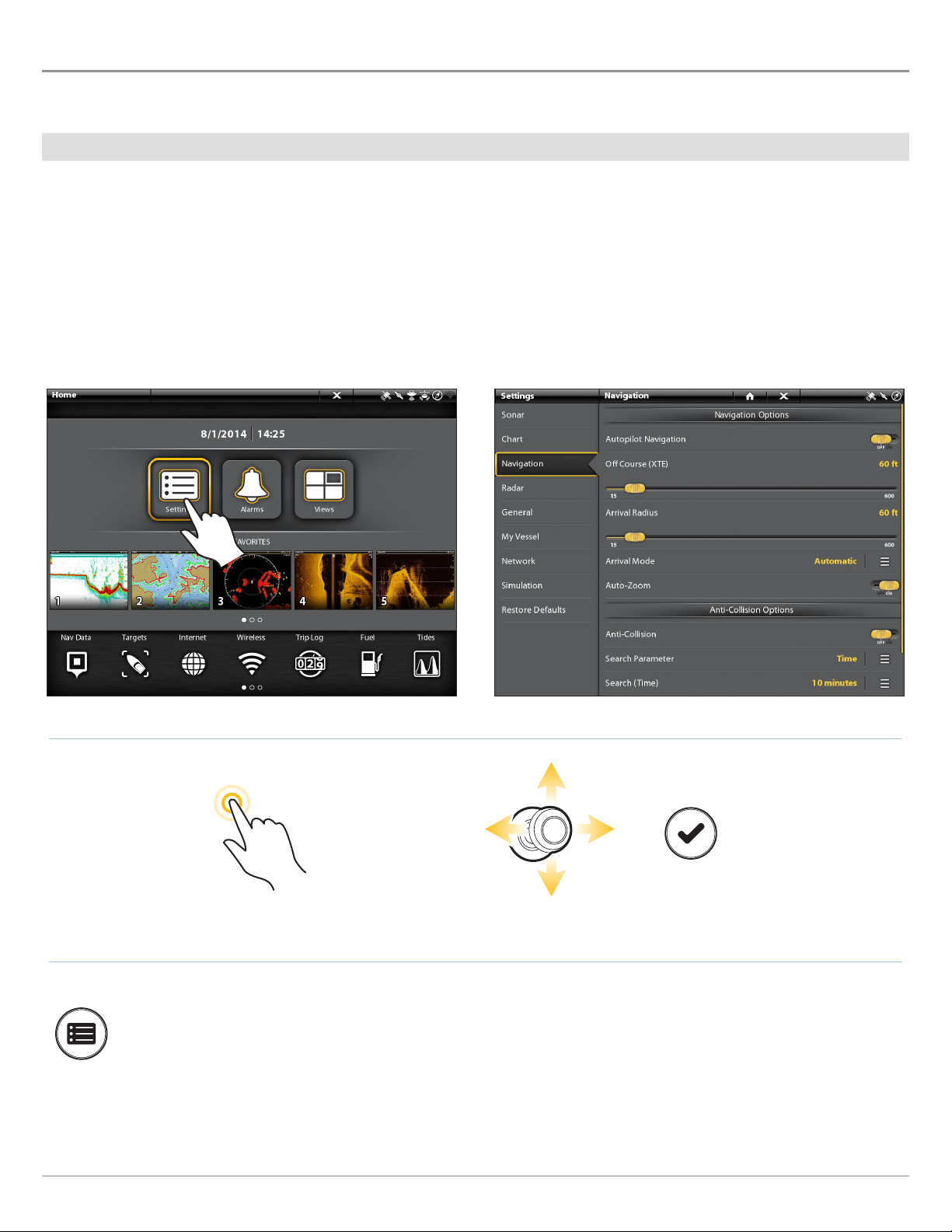
The Settings tool provides main menu settings for the control head.
1. Press the HOME key.
2. Tap Settings.
OR
Use the Joystick to select Settings. Press the ENTER key.
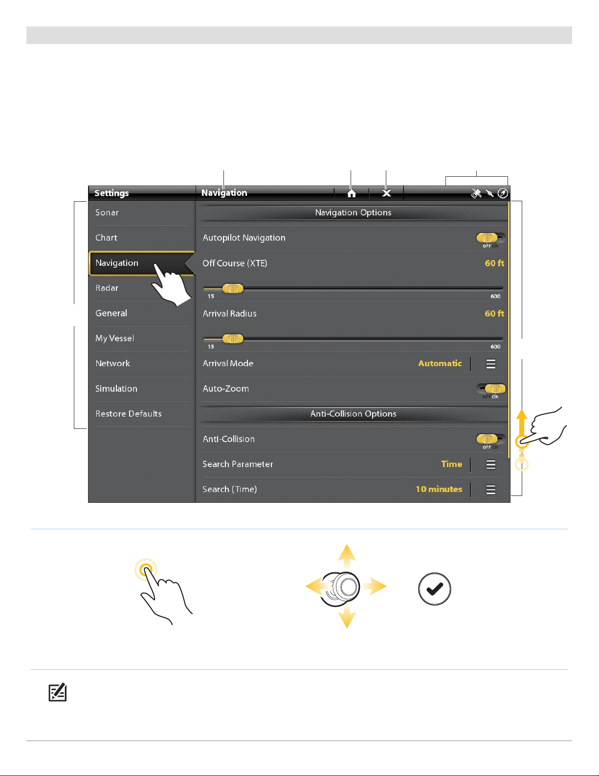
Selecting Settings Navigation Main Menu
Additional Keypad Option
With a view displayed on-screen, press the MENU key twice, or press and hold the MENU key.
The Menu System
OR
Tap Settings Select Settings Open
28
Page 29
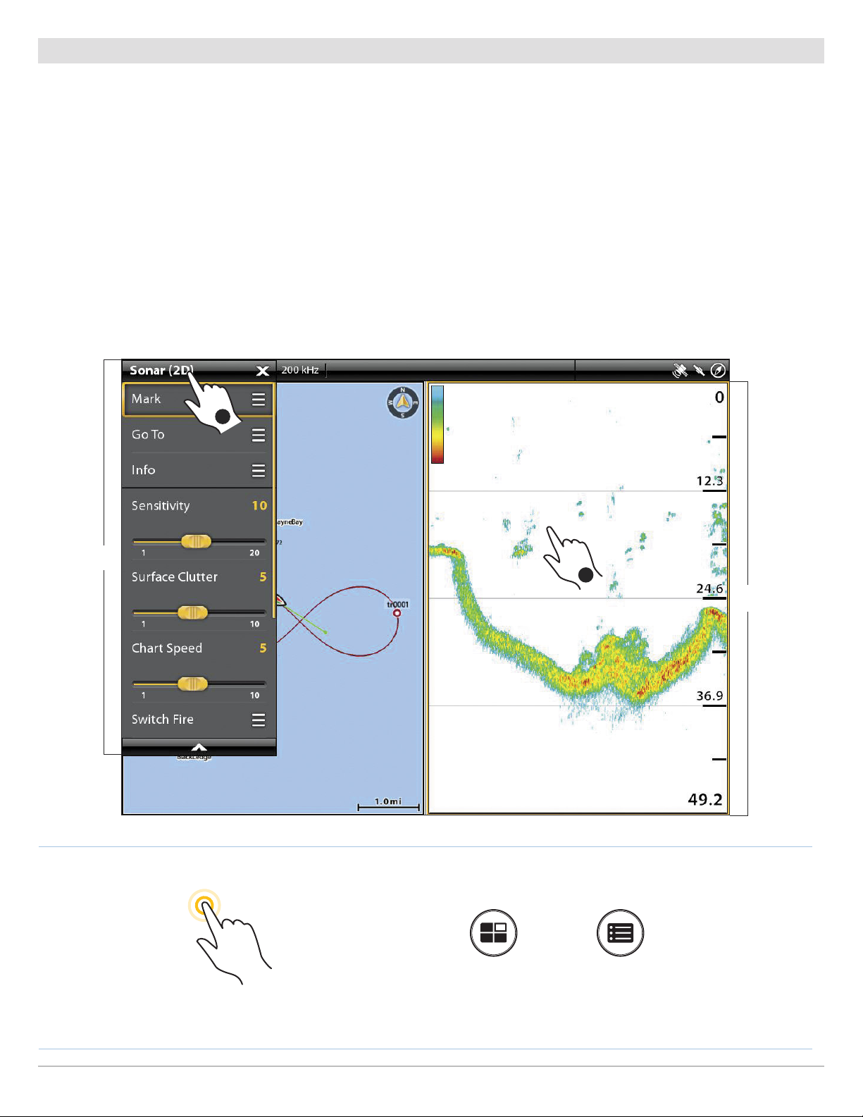
Open an X-Press Menu
The X-Press Menu displays menu options for the on-screen view and operation mode (such as navigation). In a multi-pane view,
the X-Press Menu options are determined by which pane is selected. See Views for more information.
Open an X-Press Menu
1. With a view displayed on-screen, tap the view name in the status bar.
OR
Press the MENU key.
Open an X-Press Menu in a Multi-Pane View
1. With a Multi-Pane View displayed on-screen, tap a pane.
OR
Press the PANE key to select a pane.
2. Tap the view name in the status bar, or press the MENU key.
Opening an X-Press Menu for a Selected Pane
2
X-Press
Menu
1
selected pane
outlined in yellow
OR
Tap to Select a Pane
and the Menu
Press to Select a Pane Press the MENU key
29
The Menu System
Page 30
Change a Menu or Start an Action
Use the following instructions to change a menu setting or start an action through the menu system.
1. Tap a menu category, or use the Joystick to select it.
2. Tap a menu option, or use the Joystick to select it.
3. Adjust the setting or start an action using the touch screen or keys. See Tips for Changing a Menu.
ettings Tool: Navigation Main Menu (Cross Touch)
S
menu
categories
selected category return to Home screen close
status bar
menu
options
NOTE: The touch menus in the status bar are only available in Cross Touch models. See The Menu System: Tips for Using the
Status Bar for details.
The Menu System
OR
Tap to Select Select Open
30
Page 31

Tips for Changing a Menu
This section describes the different types of menus in the menu system and how to change them using the touch screen or keypad.
Action ( > )
Touch Screen Keypad
Tap
Press
On/Off Button
Touch Screen Keypad
Tap
Press
Slider
Touch Screen Keypad
OR
Press and Hold OR Slide
Turn Press and Hold
Pick List or Check Box
Touch Screen Keypad
Press
Tap
You can also use the Joystick to make selections.
31
The Menu System
Page 32

Tips for Using the On-Screen Keyboard
Use the on-screen keyboard to rename the control head in the network, enter an Internet address, edit your navigation data, and
more.
arrows move
the cursor
right or left
uppercase
deletes all text
keyboard language
OR
name field
deletes a single
character
starts a
new line
uppercase
saves changes
space barchanges the
numbers
and symbols
Tap to Select
a Character
Highlight a
Character
Press to Select
the Character
The Menu System
32
Page 33

Tips for Using the Status Bar
The status bar is located at the top of the screen. It changes to match the on-screen view and operation mode.
In the following illustrations, the information in the status bar corresponds with the Chart View displayed on-screen.
tatus Bar (Non-Tactile)
S
displayed information changes to match the on-screen view and status
sensor status
Press the MENU key to open the
X-Press Menu for the on-screen view
Press the POWER key to open
the Power X-Press Menu
In Cross Touch models, you can tap the icon in the status bar to open a menu, return to the Home screen, close a menu, or make
a selection. You can also use the corresponding keys.
Status Bar (Cross Touch)
touch menus change to match the on-screen view and status
Tap to open the X-Press Menu for the on-screen view Tap to open the Power X-Press Menu
sensor status
Close a Menu
When you close a menu, your settings are saved until you change them again or until the control head defaults are restored.
closeback
1. Back: Tap the Back icon to close the current menu and go
back one level in the menu system.
OR
Press the EXIT key.
2. Close: Tap the X icon .
OR
Press the EXIT key. To close several menus at once, press and
hold the EXIT key.
NOTE: The X icon is displayed in the status bar or at the top of a
menu. The location will vary with the item displayed on the
screen.
33
The Menu System
Page 34

VIEWS
he ONIX and ION have many options to display data on-screen, and the data can be displayed in a variety of ways. You can open a
T
iew from the Favorites bar or from the Views tool. You can also create a new view, edit views, and customize the Favorites bar. To
v
dd a view to the Favorites bar, or to remove a view, see Add or Remove the View from the Favorites Bar.
a
Display a View from the Favorites Bar
The Favorites bar includes preset views for your control head. When you attach an accessory to the control head or network, related
views may be added to the Favorites bar. You can also change which views are saved to the Favorites bar.
Display a View
Touch Screen
1. Touch the screen with two fingers and swipe down,
or press the HOME key.
2. Tap a view on the Favorites bar.
Keypad
1. Press the HOME key.
2. Use the Joystick to select a view on the Favorites bar.
Press the ENTER key to display it on-screen.
Display the Next/Previous View
With a view displayed on-screen, you can also go to the next view or previous view in Favorites.
Display the Next/Previous View
Touch Screen
Next View: Swipe the screen with two fingers, right to
left.
Previous View: Swipe the screen with two fingers, left
to right.
Keypad
Next View: Press the RIGHT ARROW key.
Previous View: Press the LEFT ARROW key.
Views
34
Page 35

OR
Tap to Select Select Open
Favorites barFavorites bar
See More:
Swipe or
use the
Joystick
35
Views
Page 36

Display a View from the Views Tool
The Views tool includes the complete database of available views for your control head. Use the Views tool to create a new view and
edit a view. You can also edit the Favorites bar from the Views tool.
1. Press the HOME key.
2. Select the Views tool.
3. Select a Group. To see all available views, select All.
4. Tap the View.
OR
Use the Joystick to select a view. Press the ENTER key to display it on-screen.
Views
OR
Tap to Select Select Open
36
Page 37

groups
Options:
select to create
a new view
Views Tool (Cross Touch)
selected group star = favorite
return to
Home screen
close
status bar
available
views
OR
Tap to Select Select Open
37
Views
Page 38

EDIT THE ON-SCREEN VIEW
ou can edit a view from the Views tool or from the view that is displayed on the screen. When you edit a view from on-screen, the
Y
iew Options menu provides additional editing options.
V
Global: To appy changes to all views in the same category, turn on Global. To apply changes to the on-screen view exclusively,
turn off Global.
The menu options in Data bar, Options, Preferences, and Overlays change to match the on-screen view. The menu
options are described in detail in each section. For example, for Sonar Overlay settings, see Sonar Overview.
Change the View Appearance (Preferences)
Use the Preferences menu to change the appearance of the display. The menu options are determined by the type of view onscreen, and there are many options for each view. For example, in a Sonar View, you can choose the palette, turn on Fish ID+, display
or hide the Real Time Sonar Window, and more.
1. With a View displayed on-screen, tap the view name in the
status bar, or press the MENU key once.
2. Select Options. For example, in a Sonar View, select Sonar
Options. In a Chart View, select Chart Options.
Changing the Sonar View Palette
preview window
3. Select Preferences.
4. Use the touch screen or Joystick to select a menu and change
a setting.
selectionmenu
Change the View Overlays
Use the Overlays menu to display or hide information on the view. For example, in a Chart View, you can display or hide the vessel
icon, and you can choose which navigation data (waypoints, routes, tracks, etc.) you want to display on the view.
Choosing Overlays to Display on a Chart View
1. With a View displayed on-screen, tap the view name in the
status bar, or press the MENU key once.
2. Select Options. For example, in a Sonar View, select Sonar
Options. In a Chart View, select Chart Options.
3. Select Overlays.
4. Use the touch screen or Joystick to select a menu and change
a setting. (check mark = visible, blank = hidden).
Views
38
Page 39

Display Data Overlays
Digital readout data can be displayed as an overlay, and it can be displayed in the data bar. To turn on the data bar, see Display a
Data Bar.
Chart View with Data Overlays Displayed
1. With a View displayed on-screen, tap the view name in the
status bar, or press the MENU key once.
2. Select Options. For example, in a Sonar View, select Sonar
Options. In a Chart View, select Chart Options.
3. Select Overlays.
4. Select Data Overlay.
5. Select Show Data. Tap the on/off button, or press the ENTER
key, to turn it on.
6. Use the touch screen or Joystick to make items visible on the
view. (check mark = visible, blank = hidden).
data overlays
Display a Data Bar
Your control head allows you to choose a standard data bar or a navigation data bar with preset data boxes. If you attach
additional accessories to the control head or network, additional data bar options may also be displayed. The data boxes in the
data bar can also be changed.
Select the Data Bar Type
1. View Options Menu: With a view displayed on-screen, press the
PANE key once. In a multi-pane view, press the PANE key
repeatedly until the menu displays.
2. Select Data Bar from the View Options menu.
3. Select the type of data bar to display. To hide the data bar,
select Off.
NOTE: To display digital readouts as an overlay, see Display Data
Overlays.
39
Views
Page 40

hange the Data Boxes
C
Use the following instructions to change the data boxes displayed in a data bar.
NOTE: A data bar must be displayed to access the menu options in this section. See Display a Data Bar.
1. View Options Menu: With a view displayed on-screen, press the PANE key once. In a multi-pane view, press the PANE key
repeatedly until the menu displays.
2. Select Edit Data.
3. To edit the Standard data bar, select Standard Data. To edit the Navigation data bar, select Navigation Data.
Global (Optional): To apply the changes to all views using the data bar, turn on Global. To apply changes to the on-screen view
exclusively, turn off Global.
4. Use the Joystick to choose a data box. Press the Joystick to select it.
5. Select a data type from the menu.
6. Select a data label.
7. Close: Press the EXIT key. Press the PANE key.
Selecting a Data Box Selecting the Data Type Selecting the Data Label
Views
OR
Tap to Select Select Open
40
Page 41

nderstand Data Box Digital Readouts
U
The table below displays the basic data box options that are shown in the Standard data bar and the Navigation data bar, as well as
the additional data box options for vessel, wind, and engine. The data box options are determined by the installed equipment and the
selected sources on the network. Your control head provides a wide variety of data box options, more than the information shown here.
The number on the data label (Temp 1, Temp 2, Temp 3, etc.) corresponds with the source number. For more information about
sources and networking, see Installation Information, Set up your NMEA 2000 Network, and Set up your Humminbird Network:
Select Data Sources.
Label Name Description Data Type
Alt Altitude The height measurement above sea level. Vessel
AWA Apparent Wind Angle The direction of wind relative to the bow of the vessel. Wind
AWS Apparent Wind Speed The speed of wind with respect to the speed of the vessel. Wind
Brg Bearing
Brg (End) Bearing (To End)
Course Course
CMG Course Made Good
COG Course Over Ground
CTS Course to Steer
Depth (#) Depth
Dest Wpt ID Next Waypoint
DBT Depth Below Transducer
The compass direction from the vessel position to the next waypoint
or route point.
The compass direction from the vessel position to the final point in a
route.
The intended direction of travel measured between the start point and
end point.
The bearing from your starting position to the present vessel position.
The goal is to have CMG and Track equal to the same number.
The current direction the boat is traveling measured in degrees from
North. When the COG is equal to Bearing, the boat is said to be on
course and will arrive at the destination in the most efficient manner.
The heading that must be maintained in order to reach the planned
destination.
The depth of the water from the transducer or digital depth sensor to
the bottom. This measurement includes the depth offset setting.
The next point (waypoint, route point, Man Overboard point, etc.)
that the vessel is navigating towards in a route or other navigation
mode.
The depth of the water below the transducer. This measurement
does not include the depth offset setting.
Navigation
Navigation
Navigation
Navigation
Vessel
Navigation
Depth
Navigation
Depth
DMG Distance Made Good
DTG Distance to Go
Eng Temp (#) Engine Temperature The engine temperature from the engine source. Engine
Eng Volt (1) Engine Voltage The power supplied to the engine source. Engine
ETA
Estimated Time
of Arrival
The straight line distance actually traveled between the start position
to the current vessel position.
The distance between the vessel position and the next waypoint or
route point.
The estimated time of arrival to the next waypoint on the route. Navigation
Navigation
Navigation
41
Views
Page 42

Label Name Description Data Type
Fuel (#) Fuel Level The fuel level of the fuel source. Fuel
The direction the boat is pointing, measured in degrees. Due to wind
Hdg Heading
and waves, the boat is often traveling in a slightly different direction
than its heading. See Course Over Ground (see COG).
Vessel
Heat Index Heat Index
Next Turn Next Turn The course of the next route leg with respect to the current heading. Navigation
Odo Odometer The distance traveled. Vessel
Pitch Pitch The rotation angle of the boat from front to back (bow to stern). Vessel
Position (#) GPS
Roll Roll The rotation angle of the boat from side to side (port to starboard). Vessel
ROT Rate of Turn The rate at which the boat is turning, measured in degrees per second. Vessel
RPM Revolutions Per Minute The number of engine revolutions per minute. Engine
SMG Speed Made Good
The perceived temperature derived from air temperature and relative
humidity.
The latitude and longitude coordinates of the vessel position based
on the GPS receiver installation location.
The distance from the starting waypoint on the route divided by the
time elapsed since starting navigation on the route.
Environment
Vessel
Speed
The measurement of the boat’s progress across a given distance
SOG Speed Over Ground
STW Speed Through Water
Temp (#) Water Temperature The detected water temperature. Environment
Temp (Air) Air Temperature The detected air temperature. Environment
TTG Time to Go
TWA True Wind Angle The wind angle detected when the vessel is stationary. Wind
TWS True Wind Speed The wind speed detected when the vessel is stationary. Wind
VMG Velocity Made Good The speed of travel relative to the next waypoint on the route. Speed
XTE Cross Track Error
and the speed measurement provided by GPS. SOG is optimal for
navigation because accurate destination times can be derived from
this measurement.
The measurement of the flow past the boat, which may vary depending
on current speed and direction.
The estimated time required to reach the next waypoint on the route.
TTG is calculated using the SOG (Speed Over Ground) and DTG (Distance
to Go).
The straight-line distance of the boat from the intended Track. XTE
measures how far the boat is off course.
Speed
Speed
Navigation
Navigation
Views
42
Page 43

THE VIEW OPTIONS MENU
T
O
The menu options vary slightly. For example, if you open the View Options menu from an onscreen view, you can also edit the data bar from the menu. If you open the View Options menu
from the Views tool, you can duplicate and delete the view from the control head.
he View Options menu provides options to edit the selected view. You can open the View
ptions menu from the on-screen view or from the Views tool on the Home screen.
Open the View Options Menu for the On-Screen View
1. With a view displayed on-screen, press the PANE key once. In a
multi-pane view, press the PANE key repeatedly until the menu
displays.
2. Close: Press the PANE key.
Opening the View Options Menu
View Options menu
43
Views
Page 44

Open the View Options Menu from the Views Tool
1. Press the HOME key.
2. Select the Views tool.
3. Press and hold the view you want to edit.
OR
Use the Joystick to select a view. Press the MENU key.
4. Close: Press the EXIT key.
Opening the View Options Menu from the Views Tool (Cross Touch)
selected group return to Home screen close
status bar
Views
View Options Menu
OR
Press and Hold Select
44
Open the View
Options Menu
Page 45

CREATE A NEW VIEW
ollow the instructions in this section to create a new view from a blank template.
F
1. Press the HOME key.
2. Select the Views tool.
3. Select New View.
4. See Edit the View Layout and Application to rename the view, edit the layout, add applications, display digital readouts, and
more.
Creating a New View
select to create a new view
45
Views
Page 46

dit the View Layout and Application
E
The Edit menu on the View Options menu allows you to change the type of data that is displayed in the view and how many panes
are displayed.
1. Select Edit (or Edit View) from the View Options menu.
2. To change the layout and number of panes in the view, select Template. If you do not want to change the layout, skip to step 4.
3. Tap the template, or use the Joystick, to select the layout you want to use.
4. To change the type of data displayed in the view, select Applications.
5. Tap the pane and then tap the type of data to fill the pane.
OR
Turn the Rotary dial to select a pane. Use the Joystick to choose an application, and press the Joystick to select it.
6. Repeat steps 4 and 5 until the panes are filled.
7. Select Save.
Selecting a View Template
template tab
save
preview window
templates
selected template
OR
Views
Tap to Select Select a Template Open
46
Page 47

applications tab
save
Adding Applications to the Template
preview window
selected pane
applications
selected application
OR
Tap to Select Select a Pane Select an Application Add
47
Views
Page 48

hange the View Name (Views Tool)
C
1. Select Name from the View Options menu.
2. Use the on-screen keyboard to edit the view name. See The Menu System: Tips for Using the On-Screen Keyboard for more
information.
Add or Remove the View from the Favorites Bar
1. Select Favorite View from the View Options menu.
2. Tap the menu, or press the ENTER key, to add/remove the check mark. (Check mark = Favorites bar, Blank = not included in
the Favorites bar)
Optional: In the Views tool, tap the star to add/remove the view from the Favorites bar. (Star = Favorites bar, Blank = not
included in the Favorites bar)
Duplicate the Selected View (Views Tool)
When you duplicate a view, the control head creates a copy. You can rename the new view, edit it, and change the layout.
1. Select Duplicate from the View Options menu.
2. Tap the menu, or press the ENTER key, to create a copy.
Delete the Selected View (Views Tool)
1. Select Delete from the View Options menu.
2. Tap the menu, or press the ENTER key, to delete the view.
Views
48
Page 49

SET UP AN INSTRUMENT VIEW
he ONIX and ION control heads provide Instrument Views in a variety of combinations to display on-screen. You can use the standard
T
ashboard Instrument View or Engine Instrument View. You can also customize the gauges, data boxes, and ranges.
D
NOTE: The data boxes and gauges must have input from connected and powered equipment. The Engine Instrument View must
have input from a NMEA 2000 network to provide source data. For more information about sources and networking, see
Installation Information, Set up your NMEA 2000 Network, and Set up your Humminbird Network.
Instrument View: Dashboard
Display an Instrument View
Touch Screen
1. Press the HOME key.
2. Select the Views tool.
3. Under Groups, select Instrument.
4. Tap an Instrument View.
5. Tap Instrument in the status bar.
6. Select Dashboard or Engine.
Keypad
1. Press the HOME key.
2. Select the Views tool.
3. Under Groups, select Instrument.
4. Use the Joystick to choose an Instrument View. Press the
Joystick.
5. Press the MENU key.
6. Select Dashboard or Engine.
49
Instrument View
Page 50

Customize an Instrument View
In an Instrument View, you can customize the gauges, data boxes, and ranges. You can change each item in the same way you
change data boxes in a view. You can also set up warning limits for the selected data range.
NOTE: The available changes and sources are determined by the selected gauge or data box. As you change data, the available
sources are displayed in white, and the unavailable sources are displayed in black.
Touch Screen
1. With an Instrument View displayed on-screen, tap
Instrument in the status bar.
2. Select Edit Instrument.
3. Press and hold a gauge or data box.
4. Tap the check mark in the status bar.
5. Change the Type of Data: Select Data Type. Select a
category and a data type from the menus.
6. Change the Displayed Range: Select Data Limits.
Select a range from the list.
Set the Warning(s) Threshold: Select a warning (if
available), and tap the on/off button to turn it on. Press
and hold the slider to set the warning threshold.
7. Close: Press and hold the EXIT key.
Selecting a Radial Gauge Selecting a Gauge Selecting a Data Box
Keypad
1. With an Instrument View displayed on-screen, press
the MENU key.
2. Select Edit Instrument.
3. Use the Joystick to select a gauge or data box. Press
the ENTER key.
4. Change the Type of Data: Select Data Type. Select a
category and a data type from the menus.
5. Change the Displayed Range: Select Data Limits.
Select a range from the list.
Set the Warning(s) Threshold: Select a warning (if
available), and press the ENTER key to turn it on. Turn
the Rotary dial to set the warning threshold.
6. Close: Press and hold the EXIT key.
Instrument View
OR
Press and Hold Select Open
50
Page 51

CHART OVERVIEW
o enable the navigation features, the control head must have a GPS fix from an internal or external GPS receiver (see Getting
T
tarted to check the sensor reception). Some of these features also require a compass/heading sensor to be connected to the
S
ontrol head.
c
The selected map source also influences the menu system. When you change the map source, the menu options for the Chart
Views change, allowing you to add navigation data, shading, or alarms.
2D Chart View (Humminbird), Cross Touch
X-Press Menu motion mode
orientation menu show cursor
sensor status icons
north
indicator
compass
icon
heading
line
boat icon
51
map scale
Chart Overview
Page 52

MAP SOURCE
he ONIX and ION include built-in charts by Humminbird, Navionics, and C-MAP by Jeppesen. You can also install SD cards with
T
dditional chart information for a particular location (separate purchase required).
a
Humminbird is the default map source, but you can change the map source at any time. When you install an SD card, the control
head automatically chooses the best map to display. If you install more than one SD card, you can choose which map source you
want to use.
Compatible Map Sources: Humminbird LakeMaster, Navionics, and C-MAP by Jeppesen. Visit our Web site at humminbird.com for
compatibility details.
Install an SD Chart Card
Load Maps
Insert the SD card with the label facing up
WARNING! Do not leave the SD slot cover open. The slot cover should always be closed to prevent water damage to the unit.
Install an SD Card
1. Insert the card into the slot with the label facing up.
2. The control head automatically chooses the best chart to display. If more than one type
of SD card is installed, follow the on-screen prompts to select the map source.
Eject an SD Card
1. C-MAP by Jeppesen SD Cards Only: Tap the right corner of the status bar, or press the
POWER key. Select Eject C-MAP Card from the menu.
2. All SD Cards: Press the SD card into the slot and release. Pull the card from the slot.
Chart Overview
52
Page 53

Change the Map Source
When you install an SD card, the map source is changed automatically to match the SD card map source. You can also change the
map source using the Settings tool.
When you change the map source, the menu options for the Chart Views also change, allowing you to add navigation data, shading,
alarms, and more. See each section for details.
1. Press the HOME key.
2. Select Settings.
3. Select Chart.
4. Select a Map Source.
Selecting a Map Source (Cross Touch)
select chart
selected category return to Home screen close
sensor status
map source
options
menu options
are determined
by the selected
map source
OR
Tap to Select Select Confirm
53
Chart Overview
Page 54

Set up Humminbird
When Humminbird is selected as the map source, you can use the system defaults, or you can set the menu settings to your
preference. You can use the built-in Humminbird map, or you can install an SD chart card with additional Humminbird LakeMaster
eatures.
f
1. Select Humminbird as the map source.
2. Set the following menus to your preference:
Humminbird:
Chart Card Info
Select this menu to review the information about the installed Humminbird chart card.
Adjust the setting to change the water level read by the control head. For example, if the lake
is down 5 feet, set the Water Level Offset setting to -5. The displayed numbers on the Contour
Water Level
Offset
Lines will adjust from the Water Level Offset setting, and the water level offset will be
highlighted in brown to extend the land visually on the display.
To apply depth colors, depth highlight range, etc., go to the Chart X-Press Menu > Chart
Options > Preferences > Depth. See Open the Chart Preferences Menu for more information.
NOTE: There are also alarm and display options that are exclusively available for Humminbird LakeMaster charts. See Navigation
Alarms Overview and Customize the Chart View for more information.
Chart Overview
54
Page 55

2D Chart View (Humminbird)
contour line
land
water level offset
(brown) extends
the land visually
55
Chart Overview
Page 56

Set up Navionics
When Navionics is selected as the map source, you can use the system defaults, or you can set the menu settings to your preference.
You can use the built-in map, or you can install an SD chart card with additional features.
1. Select Navionics as the map source.
2. Set the following menus to your preference:
Navionics:
Chart Card Info
Easy View
Dynamic
Tides/Currents
Select this menu to review the information about the installed Navionics chart card.
Turn on Easy View to simplify the Chart View. The icon size and text size increase for easier
viewing.
Turn on Dynamic Tides/Currents to display an icon on the Chart View that indicates the status
of the tides and currents. The provided data is affected by the station’s time zone.
Symbols Select USA or International symbols to display on the Chart View.
Use Map Datum to change the map coordinate system used by the control head to match those
Map Datum
of a paper map. Almost all electronic charts use the WGS84 Map Datum and most likely do not
require a setting change. (Default = WGS84)
Use Chart Offset to move the chart position on-screen and correct a position error in the
Chart Offset
cartography. Turn on Chart Offset, and use the sliders to adjust the latitude/longitude
coordinates. The Chart Offset setting applies to all charts, not just the chart that requires
correction.
Turn on Chart Boundaries to display chart boundaries on the Chart View. The dotted lines of a
Chart Boundaries
chart boundary indicate an area that contains a different map. Use the Joystick to move the
cursor within a chart boundary, and press the +ZOOM key to see a closer view of the chart.
NOTE: There are also alarm and display options that are exclusively available for Navionics charts. See Navigation Alarms
Overview and Customize the Chart View for more information.
Chart Overview
56
Page 57

2D Chart View (Navionics)
dynamic
tides/currents
icon
chart boundary
symbols
57
Chart Overview
Page 58

Set up C-MAP by Jeppesen
When C-MAP by Jeppesen is selected as the map source, you can use the system defaults, or you can set the menu settings to your
preference. You can use the built-in map, or you can install an SD chart card with additional features.
1. Select C-MAP by Jeppesen as the map source.
2. Set the following menus to your preference:
C-MAP:
Chart Card Info
Select this menu to review the information about the installed C-MAP by Jeppesen chart card.
Icons Select the size of the icons displayed on the Chart Views.
Map Text Select the size of the text displayed on the Chart Views.
Select Normal or Inverted to set how the water is shaded on the Chart View. When Normal is
selected, dark = deep water, light = shallow water. When Inverted is selected, light = deep water,
Dynamic Depth
dark = shallow water.
Shading
To display dynamic depth shading on the chart, see Open the Chart Preferences Menu: Select
Map Data. Also, use Zoom to see more or less shades on the view.
Current Arrows Turn on Current Arrows to display the tidal current arrows on the Chart View.
Symbols Select USA or International symbols to display on the Chart View.
Use Map Datum to change the map coordinate system used by the control head to match those
Map Datum
of a paper map. Almost all electronic charts use the WGS84 Map Datum and most likely do not
require a setting change. (Default = WGS84)
Chart Offset
Chart Boundaries
NOTE: There are also alarm and display options that are exclusively available for C-MAP by Jeppesen charts. See Navigation
Alarms Overview and Customize the Chart View for more information.
Chart Overview
Use Chart Offset to move the chart position on-screen to correct a position error in the
cartography. Turn on Chart Offset, and use the sliders to adjust the latitude/longitude
coordinates. The Chart Offset setting applies to all charts, not just the chart that requires
correction.
Turn on Chart Boundaries (Standard) to display chart boundaries on the Chart View. The dotted
lines of a chart boundary indicate an area that contains a different map. Use the Joystick to
move the cursor within a chart boundary, and press the +ZOOM key to see a closer view of the
chart.
Turn on VAD (Value Added Data) to display additional details from the installed SD chart card
(separate purchase required).
58
Page 59

2D Chart View (C-MAP by Jeppesen)
dynamic depth
shading
current arrow
symbols
59
Chart Overview
Page 60

NAVIGATION ALARMS OVERVIEW
hen an alarm is turned on, an alert will sound or display on the control head to indicate the threshold has been exceeded. The
W
ettings in this section describe how to turn on a Navigation alarm, adjust the threshold, and display the limits on the view if they
s
re available. The alarm options are determined by the map source.
a
OTE: To turn on additional alarms that relate to your vessel and navigation, such as Lost Heading, Drift Alarm, Pitch, Roll, and
N
more, select Home > Alarms > System and Home > Alarms > Vessel.
Chart View with Alarm Overlays Displayed (Humminbird)
off course
(XTE) limits
displayed in
purple
waypoint
waypoint
avoidance
radius
Navigation Alarms
60
Page 61

Off Course (XTE) Alarm
Turn on Off Course (XTE) to receive an alert if the vessel has traveled outside the selected route. You can also set how far the vessel
is allowed to move off course before the alarm is triggered. If the alarm is turned off, the Off Course limit can be displayed on the
hart View, but you won’t receive an alert if the vessel crosses it.
C
Turn on the Alarm
1. Press the HOME key.
2. Select Alarms > Navigation.
3. Select Off Course (XTE). Tap the on/off button, or press the ENTER key, to turn it on.
Adjust the Parameters (optional)
1. Press the HOME key.
2. Select Settings > Navigation > Off Course (XTE).
3. Press and hold the slider, or press and hold the ENTER key, to set the amount the vessel can move off course.
Display the Off Course (XTE) Limit (optional)
1. With a Chart View displayed on-screen, tap Chart in the status bar, or press the MENU key.
2. Select Chart Options > Overlays > Nav Data.
3. Select XTE Limits.
4. Tap the check box, or press the ENTER key, to add a check mark and make it visible on the view.
Arrival Alarm
Turn on Arrival to receive an alert when the vessel has reached the destination waypoint, route point, or track point. You can also
set the Arrival Radius to indicate how close to the destination point the alarm is triggered. If this alarm is turned off, the Arrival Radius
will be displayed on the Chart View, but you won’t receive an alert if the vessel crosses it.
The Arrival Radius also influences navigation. If the Arrival Radius is set to 60 feet from the destination point, the arrival is
accomplished at 60 feet from the destination point. If there is another point in the route, navigation will then start to the next point.
Turn on the Alarm
1. Press the HOME key.
2. Select Alarms > Navigation.
3. Select Arrival. Tap the on/off button, or press the ENTER key, to turn it on.
Adjust the Parameters (optional)
1. Press the HOME key.
2. Select Settings > Navigation > Arrival Radius.
3. Press and hold the slider, or press and hold the ENTER key, to adjust the radius.
61
Navigation Alarms
Page 62

Waypoint Avoidance Alarm
Turn on Waypoint Avoidance to receive an alert if the vessel has crossed the Waypoint Avoidance Radius. If the alarm is turned off,
the Waypoint Avoidance Radius can be set for a waypoint, and it will be displayed on the Chart View, but you won’t receive an alert
f the radius is crossed.
i
Turn on the Alarm
1. Press the HOME key.
2. Select Alarms > Navigation.
3. Select Waypoint Avoidance. Tap the on/off button, or press the ENTER key, to turn it on.
Create an Avoidance Waypoint
1. See Waypoints: Set the Waypoint Radius and Avoidance to identify a waypoint for avoidance.
Anti-Collision Alarm
If Navionics is selected, and the Anti-Collision alarm is turned on, an alert will be provided based on potential dangers detected in
the chart data ahead of the vessel, such as land, rocks, and restricted areas. You can also select Anti-Collision Objects and how far
in front of the vessel the area will be scanned based on distance or time.
NOTE: Navionics must be selected as the map source to enable this feature.
anti-collision
scan area (gray)
Turn on Anti-Collision
1. Press the HOME key.
Chart View with Anti-Collision Overlay Turned On (Navionics)
2. Select Settings > Navigation.
3. Select Anti-Collision. Tap the on/off button, or press the ENTER key, to turn it on.
Use the Anti-Collision default settings, or use the menus in this section to set how the area is searched (Search Parameters,
Search (Time) or Search (Distance), and Anti-Collision Objects).
Navigation Alarms
62
Page 63

urn on the Alarm
T
1. Press the HOME key.
2. Select Alarms > Navigation.
3. Select Anti-Collision Alarm. Tap the on/off button, or press the ENTER key, to turn it on.
Display the Anti-Collision Overlay
When the overlay is turned off, the scan area is shown only when a danger is detected.
When the overlay is turned on, the scan area is displayed at all times. When a potential danger is detected, the scan area will turn
red.
1. With a Chart View displayed on-screen, tap Chart in the status bar, or press the MENU key.
2. Select Chart Options > Overlays > Vessel.
3. Select Anti-Collision.
4. Tap the check box, or press the ENTER key, to add a check mark and make it visible on the view.
63
Navigation Alarms
Page 64

Guardian Alarm
If C-MAP by Jeppesen is selected, and the Guardian Alarm is turned on, an alert will be provided based on potential dangers detected
in the chart data ahead of the vessel, such as submerged obstructions, land, rocks, and more (Guardian Objects). You can also
elect Guardian Objects and how far in front of the vessel the area will be scanned based on distance or time.
s
NOTE: C-MAP by Jeppesen must be selected as the map source to enable this feature.
hart View with Guardian Area Overlay Turned On (C-MAP by Jeppesen)
C
potential danger
detected
guardian scan area
(purple)
Turn on Guardian
1. Press the HOME key.
2. Select Settings > Navigation.
3. Select Guardian. Tap the on/off button, or press the ENTER key, to turn it on.
Use the Guardian Options default settings, or use the menus in this section to set how the area is searched (Search
Parameter, Search [Time] or Search [Distance], and Guardian Objects).
Turn on the Alarm
1. Press the HOME key.
2. Select Alarms > Navigation.
3. Select Guardian Alarm. Tap the on/off button, or press the ENTER key, to turn it on.
Display the Guardian Area Overlay
When the overlay is turned off, the scan area is shown only when a danger is detected.
When the overlay is turned on, the scan area is displayed at all times. The scan area is displayed in yellow on the chart. When a
potential danger is detected, the scan area will turn red.
1. With a Chart View displayed on-screen, tap Chart in the status bar, or press the MENU key.
2. Select Chart Options > Overlays > Vessel.
3. Select Guardian Area.
4. Tap the check box, or press the ENTER key, to add a check mark and make it visible on the view.
Navigation Alarms
64
Page 65

MAN OVERBOARD (MOB)
MARK
s soon as you know that you have a man overboard (MOB), you should activate Man Overboard navigation to maximize the chances
A
or a successful rescue. Man Overboard navigation marks the approximate point where the person went overboard and starts
f
ontinuous navigation toward the Man Overboard waypoint.
c
Activate Man Overboard Navigation
1. Press and hold the MARK/Man Overboard key.
an Overboard Navigation
M
Man Overboard
navigation in
progress
Man Overboard
waypoint
Man Overboard
data bar
Man Overboard
waypoint position
Elapsed time since the MOB
waypoint was marked
Distance to Go and Time
to Go to the MOB waypoint
When Man Overboard is activated, any current navigation will be canceled and the current route will be discarded without
notification. Man Overboard navigation will begin immediately, and you will see the following on the screen:
Chart View: The view will switch to Chart View automatically.
Man Overboard Waypoint: A waypoint is created at the vessel’s current position, regardless of whether the chart cursor is
active or not.
Continuous Navigation: The control head will begin continuous navigation toward the Man Overboard waypoint.
Auto Zoom: The screen magnifies to show the Man Overboard waypoint and the vessel on the screen.
Data Bar:The data bar will display digital readouts for Man Overboard, including the Man Overboard Waypoint latitude/longitude
position, the elapsed time since Man Overboard was activated, and the Distance to Go and Time to Go to the MOB waypoint
(DTG + TTG ).
Cancel Man Overboard Navigation
1. Press and hold the MARK/Man Overboard key. Select Cancel Navigation.
OR
Press the GO TO key. Select Cancel Navigation.
65
Man Overboard (MOB)
Page 66

CUSTOMIZE THE CHART VIEW
he settings in this section are optional. You can use the default settings for the chart appearance and map source, or you can
T
ustomize the Chart View for your navigation preferences. See Views for more information.
c
OPEN THE CHART PREFERENCES MENU
The Preferences menu allows you to set the chart orientation, motion mode, and vessel offset. For more information about view
preferences, see Views.
1. With a Chart View displayed on-screen, tap Chart in the status bar, or press the MENU key once.
2. Select Chart Options.
3. Select Preferences.
Adjust the Depth Range and Colors
NOTE: Humminbird must be selected as the map source to enable this feature.
1. From the Preferences menu, select Depth.
depth colors
contour interval
depth highlight
Depth Colors Turn on Depth Colors and adjust the range for depth shading in the Chart Views.
Depth Highlight
Highlight Range
Turn on Depth Highlight to highlight a depth setting in the Chart Views. The depth you set will be
highlighted in green. Use Depth Highlight with Highlight Range.
When a Depth Highlight is active in the Chart Views, use Highlight Range to highlight a range on each
side of the highlighted depth. For example, if you know a certain fish is holding at 18 to 20 feet, you
can set the Depth Highlight at 19 feet, and the Highlight Range a +/– 1 foot. The view will show a green
band from 18 to 20 feet.
Shallow Water
Contour Interval
Chart Options
Turn on Shallow Water and adjust the slider. When the depth is equal to or less than the amount set,
it will be highlighted in red in the Chart Views. For example, if your boat has a draft of 3 feet, set the
Shallow Water menu to 3 feet, and the unit will draw a red band from 0 to 3 feet.
Turn on Contour Interval to display lines at set intervals on the Chart View. Adjust the slider to set the
distance between each line. Contour Interval is also affected by the Water Level Offset setting. See
Map Source: Set up Humminbird.
66
Page 67

Set the Chart Orientation
Use the Preferences menu to change the chart orientation. You can also select the Chart Orientation Menu on the status bar.
1. From the Preferences menu, select Orientation.
2. Select an orientation to apply to the chart.
chart orientation setting
preview window
menu
selection
Head Up
(compass or GPS required)
North Up
COG Up
Course Up
Chart Orientation
The vessel’s current heading points up, and the chart rotates around the vessel icon so that
it always points up on the view. The heading is provided by the connected compass/heading
sensor. If a compass is not connected, the vessel will be oriented according to the COG
(Course Over Ground).
The chart is oriented with North up on the display, and the vessel rotates according to its
heading or COG (Course Over Ground).
The chart is displayed with the vessel oriented in a fixed position pointing up, and the chart
rotates according to the vessel COG (Course over Ground).
During navigation, the intended course or route leg is shown at the top of the view. Objects
ahead of the vessel are drawn above the vessel. When the vessel is not navigating, the
current heading is displayed.
Press and hold the slider, or press and hold the ENTER key, to rotate the chart angle. The
chart angle you set will point up on the view.
67
Chart Options
Page 68

Set the Motion Mode
Motion Mode controls how the chart moves on the view.
1. From the Preferences menu, select Motion Mode.
2. Select Relative or True.
Relative The position of the vessel is fixed on the view and the chart moves with the vessel.
True The chart is fixed and the vessel moves towards chart objects on the view.
Turn on/off Vessel Offset
Vessel Offset allows you to see more of the view based on the speed of the vessel. Vessel Offset works with Auto Shift Speed.
1. From the Preferences menu, select Vessel Offset.
2. Select Off, On, or Auto.
Off The vessel is displayed in the center of the Chart View.
On The vessel is displayed on the lower part of the Chart View.
When the vessel is moving below the Auto Shift Speed setting, the vessel icon will be displayed
Auto
3. Close: Press the EXIT key until the menu is closed.
4. To change the Auto Shift Speed Setting, press the MENU key twice. Select My Vessel > Auto Shift Speed.
in the center of the view. When the vessel is moving at or above the Auto Shift Speed setting,
the vessel icon will move to the edge of the view so that more of the view is shown on-screen.
Turn on Auto Zoom
Auto Zoom focuses the view on the current route leg as it is being navigated. As the vessel’s speed increases, the chart range will
increase. If you press the ZOOM keys to see more or less of the view, Auto Zoom will pause.
NOTE: The Auto Zoom setting does not apply to the 3D Views.
1. Press the HOME key.
2. Select Settings.
3. Select Navigation.
4. Select Auto-Zoom. Tap the on/off button, or press the ENTER key, to turn it on.
Chart Options
68
Page 69

Select Map Data
When a Navionics chart or C-MAP by Jeppesen chart is installed and selected as the map source, you can set navaids, marine, and
land icons to hidden or visible. The Depth menu option allows you to see shading on the map based on the set depth.
NOTE: C-MAP by Jeppesen or Navionics must be selected as the map source to enable this feature. The menu options will change
with the selected map source.
1. With a Chart View displayed on-screen, tap Chart in the status bar, or press the MENU key once.
2. Select Chart Options.
3. Select Map Data.
4. Use the touch screen or the Joystick to select a menu and change the settings.
Chart View with Navaids and Icons Displayed (Navionics)
69
Chart Options
Page 70

CHANGE THE CHART VIEW OVERLAYS
se the Overlays menu to display or hide information on the view. In a Chart View, you can display or hide the vessel icon, navigation
U
ata (waypoints, routes, tracks), data overlays, AIS and MARPA targets, and range rings. The available menu options are determined
d
y the accessories attached to the control head network. Also, see Views for more information about Overlays.
b
1. With a Chart View displayed on-screen, tap Chart in the status bar, or press the MENU key once.
2. Select Chart Options.
3. Select Overlays.
4. Use the touch screen or Joystick to select a menu and change a setting. (check mark = visible, blank = hidden).
Chart View with Overlays Displayed (Humminbird)
north
indicator
compass icon
waypoint
route point
saved route
track
heading line
boat icon
map scale
Chart Options
70
Page 71

CHART AND RADAR
f a radar is connected to the control head network, the radar data can be displayed on the Chart View. To adjust the menu settings
I
or the radar, see Radar Overview for more information.
f
Display Radar on the Chart View
1. Start Radar Transmission: Press the POWER key once. Select Radar Transmit, and turn it on.
2. With a Chart View displayed on-screen, tap Chart in the status bar, or press the MENU key once.
3. Select Radar.
4. Select Radar Overlay. Tap the on/off button, or press the ENTER key, to turn it on.
NOTE: You can also display Range Rings and MARPA Targets on the Chart View. See Change the Chart View Overlays in this section
for more information.
Turning on the Radar Overlay (Cross Touch)
status bar
radar menu
71
Chart Options
Page 72

CHANGE THE CHART MODE
se the instructions in this section to switch the Chart View from 2D to 3D. C-MAP by Jeppesen also allows you to choose
U
erspective.
P
NOTE: C-MAP by Jeppesen or Navionics must be selected as the map source to enable this feature.
Change the Chart Mode
Touch Screen
1. With two fingers, tap the screen twice.
OR
1. Tap Chart in the status bar.
2. Select Chart Mode.
3. Select a menu option.
NOTE: In Cross Touch models, menu options are also available in the status bar. See the illustration Switching to Perspective
Mode.
Keypad
1. Press the MENU key.
2. Select Chart Mode.
3. Select a menu option.
Chart Mode
72
Page 73

Switching to Perspective Mode (C-MAP by Jeppesen), Cross Touch
The display options can be accessed from
the status bar or the Chart X-Press Menu.
Tap Twice
OR
Press the MENU key Select Chart Mode
73
Chart Mode
Page 74

INTRODUCTION TO NAVIGATION
our Humminbird control head allows you to mark waypoints, create a route, and start navigating. Waypoints, routes, and tracks can
Y
e managed on-screen so you can save your favorites, edit names, and easily return to your favorite destinations.
b
There are many ways to start navigation or edit navigation data with your Humminbird control head. The instructions in this section
review navigation features on the Chart View. To use navigation features from the Nav Data tool, see Manage your Navigation Data.
NOTE: To start navigation from your control head to your autopilot, see the autopilot section of this manual.
Chart View with Waypoints, Routes, Tracks (Cross Touch)
waypoint
route point
saved route
X-Press Menu motion mode
chart orientation show cursor
status bar
Introduction to Navigation
Tap to Activate the Cursor
track
OR
Move the Joystick to
Activate the Cursor
74
Page 75

NAVIGATION MENU OVERVIEW
hether you have a Cross Touch Model or a Non-Tactile keypad control only model, there are many ways to use the navigation
W
eatures on your control head. The Navigation X-Press Menu and Cursor menu are opened using the touch screen. The same menus
f
re also opened by pressing the MARK key, GO TO key, or ENTER key.
a
This section is an overview of the menus available for navigation. The availability of menu options is determined by the
navigation mode and your Humminbird model. To apply these functions, see Waypoints, Routes, Tracks, and Search.
Navigation X-Press Menu (Cross Touch Models Only)
The Navigation X-Press Menu allows you to open the following navigation menus: Mark, Go To, and Info. The Navigation X-Press Menu is only available in Cross Touch models with the Chart View, Sonar Views, or Radar View displayed on-screen with Navigation enabled.
Open the Navigation X-Press Menu
1. With a Chart View displayed on-screen, tap Chart in the status bar.
2. Select Mark, Go To, or Info.
3. Select an action from the submenu. For example, to mark a waypoint, select Mark > Waypoint.
Navigation
X-Press
Menu
Using the Touch Screen to Open the Navigation X-Press Menu (Cross Touch)
close
75
Introduction to Navigation
Page 76

Mark Menu
The Mark menu marks a waypoint at the selected location. You can also create a saved route
or mark the vessel position. See Waypoints and Routes for more information about using this
enu.
m
Open the Mark Menu
1. Touch Screen: Select Mark from the Navigation X-Press Menu.
OR
Keypad: Press the MARK key.
Mark Menu Options
Waypoint
Route Select Route to create a saved route. See Routes for more information.
Lat/Long Use the on-screen keyboard to manually enter a latitude/longitude position for a waypoint.
Vessel Position
(with activecursor)
Select Waypoint to save a waypoint at the vessel position. If the cursor is active, the waypoint
is saved at the cursor position.
Select Vessel Position to save a waypoint at the vessel position even though the cursor is
active.
Go To Menu
The Go To menu starts navigation to the item you select. See Routes for more information about
using this menu.
Open the Go To Menu
1. Touch Screen: Select Go To from the Navigation X-Press Menu.
Introduction to Navigation
OR
Keypad: Press the GO TO key.
76
Page 77

Go To Menu Options
Quick Route
Nav Data Open the Nav Data tool to select saved navigaton data and start navigation.
Lat/Long
Go To Cursor If the cursor is active, navigation will start to the cursor position.
When the Go To menu is opened during navigation, additional menu options are available, including the following:
Cancel
Navigation
Select Quick Route to mark quick route points and start navigation. See Routes for more
information.
Open the on-screen keyboard to enter a latitude/longitude position. Select Go To to start
navigation to the position.
Go To Menu Options (during navigation)
Select Cancel Navigation to cancel navigation with the control head.
Select Restart Course to start navigation from the current vessel position instead of from the
Restart Course
Next Point Select Next Point to skip the current point and navigate to the next route point in the route.
Reverse Route
first route point. The control head will recalculate navigation to the next closest point in the
route. This is helpful if the boat has navigated off course from the current route.
Select Reverse Route to reverse the currently navigated route. Navigation will start from the
vessel position and continue in the opposite order.
77
Introduction to Navigation
Page 78

Info Menu
Use the Info menu to start a proximity search. You can also set a trolling grid from this menu.
If you are using Humminbird as the map source, you can search lake information. Navionics
and C-MAP by Jeppesen also have additional search options.
If you have Radar and AIS attached, use this menu to search targets (See Radar Overview, AIS
and MARPA).
Open the Info Menu
1. Touch Screen: Select Info from the Navigation X-Press Menu.
OR
Keypad: Press the ENTER key.
NOTE: If you select a waypoint, route, or track with the cursor, and then press the ENTER key,
the Info menu for the selected item will display.
Introduction to Navigation
78
Page 79

Info
Ruler
Info Menu Options
Select Info to search the area within a preset range for a variety of data, including
cautions, tide stations, current stations, and ports. The available information is
determined by the selected map source and the information available in the search
area. See Search for more information. (Navionics and C-MAP by Jeppesen only)
Select Ruler to measure the distance between two positions on the view. Press the
ENTER key to select the measurement start point. Move the Joystick to the second
selected position, and press the ENTER key to mark the measurement end point.
Lake List
Lake Name
Find Nearest
Trolling Grid
AIS: All Inactive Select this menu to change all tracked AIS targets to inactive (see AIS and MARPA).
AIS List
MARPA: All Inactive Select this menu to cancel all MARPA targets (see AIS and MARPA).
Select Lake List to search for lakes within a preset range. Humminbird must be selected
as the map source. See Search for more information.
Select Lake Name to open the on-screen keyboard and search for a lake by name.
Humminbird must be selected as the map source. See Search for more information.
Select Find Nearest to search the closest waypoints, routes, and tracks within a preset
range. See Search for more information.
Select Trolling Grid to apply a trolling grid to a position on the Chart View. See Waypoints
for more information.
Select this menu to display a list of all AIS targets within the AIS transmission range (see
AIS and MARPA).
MARPA List Select this menu to display a list of all MARPA targets (see AIS and MARPA).
79
Introduction to Navigation
Page 80

Cursor Menu (Cross Touch Models Only)
The Cursor menu is another way to use the touch sceen and mark a waypoint, create a route, or start a search. The Cursor menu is
only available in Cross Touch models with the 2D Chart View, Sonar Views, or Radar View displayed on-screen.
Open the Cursor Menu
1. Press and hold a position on the Chart View.
Displaying the Cursor Menu (Cross Touch)
show vessel show cursor
cursor menu
cursor
Introduction to Navigation
Press and Hold
80
Page 81

WAYPOINTS
aypoints are saved latitude/longitude positions. They mark a position of interest such as your favorite fishing area,
W
tructure, or marker buoy. The control head saves the position and allows you to edit the waypoint name, icon, and more
s
see Manage your Navigation Data). You can save 5,000 waypoints to the control head.
(
Mark Waypoints
Waypoints can be marked at the vessel position or cursor position. To edit the waypoint, see Edit a Waypoint in the Chart View or
Manage your Navigation Data. To display waypoints on the chart as they are marked, see Change the Chart View Overlays.
Mark a Waypoint at the Vessel Position
Touch Screen
1. Tap Chart in the status bar.
2. Select Mark.
3. Select Waypoint.
Mark a Waypoint at the Cursor Position
Touch Screen
1. Press and hold a position on the Chart View.
2. Select Waypoint.
Keypad
1. Press the MARK key twice.
Keypad
1. Use the Joystick to move the cursor to a position on
the chart.
2. Press the MARK key twice.
81
Waypoints
Page 82

MARK
Marking a Waypoint at the Cursor Position
The Mark menu opens when you press the MARK key
or select Mark from the Navigation X-Press Menu.
cursor
Waypoints
Press and Hold
OR
to Activate the Cursor
82
Move the Joystick
Press the
MARK key Twice
Page 83

ark + Edit Waypoints (on the go)
M
If you set the Mark Mode to Mark + Edit, you can edit a waypoint immediately when you mark it in the Chart View. See Manage your
Navigation Data for more information.
1. Press the HOME key.
2. Select the Nav Data tool.
3. Under Options, select Waypoints.
4. Select Mark Mode > Mark + Edit.
5. Close the Nav Data tool and display a Chart View on-screen.
When you mark a waypoint, the Waypoint Info menu will be displayed so you can edit the waypoint.
Mark Favorite Waypoints (on the go)
If you set the Mark Mode to Mark Favorites, you can edit a waypoint immediately using your Favorites settings. The waypoints will
be saved to the group you designate. See Manage your Navigation Data for more information.
1. Press the HOME key.
2. Select the Nav Data tool.
3. Under Options, select Waypoints.
4. Select Mark Mode > Mark Favorites.
5. Select the Back icon to return to the previous menu, or press the EXIT key.
6. Select Favorite Settings, and set your favorite icons, colors, group, etc.
7. Close the Nav Data tool and display a Chart View on-screen.
When you mark a waypoint, the Favorites menus will be displayed so you can edit the waypoint using the options you set in
Favorite Settings.
Move a Waypoint in the Chart View
1. Use the Joystick to move the cursor to a waypoint on the chart.
2. Press the ENTER key.
3. Select Move.
4. The menu will close. Use the Joystick to move the waypoint to a new position.
5. Press the ENTER key to confirm the new position.
83
Waypoints
Page 84

Edit a Waypoint in the Chart View
1. Tap the waypoint icon to select it. Tap the Waypoint Name.
OR
Use the Joystick to move the cursor to a waypoint icon. Press the ENTER key.
2. Use the Waypoint Info menu to edit the waypoint name, icon, color, and more (see Manage your Navigation Data for more
information).
3. Close: Press the EXIT key.
Editing a Waypoint on the Chart View
waypoint
info menu
waypoint
name
waypoint
icon
Create a Depth Marker
To save depth information with a waypoint, mark the waypoint at the vessel position. If the waypoint is marked at the cursor position,
the depth information will not be available, but you can enter a depth manually. When Depth Marker is turned on, the Depth Marker
icon is displayed on the Chart View.
1. Tap Chart in the status bar. Select Mark > Waypoint.
OR
Press the MARK key twice.
2. Select the Waypoint icon on the Chart View.
3. Press the ENTER key.
4. Select Depth Marker. Tap the on/off button, or press the ENTER key, to turn it on.
To change a depth marker back to a waypoint icon, turn off Depth Marker.
Waypoints
84
Page 85

NOTE: If the waypoint was marked at the cursor position, select Full Info > Edit Depth. Use the on-screen keyboard to enter a
depth. If you turn on Depth Marker, the depth you enter will be displayed.
Set the Waypoint Radius and Avoidance
A radius can be set around a selected waypoint. If you select Avoidance, the radius will be highlighted around the waypoint. To receive
an alarm when the waypoint avoidance radius has been crossed, turn on the Waypoint Avoidance Alarm (see Navigation Alarms
Overview).
1. Tap the waypoint icon to select it. Tap the Waypoint Name.
OR
Use the Joystick to move the cursor to a waypoint icon. Press the ENTER key.
2. Select Full Info.
3. Select Radius, and turn it on.
Press and hold the slider, or press and hold the ENTER key, to adjust the radius setting.
4. To set the waypoint to avoidance, select Avoidance. Tap the check box, or press the ENTER key, to add a check mark to it.
5. Optional: To receive an alarm when the radius has been crossed, turn on Waypoint Avoidance in the Navigation Alarms menu
(Home > Alarms > Navigation > Waypoint Avoidance > On)
Display/Hide a Trolling Grid
The Trolling Grid applies a grid to the Chart View that can be used as a guide when trolling around a specific position. The trolling
grid can be applied to any positon on the chart.
1. Tap a position on the Chart View.
OR
Use the Joystick to move the cursor to a position on the Chart View.
2. Tap Chart in the status bar, or press the ENTER key.
3. Select Trolling Grid.
4. Use the menu options to set the grid size and rotation.
Display the Grid: Select Set Grid.
Remove the Grid: Select Remove Grid.
Delete a Waypoint in the Chart View
1. Tap the waypoint icon to select it. Tap the Waypoint Name.
OR
Use the Joystick to move the cursor to a waypoint icon. Press the ENTER key.
2. Select Delete.
85
Waypoints
Page 86

ROUTES
outes link two or more points together to create a path for navigation. A route represents your intended navigation and
R
hows the shortest path from each data point to the next. The distance between each route point is a route leg. You can
s
ave 50 routes to the control head.
s
Route Points are stored latitude/longitude positions that connect to form route navigation.
Route Start Point
Route End Point
WARNING! You should always be aware of your surroundings and watch for any potential obstacles.
Quick Route Navigation
A Quick Route allows you to connect route points and waypoints and start navigation immediately. A Quick Route can be started with
the GO TO key or with the touch screen. Quick Routes can be saved or discarded. To create a saved route, see Create a Saved Route
or Manage your Navigation Data.
Start Quick Route Navigation
Touch Screen
Tap Chart in the status bar.
1.
2. Select Go To.
3. Select Quick Route.
4. Tap the chart in the positions where you want to mark a
route point.
Undo Last Route Point: Tap the Back icon.
Cancel Route Creation: Tap the X icon.
5. To start navigation, tap the check icon in the status bar.
Keypad
1. Press the GO TO key.
2. Select Quick Route.
3. Use the Joystick to move the cursor to a position or
waypoint. Press the Joystick to mark the first route
point.
4. Repeat Step 3 to connect more than one route point.
Undo Last Route Point: Press the EXIT key once.
Cancel Route Creation: Press and hold the EXIT key.
5. To start navigation, press the ENTER key.
Routes
86
Page 87

Marking Route Points with the Touch Screen (Cross Touch)
start navigationquick route active cancel
undo last
route point
show vessel show cursor
Tap to Mark
Route Points
87
Routes
Page 88

GO TO
Starting Quick Route Navigation with the Keypad (Cross Touch)
cursor
marking a
route point
route point
route leg
start navigationquick route active cancel
undo last
route point
show vessel show cursor
Routes
Open Go To Menu Move Cursor Position Mark Route Points Start Navigation
88
Page 89

hange Route Order During Navigation
C
1. During navigation, tap Chart in the status bar. Select Go To.
OR
Press the GO TO key.
2. Select one of the following menu options:
Restart Course: Resets navigation to start from the current vessel position to the next point in the route.
Next Point: Skips to the next point in the route.
Reverse Route: Reverses the currently navigated route. Navigation will start from the vessel position and continue in the
opposite order.
Cancel Quick Route Navigation
1. During navigation, tap Chart in the status bar. Select Go To.
OR
Press the GO TO key.
2. Select Cancel Navigation.
3. Select Save Route or Discard Route.
Start Navigation to a Saved Waypoint or Route
Use the cursor to select a saved waypoint or route point on the Chart View, and you can start navigation to it. If you select a route
point, you can also choose a navigation order for the selected route.
Start Navigation
Touch Screen
1. Tap a waypoint icon or route point.
2. Tap Chart in the status bar.
3. Select Go To.
4. Select Go To: Route or Go To: Point.
Cancel Navigation: Tap Chart in the status bar. Select
Go To > Cancel Navigation.
Keypad
1. Use the Joystick to move the cursor to a waypoint or
route point.
2. Press the GO TO key.
3. Select Go To: Route or Go To: Point.
Cancel Navigation: Press the GO TO key. Select Cancel
Navigation.
89
Routes
Page 90

Program a Position and Start Navigation
Use the instructions in this section to enter a latitude/longitude position and start navigation to it.
Start Navigation to a Latitude/Longitude Position
1. Tap Chart in the status bar. Select Go To.
OR
Press the GO TO key.
2. Select Lat/Long.
3. Use the on-screen keyboard to enter a position.
4. Select Go To.
Cancel Navigation: Press the GO TO key. Select Cancel Navigation.
Create a Saved Route
The instructions in this section allow you to create a route in the Chart View and save it for navigation later. The steps are similar to
creating a Quick Route, but you will use the Mark menu to start.
Save Location: The route is saved to the Nav Data tool.
Navigation: To start navigation on the route, see Start Navigation to a Saved Waypoint or Route.
Overlay: To display saved routes on the Chart View, press the MENU key once.
Select Chart Options > Overlays > Nav Data > Routes (Saved).
Create a Saved Route
Touch Screen
Tap Chart in the status bar.
1.
2. Select Mark.
3. Select Route.
4. Tap the screen in the positions where you want to
mark a route point.
Undo Last Route Point:
Cancel Route Creation: Tap the X icon.
5. To save the route, tap the check icon in the status bar.
Tap the Back icon.
Keypad
1. Press the MARK key.
2. Select Route.
3. Use the Joystick to move the cursor to a position or
waypoint. Press the Joystick to mark the first route
point.
4. Repeat Step 3 to connect more than one route point.
Undo Last Route Point: Press the EXIT key once.
Cancel Route Creation: Press and hold the EXIT key.
5. To save the route, press the ENTER key.
Routes
90
Page 91

MARK
Creating a Saved Route with the Keypad (Cross Touch)
cursor
marking a
route point
waypoint
save routecreating a saved route cancel
undo last
route point
show vessel show cursor
Open Mark Menu Move Cursor Position Mark Route Point Save
91
Routes
Page 92

Edit a Route in the Chart View
1. Tap the route to select it. Tap the Route Name.
OR
Use the Joystick to move the cursor to a route on the chart. Press the ENTER key.
2. Use the Route Info menu to edit the route name, color, and more (see Manage your Navigation Data for more information).
3. Close: Press the EXIT key.
Add or Delete Points in a Route
1. Tap the route to select it. Tap the Route Name.
OR
Use the Joystick to move the cursor to a route on the chart. Press the ENTER key.
2. Select Add Point, Extend Route, or Delete Point.
Delete a Route in the Chart View
1. Tap the route to select it. Tap the Route Name.
OR
Use the Joystick to move the cursor to a route on the chart. Press the ENTER key.
2. Select Delete Route.
Editing a Route on the Chart View
route info
menu
route length
editing options
route point
route
selected
with cursor
Routes
92
Page 93

SEARCH
here are many ways to search the area for ports, services, tide stations, current stations, and other points of interest. You can also
T
earch the nearest waypoints, routes, and tracks. In many cases, you can also use the Go To menu to start navigation to your
s
election. The search options and the search area distance are determined by the selected map source.
s
NOTE: For more information about the ENTER key and the Info menu, see Navigation Menu Overview.
Search by Vessel Position
If Navionics or C-MAP by Jeppesen is selected as the map source, you can run a search based on the vessel position.
1. Tap Chart in the status bar. Select Info.
OR
Press the ENTER key.
2. Select Info.
3. Select an item from the displayed list. Tap the item, or press the ENTER key, to see more information if it is available.
4. To start navigation to your selection, press the GO TO key.
Search by Cursor Position
If Navionics or C-MAP by Jeppesen is selected as the map source, you can run a search based on the cursor position.
1. Press and hold a position on the Chart View.
OR
Use the Joystick to move the cursor to a position on the Chart View. Press the ENTER key.
2. Select Info.
3. Select an item from the displayed list. Tap the item, or press the ENTER key, to see more information if it is available.
4. To start navigation to your selection, press the GO TO key.
Search for a Lake
If Humminbird is selected as the map source, you can search for lakes in the area.
1. Tap Chart in the status bar. Select Info.
OR
Press the ENTER key.
2. To search by area, select Lake List.
To search by name, select Lake Name. Use the on-screen keyboard to enter a name.
3. Select an item from the displayed list. Tap the item, or press the ENTER key, to see more information if it is available.
93
Search
Page 94

ind the Nearest Navigation Data
F
Use the Find Nearest menu to search for the closest waypoints, routes, and tracks.
1. Tap Chart in the status bar. Select Info.
OR
Press the ENTER key.
2. Select Find Nearest.
3. Select Waypoints, Routes, or Tracks.
4. Select an item from the displayed list. Tap the item, or press the ENTER key, to see more information if it is available.
5. To start navigation to your selection, press the GO TO key.
Search
94
Page 95

TRACKS
track is a collection of track points that contains the vessel’s detailed position history at set intervals. The Current Track
A
hows the position history since the control head was powered on. Record Track must be turned on to enable this feature
s
see Record a Track). You can clear the Current Track or save it at any time. To change the track point interval, edit
(
aved tracks, and create track settings, see Manage your Navigation Data. You can save 50 tracks (each with 20,000
s
track points) to the control head.
Start Point
End Point
Set up Tracks
Your control head is set to record tracks and display them on the view. Use the instructions in this section if you’ve changed the
control head default settings.
Record a Track
When Record Track is turned on, the control head will save the current track. If Record Track is turned off, the track will not be
recorded or saved.
1. Press the HOME key.
2. Select Nav Data tool.
3. Under Options, select Tracks.
4. Select Record Track. Tap the on/off button, or press the ENTER key, to turn it on.
Auto-Save
When Auto-Save is turned on, the control head will save the current track each time the control head is powered off, and a new track
will be started when the control head is powered on again.
When Auto-Save is turned off, the current track will continue until you save it. See Tracks: Save the Current Track.
1. Press the HOME key.
2. Select Nav Data tool.
3. Under Options, select Tracks.
4. Select Auto Save. Tap the on/off button, or press the ENTER key, to turn it on.
Display Tracks on the Chart View
You can display saved tracks or active tracks on the Chart View.
1. With a Chart View displayed on-screen, tap Chart in the status bar.
OR
Press the MENU key once.
2. Select Chart Options.
3. Select Overlays > Nav Data.
4. Add a check mark to Tracks (Active) or Tracks (Saved) to make them visible on the Chart View.
NOTE: To set an individual track to visible or hidden, see Manage your Navigation Data: Edit a Saved Track.
95
Tracks
Page 96

Save the Current Track
Use the following instructions to save the current track and start a new track.
1. Tap a track start point or end point. Tap the Track Name.
OR
Use the Joystick to move the cursor to a track start point or end point. Press the ENTER key.
2. Select Save Track.
OTE: You can also start a new track from the Nav Data tool. See Manage your Navigation Data: Manage Tracks.
N
Clear the Current Track
Use the following instructions to clear the current track and start a new track at the current vessel position.
1. Tap a track start point or end point. Tap the Track Name.
OR
Use the Joystick to move the cursor to a track start point or end point. Press the ENTER key.
2. Select Clear Track.
Chart View with a Track Displayed
track info
menu
track name
track
start point
selected
with cursor
track
end point
Tracks
96
Page 97

Edit a Track in the Chart View
1. Tap a track start point or end point. Tap the Track Name.
OR
Use the Joystick to move the cursor to a track start point or end point. Press the ENTER key.
2. Edit the track name, style, color, and more from the Track Info menu.
3. Close: Press the EXIT key.
NOTE: To change the default appearance for new tracks, or to change the Track Point Interval, see Manage your Navigation Data:
Manage Tracks.
Delete a Saved Track
When you delete a saved track, it is permanently deleted from the control head.
1. Tap a track start point or end point. Tap the Track Name.
OR
Use the Joystick to move the cursor to a track start point or end point. Press the ENTER key.
2. Select Delete Track.
97
Tracks
Page 98

MANAGE YOUR NAVIGATION DATA
se the Nav Data tool to manage your saved waypoints, routes, tracks, and groups. You can edit your saved navigation data and start
U
avigation from this tool.
n
Open the Nav Data Tool
1. Press the HOME key.
2. Select the Nav Data tool.
Sort Lists
1. Press the EXIT key to select the sort bar. Tap a column name, or move the Joystick and press it on a column name. The first
tap/Joystick press will sort the column low to high or A to Z. The second tap/Joystick press will sort it high to low or Z to A.
Nav Data Tool
list of saved
navigation
data
options
for new
navigation
data
sort bar
saved
waypoints
selected
waypoint and
preview window
summary
Manage Navigation Data
98
Page 99

Manage Waypoints
Edit a Waypoint
. Under Lists, select Waypoints.
1
2. Press and hold a waypoint. Select Info.
OR
Use the Joystick to select a waypoint. Press the ENTER key.
3. Edit the waypoint using the options in the Waypoint Info menu. To see the complete list of options to edit the waypoint, select
Full Info.
Editing Options for Saved Waypoints or Default Settings
Waypoint Name Select the waypoint name and use the on-screen keyboard to change it.
Icon
Color Select a color to represent the waypoint on the Chart Views.
Depth Marker
Position Use the on-screen keyboard to edit the latitude/longitude position of the waypoint.
Radius
Avoidance Add a check mark to the Avoidance box to display the Waypoint Avoidance Radius.
Visibility
Select an icon category (water, fishing, navigation, POI [point of interest], etc.) and select an
icon to represent the selected waypoint on the Chart Views.
If Depth Marker is turned on, the waypoint will be displayed as a depth marker on the Chart
View. The depth is based on the depth at the vessel position. See Waypoints: Create a Depth
Marker. If the waypoint was marked at the cursor position, the depth will not be saved. Select
Edit Depth to enter a depth manually.
Turn on Radius and set the radius around the waypoint. The Radius is used for Waypoint
Avoidance (see Navigation Alarms Overview).
To display the waypoint on the view, select On. To hide the waypoint on the view, select Off. You
can also choose to display the icon or the icon and the waypoint name.
My Data
(Group Name)
Edit Depth
Edit Notes
(select Full Info)
The menu name will vary with the default group name. Select the group name to change where
the selected waypoint is saved. See Groups for more information.
Use the on-screen keyboard to enter a depth for the waypoint if it was not marked at the
vessel position. See Depth Marker for more information.
Use the on-screen keyboard to add notes about the waypoint.
99
Manage Navigation Data
Page 100

hange the Mark Mode for New Waypoints
C
When you mark a waypoint, the control head assigns an alphanumeric name that can be edited from the Nav Data tool. Use these
instructions to change how the control head marks a waypoint, allowing you to mark and edit waypoints as you go, or mark waypoints
and edit them with your favorite settings.
1. Under Options, select Waypoints.
2. Select Mark Mode.
Mark Mode Options
When you mark a waypoint, the waypoint name is alphanumeric and starts with wpt. The
Default
waypoint can be edited at a later time. You can also change the default settings (icon, color,
etc.) for new waypoints. See Change Default Settings for New Waypoints.
Mark + Edit
Mark Favorites
When you mark a waypoint, the Waypoint Info menu opens so you can edit the waypoint when
you mark it.
When you mark a waypoint, the Favorites menu opens so you can assign a favorite icon and
color to the waypoint on the go. To create favorite settings, see Create Favorite Settings.
Change Default Settings for New Waypoints
Each time you mark a new waypoint, the control head will use the default settings to save the waypoint.
1. Under Options, select Waypoints.
2. Select Default Settings. You can change the default settings for the icon, color, and more. See the table Editing Options for
Saved Waypoints or Default Settings in this section for details.
Manage Navigation Data
100
 Loading...