

Page 1
NMEA 2000® Module
NMEA 2000® Module
Installation and Operations Manual
Installation and Operations Manual
531989-1_A
Page 2

Thank You!
Thank you for choosing Humminbird®, the #1 name in Fishfinders. Humminbird®
has built its reputation by designing and manufacturing top-quality, thoroughly
reliable marine equipment. Your Humminbird® accessory is designed for
trouble-free use in even the harshest marine environment. In the unlikely event
that your Humminbird® accessory does require repairs, we offer an exclusive
Service Policy - free of charge during the first year after purchase, and available
at a reasonable rate after the one-year period. For complete details, see the
separate warranty card included with your accessory. We encourage you to read
this operations manual carefully in order to get full benefit from all the features
and applications of your Humminbird® product.
Contact our Customer Resource Center at 1-800-633-1468 or visit our
Web site at humminbird.com.
WARNING! This device should not be used as a navigational aid to prevent collision,
grounding, boat damage, or personal injury. When the boat is moving, water depth may
change too quickly to allow time for you to react. Always operate the boat at very slow
speeds if you suspect shallow water or submerged objects.
WARNING! The electronic chart in your Humminbird® unit is an aid to navigation designed
to facilitate the use of authorized government charts, not to replace them. Only official
government charts and notices to mariners contain all of the currentinformation needed for
the safety of navigation, and the captain is responsible for their prudent use.
WARNING! Disassembly and repair of this electronic unit should only be performed by
authorized service personnel. Any modification of the serial number or attempt to repair the
original equipment or accessories by unauthorized individuals will void the warranty.
WARNING! This product contains chemicals known to the State of California to cause
cancer and/or reproductive harm.
NOTE: Some features discussed in this manual require a separate purchase, and some
features are only available on international models. Every effort has been made to clearly
identify those features. Please read the manual carefully in order to understand the full
capabilities of your model.
NOTE: To determine which Humminbird® models are compatible with the NMEA 2000®
network, contact our Customer Resource at 1-800-633-1468 or visit our Web site at
humminbird.com.
NOTE: Humminbird® recommends that the NMEA 2000® network be installed by a certified
NMEA 2000® technician.
NOTE: Product specifications and features are subject to change without notice.
Page 3

Environmental Compliance Statement: It is the intentionof Johnson OutdoorsMarine Electronics,
Inc. to be a responsible corporate citizen, operating in compliance with known and applicable
environmental regulations, and a good neighbor in the communities where we make or sell our
products.
WEEE Directive: EU Directive 2002/96/EC “Waste of Electrical and Electronic Equipment Directive
(WEEE)” impacts most distributors, sellers, and manufacturers of consumer electronics in the
European Union. The WEEE Directive requires the producer of consumer electronics to take
responsibility for the management of waste from their products to achieve environmentally
responsible disposal during the product life cycle.
WEEE compliance may not be required in your location for electrical & electronic equipment (EEE),
nor may it be required for EEE designed and intended as fixed or temporary installation in
transportation vehicles such as automobiles, aircraft, and boats. In some European Union member
states, these vehicles are considered outside of the scope of the Directive, and EEE for those
applications can be considered excluded from the WEEE Directive requirement.
This symbol (WEEE wheelie bin) on product indicates the product must not be disposed of
with otherhousehold refuse. It must be disposed of and collected for recycling and recovery
of waste EEE. Johnson Outdoors Marine Electronics, Inc. will mark all EEE products in
accordance with the WEEE Directive. It is our goal to comply in the collection, treatment,
recovery, and environmentally sound disposal of those products; however, these requirements do
vary within European Union member states. For more information about where you should dispose
of your waste equipment for recycling and recovery and/or your European Union member state
requirements, please contact your dealer or distributor from which your product was purchased.
ROHS STATEMENT: Product designed and intended as a fixed installation or part of a system in a
vesselmay be consideredbeyond the scope of Directive 2002/95/ECof the European Parliament and
of the Council of 27 January 2003 on the restriction of the use of certain hazardous substances in
electrical and electronic equipment.
NOTE: The NMEA accessory is compatible with many Humminbird® models, and every
effort has been made to note the differences between the models and functions
throughout this manual. The illustrations in this manual may look different than your
display, but your model will operate in a similar way.
700Series™,800 Series™, 900Series™,1100 Series™, Humminbird®, InterLink™, andX-Press™ Menu are
trademarked by or registered trademarks of Johnson Outdoors Marine Electronics, Inc.
Baekmuk Batang, Baekmuk Dotum, Baekmuk Gulim, and Baekmuk Headline are registered trademarks
owned by Kim Jeong-Hwan.
NMEA2000® is a registeredtrademark of the National Marine ElectronicsAssociation.
Portionsof thissoftware arecopyright © 2012The FreeType Project(www.freetype.org).Allrightsreserved.
© 2012 Johnson Outdoors Marine Electronics, Inc. All rights reserved.
i
Page 4

Table of Contents
Introduction 1
Installation Preparation 2
Installation 3
1. Determine the Mounting Location . . . . . . . . . . . . . . . . . . . . . . . . . . . . . . . . . . 3
2. Install the NMEA 2000® Module . . . . . . . . . . . . . . . . . . . . . . . . . . . . . . . . . . . 4
Cable Connection 5
1. Determine the System Requirements. . . . . . . . . . . . . . . . . . . . . . . . . . . . . . . . 5
2. Connect the Cables . . . . . . . . . . . . . . . . . . . . . . . . . . . . . . . . . . . . . . . . . . . . . . 5
Single Control Head Configuration 6
1a. Connect to a 700 Series™ HD Control Head . . . . . . . . . . . . . . . . . . . . . . . . . 6
1b. Connect to an 800/900/1100 Series™ Control Head. . . . . . . . . . . . . . . . . . . 8
2. Connect the NMEA 2000® Module to the NMEA 2000® Network . . . . . . . . . 8
Multiple Control Head Configuration 10
1a. Connect a 700 Series™ HD Control Head to the Ethernet Switch . . . . . . . 12
1b. Connect an 800/900/1100 Series™ Control Head to the Ethernet Switch. 12
2. Connect the NMEA 2000® Module to the Ethernet Switch . . . . . . . . . . . . . 13
3. Connect the NMEA 2000® Module to the NMEA 2000® Network . . . . . . . . 14
4. Connect the Ethernet Switch Power Cable to Power . . . . . . . . . . . . . . . . . . 14
Powering On 15
System Setup 16
NMEA 2000® Data Sources Setup 17
1. Select NMEA 2000® Data Sources . . . . . . . . . . . . . . . . . . . . . . . . . . . . . . . . . 18
2. Set NMEA 2000® Data Offsets . . . . . . . . . . . . . . . . . . . . . . . . . . . . . . . . . . . . 19
3. Select Units of Measurement for NMEA 2000® Readouts
(International models only)
. . . . . . . . . . . . . . . . . . . . . . . . . . . . . . . . . . . . . . . . . . 19
Network Menu Tab 21
Customize the Unit Name . . . . . . . . . . . . . . . . . . . . . . . . . . . . . . . . . . . . . . . . . . 22
ii
Page 5

Table of Contents
NMEA 2000® GPS Source Setup 23
1. Select a NMEA 2000® GPS Source . . . . . . . . . . . . . . . . . . . . . . . . . . . . . . . . . 23
Confirm and Change a Lost NMEA 2000® GPS Source . . . . . . . . . . . . . . . . . . . 25
Set Alarms 26
1. Set NMEA2K Alarms . . . . . . . . . . . . . . . . . . . . . . . . . . . . . . . . . . . . . . . . . . . . 26
Confirm an Alarm . . . . . . . . . . . . . . . . . . . . . . . . . . . . . . . . . . . . . . . . . . . . . . . . 27
NMEA 2000® Alarms Table . . . . . . . . . . . . . . . . . . . . . . . . . . . . . . . . . . . . . . . . . 28
Views 29
NMEA2K Data Box View . . . . . . . . . . . . . . . . . . . . . . . . . . . . . . . . . . . . . . . . . . . 30
NMEA2K Gauge View . . . . . . . . . . . . . . . . . . . . . . . . . . . . . . . . . . . . . . . . . . . . . 31
NMEA2K One Engine View . . . . . . . . . . . . . . . . . . . . . . . . . . . . . . . . . . . . . . . . . 32
NMEA2K Two Engine View . . . . . . . . . . . . . . . . . . . . . . . . . . . . . . . . . . . . . . . . . 33
Display NMEA2K Views. . . . . . . . . . . . . . . . . . . . . . . . . . . . . . . . . . . . . . . . . . . . 34
Select Readouts for NMEA2K Views . . . . . . . . . . . . . . . . . . . . . . . . . . . . . . . . . 35
Troubleshooting 37
Fishing System Doesn’t Power Up. . . . . . . . . . . . . . . . . . . . . . . . . . . . . . . . . . . 37
Fishing System Defaults to Simulator with a Transducer Attached. . . . . . . . . 37
Specifications 38
NMEA 2000® Sentences Table . . . . . . . . . . . . . . . . . . . . . . . . . . . . . . . . . . . . . . 38
NMEA 2000® Module Configurations . . . . . . . . . . . . . . . . . . . . . . . . . . . . . . . . 39
Contact Humminbird® 41
NOTE: Entries in this Table of Contents which list (International models only) are
only available on products sold outside of the U.S. by our authorized international
distributors.To obtain a list of authorizedinternational distributors, please visit our Web
site at humminbird.comor contact our Customer Resource Centerat (334) 687-6613.
iii
Page 6

Introduction
This manual will guide you through the following installation and network
setup instructions for the NMEA 2000® Module:
• Installing the NMEA 2000® Module
• Connecting the Cables
• Powering On
• Configuring the Humminbird® NMEA 2000® Network
• Setting Alarms
• Accessing Views
Introduction
1
Page 7

Installation Preparation
Update Software
Confirm all Humminbird®
products are properly
installed and connected.
Confirm the NMEA
2000® network is
properly installed and
connected to power.
Purchase Connection
Accessories
NMEA 2000® Module
Installation
Configurations
Supplies
Your model may require a software update to connect to the NMEA
2000® network. To download the latest software update, log on to
your account at humminbird.com. For assistance, call our
Customer Resource Center at 1-800-633-1468.
Confirm all NMEA 2000® devices (NMEA 2000® Backbone,
T-connectors, Drop Cable, etc.) are properly installed and connected
to power.
See the NMEA (National Marine Electronics Association) Web site
at nmea.org for information about manufacturers of NMEA 2000®
certified products and proper NMEA 2000® network installation.
Depending on your Humminbird® model and network configuration,
you may need to purchase additional accessories to connect your
NMEA 2000® Module to your NMEA 2000® network. See Cable
Connection for more information.
•
AS EC [length]E Ethernet Cables (available in a variety of lengths)
•
AS EC QDE Ethernet Adapter Cable
•
AS ETH 5PS Ethernet Switch
NOTE: To purchase Ethernet Accessory Cables, extension cables, or the
Ethernet Switch, visit our Web site at humminbird.com or call our
Customer Resource Center at 1-800-633-1468 for details.
Only one Humminbird® NMEA 2000® Module can be connected to
a NMEA 2000® network. Review the supported and unsupported
configuration examples in the Specifications section of this
manual for more information.
In addition to the hardware supplied with your installation kit, you
will need a powered hand drill, a 9/64” drill bit, a Phillips
screwdriver, a level, and a pencil.
Confirm all Humminbird® control heads and sources (GPS,
transducers, temp/speed accessories, etc.) are properly installed
and connected.
NOTE: Consult your control head installation guide and accessory guides
for details.
It is important to note that the NMEA 2000® Module installation and
network setup have the following requirements:
Following are instructions for the installation of this accessory. Before you start
installation, we encourage you to read these instructions carefully in order to
get the full benefit from your Humminbird® accessory.
2
Installation Preparation
Page 8

Installation
The NMEA 2000® Module is designed to mount on any flat, level surface on
your boat. Use the instructions in this section to install the NMEA 2000®
Module on your boat.
1. Determine the Mounting Location
Prior to installation, you must first determine where to mount the NMEA 2000®
Module.
1. Use a level to locate a suitable, flat area to mount the NMEA 2000®
Module.
2. See the configuration examples under Cable Connection. Test run the
cables to the NMEA 2000® Module based on the configuration you will
use. Determine whether you will need to purchase additional Ethernet
Connect Cables or extension cables.
Installation
3
Page 9
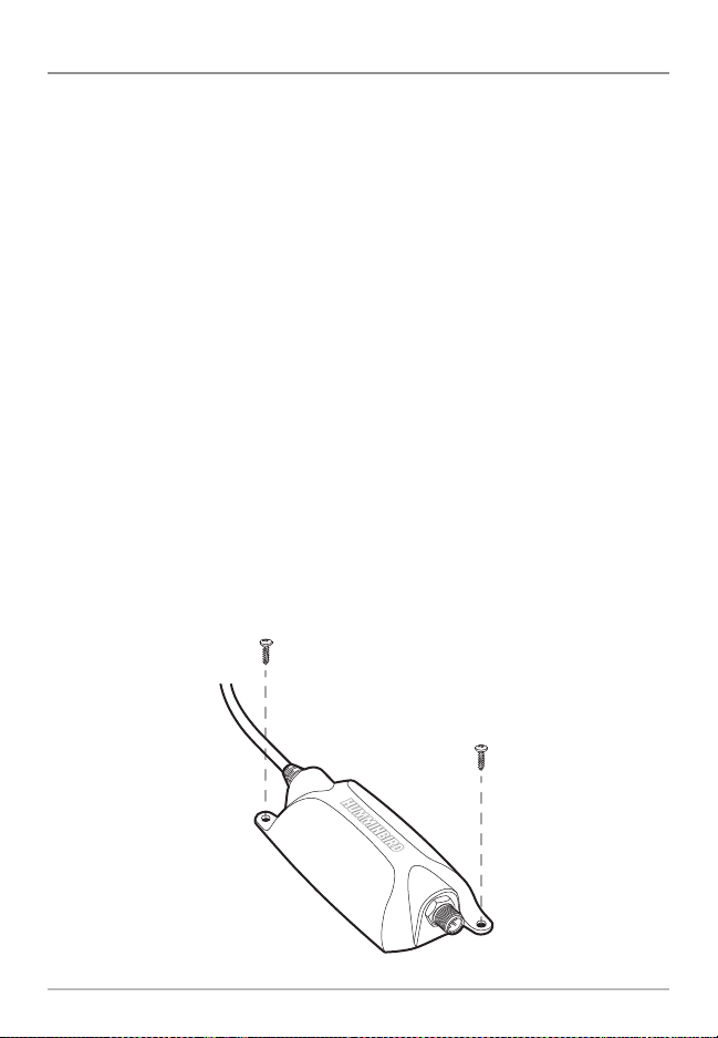
2. Install the NMEA 2000® Module
Once you have determined the mounting location, perform the following
procedures to install the NMEA 2000® Module on your boat.
1. Set the NMEA 2000® Module in place on the mounting surface. Mark
the two mounting screw locations with a pencil.
2. Set the NMEA 2000® Module aside, and drill the two mounting holes
using a 9/64” drill bit.
NOTE: On fiberglass hulls, it is best to use progressively larger drillbitsto reduce the
chance of chipping or flaking the outer coating.
NOTE: If the mountingsurface is thin or made of lightweight material, you may need
to add reinforcing material below the mounting surface in order to support the
NMEA 2000® Module.
3. Place the NMEA 2000® Module on the mounting surface and align the
screw holes with the drilled mounting holes. Insert the two #8 screws
(included) through the screw holes and into the drilled mounting
holes. Hand-tighten using a Phillips screwdriver. Hand-tighten only!
NOTE: Apply marine-grade silicone caulk or sealant (separate purchase required) to
both screws and drilled holes as needed to protect your boat from water damage.
Installing the NMEA 2000® Module
4
Installation
Page 10
Cable Connection
Use the instructions in this section to install the cables that connect the NMEA
2000® Module to your NMEA 2000® network.
NOTE: The NMEA 2000® Module does not provide power for the NMEA 2000® network.
NOTE: Only one NMEA 2000® Module can be connected to the NMEA 2000®
network at one time. See Specifications: NMEA 2000® Module Configurations
for more information.
1. Determine the System Requirements
Before connecting your NMEA 2000® Module to the NMEA 2000® network, you
must first determine the correct cable requirements for your Humminbird®
model(s).
See the cable connection information for your network configuration as
follows:
• To connect the NMEA 2000® Module to one control head, see
Single Control Head Configuration.
• To connect the NMEA 2000® Module to multiple control heads,
see Multiple Control Head Configuration.
NOTE: You may need to consult your control head installation guide for details.
2. Connect the Cables
Once you have determined your cable requirements, proceed to the section for
that configuration.
NOTE: Confirmall control heads are powered off before proceeding with the installation.
NOTE: The connectors are keyed to prevent incorrect installation, so be careful not
to force the connectors.
Cable Connection
5
Page 11

Single Control Head Configuration
Use the instructions in this section to connect the NMEA 2000® Module to one
control head. Proceed to the section that matches your Humminbird® model.
Single Control Head Configuration
1a. Connect to a 700 Series™ HD Control Head
To connect the NMEA 2000® Module to a 700 Series™ HD control head, you
will need to use an AS EC QDE Ethernet Adapter Cable.
1. Insert the AS EC QDE Ethernet cable connector into the Ethernet slot
on the 700 Series™ HD Quick Disconnect Mount Cable Collector.
700 Series™ HD Quick Disconnect Mount Cable Collector
Ethernet
NOTE: The 700 Series™HD control head uses a cable collector for the QuickDisconnect
Mount and the In-Dash Mount. See your control head installation guide for details.
6
Single Control Head Configuration
Page 12

E
Connecting the NMEA 2000® Module to a 700 Series™ HD Unit
Cable Collector
AS EC QDE Ethernet
Adapter Cable
Ethernet Port
NMEA 2000®
Module Cable
2. Connect the AS EC QDE cable connector to the NMEA 2000® Module
cable.
3. Hand-tighten the screw nut to secure the connection.
4. After completing these steps, skip ahead to procedure two, Connect
the NMEA 2000® Module to the NMEA 2000® Network.
Hand-Tightening the Screw Nut
Single Control Head Configuration
Screw
Nut
The connector is
keyed to prevent
incorrect installation.
7
Page 13
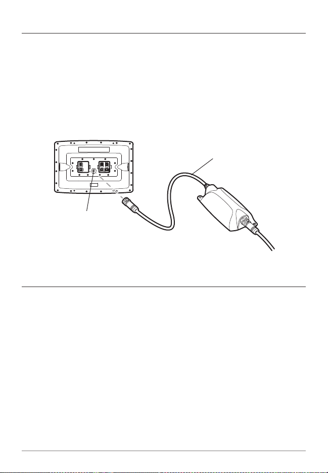
1b. Connect to an 800/900/1100 Series™ Control Head
Control heads with built-in Ethernet ports (800, 900, and 1100 Series™ units
only) can be connected to the NMEA 2000® Module directly.
1. Insert the NMEA 2000® Module cable connector into the Ethernet port
on the back of the control head.
2. Hand-tighten the screw nut to secure the connection.
Connecting the NMEA 2000® Module to an 1100 Series™ Control Head
NMEA 2000®
Module Cable
Ethernet Port
2. Connect the NMEA 2000® Module to the NMEA 2000® Network
To connect the NMEA 2000® Module to the NMEA 2000® network, you must
install a NMEA 2000® Drop Cable.
1. Plug the NMEA 2000® Drop cable connector into the NMEA 2000®
Module connector port. Hand-tighten the screw nut to secure the
connection.
2. Connect the NMEA 2000® Drop cable to a T-connector on your NMEA
2000® network (see the illustration Connecting the NMEA 2000®
Module to an Ethernet Switch).
8
Single Control Head Configuration
Page 14
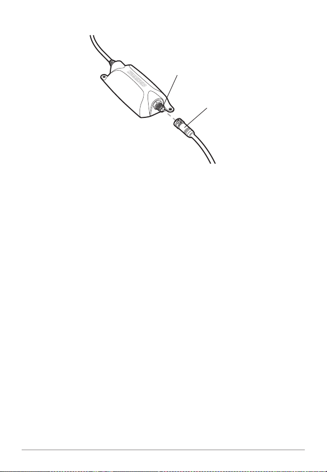
Connecting the NMEA 2000® Drop Cable to the NMEA 2000® Module
NMEA 2000®
Module
Connector Port
NMEA 2000® Drop
Cable Connector
Single Control Head Configuration
9
Page 15

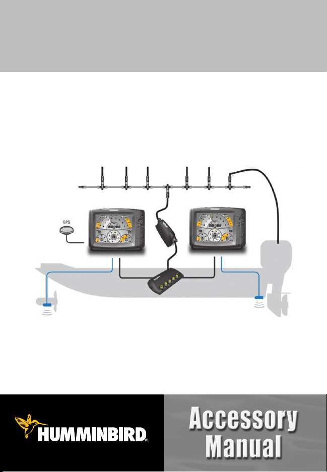
Multiple Control Head Configuration
To connect the NMEA 2000® Module to more than one control head, you will
need to install a Humminbird® Ethernet Switch. The control heads and the
NMEA 2000® Module plug into the Ethernet Switch.
Multiple Control Head Configuration
NOTE: Up to four Humminbird® control heads can be connected to the NMEA 2000®
Network via Ethernet Switch at one time.
10
Multiple Control Head Configuration
Page 16

Multiple Control Head Installation Overview
Before proceeding with this installation, review your Ethernet Switch
installation guide to understand how to install the Ethernet Switch and
connect power.
To install the NMEA 2000® Module using the Humminbird® Ethernet Switch,
you must perform the following procedures:
• Connect the control head(s) to the Ethernet Switch. See the section
that matches your Humminbird® control head model.
• Connect the NMEA 2000® Module to the Ethernet Switch.
• Connect the NMEA 2000® Module to the NMEA 2000® Network.
• Connect the Ethernet Switch power cable to a power source.
Connecting the NMEA 2000® Module to an Ethernet Switch
T-Connector
NMEA 2000®
Drop Cable
NMEA 2000®
Module Cable
Multiple Control Head Configuration
Ethernet Cables
(to the Control
Heads)
Ethernet Switch
Power Cable
11
Page 17

1a. Connect a 700 Series™ HD Control Head
to the Ethernet Switch
To connect a 700 Series™ HD control head to the Ethernet Switch, you will
need to use an AS EC QDE Ethernet Adapter Cable.
1. Insert the AS EC QDE Ethernet cable connector into the Ethernet slot
on the 700 Series™ Quick Disconnect Mount Cable Collector.
700 Series™ HD Quick Disconnect Mount Cable Collector
Ethernet
NOTE: The 700 Series™ control head uses a cable collector for the Quick Disconnect
Mount and the In-Dash Mount. See your control head installation guide for details.
2. Unscrew an Ethernet port cover from the Ethernet Switch.
3. Plug the AS EC QDE Ethernet cable connector into the port. Handtighten the screw nut to secure the connection.
1b. Connect an 800/900/1100 Series™ Control Head
to the Ethernet Switch
To connect an 800/900/1100 Series™ control head to the Ethernet Switch, you
will need to use a Humminbird® Ethernet Accessory Cable.
1. Insert the Ethernet cable connector into the Ethernet port on the back
of the control head. Hand-tighten the screw nut to secure the
connection.
2. Unscrew an Ethernet port cover from the Ethernet Switch.
3. Plug the Ethernet cable connector into the port. Hand-tighten the
screw nut to secure the connection.
12
Multiple Control Head Configuration
Page 18

Connecting the Ethernet Accessory Cable to an 1100 Series™ Control Head
Ethernet Port
Ethernet Cable
2. Connect the NMEA 2000® Module to the Ethernet Switch
1. Unscrew an Ethernet port cover from the Ethernet Switch.
2. Plug the NMEA 2000® Module cable connector into the port.
Hand-tighten the screw nut to secure the connection.
Connecting Ethernet Cable Connectors to the Ethernet Switch
Keep port covers fastened
over unused ports
Ethernet Cable
Ethernet Switch
Power Cable
NOTE: See the illustration, Connecting the NMEA 2000® Module to an
Ethernet Switch, for more details.
Multiple Control Head Configuration
13
Page 19

3. Connect the NMEA 2000® Module to the NMEA 2000® Network
To connect the NMEA 2000® Module to the NMEA 2000® network, you must
install a NMEA 2000® Drop Cable.
1. Plug the NMEA 2000® Drop cable connector into the NMEA 2000®
Module connector port. Hand-tighten the screw nut to secure the
connection.
2. Connect the NMEA 2000® Drop cable to a T-connector on your NMEA
2000® network (see the illustration Connecting the NMEA 2000®
Module to an Ethernet Switch).
Connecting the NMEA 2000® Drop Cable to the NMEA 2000® Module
NMEA 2000®
Module
Connector Port
NMEA 2000® Drop
Cable Connector
4. Connect the Ethernet Switch Power Cable to Power
See your Ethernet Switch installation guide for instructions.
14
Multiple Control Head Configuration
Page 20

Powering On
Follow the instructions below to power on your Humminbird® control head(s).
To Power On:
1. Press the POWER/LIGHT key.
2. When the Title screen is displayed, press the MENU key to access the
Start-Up Options Menu.
3. Use the 4-WAY Cursor Control key to select Normal (if there is a
transducer attached to the control head) or Simulator (if there isn’t a
transducer attached to the control head).
• If a functioning transducer is connected, Normal operation will be
selected automatically at power up, and your Fishfinder can be
used on the water.
• If a transducer is not connected and you wait too long to select a
Start-Up Option, the system will default to whichever menu is
already highlighted.
• In Simulator you can learn how to use your control head and save
settings in advance for later use.
NOTE: See your control head operations manual for more information about the
Start-Up Options Menu.
NOTE: If you have an InterLink™ connected to the network, the NMEA 2000® will
disable the InterLink™ because both network systems cannot be used at the same time.
Powering On
15
Page 21

System Setup
Confirm all control heads and accessories on your NMEA 2000® network are
powered on and operating. Proceed to the following sections to configure your
control head(s) to recognize the connected equipment and sensors on the
NMEA 2000® Network:
• Selecting NMEA 2000® Data Sources
• Selecting NMEA 2000® GPS Sources
• Setting Alarms
• Displaying and Using NMEA 2000® Views
16
System Setup
Page 22

NMEA 2000® Data Sources Setup
When the NMEA 2000® Module is first installed and connected on the NMEA
2000® network, the control head(s) will automatically detect all connected
NMEA 2000® sources (engines, tanks, depth sounders, etc.). The available
sources are added to the Accessories menu tab, under NMEA2K Gateway.
NOTE: NMEA 2000® menus and menu options are displayed as NMEA2K.
• Source Setup: Use the NMEA2K Gateway menu to select the sources
that will provide data for the digital readouts in the NMEA 2000® Views.
The changes you make are saved even after the unit is powered off.
NOTE: If there is only one source connected on the NMEA 2000® network, that
source will be automatically selected.
• GPS Source Setup: When you power on the network for the first time,
the control head will automatically choose a connected or internal GPS
receiver to provide data to the control head. To use a GPS receiver that
is installed on the NMEA 2000® network, it must be manually selected
from the Network Source Setup dialog box. See NMEA 2000® GPS
Source Setup for more information.
• Control Head(s): The Sources and GPS Source have to be set up on
each control head on the network.
• Lost Data Source: If the control head cannot detect the selected
NMEA 2000® data source, the digital readout box will go blank in
NMEA 2000® Views.
• NMEA 2000® PGN Messages: The NMEA 2000® PGNs are listed in the
Specifications section of this manual.
NMEA 2000® Data Sources Setup
17
Page 23

1. Select NMEA 2000® Data Sources
1. Main Menu: Press the MENU key twice.
Select the Accessories menu tab.
NOTE: In NMEA2K Views, press the MENU key once
to open the Main Menu (see Views).
2. Select NMEA2K Gateway. Press the RIGHT
Cursor key to open the NMEA2K Sources
menu.
3. Press the DOWN or UP Cursor key to select
a source group.
4. Press the RIGHT Cursor key to open the
submenu for that source.
5. Press the DOWN or UP Cursor key to select a
data source. Press the RIGHT Cursor key or
NMEA2K Sources Menu
NOTE: If your control head does not have a CHECK/INFO key, press the top
VIEW PRESET key .
6. Press the EXIT key to return to the NMEA2K Sources menu.
7. Repeat steps 3 - 6 to select another data source.
CHECK/INFO key to select the data source.
8. Repeat steps 1 - 7 for each control head on the network where you
want to view NMEA 2000® data.
NMEA2K Sources Menu: Attitude Sources Submenu
Press the RIGHT
Other available
sources on the
NMEA 2000®
network.
NOTE: If a sensor is not detected during the configuration, confirm thatthepower source
for the device is turned on, or check the installation and cable connection.
18
NMEA 2000® Data Sources Setup
Cursor key or the
CHECK/INFO key
to select a
NMEA2K source.
Page 24

2. Set NMEA 2000® Data Offsets
Use the NMEA2K Data Offset menu option to adjust digital readouts by the
amount you set. For example, use Depth Adjustment to adjust the digital depth
readout to indicate depth from the waterline or the boat’s keel.
To Set a Data Offset:
1. Main Menu: Press the MENU key twice. Select the Setup menu tab.
NOTE: In NMEA2K Views, press the MENU key once to open the Main Menu
(see Views).
2. Select NMEA2K Data Offset. Press the RIGHT Cursor key to open the
submenu.
3. Select a data option. (Depth Adjustment, Heading Adjustment, Temp
(Water) Adjustment, STW Adjustment)
4. Press the LEFT and RIGHT Cursor keys to adjust the setting.
5. Close: Press the EXIT key.
3. Select Units of Measurement for NMEA 2000® Readouts
(International models only)
Use this section to set the system display preferences for your NMEA 2000®
digital readouts.
NOTE: The Setup menu tab includes various menu options to display units for depth,
temperature, distance, and speed. See your control head operations manual for more
information about setting display preferences.
To Select Units of Pressure:
1. Main Menu: Press the MENU key twice. Select the Setup menu tab.
NOTE: In NMEA2K Views, press the MENU key once to open the Main Menu
(see Views).
2. Select Units - Pressure.
3. Select a setting. (inHg/PSI, hPa/kPa)
4. Close: Press the EXIT key.
NMEA 2000® Data Sources Setup
19
Page 25

To Select Units of Volume:
1. Main Menu: Press the MENU key twice. Select the Setup menu tab.
NOTE: In NMEA2K Views, press the MENU key once to open the Main Menu
(see Views).
2. Select Units - Volume.
3. Press the LEFT or RIGHT Cursor key to select a setting. (U.S. Gallons,
Liters)
4. Close: Press the EXIT key.
20
NMEA 2000® Data Sources Setup
Page 26

Network Menu Tab
When a control head is connected to the
NMEA 2000® Module, the Network menu
tab is added to the Main Menu system.
The Network menu tab includes the following menu options:
• Unit Name: Displays the name of the control head. The default Unit
Name is based on its model number and serial number. To change the
Unit Name, see Customize the Unit Name.
• Network Source Setup: Opens the Network Source Setup dialog box.
The Network Source Setup dialog box displays all sonar, temperature,
and GPS sources detected on the network. The sources may be shared
on the network or operating locally with their connected control head.
NOTE: The Sonar and Temperature Sources in this dialog box are not NMEA 2000®
sources. For NMEA 2000®network purposes, you will onlyneedtoopen the Network
Source Setup dialog box to select a NMEA 2000® GPS source. See NMEA 2000®
GPS Source Setup.
Network Menu Tab
21
Page 27

Customize the Unit Name
Each control head is assigned a Unit Name, which is based on its model
number and serial number. The unit name is also displayed next to a source
name in the Network Source Setup dialog box so you can see where the source
is connected.
When you’re first setting up your network, you may want to change how the
unit name is displayed, so it is easier to identify each unit on the network.
Unit Name Dialog Box
Name Field
Select Save and
press the RIGHT
Cursor key.
Use the 4-WAY Cursor
Control key to change
the unit name.
To Customize the Unit Name
:
1. Main Menu: Press the MENU key twice. Select the Network menu tab.
NOTE: In NMEA2K Views, press the MENU key once to open the Main Menu
(see Views).
2. Select Unit Name. Press the RIGHT Cursor key. The unit name is
displayed in the dialog box.
3. Use the 4-WAY Cursor Control key to select the Name field. You can
change the control head display name as follows:
Move within the Name Field: Press the RIGHT or LEFT Cursor key.
Change a Letter or Number: Press the UP and DOWN Cursor keys. All
upper and lower case letters are available (including digits 0-9 and
some punctuation characters).
4. Save: Use the 4-WAY Cursor Control key to choose Save, and then
press the RIGHT Cursor key.
5. Repeat steps 1 - 4 for each control head on the network.
22
Network Menu Tab
Page 28

NMEA 2000® GPS Source Setup
When you power on the control head for the first time, it will automatically
choose the connected or internal GPS receiver to provide data to the control
head. To use a NMEA 2000® GPS source connected on your NMEA 2000®
network, the source must be manually selected from the Network Source
Setup dialog box.
• Digital Readouts: To provide digital readout data for NMEA2K views,
select a NMEA 2000® GPS Source.
• Humminbird® Views: The NMEA 2000® GPS source will display data in
Sonar Views, Chart Views, Bird’s Eye View, etc. It is the only NMEA
2000® source that can display data outside NMEA2K views.
• Multiple Control Heads: If you have more than one unit connected via
Ethernet Switch, you must select the NMEA 2000® GPS on each control
head.
• Menu System and Views: When you select a NMEA 2000® GPS
source, the menu settings, view rotation, and digital readouts will
automatically update on the control head.
1. Select a NMEA 2000® GPS Source
Use the instructions below to select a NMEA 2000® GPS source for your control
head.
To Select a NMEA 2000® GPS Source:
1. Main Menu: Press the MENU key twice. Select the Network menu
tab.
NOTE: In NMEA2K Views, press the MENU key once to open the Main Menu
(see Views).
2. Select Network Source Setup, and press the RIGHT Cursor key.
3. Press the RIGHT Cursor key until the GPS tab is selected.
4. Scroll: Press the DOWN or UP Cursor keys. The selected source is
highlighted in white.
NMEA 2000® GPS Source Setup
23
Page 29

5. Select: Press the RIGHT Cursor key. The check mark indicates that the
source is being used by the control head.
6. Save: Press the EXIT key twice to close the dialog box. Network
settings are saved even after the unit is powered off.
7. Repeat steps 1 - 6 for each control head on the network.
Selecting a NMEA 2000® GPS Source
GPS tab
The control
head detects
all of the GPS
sources in the
network.
Unit Name
Column
(see Customize
the Unit Name)
Unit Model
Number
Column
GPS Type
Column
(Internal,
External, or
NMEA2K)
GPS Fix
Column
Selected
The check mark
indicates the
source is used by
the control head.
Empty
The empty box
indicates the GPS
data is available
but not selected.
NOTE: The current GPS Fix Type is reported as No Fix, Fixed, or Enhanced. An Enhanced
fix has been augmented using information from WAAS, EGNOS, or MSAS.
24
NMEA 2000® GPS Source Setup
Page 30

Confirm and Change a Lost NMEA 2000® GPS Source
• NMEA2K Views: If the control head cannot detect the set NMEA
2000® GPS receiver, the digital readout boxes will go blank in NMEA2K
Views. See Select a NMEA 2000® GPS Source to select another GPS
receiver in the network.
• Humminbird® Views (Sonar Views, Chart Views, etc): If the control
head cannot detect the set NMEA 2000® GPS receiver, it will
automatically select another available GPS source. If no local GPS
source is available, the digital readout boxes will flash. Open the
Network Source Setup dialog box to check connections and select a
new GPS source.
NOTE: To change a source after the network has been configured, open the Network
Source Setup dialog box and change a GPS source at any time (see NMEA 2000® GPS
Source Setup). Network settings are saved even after the unit is powered off.
NMEA 2000® GPS Source Setup
25
Page 31

Set Alarms
Alarms are based on the limits you set for a
device such as battery voltage, depth, water
temperature, and more. Installing and
connecting the NMEA 2000® Module adds
the following NMEA 2000® Alarms to the
Alarms Menu tab:
• NMEA2K Depth
• NMEA2K Environment
• NMEA2K Engine
1100 Series™ Alarms Menu Tab
Each group expands into a submenu, which lists the alarms that fall under that
group. See the NMEA 2000® Alarms Table at the end of this section for a
complete list of NMEA 2000® alarms.
NMEA2K Depth
Alarms
NMEA2K Depth Alarm Submenu
1. Set NMEA2K Alarms
1. Main Menu: Press the MENU key twice. Select the Alarms menu tab.
NOTE: In NMEA2K Views, press the MENU key once to open the Main Menu
(see Views).
2. Select a NMEA2K alarm group. (NMEA2K Depth, NMEA2K Environment,
NMEA2K Engine)
3. Press the RIGHT Cursor key to open the submenu.
4. Press DOWN or UP Cursor key to select an alarm.
5. Press the RIGHT or LEFT Cursor Key to adjust the alarm setting.
6. Close: Press the EXIT key to return to the Alarms menu.
26
Set Alarms
Page 32

7. Repeat steps 2 - 6 to set another alarm.
NOTE: See your control head operations manual for full alarms menu settings.
NOTE: When an alarm is triggered, you can silence it by pressing any key. The alarm will
be silenced, and will not be triggered again until a new instance of the alarm condition is
detected.
Confirm an Alarm
When an alarm is triggered in the system, an alert will display on-screen.
To acknowledge the alarm, press any key on the control head.
NMEA2K Depth Alarm Notification Box, 1100 Series™
The name of the
alarm triggered
appears on the
screen. Press any
key to confirm and
silence the alarm.
Set Alarms
27
Page 33

NMEA 2000® Alarms Table
Menu Alarm Name Range
NMEA2K Depth
NMEA2K Shallow Water
Off, 1 – 330 feet,
0.5 – 100.0 meters*, or
0.1 – 55 fathoms;
Default = Off
NMEA2K Deep Water
Off, 1 – 330 feet,
0.5 – 100.0 meters*, or
0.1 – 55 fathoms;
Default = Off
Off, - 40°F – +140° F or
- 40°C – + 60° C*;
Default = Off
NMEA2K Environment
NMEA2K Temperature (Air)
Off, 33°F – 120°F or
1° C – 50°C*;
Default = Off
NMEA2K Temperature (Water)
Off, 1% – 100%;
Default = Off
NMEA2K Engine
Total Fuel
Check Engine
Off, On; Default = Off
Off, On; Default = Off
Engine Over Temperature
Off, On; Default = Off
Engine Low Oil Pressure
Off, On; Default = Off
Engine Low Oil Level
Off, On; Default = Off
Engine Low Fuel Pressure
Off, On; Default = Off
Engine Low System Voltage
Off, On; Default = Off
Engine Low Coolant Level
Off, On; Default = Off
Engine Water Flow
Off, On; Default = Off
Engine Charge Indicator
* International models only.
28
Set Alarms
Page 34

Views
When the NMEA 2000® Module is connected to your Humminbird® control
head, new views and menus will be added to the control head.
• NMEA2K Views are added to the views rotation and the Views menu
tab.
• Views X-Press™ Menu will become available, allowing you to easily
access all views. See Views X-Press™ Menu for more information.
• Digital Readouts on the NMEA2K views can be customized.
NOTE: In NMEA2K Views, press the MENU key once to open the Main Menu.
Views
29
Page 35

NMEA2K Data Box View
NMEA2K Data Box View presents a full screen view of digital data boxes. It
automatically displays a default data set, and you can also select a data
readout for each data box. See Select Readouts for NMEA2K Views for more
information.
NOTE: The view must be displayed on the screen in order to change the digital
readouts. The availability of the digital readout information varies by model.
700 Series™ HD Data Box View
1
3
5
Engine 1 Temperature
1
Engine 2 Temperature
2
3
Speed Over Ground (SOG)
2
4
6
NMEA2K Depth
Course Over Ground (COG)
Heading (Hdg)
4
5
6
30
Views
Page 36

NMEA2K Gauge View
NMEA2K Gauge View presents a full screen view of gauges and data boxes.
It automatically displays a default data set, and you can select the data
readouts for the gauges and data boxes. See Select Readouts for NMEA2K
Views for information.
NOTE: The view must be displayed on the screen in order to change the digital
readouts. The availability of the digital readout information varies by model.
• Gauges display data both graphically and numerically.
800/900 Series™ Gauge View
1
2
3
4
TrueWindSpeed (TWS)
1
Apparent Wind Angle (AWA)
2
3
Engine 1 Temperature
4
Engine 2 Temperature
Engine 1 Tachometer (Gauge & Digital Readouts)
5
Views
5
7
9
Engine 2 Tachometer (Gauge & Digital Readouts)
Speed Over Ground (SOG) (Gauge & Digital Readouts)
Speed Through Water(STW)(Gauge& Digital Readouts)
Course Over Ground (COG) (Gauge & Digital Readouts)
Heading (Hdg) (Gauge & Digital Readouts)
6
8
10
6
7
8
9
10
31
Page 37

NMEA2K One Engine View
NMEA2K One Engine View presents a full screen view of gauges, which
allows you to monitor fuel level, engine temperature, and RPMs from one
engine connected on your NMEA 2000® network. The RPM readout is fixed in
this view, and you can select the data readouts for the other gauges. See
Select Readouts for NMEA2K Views for more information.
NOTE: The view must be displayed on the screen in order to change the digital
readouts. The availability of the digital readout information varies by model.
• Engine Tachometer (Tach) is a fixed gauge on the view.
• A Check Engine (Service) Icon will display in the Engine Tachometer
readout when engine conditions require attention (See 1100 Series™
Double Engine Monitoring View).
1100 Series™ Single Engine Monitoring View
4
2
3
7
6
Engine 1 Tachometer (Gauge & Digital Readouts [fixed])
1
Engine 1 Fuel Tank Level
2
3
Engine 1 Temperature
4
Air Temperature
Speed Over Ground (SOG) (Gauge & Digital Readouts)
1
5
Water Temperature
Heading (Hdg) (Gauge & Digital Readouts)
Engine 1 Fuel Rate (Gauge & Digital Readouts)
32
8
5
6
7
8
Views
Page 38

NMEA2K Two Engine View
NMEA2K Two Engine View presents a full screen view of gauges, which
allows you to monitor fuel level, engine temperature, and RPMs from two
engines connected on your NMEA 2000® network. The RPM readout is fixed in
this view, and you can select the data readouts for the other gauges. See
Select Readouts for NMEA2K Views for information.
NOTE: The view must be displayed on the screen in order to change the digital
readouts. The availability of the digital readout information varies by model.
• Engine Tachometer (Tach) is a fixed gauge on the view.
• A Check Engine (Service) Icon will display in the Engine Tachometer
readout when engine conditions require attention (See 1100 Series™
Double Engine Monitoring View).
1100 Series™ Double Engine Monitoring View
Views
3
5
7
Engine 1 Tachometer (fixed)
1
Engine 2 Tachometer (fixed)
2
3
Engine 1 Fuel Tank Level
4
Engine 2 Fuel Tank Level
Engine 1 Temperature
5
1
2
10
1
8
Speed Over Ground (SOG) (Gauge & Digital Readouts)
Heading (Hdg) (Gauge & Digital Readouts)
Engine 1 Fuel Rate (Gauge & Digital Readouts)
33
2
6
Engine 2 Temperature
Check Engine (Service) Icon
4
9
6
7
8
9
10
Page 39

Display NMEA2K Views
Display NMEA2K Views using the following methods:
• Cycle: When you press the VIEW key repeatedly, the display cycles
through the available views on your screen. When you press the EXIT
key, the display cycles through the available views in reverse order.
• Views X-Press™ Menu: Press and hold the VIEW key. The Views
X-Press™ Menu organizes all available views into groups so that you
can display a view quickly.
Display a View On-Screen Using the
Views X-Press™ Menu
The Views X-Press™ Menu provides a shortcut to all available
views so you can find and display a view quickly.
To Display a View Using the Views X-Press™ Menu:
1. Press and hold the VIEW key until the Views X-Press™
Menu displays on the screen.
2. Press the DOWN or UP Cursor key to select a group
(Sonar, Chart, Radar, Data, System), and press the
RIGHT Cursor key.
Views X-Press™
Menu
NOTE: If your control head does not have a CHECK/INFO key, press the top VIEW
PRESET key .
3. Select a View, and press the RIGHT Cursor key or the
CHECK/INFO key to display that view.
Select a View and
press the RIGHT
Cursor key or the
CHECK/INFO key to
immediately
display that view.
Views X-Press™ Menu: Data Views Submenu
NOTE: When a view is selected and displayed through the Views X-Press™ Menu, that
view will automatically be set to “Visible” under the Views menu tab.
34
Views
Page 40

Select Readouts for NMEA2K Views
Installing and connecting a NMEA 2000® Module adds additional data sets to
the Select Readouts menu. To customize data items displayed within each
NMEA2K view, see the instructions below.
NOTE: To customize the digital readouts in a NMEA2K view, the view must be displayed
on the screen when you open the Select Readouts menu. The availability of the digital
readout information varies by model.
To Select Readouts:
1. Main Menu: Press the MENU key once. Select the Setup menu tab.
2. Press the UP or DOWN Cursor key to select Select Readouts. Press the
RIGHT Cursor key to open the Select Readouts submenu.
NOTE: If the Select Readouts menu option does not appear under the Setup Menu
tab, change the User Mode to Advanced.
3. Press the UP or DOWN Cursor key to select a Readout position, then
press the RIGHT or LEFT Cursor key to select a data subgroup.
4. Press the CHECK/INFO key to open the submenu for that data group.
NOTE: If your control head does not have a CHECK/INFO key, press the top VIEW
PRESET key .
5. Press the UP or DOWN Cursor key to select a data option, and press
the RIGHT Cursor key or the CHECK/INFO key to display that data in
the readout position.
NOTE: If your control head does not have a CHECK/INFO key, press the top VIEW
PRESET key .
NOTE: The selected readout will immediately display on the screen.
6. Press the EXIT key to return to the Select Readouts menu.
NOTE: See your control head operations manual for more information about
selecting readouts.
NOTE: Certain NMEA2K Views have fixed digital readouts that cannot be
customized. See Views for more information.
Views
35
Page 41

Select a Readout
Position. Use the
LEFT or RIGHT
Cursor key to
select a data
group.
Engine 1 Submenu
Select a Data
Option and press
the RIGHT Cursor
key or the
CHECK/INFO key
to select.
Selecting a Readout Position,
1100 Series™ Gauge View
Selecting Data for the Readout Position,
1100 Series™ Gauge View
36
Views
Page 42

Troubleshooting
Before contacting the Humminbird® Customer Resource Center, please read
the following section. Taking the time to review these troubleshooting
guidelines may allow you to solve a performance problem yourself, and
therefore avoid sending your unit back for repair.
Fishing System Doesn’t Power Up
If your Fishing System doesn’t power up, use the installation guide that is
included with your Fishing System to confirm specific details, making sure that:
• the power cable is properly connected to the Fishing System control head,
• the power cable is wired correctly, with red to positive battery terminal
and black to negative terminal or ground,
• the fuse is operational,
• the battery voltage of the power connector is at least 10 Volts, and
Correct any known problems, including removing corrosion from the battery
terminals or wiring, or actually replacing the battery if necessary.
Fishing System Defaults to Simulator with a Transducer Attached
A connected and functioning transducer will cause the newly-started Fishing
System to go into Normal operating mode automatically. If, when you power
up the Fishing System, it goes into Simulator mode automatically, even though
a transducer is already connected, this means that the control head is not
detecting the transducer. Perform the following troubleshooting tasks:
• Using the Installation Guide that also comes with your Fishing System,
check to make sure that the transducer cable is securely connected to
the Fishing System. Reconnect if necessary, and power up the Fishing
System again to see if this fixes the problem.
• Replace the non-functioning transducer with a known good transducer
if available and power up the control head again.
• Check the transducer cable. Replace the transducer if the cable is
damaged or corroded.
Troubleshooting
37
Page 43

Specifications
059392 ISO Acknowledgement
• •
059904 ISO Request
• •
060928 ISO Address Claim
• •
126208 NMEA - Request Group Function
• •
126992 System Time
•
126996 Product Information
•
•
127250 Vessel Heading
•
127251 Rate of Turn
•
127257 Attitude
•
127258 Magnetic Variation
•
127488 Engine Parameters, Rapid Update
•
127489 Engine Parameters, Dynamic
•
127505 Fluid Level
•
128267 Water Depth
•
128275 Distance Log
•
129026 COG & SOG, Rapid Update
•
129029 GNSS Position Data
•
129033 Time & Date
•
129539 GNSS DOPs
•
129540 GNSS Sats in View
•
130306 Wind Data
•
130310 Environmental Parameters
•
130311 Environmental Parameters
•
130312 Temperature
•
130313 Humidity
•
130314 Actual Pressure
•
Message (PGN) Description Input Output
126464
• •
Receive/Transmit PGN’s Group Function
NMEA 2000® Sentences Table:
38
Specifications
Page 44

NMEA 2000® Module Configurations
Only one Humminbird® NMEA 2000® Module can be connected to a single
NMEA 2000® network at one time, as shown in the graphics below.
Supported Configuration Example 1
Single Control Head Configuration - Connect the NMEA 2000® Module
to one NMEA 2000® network and one Humminbird® control head.
Supported Configuration Example 2
Multiple Control Head Configuration Using One Ethernet Switch - Connect the NMEA 2000®
Module to one NMEA 2000® network and one Humminbird® Ethernet Switch. Up to four
Humminbird® control heads can be connected to the Ethernet Switch.
Specifications
39
Page 45

Humminbird® does not support the following configurations:
Do not connect two NMEA 2000® Modules to one Humminbird®Ethernet Switch.
Do not connect two NMEA 2000® Modules to one NMEA 2000® network.
40
Specifications
Page 46

Contact Humminbird®
Contact the Humminbird® Customer Resource Center
in any of the following ways:
By Telephone:
(Monday - Friday 8:00 a.m. to 4:30 p.m. Central Standard Time):
1-800-633-1468
By e-mail:
(typically we respond to your e-mail within three business days):
service@humminbird.com
For direct shipping, our address is:
Humminbird
Service Department
678 Humminbird Lane
Eufaula, AL 36027 USA
41
 Loading...