

Page 1
MACHT’S MÖGLICH
Operating Instruction
Horse Trailer
Part 2
7000 Series
en
humbaur.com
Page 2

Humbaur GmbH
Mercedesring 1
86368 Gersthofen
Germany
Your dealer
Name
Address
Telephone
E-mail
Please enter the name of your dealer.
Please complete the service card on the reverse side of the "Trailers up to 3.5 to" General Part 1 operating instructions and send it to Humbaur GmbH.
Ask for the handover inspection to be recorded when accepting your trailer.
@
Your trailer:
Model
Type (abbreviation)
Vehicle
Identification
Number (VIN)
Registration number
Please enter your trailer type and the identification.
You will find the dimensions / technical data of your trailer in the
vehicle documents.
MACHT’S MÖGLICH
Page 3
MACHT’S MÖGLICH
Not
es on use
Contents of this operating instruction manual
This operating instruction manual must be carefully read,
understood and complied with in full by anyone who is
responsible for the Humbaur GmbH vehicle and its
modules.
Humbaur GmbH accepts no liability for damage or failures
which arise through disregard of this manual!
Read and observe the operating instruction manual
with all the instructions, warnings and notes before
driving for the first time!
Please note that all illustrations are representative
and may differ from the actual appearance /
equipment.
Also read and observe the instruction manuals for
components such as axles, etc.!
PART 2
This operating instruction manual “Part 2 - Horse trailer” is
intended for you as the user of a ready-to-use trailer.
It provides detailed instructions for handling a horse trailer
and its specific accessories.
It contains supplementary information on safe operation,
care/cleaning, maintenance/servicing,
troubleshooting and decommissioning/disposal of the
trailer.
PART 1
For all other general information on trailers up to 3.5 to, see
the operating instruction manual, “Trailers up to 3.5 to
(General Points – Part 1).”
This specific operating instruction manual (Part 2) for your
trailer is provided on the enclosed CD. You can also
download it from www.humbaur.com in the section:
Downloads – Operating manuals
The complete technical documentation is part of the product
and should be kept in the driver's cab of the traction unit for
reference at all times.
Key details for the handling, operation and the requisite
care and maintenance work of the trailer are referred to in
this operating instruction manual, and errors can only be
avoided and trouble-free operation guaranteed if you are
familiar with them.
Errors excepted. The manufacturer:
Humbaur GmbH
Mercedesring 1
89368 Gersthofen (Germany)
reserves the right make technical changes to the design,
equipment and accessories with respect to the information
and illustrations in the operating instruction manual.
As a result, no claims whatsoever can be derived from the
information, illustrations and descriptions.
Obligations of the operator
The trailer may only be operated in perfect condition.
Ensure that the operating instruction manual is included
with the trailer e.g. if it is sold.
Only utilise trained or instructed personnel.
Ensure that the operating instruction manual is
complied with in all life cycle phases of the trailer
and that the prescribed personal protective
equipment is worn.
Provide the requisite operating and auxiliary materials.
User group
The trailer should only be operated by users who possess
the following additional prerequisites and knowledge:
Experience in handling horses.
Transport of horses.
3
Page 4

Contents of this operating instruction manual
MACHT’S MÖGLICH
Keyword index
Use the keyword index from page 5 to search for specific
topics.
Refer to the technical documentation of the
installed components for additional information.
1 Safety
You will find safety information for the correct handling of
the trailer in the "Safety" chapter from page 7.
Read this chapter before driving for the first time.
2 General information
You will find details on vehicle identification in the "General
information" chapter from page 11.
3 Operation
The chapter about "Operation", starting on page 23,
provides you with information about loading and unloading,
securing the horse, caring for the horse and duly securing
the trailer to prevent it from rolling.
4 Operating the chassis
The chapter on "Chassis Operation", starting on page 37,
tells you all you need to know about carriage transport.
5 Operating the body
The chapter on the "Body", starting on page 43, explains
how to operate the body correctly, how to open, close and
secure windows, doors and hoods, as well as how to
operate the interior accessories.
8 Troubleshooting guide
You will find information on troubleshooting and important
service addresses in the "Troubleshooting guide" from page
95.
4
6 Electrical system
You will find information on the lighting in the chapter on the
"Electrical system" from page 81.
7 Testing, care and maintenance
You will find out more about the work required to maintain
operational safety and the value of your vehicle in the
chapter on "Testing, care and maintenance" from page 85.
Page 5

MACHT’S MÖGLICH
Keywords
A
Access door
Door holder 45
Address
Manufacturer
Service 96
Spare parts 96
B
Body
43
Breast and breech bar
Panic locking
with central partition wall 74
C
Care
85
Carriage frame 39
Central partition wall, 76
pivoting 79
simple 76
Chapter
Electrical system
General information 11
Operating the body 43
Operating the chassis 37
Operation 23
Safety 7
Testing, care and maintenance 85
Troubleshooting guide 95
Chassis
Handling
Contact
Humbaur Service Partners
Parts logistics 96
52
3
75
81
37
96
Technical customer service 96
D
Deflector
Disclaimer 9
Door holder 45
for hooking-in 45
to press in 45
Driving with the towing vehicle and trailer 23
E
Electrical system
F
Foal grid
Fold-out flap 54
Front exit 53
Fold-out flap 54
must be folded down 54
G
General information
GFR tailgate 58
H
Handle for manoeuvring
Handling
Body
Chassis 37
Head partition 78
Humbaur Service addresses 96
I
Information on loading
Intended use 8
56
81
60
11
33
43
26
L
Lights
82
interior 83
outside 82
Saddle compartment lighting 83
Load securing 28
Basic principles 28
Securing a carriage 30
Securing a horse 29
Tie-down points 30
Loading 26
M
Maintenance
Manoeuvring 33
Manufacturer 3, 8
Model overview 18
N
Notes
Operating Instruction Manual
O
Operation
P
Panic locking
Q
Qualification of the personnel
R
Revolving door
Roll-up tarpaulin 56
Roof vent / skylight 71
85
3
23
75
8
66
5
Page 6

MACHT’S MÖGLICH
Rotary flaps 62
S
Saddle compartment
Saddle holder 47
Saddle compartment (Notos PLUS)
Power connection
Step 38
Saddle compartment cubicle 49
Saddle compartment lighting 83
Safety 7, 10
Body area 10
Chassis area 10
Securing a carriage 30
Securing a horse 29
Service address 96
Sources of danger 10
Spare parts address 96
Spare wheel 87
Start of the journey 10
Step 38
Step (Notos PLUS) 38
Stichwörter 5
46
84
Unloading
Use
Foreseeable misuse
Intended 8
V
Vent window
Positions 69
Ventilation window (Notos ALU) 72
26
8
69
Zugösen-Verbindung 235
T
Tailgate
Testing 85
Tie-down points 30
Towing the trailer 33
Track width 26
Troubleshooting 95
Troubleshooting guide 95
Tyre types 87
U
6
64, 65
Page 7

MACHT’S MÖGLICH
1
Safety
7
Page 8

1
MACHT’S MÖGLICH
Use
Intended use
The following are permitted:
– Transport of horses, donkeys, ponies.
– Transport of horse accessories (e.g. saddle, blankets,
cleaning utensils, etc.).
– Carriage transport on the carriage frame only.
Qualification of the personnel
HUMBAUR vehicles and bodies and their
operating components may only be used and maintained by
personnel who are aware of:
– this operating instruction manual.
– the trailer and the associated traction unit.
– the operating and maintenance instructions of the
suppliers.
– the German Road Traffic Act (StVO) and German Road
Traffic Licensing Regulations (StVZO).
– all the respective health and safety / accident prevention
regulations as well as other safety, occupational health
and road traffic regulations.
– knowledge about transporting horses, donkies and
ponies.
– knowledge about the Animal Protection Ordinance.
Reasonably foreseeable misuse
Any use extending beyond the prescribed transport
applications is regarded as other than intended.
In particular, this includes:
General
– Non-observance of the safety instructions in the
operating instruction manual “Trailers up to 3.5 to, Part
1 - General”.
– Transport of persons.
– Transport of small animals (e.g. sheep, pigs, etc.) - see
Animal Protection Ordinance.
– Transport of foals / small horses without a foal grid
installed.
– Driving with insufficient load securing.
– Driving with unlocked flaps / doors.
– Driving with open deflector / roll-up tarpaulin.
– Driving with breast and breech bar not inserted or not
secured.
– Driving without central partition wall installed / secured.
– Irregular cleaning of the cargo bed / internal space.
– Exceeding the drawbar load and trailer load.
– Transport of other loads - without load securing.
Notos (with saddle compartment)
– Loading a horse without previously opening the front
flap (no panic unlocking possible from the inside).
– Driving with unsecured centre-post partition wall.
Notos PLUS (with saddle compartment cubicle)
– Transport of unsecured goods in the saddle
compartment cubicle.
The manufacturer:
Humbaur GmbH
Mercedesring 1
86368 Gersthofen (Germany)
rejects any damage which arises through disregard of this
manual – the risks are borne solely by the user.
8 Safety
Carriage trailer
– Transporting a carriage when the trailer is not loaded.
– Driving with unsecured carriage.
– Loading / unloading the trailer with incorrectly set track
width on the loading ramps.
Page 9

MACHT’S MÖGLICH
Disclaimer
Any liability of the manufacturer becomes null and void if:
– the trailer and its components are altered without
authorization.
– the original parts or conversion parts / accessories
approved by Humbaur GmbH are replaced by other
components.
– retrospective changes have been made to the trailer
(e.g. new drill holes in the frame or the reboring of
existing drill holes in the frame). This is considered by
Humbaur GmbH to be a structural change, and the type
approval therefore becomes null and void.
– non-approved accessories or third-party spare /
component parts which are not original HUMBAUR
parts are attached or installed. The type approval of the
trailer, possibly even the insurance cover, becomes null
and void.
– care and maintenance intervals prescribed by the
manufacturer are not complied with.
Any risks and liability exclusions resulting from this also
exist if:
Use
1
– Acceptance inspections have been carried out by
inspectors / authorised experts of the technical
inspection authorities or officially recognised
organisations.
– Official approvals are available.
9Safety
Page 10

1
MACHT’S MÖGLICH
Check, adjust and secure before each journey
Safety first!
Sources of danger
Take note of the following points without fail:
– Coupling and uncoupling a trailer: Standing in the
danger area is prohibited.
– Clearance heights on the route, while loading and
unloading.
– Driving with open deflector / GFR flap.
– Exceeding the permissible gross weight or one-sided
overloading through incorrect loading.
– Poorly secured or unsecured goods and / or body
components.
– Reversing - keep an eye on the rear area.
– Excessive twisting while manoeuvring.
– Overloading of the trailer, axles and brakes.
– Fitting incorrect wheel and tyre sizes.
– Use of wheels with incorrect offsets, one-sided run-out
or centrifugal imbalance.
– Overstressing as a result of reckless and inappropriate
driving or handling.
– Impact and shock stress of the axles.
– Speed inappropriate for the road conditions and the
loading status of the trailer, especially in bends.
– The parked trailer can tilt or sink in on soft uneven
ground.
– Driving on severe inclines.
– Driving with unsecured foal grid.
– Loading / unloading of the trailer in an area with a steep
gradient.
– Driving with open vent windows.
– Failure to clean the cargo bed after every use.
– Driving with opened but unsecured tailgates.
In the chassis area
Note the following in general:
– Establish the electrical connections.
– Retract the support devices and lock them.
– Check the tyres and rims for damage.
– Check the tyre pressure, including the spare wheel.
– Check the tightening torque of the wheel nuts.
– In the case of a new trailer, re-tighten the wheel nuts
after 50 km and after the first journey with a load.
– Secure the:
spare wheel / spare wheel holder, wheel chock
– Check the trailer lights, repair defective lights.
– Comply with the permissible gross weight.
– Check the number plate and signs.
– Check that the trailer coupling is in perfect condition.
In the body area
Close and secure all body components, such as:
– Vent window
– Fold-out flaps
– Front exit
– Saddle compartment
– Tailgate
– Foal grid
– Deflector / roll-up tarpaulin / GFR tailgate
– Load securing equipment
– Fix and secure the load.
– Ensure that the load distribution is balanced.
10 Safety
Page 11

MACHT’S MÖGLICH
2
General information
11
Page 12

2
MACHT’S MÖGLICH
Product description
General
Fig. 1 New Maximus with panorama roof
I - 001 I - 002 I - 003
Fig. 2 EquiSpace spatial concept with AERO Front saddle
compartment
Fig. 3 Individual interior fittings (example)
The horse trailers were specially designed for transporting
horses. The range of models allows for the transport of 1 to
2 horses.
The horse trailers come equipped with a brake and reverse
automatic function as a standard. All horse trailer models
have a handbrake with overrun hitch as standard.
For most models, the ALUBICOMP Floor and the EquiDrive
chassis are part of the standard equipment.
The EquiDrive PLUS chassis is available as an optional
extra.
The side vent windows and the optional roof vent ensure an
adequate supply of air during the drive.
The optional panorama roof of the new Maximus allows the
horse to look out into the distance.
Some models come with a saddle compartment as
standard equipment. The saddle compartment can be
individually designed, with various saddle rails or storage
facilities.
The EquiSpace spatial concept in combination with AERO
Front allows for a very high storage volume.
The folding tailgate / front exit ensures simple loading /
unloading of the horse. As an option, the tailgate can also
be executed as a revolving door.
In the AERO models, wind noise and fuel consumption are
minimised by the AERO Front. The 20% larger saddle
compartment provides sufficient storage space for all
utensils.
The large-scale trailers provide maximum room for 2
horses.
Depending on the model and size of the trailer selected, the
interior fittings can be adapted to your requirements.
The carriage trailer with a specially extended drawbar
provides comfortable transport for two horses and a
carriage.
12 General information
Page 13
Product description
MACHT’S MÖGLICH
I - 006
2
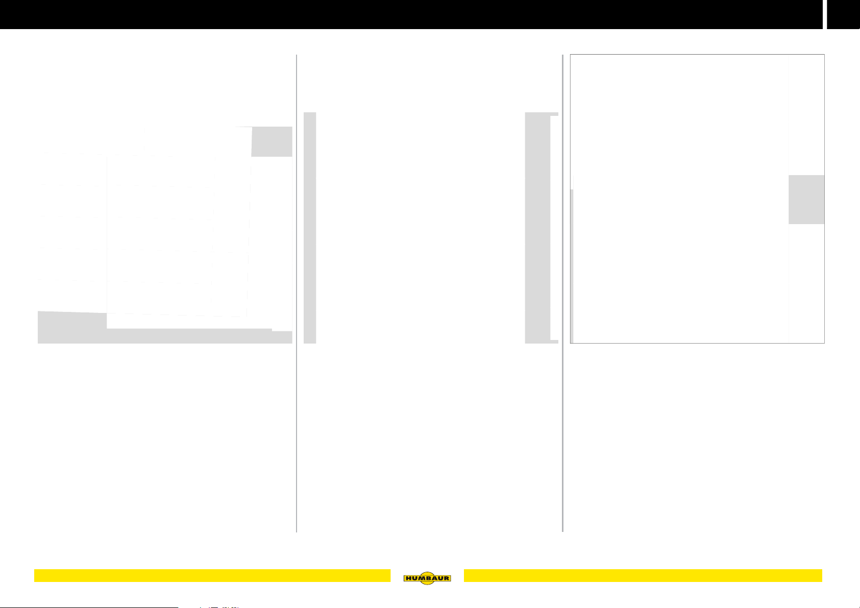
Colour combination
Design options
Safety accessories
Fig. 4 Colour choice - Maximus (examples)
The wide range of colours allows for individualisation of the
horse trailer. A number of colour combinations can be
selected for new Maximums models to provide even more
individuality.
Give your fantasies free rein with our 360° colour
configurator on the Humbaur website.
Fig. 5 Design variants - Maximus (examples)
Depending on your taste, the new Maximus provides a
selection of fender variants and tyre rims.
Fig. 6 Accessory options (examples)
Depending on the model, various components may be fitted
as accessories, e.g. safety clutch, access step, 3-brake
light, radio camera, etc.
13General information
Page 14
2
MACHT’S MÖGLICH
008
010
Product description
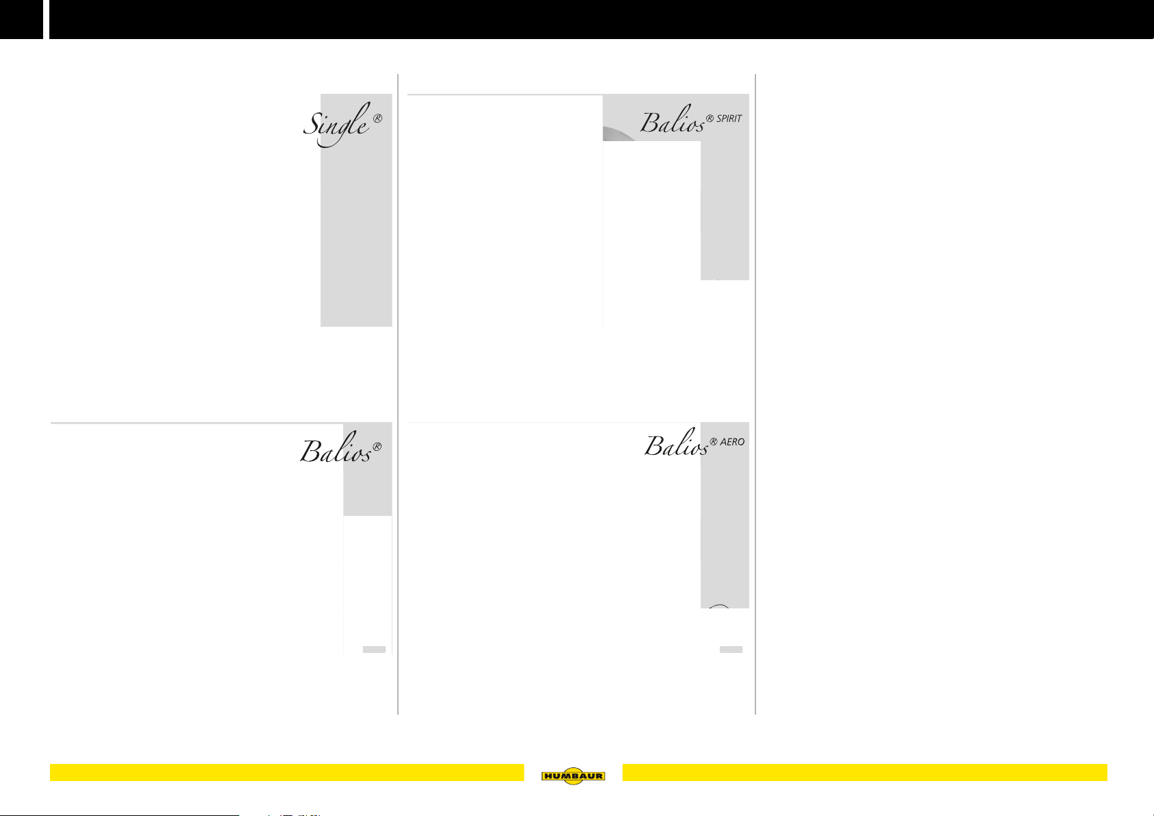
Model overview
Wood-polyester class
Fig. 7 Single
Full-length breast and breech bar
One-horse transport
with saddle compartment
Fig. 8 Balios
with deflector
with automatic support wheel
without saddle compartment
I - 007
I - 008I -
I - 009
Fig. 9 Balios SPIRIT
without deflector
without saddle compartment
I - 010I -
Fig. 10 Balios AERO
with deflector
with automatic support wheel
with saddle compartment
14 General information
Page 15
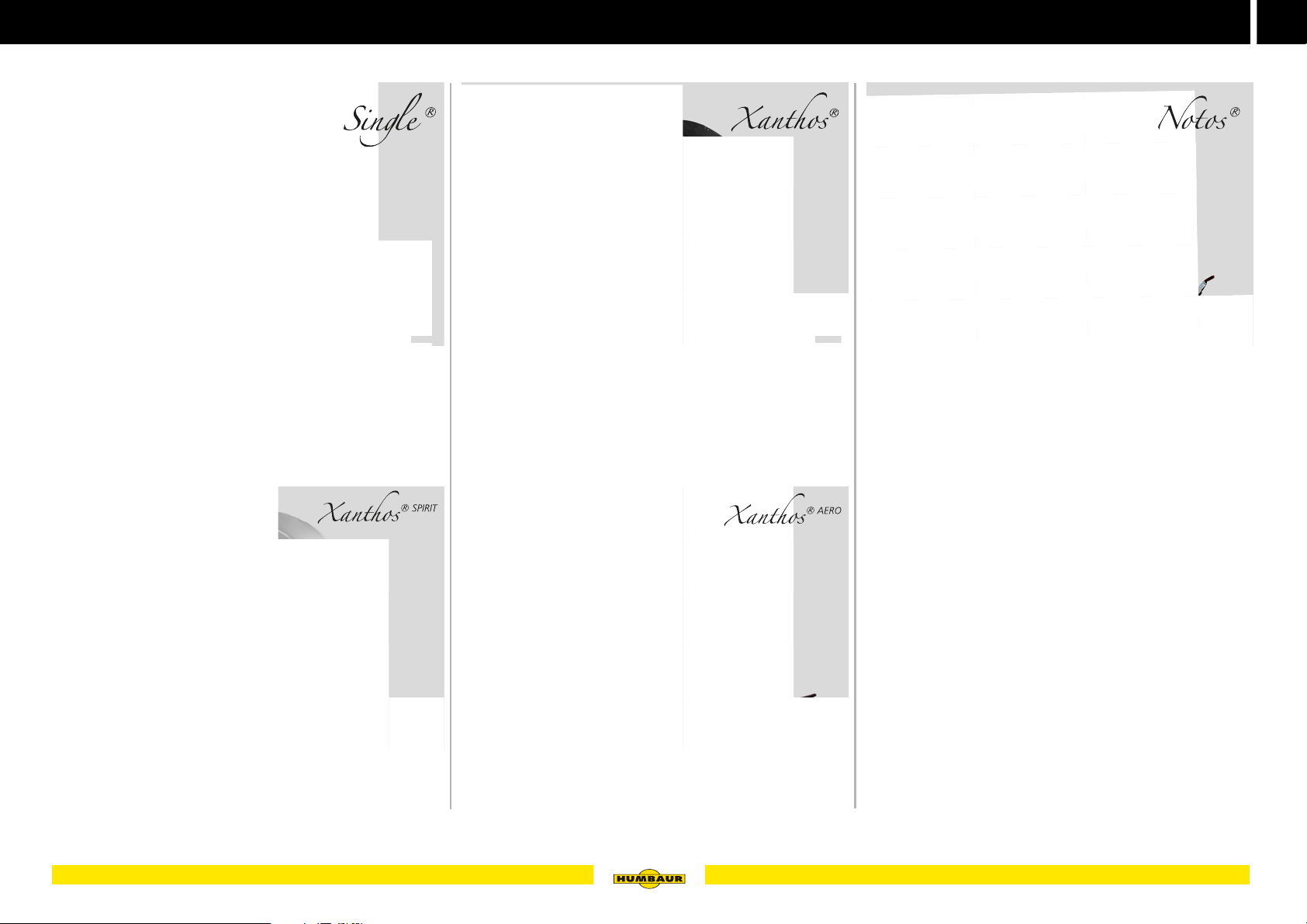
MACHT’S MÖGLICH
Aluminium-polyester class
Product description
2
Fig. 11 Single ALU
One-horse transport
Full-length breast and breech bar
with saddle compartment
with Windschott (deflector)
Fig. 12 Xanthos SPIRIT
without saddle compartment
without deflector
without wheel shock absorber (100 km/h)
I - 011I - 01
I - 012
Fig. 13 Xanthos
with AluBiComp floor
without saddle compartment
with deflector
with automatic support wheel
with wheel shock absorber (100 km/h)
Fig. 14 Xanthos AERO
with saddle compartment
with Windschott (deflector)
with wheel shock absorber (100 km/h)
I - 013I - 013
I - 014
I - 015
Fig. 15 Notos ALU
Rotating centre-post partition wall
Rotating hinge-mounted tailgate
Divided revolving / swivel front exit
with wheel shock absorber (100 km/h)
15General information
Page 16
2
MACHT’S MÖGLICH
8
PLUS
I
020
US
Product description
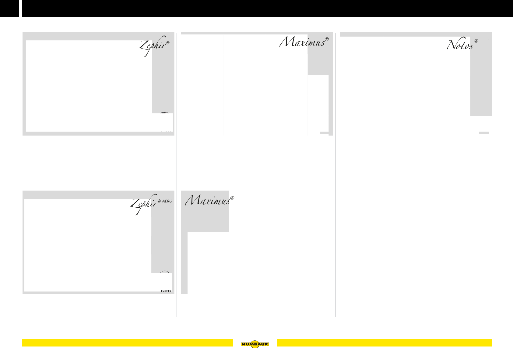
Full Polyester Class
Fig. 16 Zephir
with saddle compartment
with Windschott (deflector)
with automatic support wheel
with wheel shock absorber (100 km/h)
I - 016
Fig. 18 Maximus
with AluBiComp floor
Lateral kick protection made of aluminium
with saddle compartment
with Windschott (deflector)
with automatic support wheel
with wheel shock absorber (100 km/h)
I - 018I - 01
Larger vehicle class
Fig. 20 Notos PLUS
Tailgate rotates and swivels
Large saddle compartment cubicle
Passage door to saddle compartment cubicle (optional)
Access doors on both sides
with automatic support wheel
PL
I - 020
-
Fig. 17 Zephir AERO
with saddle compartment
with Windschott (deflector)
with automatic support wheel
16 General information
I - 017
I - 019
Fig. 19 Maximus Upgrade
with designer fenders
LED rear lights
Page 17
MACHT’S MÖGLICH
Carriage class
I - 023
I - 025
I
5
Product description
2
I - 021 I - 022
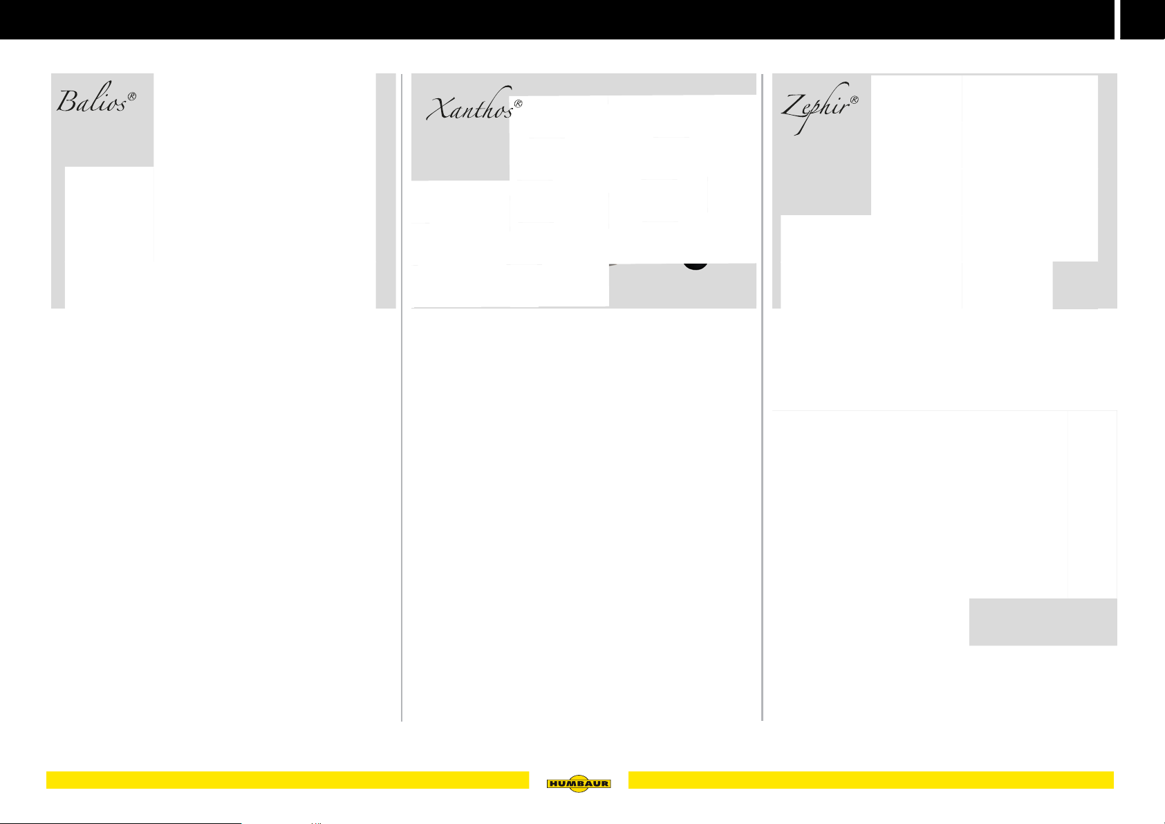
Fig. 21 Balios carriage
without deflector
without saddle compartment
– Aluminium loading ramps with lateral protective edge
– Aluminium stand rails with hot-dip galvanised stand
brackets
– with lashing rings for carriage retention
– with automatic support wheel
Fig. 22 Xanthos carriage
with deflector
without saddle compartment
with AluBiComp floor
Fig. 23 Two jockey wheels (optional)
for parking an unhitched trailer
I - 024
Fig. 24 Zephir carriage
with deflector
with saddle compartment
with wheel shock absorber (100 km/h)
- 02
Fig. 25 Carriage frame covered (optional)
Partition plate as cover
17General information
Page 18
2
MACHT’S MÖGLICH
11
12
13
18
29
14
27
17
16
15
I - 027
24
23
22
21
30
20
19
11
12
13
18
29
14
27
31
16
15
25
28
I - 029
24
23
22
21
30
20
26
11
18
32
14
27
16
15
25
28
29
24
23
22
21
30
20
26
I - 031
Product description
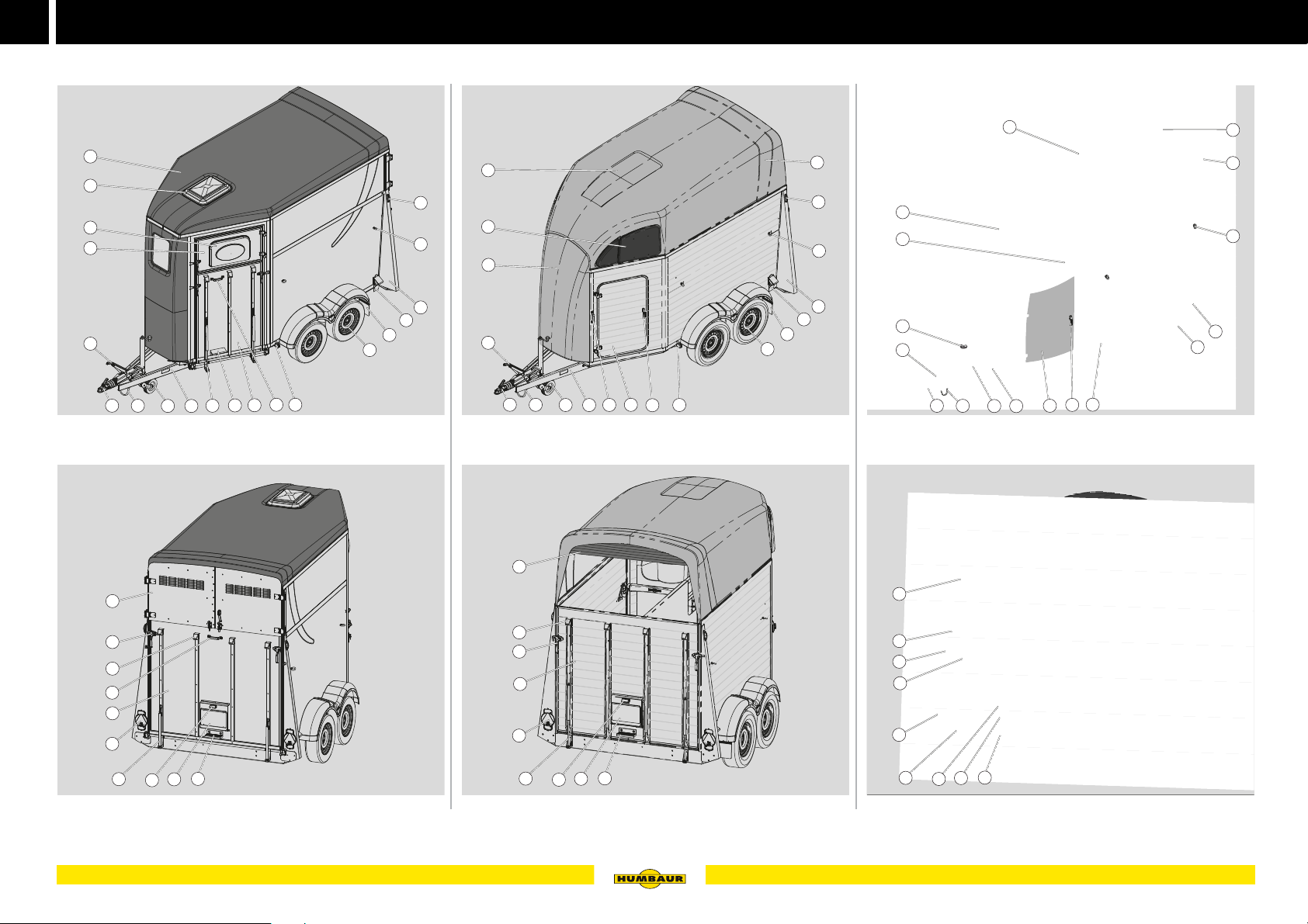
Components
8
10
10
10
1
2
3
Fig. 26 Notos - front / side view
Fig. 27 Notos - rear view
18 General information
8
5
4
I - 026
8 9
7
6
5
6
1
2
8
3
4
9
Fig. 28 Xanthos AERO - front / side view
5
6
Fig. 29 Xanthos AERO - rear view
I - 028
1
2
3
4
Fig. 30 Maximus - front / side view
5
6
Fig. 31 Maximus - rear view
9
I - 030
Page 19
Product description
MACHT’S MÖGLICH
I -
033
I - 034
I - 037
2
1 Ball coupling
2 Drawbar support
3 Jockey wheel
4 V drawbar
5 Gas strut
6 Step
7 Front access / exit / flap or revolving door
8 Handle
9 Front reflector / white reflector or
Front side light
10 Wheel (tyre)
11 Mud guards (with spray guards)
12 Wheel chock
13 Rear support
14 Tie-ring with panic locking
15 Roof vent
16 Vent window
17 Fold-out flap
18 Overrun hitch with hand brake lever, brake linkage, brake
accumulator
19 Rotary flap / windflap
20 Angle lever lock
21 Tailgate or revolving door
22 Tail lights
23 Number plate light
24 Registration number holder
25 Saddle compartment door
26 Deflector / roll-up tarpaulin
27 Rear side light
28 Rotary handle
29 Polyester hood (polyester, GFR)
30 Support surface
31 Front
32 Panorama roof (optional)
AluBiComp floor
Fig. 32 Floor with glued 8 mm rubber matting
Alloy wheel rim
Fig. 33 Bicolor alloy rims
Third brake light
I - 032
I - 033
LED rear lights
I - 035
Fig. 35 LED rear lights (Maximus)
Roof vent / skylight
I - 036
Fig. 36 on front section of roof
Spare wheel
Optional accessories
The following components can be optionally fitted.
Further versions can be constructed at customer request.
Fig. 34 at top rear
Fig. 37 at front of vehicle or to one side at the rear
19General information
Page 20
2
MACHT’S MÖGLICH
I - 040
I - 043
4
I - 046
Product description
Foal grid
Fig. 38 positioned on tailgate
Feeding trough
I - 038
Head partition
Fig. 41 positioned on partition
Manoeuvring handle
I - 041
Rubber tread strip
I - 044I - 04
Fig. 44 on the tailgate
Registration number holder
Fig. 39 for insertion
Stool
Fig. 40 loose stool as access aid
20 General information
I - 039
Fig. 42 positioned on the jockey wheel
Deflector
Fig. 43 Roll-up tarpaulin instead of roll-up net
I - 042
I - 045
Fig. 45 single or double line
Monitoring
Fig. 46 Radio camera with monitor in driver's cabin
Page 21

Product description
MACHT’S MÖGLICH
I - 049
I - 052
I - 055
2
Saddle compartment lighting
Fig. 47 LED light, battery-driven
Sliding window (Notos)
I - 047
Saddle compartment accessories
Fig. 50 Broom / shovel for cleaning trailer
Cleaning utensils
I - 050
Inside saddle support
I - 053
Fig. 53 Inside saddle rail, swivel-mounted
Outside saddle support
Fig. 48 Sliding window outside and inside
Power supply (Notos Plus)
Fig. 49 230V power supply / circuit breaker inside
I - 048
Fig. 51 Hoof scraper
Holders
Fig. 52 Snaffle holder / universal hook
I - 051
I - 054
Fig. 54 Outside saddle rail, fixed
Western saddle holder
Fig. 55 Western version
21General information
Page 22
2
MACHT’S MÖGLICH
I - 058
I - 061
062
I - 064
I
064
Product description
Side padding
Fig. 56 on right and left side
Side protection
I - 056
Wearing mat
Fig. 59 glued to the floor
Windflap
I - 059
Tailgate with revolving door function
I - 062I -
Fig. 62 Tailgate with revolving / swivel function
Saddle holder (Notos PLUS)
Fig. 57 as aluminium plate
Side protection
Fig. 58 as plastic plate
22 General information
I - 057
Fig. 60 GFR windflap at rear instead of deflector
Wheel shock absorber for 100 km / h
Fig. 61 RSD loose or installed
I - 060
I - 063
Fig. 63 Saddle holder rodding (foldable)
Step (Notos PLUS)
-
Fig. 64 Step to saddle compartment cubicle
Page 23

MACHT’S MÖGLICH
3
Operation
23
Page 24
3
MACHT’S MÖGLICH
PFERDETRANSPORT
620.00402
Safety first!
General safety information
Before setting off, make sure that the maximum
permissible loads (load capacity and drawbar load)
are not exceeded.
Take note of the safety information and instructions for load distribution in the operating instruction manual, “Trailers up to 3.5 to” General Points – Part 1".
Observe the maximum permissible towing load and
drawbar load of your towing vehicle and the trailer
coupling.
– Check the weight of the goods to be loaded where
required.
– Carry out a departure check (see operating instruction
manual, "Trailers up to 3.5 to" General Points - Part 1).
A warning sticker should be attached to the rear of
the trailer for safety reasons.
Prerequisites for safe driving with a trailer:
–The body must be fully closed while driving.
– The horse / horses must be secured with breast and
breech bars and tied up.
– Any other goods must be properly tied down/secured.
– The permissible gross weight and the axle loads must
be complied with.
– Comply with the load securing guidelines pursuant to
VDI 2700.
DANGER
Driving with unsecured tailgate / front exit
An unlocked tailgate / front exit may unintentionally fold
open while driving - accident risk!
The goods could fall out / the horse could panic - accident
risk!
Ensure that the tailgate / front flap is locked with the
angle lever locks before driving off. (The locking springs
on the angle lever locks must have latched).
WARNING
Climbing on the body
The body does not provide sufficient stability for
people.
The components of the body could give way or
break - Falling hazard!
Do not use the components of the body as a ladder.
Use a stable ladder for carrying out work on the body.
WARNING
Objects on the trailer!
Ice, snow, branches and other objects could fall
from the body / cargo bed while driving - risk of
accidents!
Before setting off, make sure that there are no pools of
water, Ice, snow, branches or other objects on the body
/ cargo bed.
Remove these if required.
Use a stable ladder where required.
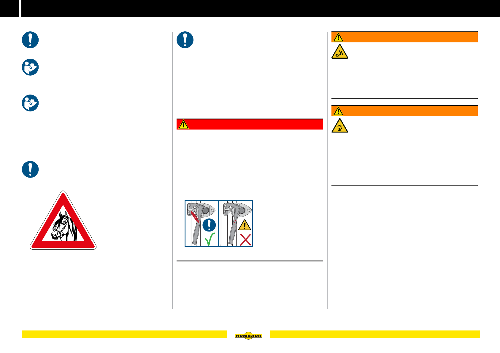
– Always remember:
You are transporting "LIVE ANIMALS"
- which could panic!
24 Operation
Immediately replace missing / defective locking springs.
Page 25
Safety first!
MACHT’S MÖGLICH
B - 001
B - 003
3
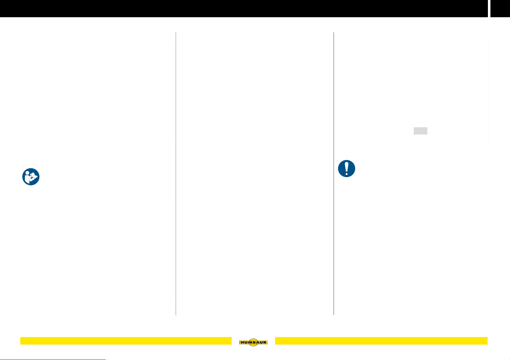
Driving in a car and trailer combination with horses
Fig. 1 Driving in car and trailer combinations (example image)
Take note of the safety / driving instructions for
driving with the towing vehicle and trailer stated in
the operating instruction manual
"Trailers up to 3.5 to" - General - Part 1.
Driving at 100 km / h
Carry out a departure check
(see operating instruction manual, “Trailers up to 3.5 to”
(General Points - Part 1).
Drive particularly carefully when transporting horses and
look ahead.
Adapt your driving style to the road and
weather conditions!
Reduce your speed and drive particularly carefully
around bends and when turning!
Start braking processes smoothly (not suddenly)
Stop immediately if the horse starts to jump around in the
trailer.
Fig. 3 Maximum speed / 100 km / h sticker
Your trailer can be licensed for a top speed of
100 km / h.
For this, several conditions must be fulfilled.
- For information, see www.humbaur.com / Interesting facts
Fig. 2 Driving in car and trailer combinations (example image)
Have any missing wheel shock absorbers retrofitted to
the trailer.
B - 002
25Operation
Page 26
3
MACHT’S MÖGLICH
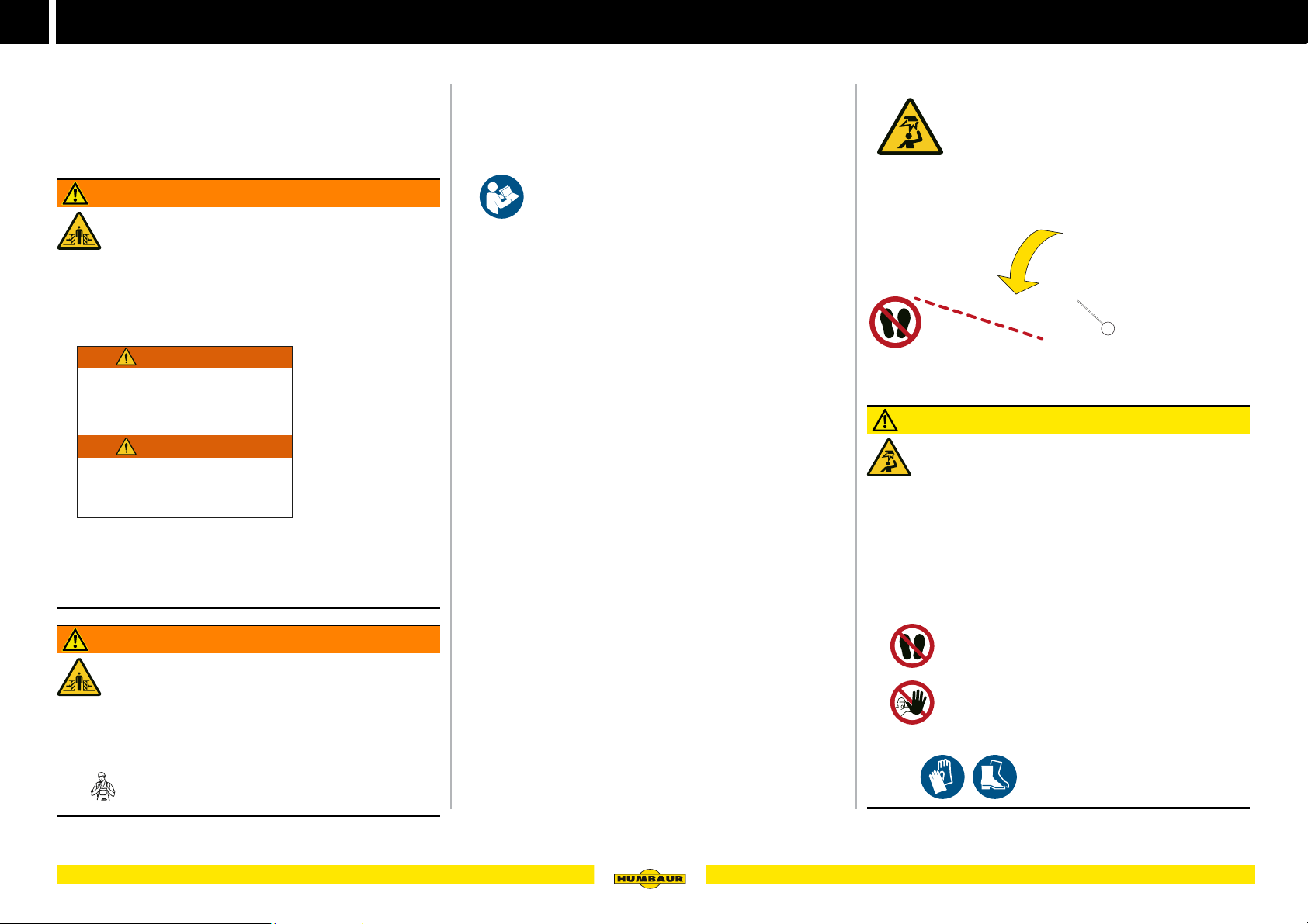
WARNING
The HORSE could crush you to death !
X
Open the front ap / door
before loading the horse
- RISK OF ESCAPE!
WARNING
You can be crushed by Horse !
X
Open the front door before
loading the horse
- ESCAPE !
620.00436
Loading and unloading
Preparation
– Make sure that road traffic safety is not impaired when
loading and unloading the trailer.
– If necessary, use additional signalling devices, e.g.,
signs, barriers.
WARNING
The horse may panic
There is no escape route if the access door / front
exit is locked - risk of crushing / impact!
Ensure that the access door / front exit is unlocked and
opened before guiding in the horse.
Pay attention to the warning note:
Train entering and exiting with your horse several times
as required.
Familiarise your horse with the trailer and the noises
made to reduce the stress.
Procedure:
Park the trailer on a firm surface to prevent it from sinking
in or tipping over.
First, couple the trailer to the towing vehicle, then operate
the parking brake of the towing vehicle.
Observe the safety instructions for manipulating
the wheel chocks in the operating instruction
manual, “Trailers up to 3.5 to – General - Part 1.”
In addition, secure the trailer against rolling by using the
wheel chocks.
Operating the tailgate
1
B - 004
Fig. 4 Operating the tailgate
1 Tailgate folded down
CAUTION
Tailgate falling down
After unlocking, the tailgate can fold open or fold
down in an uncontrolled manner - impact / crushing
risk!
People's hands/ feet may be crushed.
Stand to the side when unlocking the tailgate.
Hold the tailgate with one hand at the side.
If the gas struts are faulty, allow the tailgate to fall to the
floor - do not try to catch it.
Restricted view
People may not be seen and be run over when
reversing.
Use the mirrors to correctly assess the danger area
around the vehicle.
Have someone guide you when reversing.
26 Operation
WARNING
Keep your feet out of the danger area.
Keep people out of the danger area when folding
down the tailgate.
Use , .
Page 27
MACHT’S MÖGLICH
Loading / moving in the horse
B - 005
B - 007
kg
Loading and unloading
3
1
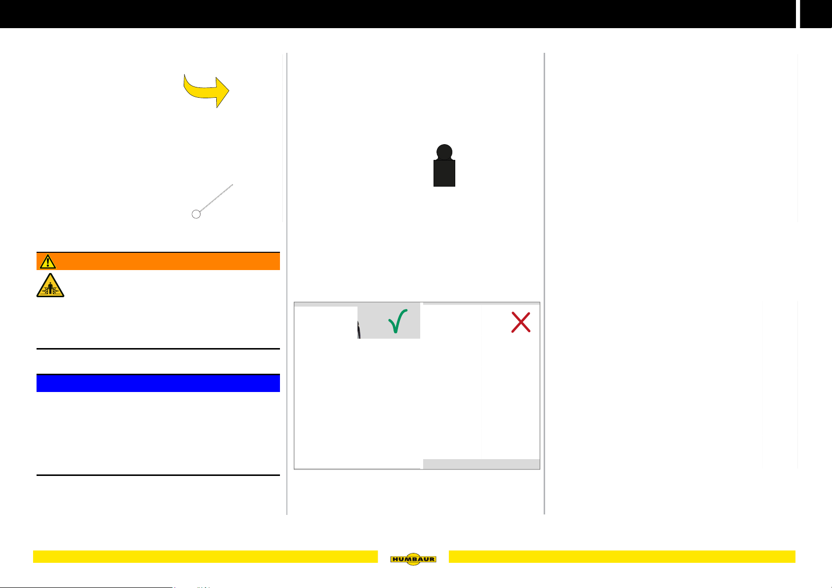
Fig. 5 Access door CLOSED / OPEN
WARNING
The horse may panic!
There is no escape route if the access door / front
exit is locked.
The horse may crush you to death / squash you.
Before leading in the horse, check that the
access door / front exit is unlocked and open.
NOTICE
Overloading the tailgate / front exit!
The tailgate / front exit can be deformed. The maximum
permissible drawbar load is exceeded.
Load the tailgate / front exit evenly.
Only move in one horse at a time.
Avoid point loads.
Fig. 6 Maximum load on the tailgate
Unlocking the breech bar.
Swivel it downwards.
Check that the breast bar is attached and secured.
Fig. 7 Position the horse
B - 006
B - 008
Fig. 8 Guiding in the horse
Slowly and carefully walk over the tailgate and lead up
your horse slowly and in a controlled manner.
B - 009
Fig. 9 Securing a horse
Position the horse in line with the tailgate.
Tie the horse to an internal eyelet.
Attach the breech bar and secure it.
27Operation
Page 28
3
MACHT’S MÖGLICH
Load securing / load distribution
Positioning horses in the trailer
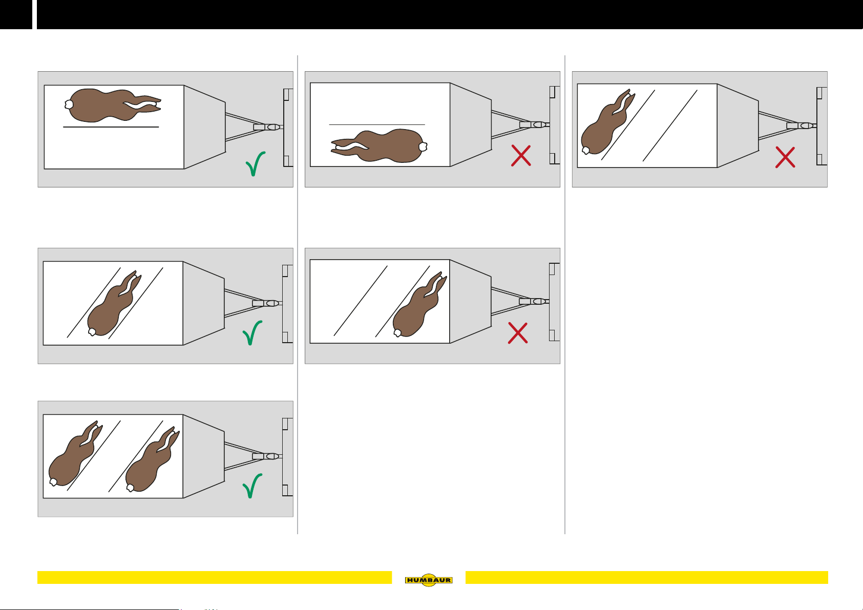
Correct load distribution
Incorrect load distribution
Fig. 10 Two-horse trailer with one horse
The horse is positioned on the left side.
Fig. 11 Three-horse trailer with one horse
The horse is positioned in the middle.
B - 010
B - 011
B - 013
Fig. 13 Two-horse trailer with one horse
The horse is positioned on the right side / head facing
backwards. The trailer may tilt when driving over unfortified
road edges.
B - 014
Fig. 14 Three-horse trailer with one horse - front
The front axle on the trailer and the rear axle of the towing
vehicle are excessively loaded. Drawbar load too high overloading!
B - 015
Fig. 15 Three-horse trailer with one horse - rear
The trailer tilts backwards; the towing vehicle tilts forwards
= the drawbar load is too low or is negative.
The rear axle on the trailer and the front axle of the towing
vehicle are excessively loaded.
Fig. 12 Three-horse trailer with two horses
The horses are positioned at the back and front.
28 Operation
B - 012
Page 29
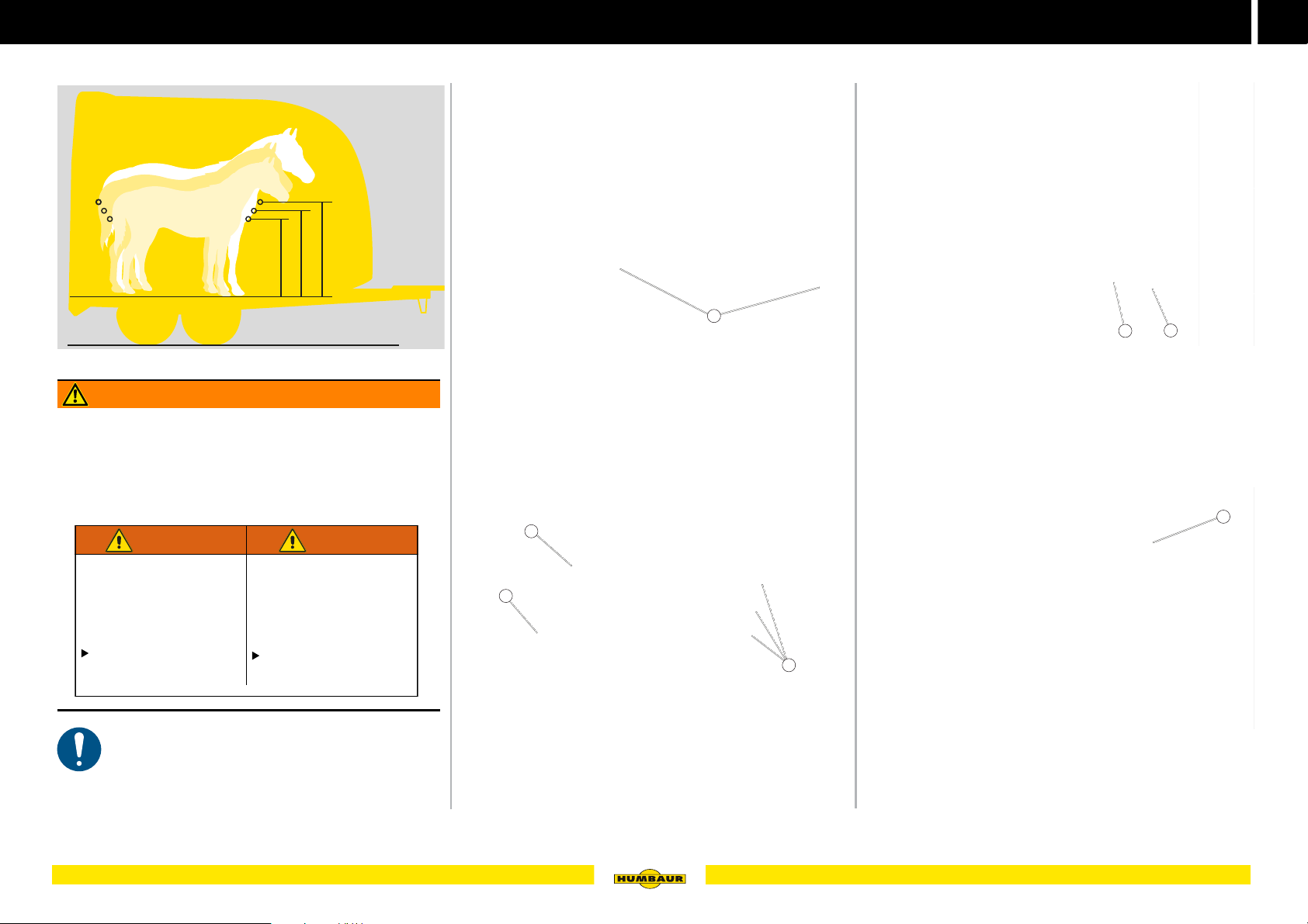
Load securing / load distribution
MACHT’S MÖGLICH
mm
mm
mm
944
994
1044
Unsecured breast /
breech bars!
Loose breast / breech bars!
F
t
transfer by horse / danger of
skidding.
Engage and secure the
breast / breech bars before
driving.
620.00275
WARNING WARNING
Bars may fall down while driving
and the weight distribution of the
horse may change / risk of skidding.
Suspend and secure the
breast / breech bar
before driving o.
3
Securing a horse
B - 016
Fig. 16 Breast and breech bars - height adjustment
WARNING
Unsecured horse
The horse can make the trailer lurch by changing the weight
distribution during the drive - accident risk!
Check that the horse is / horses are secured with breech
/ breast bars.
Fig. 17 Lashing options
1 Eyelets
1
Securing the breast / breech bar
1
B - 017
Fig. 19 Breast bar secured / horse tied up
1 Breast bar, secured
2 Eyelet
2
1
B - 019
Engage the breast bar (Fig. 19 /1) - see page 74.
Tie the horse to the rail (Fig. 19 /2).
1
alling bars while driving - weigh
The breast and breech bar holder can be set to 3
height levels.
The breast and breech bars must be positioned in
accordance with the size of your horse.
2
3
B - 020
B - 018
Fig. 18 Breast and breech bars
1 Breast bar
2 Breech bar
3 Eyelets at 3 heights
Fig. 20 Breech bar - horse secured
1 Breech bar, secured
Engage the breech bar (Fig. 20 /1) - see page 74.
29Operation
Page 30
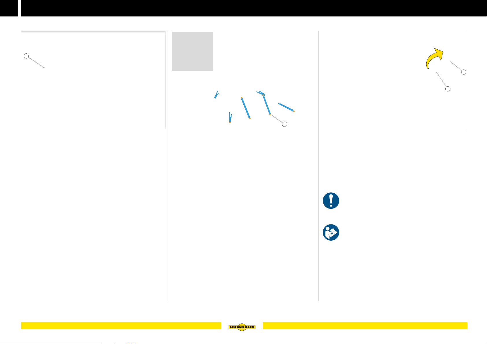
3
MACHT’S MÖGLICH
Load securing / load distribution
Securing a foal during transport
1
Fig. 21 Safeguard against jumping out
1 Foal grid
Fold up the foal grid (Fig. 21 /1) and secure it - see
page 60.
B - 021
Securing a carriage
Fig. 22 Carriage secured
1 Tie-down points
Tie down the carriage at the lashing points
(Fig. 22 /1) - see page 39.
Tie-down points (optional)
1
2
1
B - 022
B - 023
Fig. 23 Tie-down points (optional)
1 Tie-down bracket (400 daN, kg)
2 Cargo bed
3 Groove
The retractable tie-down brackets finish flush with the cargo
bed (Fig. 23 /2).
The tie-down points are used to tie down solid goods.
Adhere to the maximum tie-down forces of 400 daN
/ kg.
30 Operation
Take note of the safety information for load
securing in the operating instruction manual,
“Trailers up to 3.5 to” General Points – Part 1".
Slowly slide the tie-down bracket (Fig. 23 /1) upwards
and out of the groove (Fig. 23 /3).
Fold any tie-down points not required back into the
groove.
Page 31
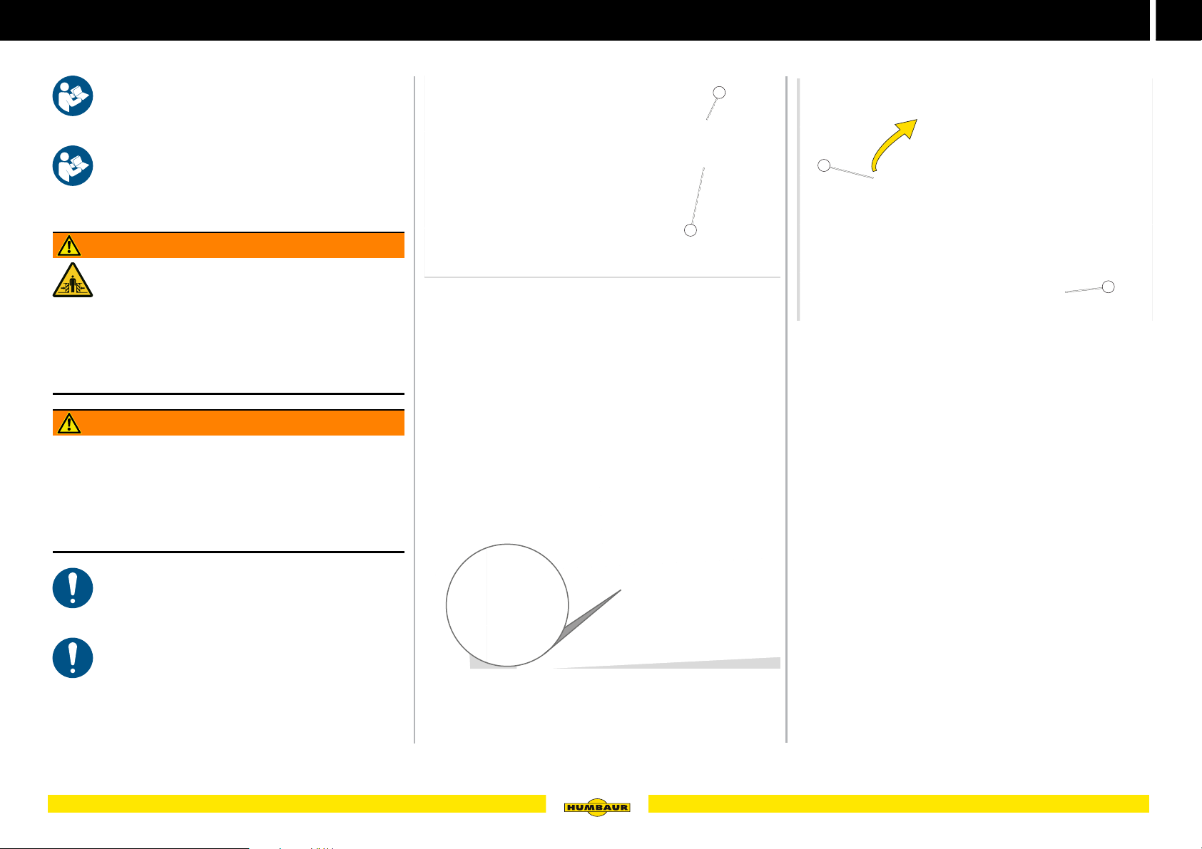
Uncoupling / Parking
MACHT’S MÖGLICH
B - 024
B - 025
3
Securing the trailer against rolling
Take note of the instructions for the uncoupling
process in the operating instruction manual,
“Trailers up to 3.5 to” General Points – Part 1".
Observe the general safety and warning
instructions on safely parking your trailer in the
operating instruction manual “Trailers up to 3.5 to”
(General Points – Part 1).
WARNING
Incorrectly uncoupled trailer
The trailer could start moving and tip over.
People could be struck by the trailer and run over -
risk of crushing!
Only uncouple the trailer when it is empty.
Use wheel chocks and the hand brake to secure the
trailer from rolling away before uncoupling.
WARNING
Unsecured wheel chocks
Unsecured wheel chocks could fall off while driving - risk of
accidents!
Check that the wheel chocks are secured before driving
off.
Check the holders for damage at regular intervals.
2
1
Fig. 24 Example of Zephir - position of wheel chocks
1 Wheel chock
2 Holder
The position of the wheel chocks may vary for the various
horse trailer models:
– for wood and alu-poly models:
at the rear behind the fender
Engaging the hand brake
1
2
B - 026
Fig. 26 Activating the hand brake
1 Hand brake (engaged)
2 Jockey wheel (in parking position)
Wind down the jockey wheel (Fig. 26 /2) until it reaches
the floor.
Completely pull up the hand brake (Fig. 26 /1).
In addition to the parking brake, the trailer must be
secured with wheel chocks on slopes / gradients
and when uncoupled.
Wheel chocks must always be available. Replace
any lost or damaged wheel chocks immediately.
Fig. 25 Example of Maximus - position of wheel chocks
– for full-poly models:
in the front section of the chassis below the body
31Operation
Page 32
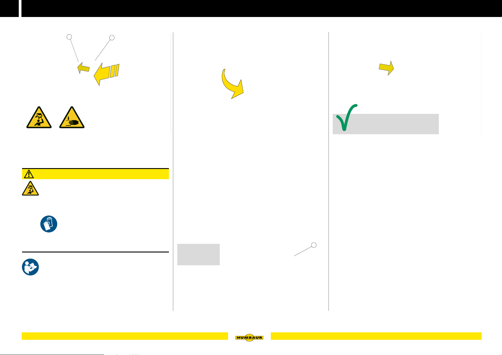
3
MACHT’S MÖGLICH
Uncoupling / Parking
Manipulating the wheel chocks
1
Fig. 27 Releasing the wheel chock
1 Lever
2 Wheel chock
CAUTION
Removing the wheel chocks
You could crush your hands / fingers when
removing the wheel chocks. You could also hit your
head on the chassis / body.
2
B - 027
Fig. 28 Removing the wheel chock
Remove the wheel chock from the holder.
B - 028
B - 030
Fig. 30 Secure the wheel chock (driving position)
Position the wheel chock in the holder - the grooves must
be aligned with the lugs.
Slide the wheel chock into the holder until it engages - a
clicking noise can be heard.
The wheel chocks have been secured in the holders on
both sides.
Use .
Operate the wheel chocks slowly and carefully.
Avoid jerky movements.
Observe the safety instructions for manipulating
the wheel chocks in the operating instruction
manual, “Trailers up to 3.5 to – General - Part 1.”
Press the lever into the holder (Fig. 27 /1).
Slide out the wheel chock (Fig. 27 /2) at the same time.
32 Operation
1
B - 029
Fig. 29 Wheel chocks positioned
1 Wheel chock
Place the complete surface of the wheel chocks
(Fig. 29 /1) under the wheels.
Consider the direction of inclination of the trailer e.g. on
a slope.
Page 33
Uncoupling / Parking
MACHT’S MÖGLICH
B
B - 034
3
Manoeuvring
1
2
Fig. 31 Manoeuvring option (Maximus model)
1 Manoeuvring handle
2 Jockey wheel
The trailer may only be manouevered when it is
empty.
Preparation:
Lower the jockey wheel (Fig. 31 /2).
Close the tailgate / front exit / access door / saddle
compartment.
Release the handbrake.
B - 031
1
2
Fig. 32 Manual manoeuvring of the trailer
1 Handle (in front)
2 Jockey wheel
B - 032
For manual manoeuvring, use the handle (Fig. 31 /1) on
the jockey wheel or the handles (Fig. 32 /1) at the front of
the trailer.
Pull / push the trailer in the desired direction.
Ensure that your feet do not get under the jockey wheel
(Fig. 32 /2).
Use .
Parking with a horse
B - 033
Fig. 33 Parked trailer with horse
Uncoupling of a loaded trailer (with horse) is not
permitted.
Open the tailgate / access door / deflector / vent window
or ventilation flaps.
Fig. 34 Trailer coupled / horse tied-up outside
Tie up the horse, e.g. at the outer eyelets or at the saddle
support.
33Operation
Page 34

3
MACHT’S MÖGLICH
B - 035
B - 036
Provide for the horse
Radio monitoring
1
Fig. 35 Monitor in the towing vehicle
1 Radio monitor
Monitoring the horse in the trailer increases safety and
provides an indication if the horse panics so that action can
be taken in good time.
1
Saddle support
Fig. 37 External saddle support (rigid)
The saddle may not be transported on the saddle
support rail while driving.
A saddle support rail can be optionally installed on the
outside wall.
Hoof scraper
1
2
B - 037
B - 039
Fig. 39 Hoof scraper
1 Saddle compartment
2 Hook
3 Hoof scraper
4 Storage net
The hoof scraper is used to clean horses' hooves.
It can also be used as a tool for emergency unlocking from
the outside.
Stow the hoof scraper (Fig. 39 /3) inside the trailer, e.g.
in the saddle compartment (Fig. 39 /1), in the storage net
(Fig. 39 /4) or on a hook (Fig. 39 /2).
Fig. 36 Camera in the trailer
1 Camera
Have a radio monitoring system installed by a specialist
workshop.
34 Operation
B - 038
Fig. 38 Inner storage bracket (swivel-mounted)
Several swivel-mounted storage brackets can be attached
to the inside of the trailer (e.g. for Notos Plus).
Page 35

Provide for the horse
MACHT’S MÖGLICH
B - 044
3
Feeding trough / storage shelf
1
Fig. 40 Storage shelf on the saddle compartment
1 Feeding trough
Depending on the accessories, the storage shelf in the
saddle compartment may be deeper and used for the
storage of horse blankets or horse feed, e.g. hay.
B - 040
Feeding trough
B - 042
Fig. 42 Feeding troughs inserted
The feeding troughs are used as food and water containers.
2
1
B - 043
Fig. 43 Insert the feeding troughs
1 Metal lugs
2 Eyelet
Hay net
1
2
B - 045
Fig. 45 Hay net hung up
1 Eyelet
2 Hay net
The hay net (Fig. 45 /2) is attached to the eyelet (Fig. 45 /1)
in the ceiling.
Use an access aid to attach the hay net, e.g. stool.
1
Fig. 41 Storage shelf with rail
1 Rail
A rail in the saddle compartment is used as separator for
stored materials such as cooler blankets.
Only store light materials on the storage shelf.
Tie them to the rail (Fig. 41 /1) as required.
Insert the metal lugs of the feeding trough
(Fig. 43 /1) into the eyelets (Fig. 43 /2).
1
B - 041
Fig. 44 Feeding troughs stacked when not in use
1 Front holder
Stack the empty feeding troughs and insert them into the
holders (Fig. 44 /1).
35Operation
Page 36

3
MACHT’S MÖGLICH
Provide for the horse
36 Operation
Page 37

MACHT’S MÖGLICH
4
Operating the chassis
37
Page 38
4
MACHT’S MÖGLICH
Step (accessories)
Step (Notos PLUS)
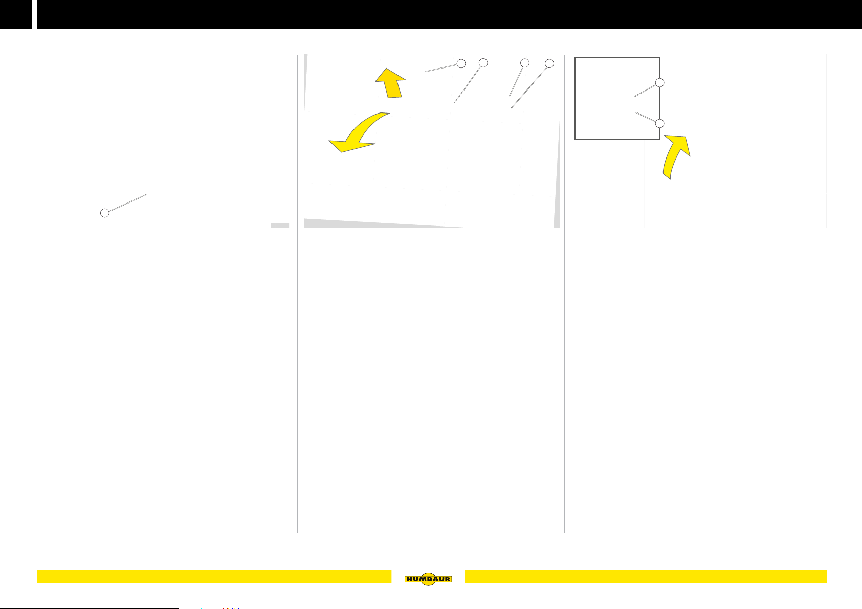
1
Fig. 1 Step
1 Step
An optional step (Fig. 1 /1) allows for more comfortable
access to the saddle compartment cabin of the Notos
PLUS.
F - 001F - 001
Folding out the step
Fig. 2 Folding out the step
1 Handle
2 Step
3 Bolt
4 Locking mechanism
2
1
3
F - 002
Pull the step (Fig. 2 /2) handle (Fig. 2 /1) upwards until
the bolt (Fig. 2 /3) is released from the lock (Fig. 2 /4).
Fold the step downwards.
Folding in the step
4
1
2
F - 003
Fig. 3 Folding in the step
1 Bolt
2 Locking mechanism
Fold the step upwards.
Push the stop downwards, using the handle,
until the bolt engages.
38 Operating the chassis
Page 39
MACHT’S MÖGLICH
Carriage frame
3
S
kg
DANGER
Transporting a carriage when the trailer is not loaded
The drawbar load is exceeded and the trailer may start to
lurch - accident risk!
Only transport a carriage when the trailer is loaded
(horse) - weight compensation.
Take note of the stickers attached.
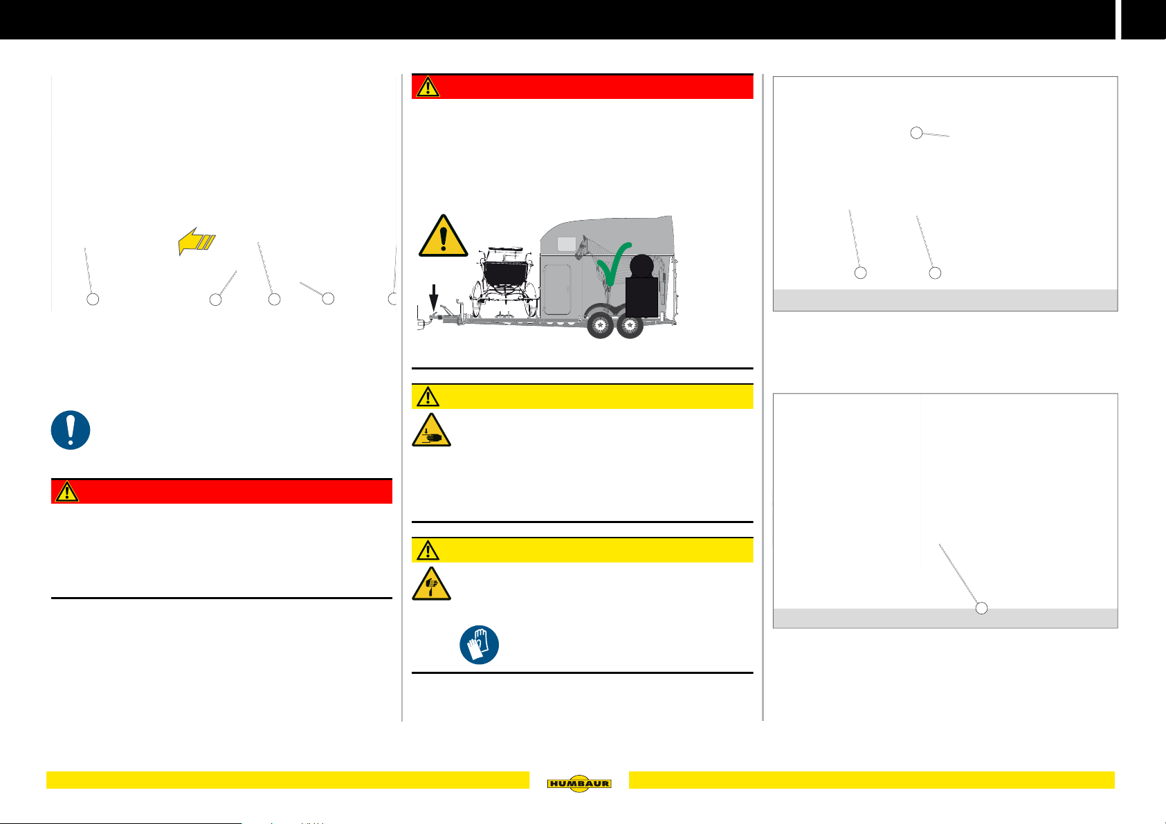
Carriage frame
1
4
7
Fig. 4 Example Xanthos - carriage frame
The carriage frame is only designed for the transport of
carriages.
Transport of other goods is not permitted.
Carriage transport may only be performed within
the framework of the permissible gross weight and
adherence to the max. drawbar load.
6
5
4
DANGER
Driving with unsecured loading ramps
Unsecured loading ramps may unintentionally come loose
while driving and fall off the frame - accident risk!
Check that the loading ramps are secured before driving
off.
kg
Comply with the drawbar load.
CAUTION
Operating loading ramps
Fingers / hands can be injured when removing and
positioning the loading ramps.
Remove and position the loading ramps carefully.
Hold them at the sides.
Keep your fingers / hands away from the crush area.
CAUTION
Sharp edges
Fingers / hands can be cut on sharp edges when
removing and positioning the loading ramps.
Use .
2
Fig. 5 Carriage frame (Version 1)
1 Carriage wheel stop
2 Loading ramp holder
3 Stand rails
Fig. 6 Carriage frame (Version 2)
1 Carriage frame with tread plate
3
F - 005
1
F - 006
39Operating the chassis
Page 40
4
MACHT’S MÖGLICH
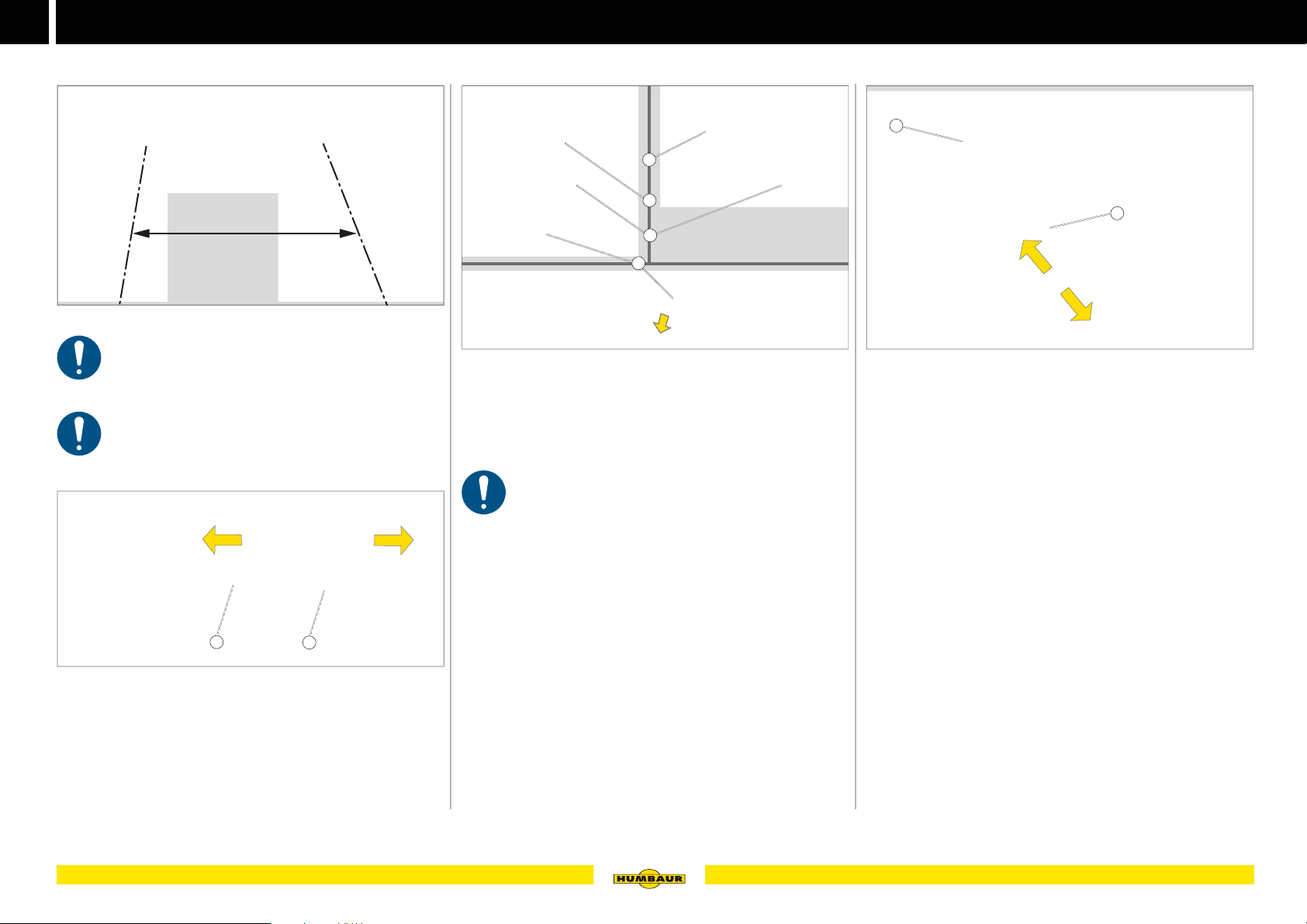
min. 863 mm
max. 1367 mm
Carriage frame
Setting the track width
Fig. 7 Permissible track width
The permissible track width is between 863 mm
and 1367 mm.
The stand rails must be placed onto the drawbar
centrally.
1
Fig. 8 Shifting the stand rail
1 Screw connection
2 Stand rail
Attaching the loading ramps
1
2
3
4
F - 007
F - 009
Fig. 9 Attaching the loading ramp
1 Stand rail
2 Securing bolt with cotter pin
3 Loading ramp
4 Lug
The loading ramps must safely rest / connect to the
stand rail.
Loading the carriage
1
2
F - 010
Fig. 10 Set the carriage wheel stop
1 Carriage wheel stop
2 Screw connection
Loosen the screw connection (Fig. 10 /2) of the carriage
wheel stop.
Push the carriage wheel stop (Fig. 10 /1) in the direction
required.
Release the cotter pin from the safety bolt (Fig. 9 /2).
Remove the loading ramps (Fig. 9 /3).
Adjust the carriage wheel stops to the carriage size
required.
Secure the screw connection.
Push the pins (Fig. 9 /4) of the loading ramp into the
insertion holes of the stand rail (Fig. 9 /1).
2
F - 008
Release the screw connection (Fig. 8 /1) of the stand rail
and shift the rail into the desired direction.
Position the stand rails (Fig. 8 /2) to the track width of the
carriage to be loaded.
Secure the screw connection.
40 Operating the chassis
Page 41
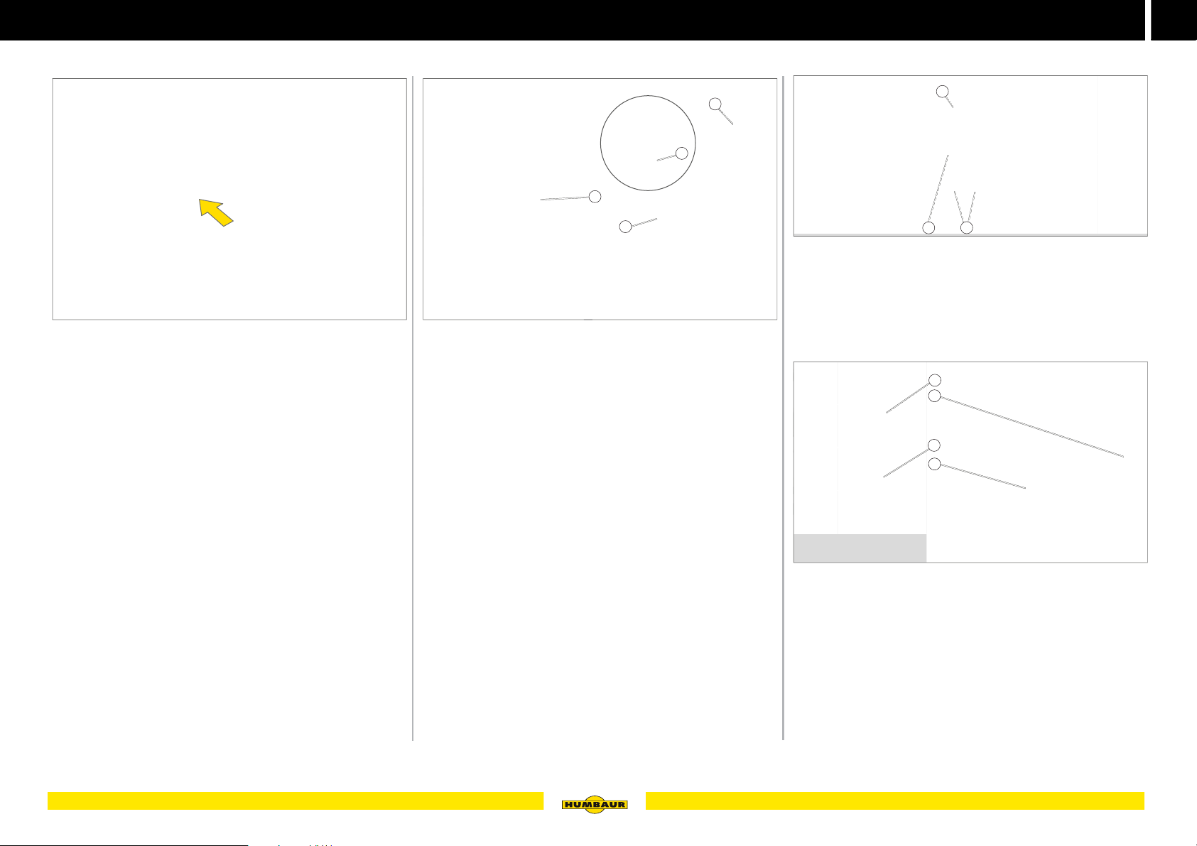
Carriage frame
MACHT’S MÖGLICH
4
Driving on the loading ramps
Fig. 11 Driving on the loading ramps
Carefully push the carriage onto the carriage frame.
Securing the loading ramps
3
4
1
2
F - 011 F - 012
Fig. 12 Securing the loading ramps (Version 1)
1 Loading ramp holder
2 Loading ramps
3 Elastic cord fastener
4 Hook
Position the loading ramps (Fig. 12 /2) in the loading
ramp bracket (Fig. 12 /1).
Tighten the elastic cord fasteners (Fig. 12 /3) over the
loading ramps and secure them on the
hooks (Fig. 12 /4).
1
3
2
Fig. 13 Securing the loading ramps (Version 2)
1 Loading ramp holder
2 Safety device (cotter pin)
3 Loading ramp
Position the loading ramps (Fig. 13 /3) in the loading
ramp bracket (Fig. 13 /1).
1
2
3
4
F - 013
F - 014
Fig. 14 Securing the loading ramps (Version 2)
1 Loading ramp holder
2 R-clip
3 Threaded bolt
4 Loading ramp
The threaded bolt (Fig. 14 /3) must pass through the hole
in the loading ramp (Fig. 14 /4).
Insert the cotter pin (Fig. 14 /2) into the hole in the
threaded bolt.
The loading ramps are secured against falling down
while driving.
41Operating the chassis
Page 42

4
MACHT’S MÖGLICH
Carriage frame
42 Operating the chassis
Page 43

MACHT’S MÖGLICH
5
Operating the body
43
Page 44
5
MACHT’S MÖGLICH
Door handles / angle lever locks
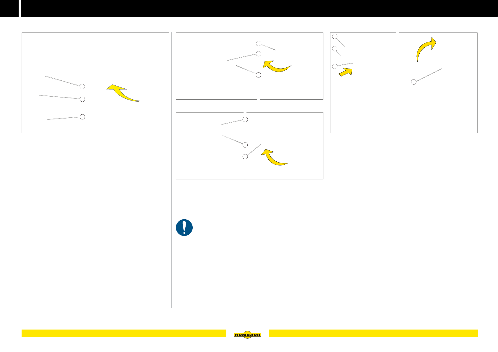
Operating the door handle (outside)
1
2
3
Fig. 1 Door handle closed / open
1 Cylinder lock
2 Key (in duplicate)
3 Rotary lever
The door handles are integrated into the saddle
compartment door / access door and flaps. The door
handles are lockable.
Unlock the door handle
Unlock the cylinder lock (Fig. 1 /1) with the
key (Fig. 1 /2).
Turn the rotary lever by 90° to horizontal position.
The door / flap can be opened.
Locking the door handle
Close the door / flap.
Turn the rotary lever by 90° to vertical position.
Lock the cylinder lock with a key as required.
The door / flap is now locked.
Keep the key in a safe place.
A - 001
Operating the rotary knob / handle (inside)
1
2
3
Fig. 2 Rotary knob closed / open
2
3
4
Fig. 3 Rotary handle closed / open
1 Rotary knob
2 Closing bracket
3 Lock slide
4 Rotary handle
The cylinder lock of the access door must be
unlocked!
Opening
Turn the rotary knob (Fig. 2 /1) or rotary handle
(Fig. 3 /4) by 90°.
The closing bracket (Fig. 2 /2) moves out.
Closing
Pull the access door closed.
Turn the rotary knob / handle by 90°.
The closing bracket locks into the lock slide (Fig. 2 /3).
The access door is now locked from the inside.
Operating the angle lever lock
1
2
3
4
A - 002
A - 004
Fig. 4 Angle lever lock closed / open
1 Hook
2 Eyelet
3 Locking spring
4 Lever
A - 003
Unlocking
Push in the locking spring (Fig. 4 /3) while at the same
time turning the lever (Fig. 4 /4) upwards into vertical
position.
The hook (Fig. 4 /1) is released from the eye (Fig. 4 /2).
The angle lever lock is unlocked.
Locking
Turn the lever until it is completely closed and the locking
spring latches.
The angle lever lock is secured by the locking spring.
44 Operating the body
Page 45
Door holder
MACHT’S MÖGLICH
5
Operating the door holder
1
2
43
Door holder to press in / snap in
2
Fig. 6 Press-in door holder
1 Nipple
2 Bush
Door holder for hooking-in
1
A - 006
Fig. 7 Door holder secured
1 Locking lever
2 Locking sleeve
1
2
A - 007
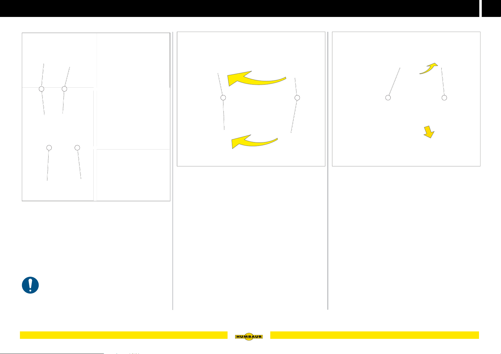
Fig. 5 Door holder overview
1 Nipple (for pressing in or latching)
2 Bush
3 Holding lever (to hook in)
4 Locking sleeve
The door holder secures the access door / saddle
compartment door / flaps against autonomous falling shut.
The mechanisms vary between pressing-in, latching or
hooking-in, depending on the model.
The access door / saddle compartment door / flaps
must be secured with a door holder against falling
shut.
The doors / flaps must also be held by hand when the wind
is strong!
A - 005
Locking
Press the door / flap towards the body until the nipple
(Fig. 6 /1) has latched in the socket (Fig. 6 /2).
Releasing
Pull on the door / flap with some force.
The door holder unlatches from the lock.
The door / flap can be closed.
Locking
Swivel the locking lever (Fig. 7 /1) towards the locking
sleeve (Fig. 7 /2).
Guide the locking lever into the locking sleeve.
Press the locking lever inwards and up to the limit stop.
Unlocking
Pull the locking lever towards yourself.
Slide the locking lever out of the locking sleeve.
Release the locking lever.
The door / flap can be closed.
45Operating the body
Page 46
5
MACHT’S MÖGLICH
Saddle compartment
Saddle compartment accessories
5
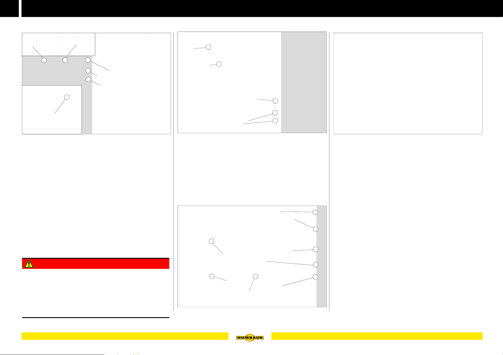
Fig. 8 Example Xanthos AERO internal view.
1 Mirror, glued on
2 Revolving door
3 Rotary knob, 3-point locking
4 Drainage hole (in the floor)
5 Fastening bracket
6 Gas strut
6
4
The saddle compartment is used as a storage area for
horse accessories:
– Saddle
–Bridle
– Broom and shovel
Additional accessories can be transported in the saddle
compartment. The saddle compartment has holes in the
floor for water drainage.
1
2
3
A - 008
DANGER
Driving with an unlocked saddle compartment door.
An unlocked saddle compartment door may autonomously
fold open while driving - accident risk!
The goods might fall out - impact risk!
Make sure that the saddle compartment door is closed
and secured before driving off.
1
2
3
4
5
Fig. 9 Example Notos ALU, internal view
1 Lights
2 Saddle holder (fixed / optionally equipped for swivelling or
folding down)
3 Snaffle holder
4 Storage net
5 Hoof scraper
6 Universal hook
7 Shovel
8 Broom
2
7
Fig. 10 Example Maximus, internal view
8
A - 009
1
3
6
5
4
A - 010
Operating the saddle compartment door
A - 011
Fig. 11 Saddle compartment door closed / open
The saddle compartment door of some versions is held
open by a gas strut or can be locked by a door holder.
The door is not 100% water-tight.
Opening
Unlock the saddle compartment door - see page 44.
Push open the saddle compartment door.
Secure the saddle compartment door using the door
holder - see page 45.
Closing
Detach / unlatch the saddle compartment door from the
door holder - see page 45.
Close the saddle compartment door.
Lock the saddle compartment door - see page 44.
46 Operating the body
Page 47
Saddle compartment
MACHT’S MÖGLICH
5
Saddle holder
1
2
3
4
5
Fig. 12 The saddle holder can be extended / swivelled
1 Locking mechanism
2 Rail
3 Handle
4 Adjustment lever
5 Height limit stop with wing nut
Saddle holder versions:
– Rigid
– Extending/swivel-mounted
– Western version
A - 012
1
2
A - 013
Fig. 13 Western version saddle holder
1 Support
2 Stirrup holder
The Western saddle holder has a broad support surface
and an additional stirrup holder.
Extending / retracting the saddle bracket
1
2
3
A - 014
Fig. 14 Pull out the saddle holder
1 Lock (front)
2 Handle
3 Lock (rear)
Pull the saddle holder at the lever (Fig. 14 /2) out of the
rear lock (Fig. 14 /3).
Pull the saddle holder up to the front lock (Fig. 14 /1).
The saddle holder latches.
47Operating the body
Page 48
5
MACHT’S MÖGLICH
O
M
N
Saddle compartment
Turning the saddle holder
1
Fig. 15 Turn the saddle holder
1 Adjustment lever
2 Handle
Release the adjustment lever (Fig. 15 /1).
Grip the handle (Fig. 15 /2) and turn the saddle holder to
the desired position.
Turn the adjustment lever until it is firmly closed.
The saddle holder has been locked.
2
A - 015
Adjusting the saddle holder height
3
1
Fig. 16 Adjusting the saddle holder height
1 Wing screw
2 Adjustment lever
3 Height limit stop
Release the wing screw (Fig. 16 /1) of the height limit
stop (Fig. 16 /3).
Release the adjustment lever (Fig. 16 /2).
Slide the saddle holder to the desired height.
Slide the height limit stop onto the top end of the saddle
holder and fasten it with the wing nut.
Turn the adjustment lever until it is firmly closed.
The height of the saddle holder has been locked.
2
1
A - 016
Retracting the saddle bracket
1
2
3
A - 017
Fig. 17 Retracting the saddle bracket
1 Lock (front)
2 Handle
3 Lock (rear)
Pull the saddle holder at its handle (Fig. 17 /2) out of the
front lock (Fig. 17 /1).
Push the saddle holder into the rear
lock (Fig. 17 /3).
48 Operating the body
Page 49
Saddle compartment cubicle (Notos PLUS)
MACHT’S MÖGLICH
5
Saddle compartment cubicle accessories
1
2
3
4
5
6
7
8
Fig. 18 Saddle compartment cubicle - external view
1 Vent window, integrated
2 Saddle compartment door, closed
3 Inner door to cargo bed
4 Mirror
5 Door handle
6 Rotary knob, 3-point locking
7 Storage net
8 Door holder
The saddle compartment cubicle in the Notos PLUS is
suitable for walking in and is very spacious.
You can reach the horse (loading area) from the saddle
compartment cubicle.
The saddle compartment cubicle provides the option of
transporting other loads, e.g. food / cleaning utensils.
The saddle compartment cubicle and the loading
compartment are connected to each other and thereby
facilitate optimal care for the horses.
A - 018
1
2
3
4
5
Fig. 19 Internal view
1 Lights
2 Universal hook
3 Snaffle holder
4 Inner door to cargo bed
5 Shovel
6 Broom
7 Saddle holder, fixed
8 Vent window
8
7
6
A - 019
Operating the saddle compartment door
A - 020
Fig. 20 closed / open
Opening and closing the saddle compartment door see page 44.
Inner door (Notos PLUS)
1
2
3
A - 021
Fig. 21 Inner door
1 Sliding window as hatch / viewing window
2 Switch for internal lighting
3 Feeding trough
The inner door is lockable.
Opening and closing the inner door takes place in the same
way as operating the saddle compartment door.
49Operating the body
Page 50
5
MACHT’S MÖGLICH
Saddle holder (Notos PLUS) (optional)
Saddle holder (Notos PLUS) foldable
1
2
3
A - 022
Fig. 22 folded down / folded out
1 Rodding (folded in)
2 Securing pin
3 Clamp holder
The Notos PLUS can optionally be equipped with a saddle
holder that can be folded out.
Folding out the saddle holder
2
Fig. 23 Remove the safeguard
1 R-clip
2 Pin
3 Securing pin
4 Bracket
Remove the R-clip (Fig. 23 /1) from the
safety pin (Fig. 23 /3).
Turn the safety bolts upwards by 180°,
so that the pin (Fig. 23 /2) slides out of the opening in the
console (Fig. 23 /4).
Pull the safety bolt out of the console.
4
3
2
1
A - 023
3
2
1
Fig. 24 Folding out the saddle holder
1 Rodding (top)
2 Rodding (bottom)
3 Clamp holder
Remove the rodding (bottom) (Fig. 24 /2) out of the
clamping bracket (Fig. 24 /3).
Fold the rodding (bottom) downwards.
Pull the rodding (top) (Fig. 24 /1) out of the clamping
bracket.
Fold the rodding (top) upwards.
A - 024
50 Operating the body
Page 51
MACHT’S MÖGLICH
3
A - 026
A - 029
2
1
Fig. 25 Securing the saddle holder
1 Securing pin
2 Bracket
3 R-clip
Insert the safety bolt (Fig. 25 /1) into the
console (Fig. 25 /2).
Push the R-clip (Fig. 25 /3) through the safety bolt.
1
A - 025
Folding in the saddle holder
4
3
2
1
Fig. 27 Folding in the saddle holder
1 Rodding (top)
2 Rodding (bottom)
3 Clamp holder
4 Clamp holder
Release the saddle holder - see page 50.
Press the rodding (top) (Fig. 27 /1) into the clamping
bracket (Fig. 27 /3).
Press the rodding (bottom) (Fig. 27 /2) into the clamping
bracket (Fig. 27 /4).
A - 027
Saddle holder (Notos PLUS) (optional)
3
1
Fig. 28 Securing the saddle holder
1 Securing pin
2 Bracket
3 R-clip
Insert the safety bolt (Fig. 28 /1) into the
console (Fig. 28 /2).
Push the R-clip (Fig. 28 /3) through the safety bolt.
2
A - 028
5
Fig. 26 Saddle holder folded out and secured
Fig. 29 Saddle holder folded in and secured
51Operating the body
Page 52
5
MACHT’S MÖGLICH
Access door
Operating the access door
WARNING
Driving with an unsecured access door
The access door may unintentionally open during the drive
- accident risk!
Make sure that the access door is closed and secured
before driving off.
Opening and closing the access door
1
2
3
A - 030
Fig. 30 Example Maximus closed / open
1 Rotary handle
2 Access door
3 Door holder (press-in)
The access door is intended for entering / leaving the trailer
during the loading / unloading procedure.
The access door has a standard unlocking mechanism on
the inside and the unlocked door can be opened from the
inside.
The lower access doors are supported by a gas strut that
keeps them open. The higher access doors have a door
holder.
The Notos PLUS model has an access door with integrated
vent window at the left and the right side.
CAUTION
Entering / leaving the trailer through the access
door
You may bump your head or fall while entering /
leaving the trailer.
Be careful when entering / leaving the trailer through the
access door - lower your head as required.
CAUTION
Closing the access door
Fingers / hands may be crushed in the lock area
while shutting
and locking it.
Keep your feet away from the area around the closing
edge.
Carefully close the access door - do not slam it.
NOTICE
Opening the access door with opened vent window!
The vent window knocks against the body of the trailer and
may get damaged.
Close the vent window before opening the access door.
A - 031
Fig. 31 Example Zephir AERO opening / closing
Opening
Unlock the access door - see page 44.
Push open the access door.
Secure the access door, using the door holder -
see page 45.
Closing
Detaching / unlocking the access door from the door
holder - see page 45.
Lock the access door - see page 44.
Operating the access door from the inside - see page 44.
52 Operating the body
Page 53
MACHT’S MÖGLICH
Front exit
1
2
3
4
5
6
7
10
9
8
Fig. 32 Front exit
1 Fold-out flap
2 Vent window
3 Angle lever lock (fold-out flap)
4 Handle
5 Angle lever lock (front exit)
6 Front exit
7 Rear flap (revolving door function)
8 Revolving door lock
9 Gas strut
10 Step
The Notos ALU has a front exit with a fold-out flap above it.
The horses can be led out in forward direction through the
front exit.
The fold-out flap is used for fresh-air supply while parking
(standing still).
Folding the front exit up and down is supported and
facilitated by two gas struts.
A - 032
Fig. 33 Notos ALU front exit folded down
CAUTION
Stepping onto the step
You may slip when stepping onto the step - risk of
falling!
Take particular care when stepping onto the step.
- Try to step onto it with your entire foot.
Hold on to the handle.
Front exit (Notos ALU)
A - 033 A - 034
Fig. 34 Notos ALU revolving door function
CAUTION
Closing the front exit
Fingers / hands in the closing edge area may be
crushed when closing / swivelling the front exit.
Carefully close / swivel the front exit - do not slam it.
Keep your hands / fingers away from the closing edge
area.
The front exit with revolving door function cannot be
locked.
5
53Operating the body
Page 54
5
MACHT’S MÖGLICH
Front exit (Notos ALU)
Opening / closing the fold-out flap
3
Fig. 35 Fold out the fold-out flap
1 Angle lever lock
2 Fold-out flap
3 Holder
Step onto the step and hold on to the handle.
Release the angle lever lock (Fig. 35 /1) - see page 44.
Swivel open the fold-out flap (Fig. 35 /2).
Secure the fold-out flap as required using the
holder (Fig. 35 /3) - see page 45.
1
2
A - 035
Fold-down / fold-in the front exit
1
2
A - 037
Fig. 37 Folding down the front exit
1 Handle
2 Angle lever lock
Release the angle lever locks (Fig. 37 /2) - see page 44.
Grab the handle (Fig. 37 /1) and lower the front exit
towards the bottom.
- Push the front exit downwards as required.
- Make sure that your hands / feet cannot be crushed.
1
A - 038
Fig. 38 Closing the front exit
1 Angle lever lock
Grab the front exit in the middle and carefully lift it
upwards.
Fold the front exit onto the body.
Lock the front exit with the angle lever locks (Fig. 38 /1) -
see page 44.
Fig. 36 Closing the fold-out flap
Release the holder as required - see page 45.
Close the fold-out flap.
Lock the fold-out flap with the angle lever lock -
see page 44.
54 Operating the body
A - 036
Page 55
MACHT’S MÖGLICH
Fold the revolving door function open / close
1
2
3
4
Front exit (Notos ALU)
1
2
3
1
4
5
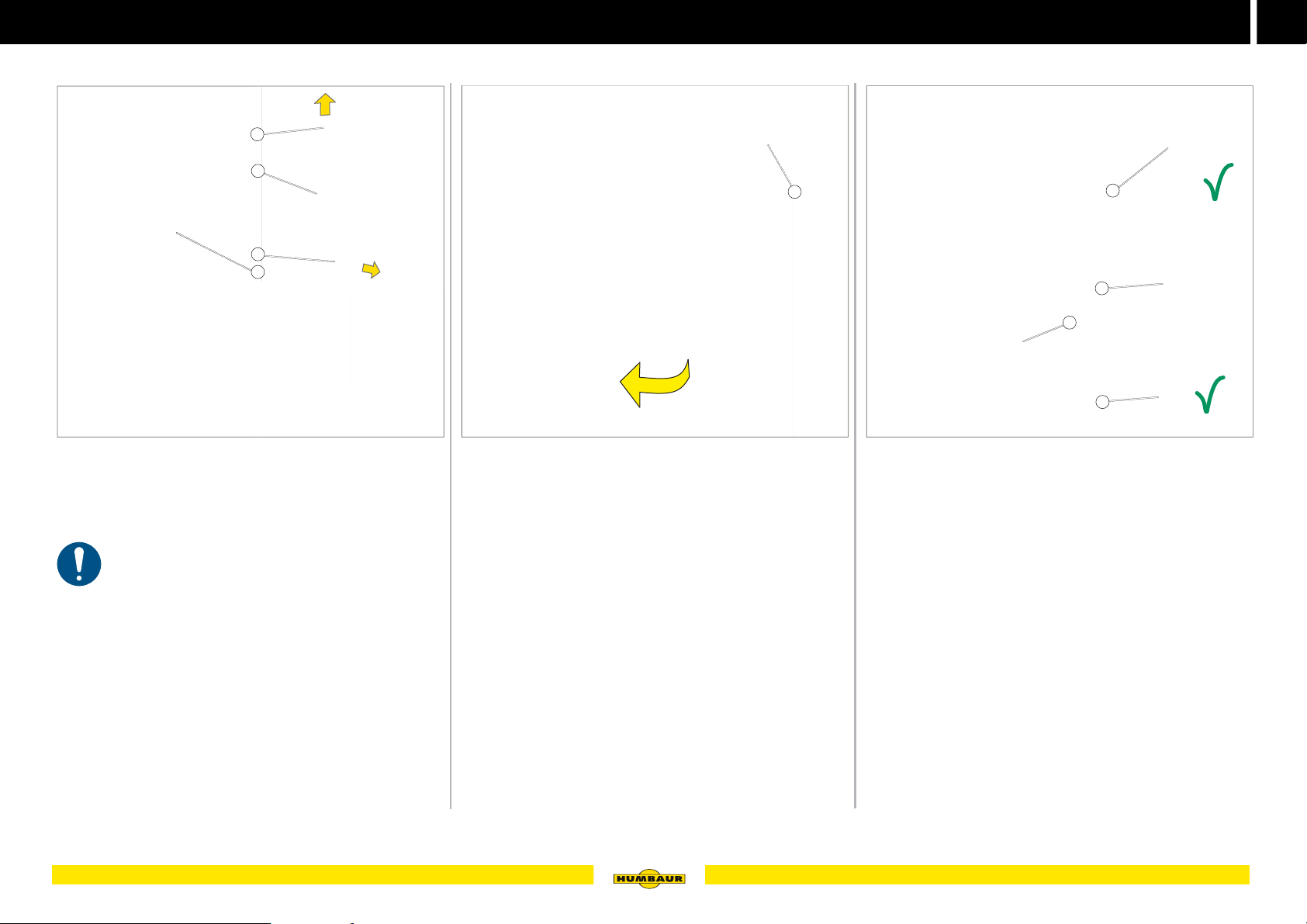
Fig. 39 Unlock the revolving door at the bottom
1 Plug pin
2 Revolving door lock
3 R-clip
The angle lever lock at the hinge side must be
closed.
Remove the R-clip (Fig. 39 /3) from the
plug pin (Fig. 39 /1).
Remove the plug pin from the
revolving door lock (Fig. 39 /2).
The revolving door is now unlocked at the bottom.
Keep the plug pin in a safe place.
A - 039
A - 040
Fig. 40 Swivel open the revolving door
1 Angle lever lock
Release the angle lever locks (Fig. 40 /1) at the front side
- see page 44.
Grab the handle at the revolving door and swivel the
revolving door open.
Hold the revolving door with your hand and secure it
against unintentional slamming.
A - 041
Fig. 41 Close the revolving door
1 Handle
2 Angle lever lock
3 Plug pin
4 R-clip
Grab the handle (Fig. 41 /1) and swivel the rotary door to
close it.
Lock the angle lever lock (Fig. 41 /2) - see page 44.
Secure the front exit with the safety bolt (Fig. 41 /3) and
the R-clip (Fig. 41 /4).
55Operating the body
Page 56

5
MACHT’S MÖGLICH
Deflector / roll-up tarpaulin
Operating the deflector / roll-up tarpaulin
Fig. 42 Example of Maximus deflector
The deflector protects the trailer against air-stream
turbulence and is permeable to air.
A - 042
Fig. 43 Example Xanthos roll-up tarpaulin
The roll-up tarpaulin is air tight.
A - 043
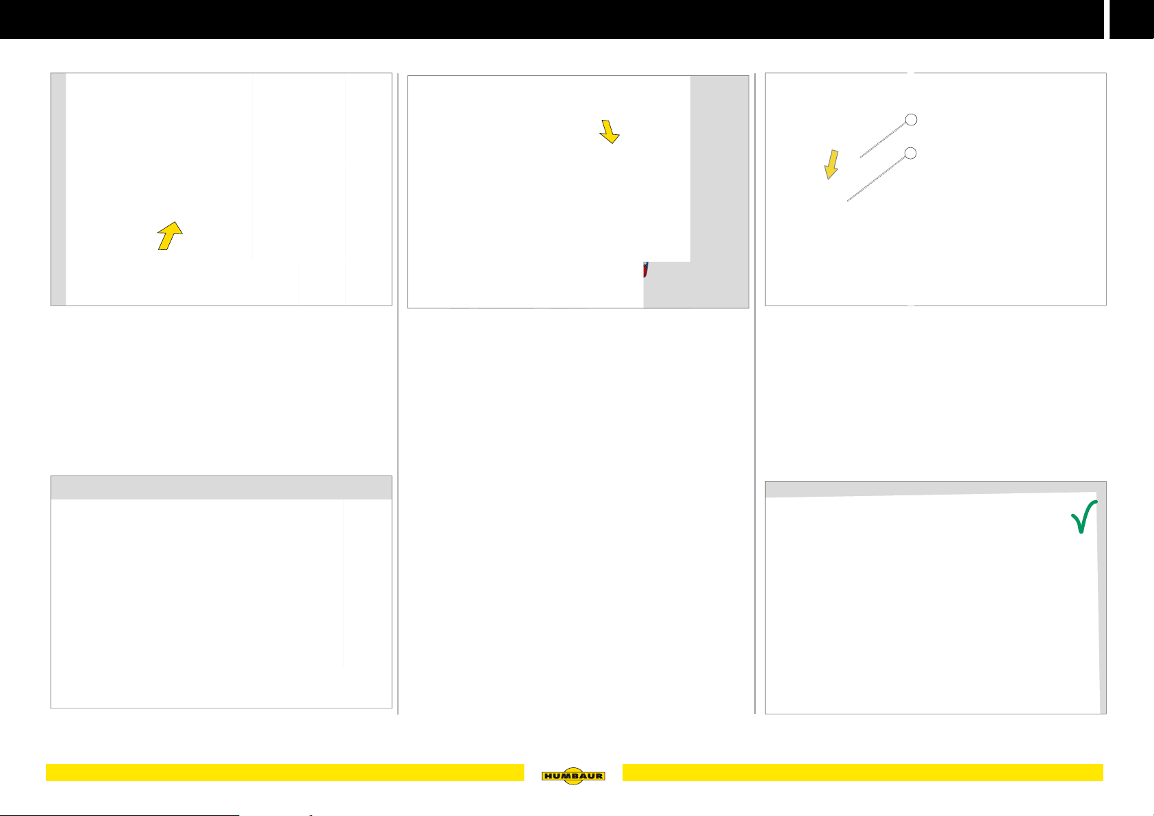
Opening the deflector / roll-up tarpaulin
1
2
A - 044
Fig. 44 Opening the elastic cord fasteners
1 Elastic cord fastener
2 Round button
The elastic cord fasteners must be opened from the
outside.
DANGER
Driving with open deflector / roll-up tarpaulin
The trailer may start to lurch due to the penetrating wind accident risk!
Make sure that the deflector / roll-up tarpaulin is closed
and secured before driving off.
56 Operating the body
CAUTION
Stepping onto the step
You may slip when stepping onto the step - risk of
falling!
Take particular care when stepping onto the step.
- Try to step onto it with your entire foot.
Hold on to the tailgate.
The deflector / roll-up tarpaulin must be evenly
stretched within the polyester roof.
Pull the elastic cord fastener downwards (Fig. 44 /1).
Detach the elastic cord fastener from the
round button (Fig. 44 /2).
Keep holding on to the middle elastic cord fastener.
Page 57
MACHT’S MÖGLICH
Closing the deflector / roll-up tarpaulin
Deflector / roll-up tarpaulin
1
2
5
A - 045
Fig. 45 Roll up the deflector / roll-up tarpaulin
Climb onto the step.
- Grip the tailgate.
Pull the deflector / roll-up tarpaulin up to the polyester
roof.
- Ensure that the deflector / roll-up tarpaulin rolls up
properly.
A - 047
Fig. 47 Pull down the deflector / roll-up tarpaulin
Climb onto the step.
- Grip the tailgate.
Slowly pull the middle elastic cord fastener downwards.
- Ensure that the deflector / roll-up tarpaulin rolls down
properly.
A - 048
Fig. 48 Closing the deflector / roll-up tarpaulin
1 Elastic cord fastener
2 Round button
Pull the elastic cord fasteners (Fig. 48 /1) over the
round buttons (Fig. 48 /2).
Fig. 46 Deflector / roll-up tarpaulin rolled up
A - 046
A - 049
Fig. 49 Deflector / roll-up tarpaulin closed
57Operating the body
Page 58
5
MACHT’S MÖGLICH
WARNUNG WARNING
Geöffnete Windflap /
GFK-Klappe!
Unfallgefahr während der Fahrt Schleudergefahr.
X Schließen und sichern Sie
die Windflap / GFK - Klappe
vor Fahrtantritt.
620.00276_A
Opened windflap /
GRP flap!
Increased risk of accidents during
the trip - risk of skidding.
X Close and secure the windflap
/ GRP flap before driving.
GFR tailgate (optional)
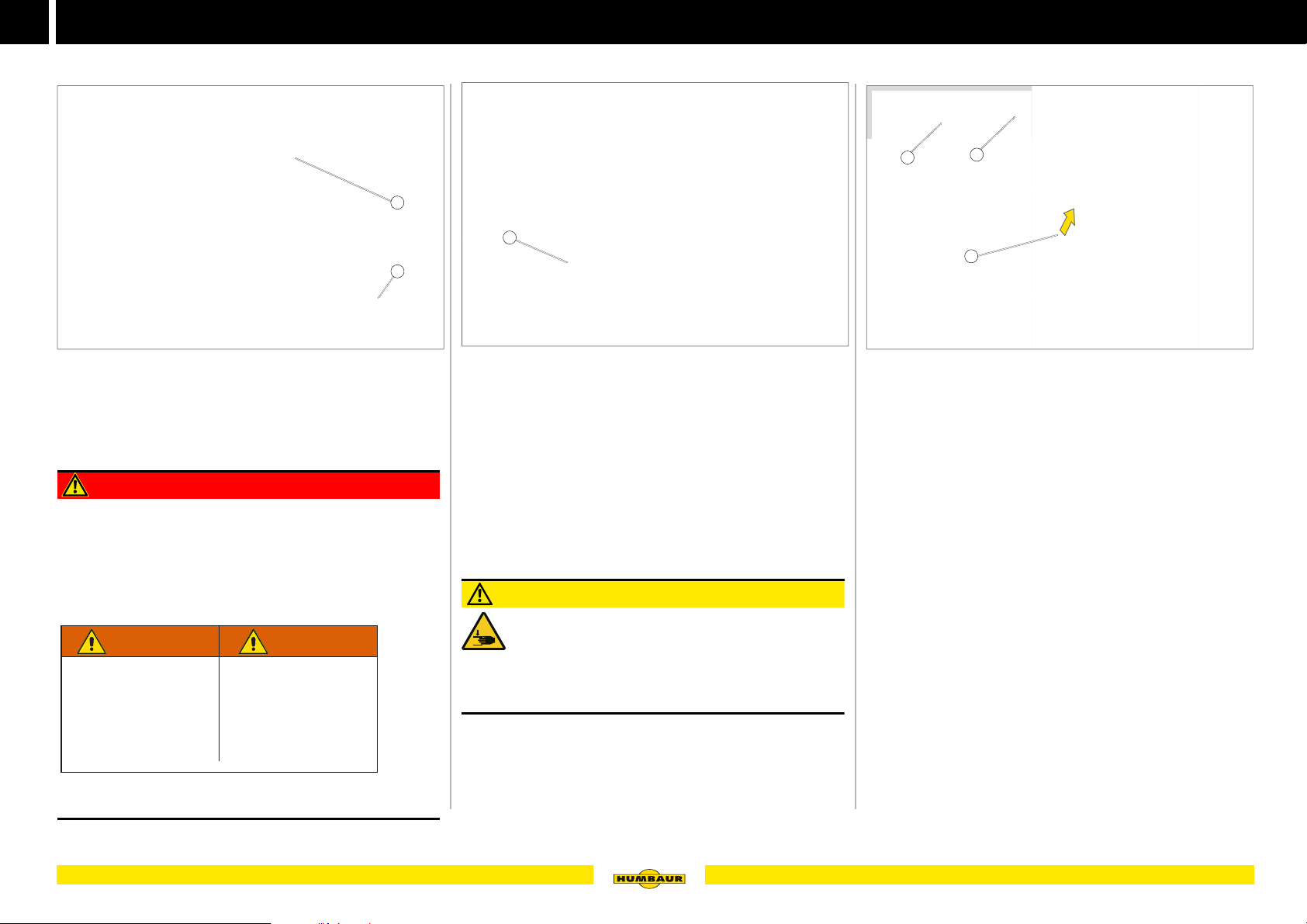
GFR tailgate
1
2
A - 050
Fig. 50 GFR tailgate closed
1 Ventilation opening
2 Elastic cord fastener
DANGER
Unsecured GFR tailgate
The GFR tailgate may unintentionally open during the drive
- lurching - accident risk!
The GFR tailgate may be torn off when driving through
tunnels / underpasses - risk of impact!
Note the warning sticker on the body.
1
A - 051
Fig. 51 GFR tailgate open
1 Operating strap
The GFR tailgate is a full-polymer flap with integrated
ventilation opening for draft-free interior ventilation. The
GFR tailgate is equipped with gas struts that facilitate easy
opening and securing.
CAUTION
Operating the GFR tailgate
Fingers / hands may be crushed between the GFR
tailgate and the body during closing and locking.
Make sure that your fingers do not get between the GFR
tailgate and the body.
Opening the GFR tailgate
1
Fig. 52 Open the GFR tailgate (using the strap provided)
1 Elastic cord fastener
2 Round button
3 Operating strap
Pull the elastic cord fastener (Fig. 52 /1) off the round
button (Fig. 52 /2) on both sides.
Reach below the GFR tailgate and gently lift the GFR
flap.
Grab the operating strap (Fig. 52 /3).
Let the GFR tailgate open slowly towards the top.
2
3
A - 052
Make sure that the GFR tailgate is closed and secured
before driving off.
58 Operating the body
Page 59
MACHT’S MÖGLICH
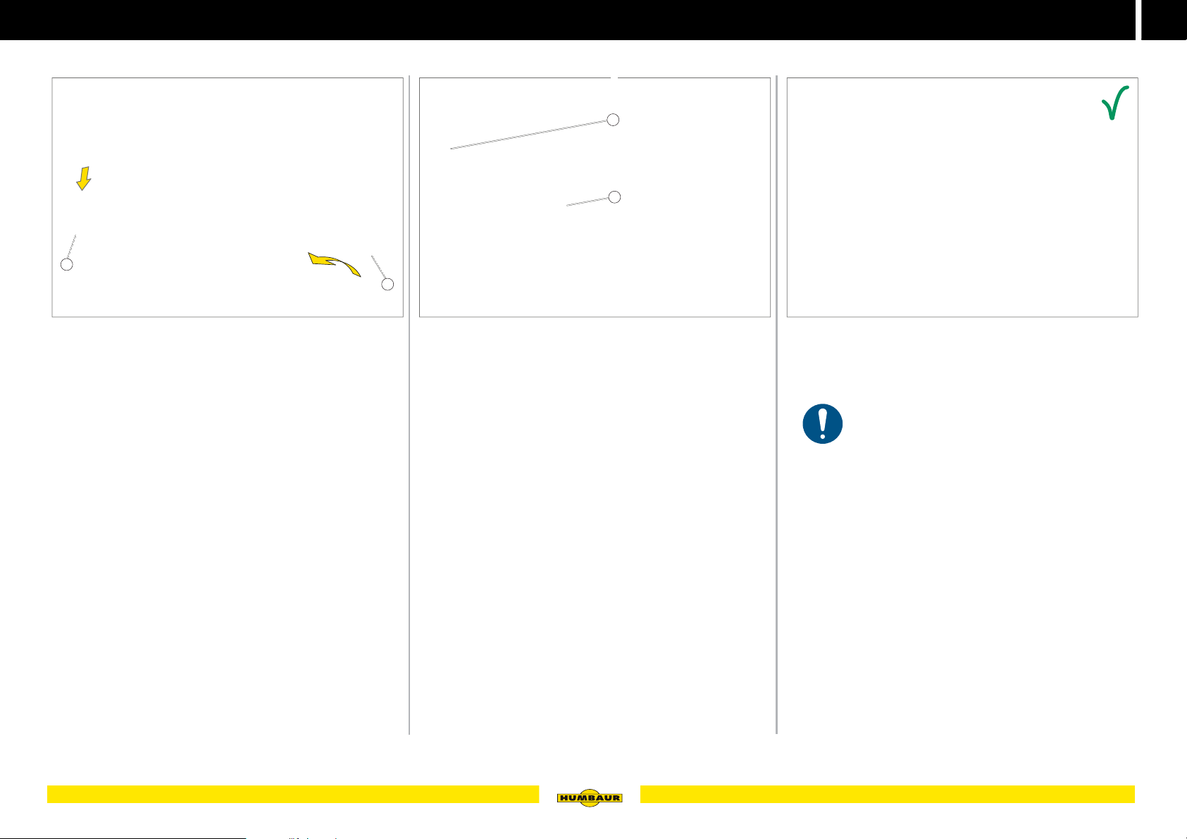
Closing the GFR tailgate
1
GFR tailgate (optional)
2
1
1
5
A - 053
Fig. 53 Pull down the GFR tailgate / store away the operating strap
1 Operating strap
Grab the operating strap (Fig. 53 /1).
Hold the GFR tailgate and fold the operating strap
towards the inside.
A - 054
Fig. 54 Close the elastic cord fasteners
1 Elastic cord
2 Round button
Press the GFR tailgate towards the body.
Pull the elastic cord fastener (Fig. 54 /1) over the round
button (Fig. 54 /2) on both sides.
A - 055
Fig. 55 GFR tailgate closed and secured
The operating strap must be inside the trailer.
59Operating the body
Page 60
5
MACHT’S MÖGLICH
Foal grid (optional)
Operating the foal grid
A - 056
Fig. 56 Foal grid
1 Securing pin
2 Foal grid (folded down)
3 Clamping bracket
The foal grid prevents small / young horses or foals from
jumping out of the trailer.
Folding up the foal grid
1
1
2
2
3
Fig. 57 Unlocking the foal grid
1 Securing pin
2 Holes
Open the deflector / roll-up tarpaulin - see page 56.
Pull the safety bolt (Fig. 57 /1) downwards.
- The safety bolt will fall out of the hole (Fig. 57 /2).
2
A - 057
1
2
A - 058
Fig. 58 Folding up the foal grid
1 Securing pin
2 Clamping bracket
Pull the foal grid out of the clamping bracket (Fig. 58 /2).
Fold the foal grid upwards and hold it.
Lock the foal grid with the safety bolt (Fig. 58 /1).
WARNING
Unsecured foal grid
The foal grid may unintentionally come open loose while
driving and fold down - accident risk!
The foal may jump out!
Make sure that the foal grid is closed and secured with
the safety bolt before driving off.
A - 059
Fig. 59 Foal grid folded up and secured
60 Operating the body
Page 61
MACHT’S MÖGLICH
Fold down the foal grid
A - 063
1
Foal grid (optional)
1
5
Fig. 60 Foal grid with deflector / roll-up tarpaulin
Pull the deflector / roll-up tarpaulin over the foal grid -
see page 57.
A - 060
Fig. 61 Unlock and fold down the foal grid
1 Securing pin
Open the deflector / roll-up tarpaulin - see page 56.
Hold the foal grid.
Unlocking of the safety bolts (Fig. 61 /1).
Fold the foal grid downwards.
A - 061
A - 062
Fig. 62 Secure the foal grid
1 Clamping bracket
Press the foal grid into the clamping bracket (Fig. 62 /1).
Lock the safety bolts.
Close the deflector / roll-up tarpaulin - see page 57.
A
Fig. 63 Foal grid folded down and secured
61Operating the body
Page 62
5
MACHT’S MÖGLICH
Rotary flaps (Notos ALU / PLUS) (optional)
Rotary flaps (Notos ALU / PLUS)
1
2
3
A - 064
Fig. 64 Rotary flaps closed
1 Ventilation slots
2 Rotary handle
3 Locking bolt
The Notos ALU and Notos PLUS models can be equipped
with double wing rotary flaps in addition to the deflector.
The rotary flaps are made of aluminium and are provided
with ventilation slots - for draft-free air circulation.
The rotary flaps can be opened and locked while driving.
The deflector ensures good air circulation.
1
2
Fig. 65 Rotary flaps opened / driving position
1 Deflector
2 Elastic cord fastener
3 Rotary flap (open)
A - 065
WARNING
Unsecured rotary flaps
The rotary flaps may swing to and fro while driving accident risk!
The rotary flaps may be torn off when driving through
tunnels / underpasses.
Check that the rotary flaps are closed and secured or
opened and secured at the sides before driving off.
Opening the rotary flaps
3
1
2
A - 066
Fig. 66 Unlocking and opening the rotary flap
1 Rotary flap
2 Rotary handle
Unlock the rotary handle (Fig. 66 /2) - see page 44.
Open the left rotary (Fig. 66 /1) flap and secure it with the
locking bolt.
62 Operating the body
Page 63
MACHT’S MÖGLICH
Closing the rotary flaps
Rotary flaps (Notos ALU / PLUS) (optional)
5
2
1
Fig. 67 Secure the rotary flap
1 Locking bolt
2 Securing bracket
Pull up the locking bolt (Fig. 67 /1).
Turn the locking bolt / handle by 90°.
Let the locking bolt snap into the eyelet of the safety
bracket (Fig. 67 /2) by pressing it upwards as required.
The rotary flap is secured against unintentional
slamming.
A - 067
3
1
2
Fig. 68 Close the rotary flap
1 Securing bracket
2 Locking bolt
3 Rotary flap (left)
Remove the latch pin (Fig. 68 /2) from the safety
bracket (Fig. 68 /1).
Close the left rotary flap (Fig. 68 /3).
Unlock and close the right rotary flap.
A - 068
1
Fig. 69 Rotary flaps closed and secured
1 Rotary flap (left)
2 Rotary flap (right)
2
A - 069
Press the left rotary flap (Fig. 69 /1) towards the body
and close the right rotary flap (Fig. 69 /2).
Lock the rotary handle - see page 44.
63Operating the body
Page 64
5
MACHT’S MÖGLICH
Tailgate
Tailgate
1
2
3
4
5
6
7
Fig. 70 Tailgate closed
1 Deflector
2 Angle lever locks
3 Tailgate (revolving door function)
4 Handle
5 Gas strut
6 Lock (revolving door)
7 Hinge (revolving door)
A - 070
A - 071 A - 072
Fig. 71 Tailgate folded down
The tailgate may only be folded down while
standing on even ground.
The tailgate provides an angled ramp that is an optimal
entrance into the trailer.
A tailgate with a revolving door function can optionally be
installed.
Fig. 72 Tailgate folded open
64 Operating the body
Page 65
Tailgate
MACHT’S MÖGLICH
5
Folding down the tailgate
Fig. 73 Folding down the tailgate
1 Tailgate
Release the angle lever locks - see page 44.
Use , .
Grip the upper edge of the tailgate (Fig. 73 /1).
1
A - 073
1
Fig. 74 Tailgate folded down
1 Angle lever lock
Carefully lower the tailgate.
- If necessary, push it downwards a little.
- Make sure that your hands / feet cannot be crushed.
Turn the angle lever locks (Fig. 74 /1) towards the
tailgate - risk of tripping!
A - 074
Folding up / closing the tailgate
A - 075
Fig. 75 Lifting the rear flap
Grip the lower edge of the tailgate in the middle.
Lift the tailgate upwards - the gas struts will assist in the
process.
1
A - 076
Fig. 76 Closing the tailgate
1 Handle
Grab the handle (Fig. 76 /1).
Press the rear flap completely towards the body.
65Operating the body
Page 66
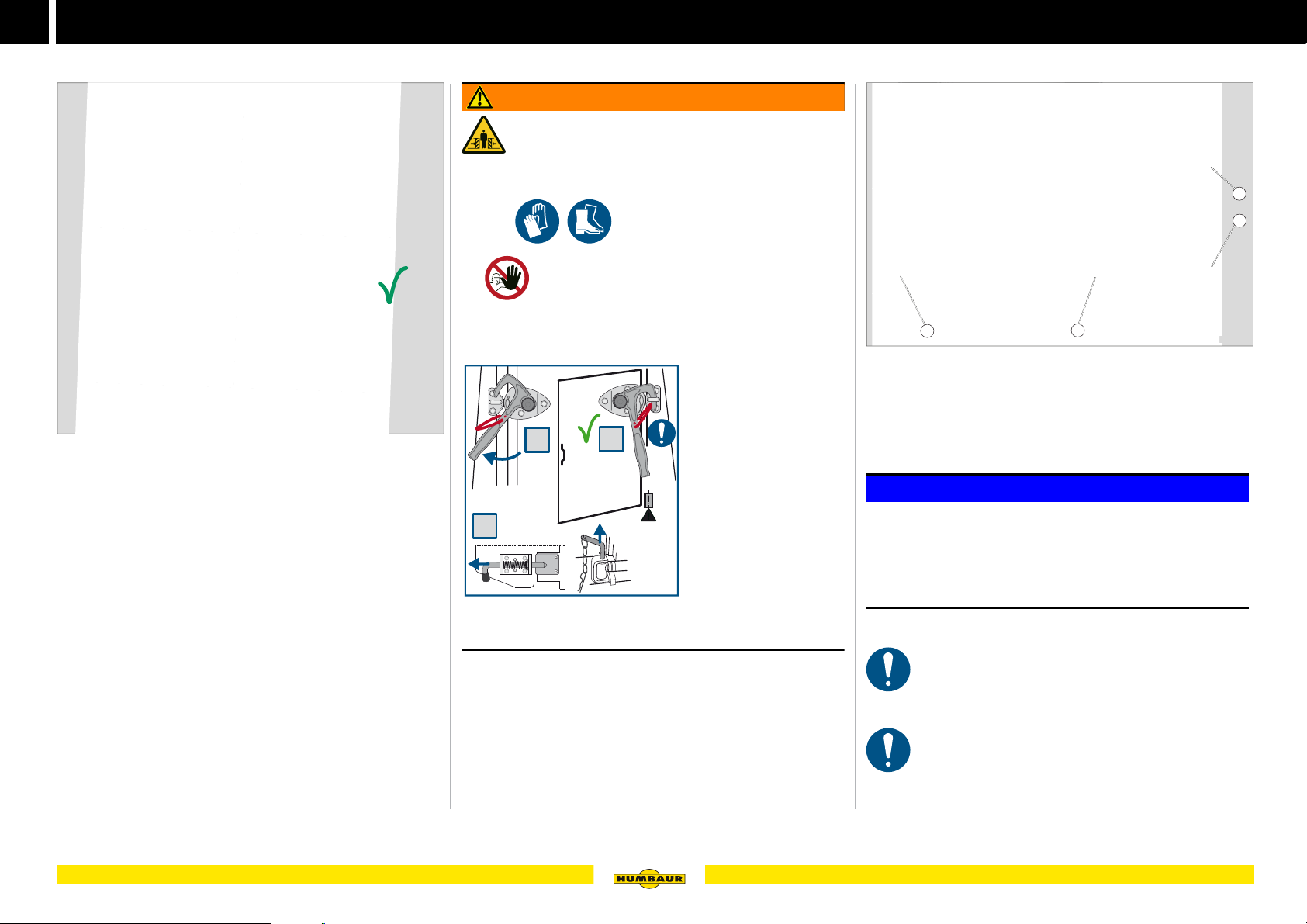
5
MACHT’S MÖGLICH
620.00403_A
3
2
1
A
Tailgate
Fig. 77 Tailgate closed and secured
A - 077
Swivel open the revolving door
WARNING
Swivelling open the revolving door
After unlocking, the revolving door can fold
open or fold down in an uncontrolled manner
- impact / crushing risk!
Use , .
Keep persons out of the swivelling range of the
tailgate.
Stick to the sequence for unlocking the revolving door -
see sticker.
1
Fig. 78 Revolving door
1 Plug pin lock
2 Hinge
3 Handle
4 Angle lever lock
4
3
2
A - 078
Lock the angle lever locks - see page 44.
Close the deflector / roll-up tarpaulin - see page 57.
66 Operating the body
NOTICE
Overextending the revolving door
The hinges of the revolving door and the lamps at the rear
support can get damaged.
Only swivel the revolving door up to the limit stop or as
far as this can be done without damaging components.
Never unlock both angle lever locks.
Hold the revolving door with one hand.
The angle leaver lock at the hinge side remains
closed.
The revolving door does not have a door holder.
The revolving door must be secured against falling
shut!
Page 67
Tailgate
MACHT’S MÖGLICH
1
2
5
3
2
1
Fig. 79 Releasing the plug pin lock
1 R-clip
2 Lock
3 Plug pin
Remove the R-clip (Fig. 79 /1) from the
plug pin (Fig. 79 /3).
Remove the plug pin from the revolving door
lock (Fig. 79 /2).
Keep the plug pin in a safe place.
A - 079
3
A - 080
Fig. 80 Unlock the locking bolt lock (Spirit, Balios)
1 Plunger pins
2 Securing pins
3 Locking bolt
Pull the locking bolt (Fig. 80 /3).
Turn the locking bold by 90° downwards and lock the
safety pins (Fig. 80 /2) behind the latching
pins (Fig. 80 /1).
The revolving door is now unlocked at the bottom.
1
A - 081
Fig. 81 Swivel out revolving door / open
1 Handle
Unlock the left angle leaver lock - see page 44.
Grip the handle (Fig. 81 /1) of the revolving door.
Swivel the revolving door to open it - up to the limit stop.
Hold the revolving door with your hand or secure it
against unintentional slamming.
67Operating the body
Page 68
5
MACHT’S MÖGLICH
Tailgate
Closing / securing the revolving door
Fig. 82 Close the revolving door
1 Handle
1
A - 082
3
2
1
A - 083
Fig. 83 Secure the locking plug pin lock
1 R-clip
2 Revolving door lock
3 Plug pin
Remove the plug pin (Fig. 83 /3) from the revolving door
lock (Fig. 83 /2).
Secure the plug pin with the R-clip (Fig. 83 /1).
A - 085
Fig. 85 Revolving door closed and secured
Grab the handle (Fig. 82 /1) and carefully swivel the
revolving door to close it - lifting it slightly as required.
Lock the angle lever lock - see page 44.
68 Operating the body
1
A - 084
Fig. 84 Secure the locking bolt lock
1 Locking bolt
Turn the locking bolt (Fig. 84 /1) upwards by 90°.
Allow the locking bolt to latch, pressing it in towards the
right side as required.
The locking bolt locks the revolving door at the bottom.
Page 69
Vent window
MACHT’S MÖGLICH
5
Operating the vent window
Fig. 86 Vent window open on both sides
The vent windows are used for fresh air supply during
parking and while driving.
The vent windows can be opened in 5 positions.
CAUTION
Operating the vent window
Risk of crushing your hands / fingers when opening
or closing the vent windows.
Carefully operate the vent windows.
- Pull it towards you with one hand.
- Only operate one handle at a time - not both.
A - 086
A - 087
Fig. 87 Risk of collision
NOTICE
Opening the access door with opened vent window!
The vent window knocks against the body of the trailer and
may get damaged.
Close the vent window before opening the access door.
Vent windows Positions
A - 088
Fig. 88 closed / open in parallel
A - 089
Fig. 89 folded upwards / folded downwards
NOTICE
Vent window open
Water / rain may penetrate to the inside and cause humidity
damage if the window is open.
Close the vent windows in bad weather.
A - 090
Fig. 90 open towards the back / towards the front
69Operating the body
Page 70
5
MACHT’S MÖGLICH
Vent window
Open vent window
Fig. 91 from outside / from inside
1 Handle
2 Safety rods
Closing the vent window
1
2
A - 091
Fig. 93 Push open the vent window
Push the handle outwards.
- Depending on the vent position you want, repeat the
process with the 2nd handle.
1
The vent window is open.
A - 093
A - 094
Fig. 94 Pull the vent window shut
Grab the upper or lower handle and pull the vent window
towards the inside.
The vent window is closed.
2
Fig. 92 from outside / from inside
Grab one of the handles (Fig. 91 /1), depending on the
venting position.
- Take care to avoid crushing by the safety
struts (Fig. 91 /2).
70 Operating the body
A - 092
Page 71
Skylight / roof vent (optional)
MACHT’S MÖGLICH
5
Operating the skylight / roof vent
1
A - 095
Fig. 95 External view
1 Skylight / roof vent
A skylight / roof vent can optionally be installed and ensures
fresh air supply during parking and while driving.
The skylight can be opened in 5 positions.
CAUTION
Operating the skylight / roof vent
Risk of crushing your hands / fingers when opening
or closing the skylight / roof vent.
Operate the skylight / roof vent carefully.
- Pull it towards you with one hand.
- Only operate one handle at a time - not both.
1
A - 096
Fig. 96 Internal view
NOTICE
Skylight / roof vent open
Water / rain may penetrate to the inside and cause humidity
damage if the window is open.
Close the skylights / roof vents in bad weather.
A stool is required as a climbing aid in order to
operate the skylight / roof vent.
Opening / closing the skylight
2
1
3
A - 097
Fig. 97 Skylight opened (in driving direction)
1 Handle - left
2 Safety rod
3 Skylight (open)
Operation is the same as for the vent window -
see page 70.
71Operating the body
Page 72
5
MACHT’S MÖGLICH
Ventilation window (Notos ALU) (optional)
Operating the ventilation window (Notos ALU)
A - 098
Fig. 98 Ventilation window closed / open
The ventilation window is used for fresh-air supply while
parking.
The integrated vent window in the ventilation window
ensures fresh air while driving.
Operation from the outside
Opening the ventilation window
1
2
3
Fig. 99 Push open the ventilation window
1 Ventilation window
2 Rotary handle
3 Holder
Unlock the rotary handle (Fig. 99 /1) - see page 44.
Carefully swivel and open the ventilation
window (Fig. 99 /2).
Lock the ventilation window in the
holder (Fig. 99 /3) - see page 45.
Closing the ventilation window
Operation from the inside
Opening the ventilation window
1
A - 099
A - 101
Fig. 101 Opening the ventilation window from the inside
1 Rotary knob
Unlock the rotary knob - see page 44.
Push the ventilation window open.
Lock the ventilation window from the outside in the holder
- see page 45.
The vent window must be closed before opening
the ventilation window - risk of collision with the
body.
The ventilation window must be closed and
secured before driving off!
The ventilation window must be closed from the
outside!
72 Operating the body
A - 100
Fig. 100 Push the ventilation window closed
Unlock the holder - see page 45.
Lock the rotary handle - see page 44.
Page 73
Sliding window (Notos PLUS)
MACHT’S MÖGLICH
A - 106
5
Sliding window (Notos PLUS)
1
2
A - 102
Fig. 102 Sliding window
1 Sliding window closed
2 Sliding window open
The windows can optionally be installed as sliding windows
for good ventilation while parking.
Operation is only possible from the inside
Open the sliding window
1
Fig. 103 Open the sliding window
1 Handle
Push the handle (Fig. 103 /1) together.
The sliding window is unlocked.
Hold the window handle and slide the window open.
A - 103
Closing the sliding window
A - 105
Fig. 105 Closing the sliding window
Hold the window handle and slide the window closed.
Fig. 104 open
A - 104
Fig. 106 locked
The handle must engage.
73Operating the body
Page 74
5
MACHT’S MÖGLICH
Lose Brust- / Heckstangen!
Herunterfallende Stangen während
der Fahrt - Gewichtsverlagerung
durch Pferd / Schleudergefahr.
Hängen und sichern
Sie die Brust- / Heckstange
vor Fahrtantritt ein.
Loose breast / breech bars!
Falling bars while driving - weight
transfer by horse / danger of
skidding.
Engage and secure the
breast / breech bars before
driving.
620.00275
WARNUNG
WARNING
A - 110
Breast and breech bar
Breast and breech bars
Fig. 107 Breast and breech bar (single)
Fig. 108 Breast and breech bar with central partition wall
The breast / breech bars must be hooked in and
secured during the drive!
A - 107
A - 108
Securing / unlocking the breast and breech bar
1
2
3
4
Fig. 109 Unlocking (single)
1 Hook
2 Securing pin
3 Eyelet
4 Hook-in rail (on the side wall)
4
2
3
1
Fig. 110 Securing
Releasing
Pull the hook (Fig. 109 /1) out of the eyelet (Fig. 109 /3)
on both sides
Remove the safety bolt (Fig. 109 /2) from the
hook-in rail (Fig. 109 /4).
A - 109
Unhook / hook-in the breast and breech bar
A - 111
Fig. 111 to be moved (single)
Lift the breast / breech bar out of the eyelets in the hook-
in rail.
1
3
Fig. 112 Unhook
1 Hook
2 Eyelet
3 Breast / breech bar
Swivel the breast or breech bar (Fig. 112 /3) downwards.
Lift the hooks (Fig. 112 /1) of the breast / breech bar out
of the eyelet (Fig. 112 /2).
2
A - 112
74 Operating the body
Securing
Hang the safety bolt (Fig. 110 /2) into the
hook-in rail (Fig. 110 /4).
Push the hook (Fig. 110 /1) through the
eyelet (Fig. 110 /3).
Page 75
Breast and breech bar
MACHT’S MÖGLICH
A - 115
5
Panic locking
1
3
Fig. 113 Panic locking from the outside
1 Tie-ring (front)
2 Tie-ring (rear)
3 Tie-ring (detailed view)
The panic locking allows for fast unlocking of the breast and
breech bar from the outside. They should only be activated
in emergencies, e.g. if the horse panics.
The breast / breech bars automatically fall down.
2
A - 113
Releasing the panic locking
1
2
Fig. 114 releasing from the outside
1 Tie-ring
2 Hoof scraper
Insert the hoof scraper (Fig. 114 /2) into the
tie-ring (Fig. 114 /1).
Turn the hoof scraper counter-clockwise.
A - 114
Locking the panic locking
1
2
3
4
A - 116
Fig. 116 Attaching the hook-in rail
1 Holder
2 Fastening rail
3 Holes
4 Tie-ring
Slide the fastening rail (Fig. 116 /2) into the
holder (Fig. 116 /1).
Push the tie-ring (Fig. 116 /4) through the
hole (Fig. 116 /3).
Turn the tie-ring until it is tight.
The hook-in rail is tightened.
1
Fig. 115 releasing from the inside
1 Threaded bolt (tie-ring)
The hook-in rail is detached from the fastening rail - the
horse is no longer secured.
A - 117
Fig. 117 The hook-in rail in position
75Operating the body
Page 76
5
MACHT’S MÖGLICH
Central partition wall
Central partition wall
1
A - 118
Fig. 118 Interior view
1 Central partition wall
The central partition wall prevents the horse from tilting
sideways and being flung around.
The central partition wall spatially separates two horses and
ensures form-fitting safety.
A - 119
Fig. 119 Central partition wall not secured
WARNING
Driving with an unsecured central partition wall!
The goods / horse in the trailer may be flung around. The
trailer may start to lurch – accident risk!
Make sure that the central partition wall is closed and
secured before driving off.
Releasing / removing the central partition wall
1
A - 120
Fig. 120 Releasing the lock
1 Locking lever
Remove the breast and breech bars - see page 74.
Turn the locking lever sideways (Fig. 120 /1) by 90°
sideways.
- the post of the central partition wall is unlocked.
1
76 Operating the body
Removal / installation of the central partition wall
requires 2 persons.
2
A - 121
Fig. 121 Swivel the central partition wall
1 Post (rear)
2 Locking mechanism in the floor (rear)
Lift the centre post (Fig. 121 /1) out of its locking
mechanism on the floor (Fig. 121 /2).
Swivel the central partition wall to the left.
Page 77
MACHT’S MÖGLICH
Inserting the central partition wall
Central partition wall
2
1
5
1
A - 122
Fig. 122 Removing the central partition wall
1 Front lock
Lift the centre post (front) out of its locking mechanism on
the floor (front).
Lift the central partition wall up and remove it.
Deposit the central partition wall secured against falling
over.
1
A - 124
Fig. 124 Inserting the central partition wall
1 Front lock
2 Rear lock
Position the central partition wall with the post above the
locking mechanism front / rear.
Insert the central partition wall.
Swivel the central partition wall towards the middle.
A - 125
Fig. 125 Central partition wall secured
1 Locking lever, secured
Turn the locking lever (Fig. 125 /1) towards the central
partition wall.
Secure the central partition wall with the breast and
breech bars - see page 74.
Fig. 123 Deinstalled central partition wall
A - 123
77Operating the body
Page 78
5
MACHT’S MÖGLICH
Head partition (optional)
Head partition
Fig. 126 Head partition in place / resting position
1 Head partition
2 Allen key
3 Central partition wall,
Moving the head partition
1
2
1
2
3
A - 126
Fig. 128 Detach the head partition
1 Allen key
2 Allen screw
3 Holder
Remove the Allen key (Fig. 128 /1) from the
holder (Fig. 128 /3) - pull it up and out.
3
A - 128
Secure the head partition
2
3
Fig. 130 Secure the head partition
1 Head partition (placed in front)
2 Allen key
3 Allen key (secured in holder)
1
A - 130
Unlock the head partition with an Allen key - remove the
hexagon socket screw (Fig. 128 /2).
Secure the head partition (Fig. 130 /1) with an Allen key
- tighten the hexagon socket screw.
Place the Allen key into the holder - push it in from the
top.
The head partition has been positioned and secured.
Fig. 127 Head partition in driving position
An optional head partition can be attached on top of the
centre partition wall in the Balios, Xanthos, Zephir,
Maximus, Notos ALU and Notos PLUS models.
78 Operating the body
A - 127
2
1
Fig. 129 Shift / lock the head partition wall
1 U-bracket
2 Central partition wall,
Gently lift the head partition, so that the
U-bracket (Fig. 129 /1) detaches from the central
partition wall (Fig. 129 /2).
Slide the head partition forwards into the desired
position.
A - 129
The head partition can be removed when it is not
needed.
Please read the separate assembly instructions
for installing / removing the head partition.
Page 79
Central partition wall (Notos) (optional)
MACHT’S MÖGLICH
5
Operating the central partition wall
1
2
3
4
5
Fig. 131 Central partition walls (Notos)
1 Roof mounting
2 Centre post
3 Central partition wall (two-part)
4 Height adjustment
5 Locking mechanism on the floor
A - 131
Fig. 132 Turned position of the central partition wall (Notos)
Removing the central partition wall
1
2
A - 133
Fig. 133 Detaching the centre post
1 Centre post
2 Screw connection
A - 132
Remove the breast and breech bar - see page 74.
Detach the screw connection (Fig. 133 /2) of the centre
post (Fig. 133 /1) at the roof.
The central partition wall of the Notos ALU can be turned for
optimal handling.
NOTICE
Unsecured central partition wall
The central partition wall may move to and fro while driving.
The central partition wall may get deformed and the interior
walls may get damaged.
Make sure that the central partition wall is secured
before driving off.
Removal / installation of the central partition wall
requires 2 persons.
79Operating the body
Page 80
5
MACHT’S MÖGLICH
Central partition wall (Notos) (optional)
Central partition wall height adjustment
1
2
A - 134
Fig. 134 Adjusting the height of the central partition wall.
1 Screw connection
2 Lowest level (height adjustment)
Release the screw connection (Fig. 134 /1) of the height
adjustment.
Set the height adjustment to the lowest
level (Fig. 134 /2).
Secure it, using the screw.
Lift the centre post out of its locking mechanism on the
floor.
Remove the central partition wall from the trailer.
Installing the central partition wall
1
2
Fig. 135 Insert the centre post
1 Centre post
2 Locking mechanism on the floor
Place the centre post (Fig. 135 /1) onto the locking
mechanism (Fig. 135 /2) on the floor.
Set the height adjustment to the highest level -
see Fig. 134 .
A - 135
1
2
A - 136
Fig. 136 Secure the centre post
1 Roof bracket
2 Centre post
Fasten the centre post (Fig. 136 /2) to the
roof bracket (Fig. 136 /1).
Fasten the breast and breech bars - see page 74.
80 Operating the body
A - 137
Fig. 137 Central partition wall (pivoting) secured
Page 81

MACHT’S MÖGLICH
6
Electrical system
81
Page 82
6
MACHT’S MÖGLICH
E - 003
Exterior lighting
Take note of the safety instructions and instructions
for the electric systems in the operating instruction
manual,
“Trailers up to 3.5 to” General Points – Part 1.
The electric lighting system operates with 12 V as standard.
WARNING
Risk of short circuit / electrocution!
You could be exposed to dangerous voltage or
cause a fire through a short circuit in the electric
systems when carrying out work on the electric
systems.
Observe the following points before working on the
electrical system:
Loosen all plug-type connections to the towing vehicle.
Loosen all plug-type connections to external
power supplies.
Switch off all power consumers.
Ensure that nobody else switches on the power supply.
Have all work on electrical installations carried out by
qualified specialist staff.
WARNING
Failure of electrical functions
The road handling and the braking distance deteriorate accident risk!
Check that all electrical connections have been assem-
bled before driving off.
Check the condition of the plugs and cables before
driving off.
Do not drive with cracked or defective electric systems
connections.
Tail lights
1
2
3
4
5
Fig. 1 Individual lights (standard)
4
3
1
2
5
Fig. 2 LED lights for Maximus upgrade (optional)
2
3
4
5
1
Fig. 3 Humbaur multifunctional lighting for
Single / Xanthos / Balios / Notos / Zephir
1 Indicator
2 brake light
3 Rear fog light
4 Reversing light
5 Triangular reflector
E - 001
E - 002
Side / position lamps
1
3
Fig. 4 Side / rear view (Maximus Upgrade)
3
4
Fig. 5 In the fender area - front
1 Top position lamp
2 Registration number light
3 Side reflector / yellow reflector
4 Front reflector / white reflector
5 Front position lamp
3
5
2
E - 004
3
5
E - 005
82 Electrical system
Page 83
Interior lighting
MACHT’S MÖGLICH
6
Interior lighting
1
2
E - 006
Fig. 6 Interior light
1 Light
2 Toggle switch
The interior light is located in the front or middle area of the
trailer.
The interior light only works when at least the side light of
the towing vehicle has been switched on.
The interior light can be used for loading / unloading in the
dark and as a light for the horse while driving.
Switch the light (Fig. 6 /1) on or off using a
toggle switch (Fig. 6 /2).
If necessary, use an access aid to operate the light, e.g.:
stool.
Replace any faulty lamp - see page 92.
Saddle compartment lighting
1
2
3
4
E - 007
Fig. 7 LED light with movement detector
1 LED light / head
2 Switch
3 Holder
4 Movement detector
A battery-driven LED lamp with movement detector can
optionally be integrated into the saddle compartment. The
head of the LED lamp is swivel-mounted.
Turn the head of the LED lamp (Fig. 7 /1) according to
the lighting requirements.
Slide the switch (Fig. 7 /2) upwards
- the LED light remains on.
Slide the switch downwards
- the movement detector is now active.
Slide the switch to the middle position
- the LED light is now off.
Replaced used batteries - see page 92.
Panorama sunroof (Maximus Upgrade)
E - 008
Fig. 8 Panorama sunroof external view
The Maximus can be optionally equipped with a transparent
panorama sunroof.
The panorama sunroof allows for a maximum amount of
sunlight in the trailer.
2
1
E - 009
Fig. 9 Panorama sunroof internal view
1 Panorama sunroof
2 LED strip (right / left)
LED strips (Fig. 9 /2) can be optionally installed.
83Electrical system
Page 84
6
MACHT’S MÖGLICH
Distributor box / power connection (230 V AC)
Optional mains supply (230 V AC)
1
2
3
4
E - 010
Fig. 10 External power connection
1 Mains supply
2 Technical data
3 Plug contacts
4 Lid
A power connection, for example for the Notos PLUS, can
be equipped with a distributor / fuse box and sockets on the
inside.
The mains voltage is 230 V / 50 Hz.
1
2
3
4
E - 012
Fig. 12 Power distributor box / circuit breaker
1 Power distributor box
2 Lid
3 Residual-current circuit breaker
4 Overcurrent protection device
Standard: 16 A
Switzerland: 10 A
The power distributor box (Fig. 12 /1) is attached to the
inner wall of the trailer.
The safety and function of the power supply are tested in
the factory and documented. The test record is enclosed
with the power distributor box.
Protection against leakage current takes the form of a
safety switch (30 mA) (Fig. 12 /3) and an overcurrent
protection device (Fig. 12 /4).
1
2
E - 013
Fig. 13 Sockets
1 Earthed twin socket (Europe)
2 Twin socket (Switzerland)
The sockets are standard earthed sockets (Fig. 13 /1) (for
European plugs).
Country-specific sockets can be optionally installed, e.g. for
Switzerland (Fig. 13 /2).
The standard sockets are located directly below the power
distributor box.
Fig. 11 Adapter cable 2.5 m long with power plug
The power supply can be provided by means of an adapter
cable with power plug (optional).
84 Electrical system
E - 011
Page 85

MACHT’S MÖGLICH
7
Testing,
care and maintenance
85
Page 86
7
MACHT’S MÖGLICH
Safety inspection
Basic information about repairs and maintenance
Note the maintenance regulations in the operating
instruction manual
“Trailers up to 3.5 to” General – Part 1.
Certain maintenance work may only be carried out
by trained and qualified personnel.
The prescribed maintenance intervals must be
complied with.
Trailers must be inspected by a competent / qualified
specialist for their condition for safe operation as and when
required, but at least once a year.
This also applies to all components which are used for the
load securing according to VDI 2700 or / and EN 12642.
All important mechanical components must be inspected
and maintained at regular intervals for safety reasons.
These include:
–Axles
– Brakes
–Bolts
– Pipe connections
– Attachments
– Electric systems
– Comply with the accident prevention regulations for all
maintenance work.
– Comply with the environmental protection guidelines.
– Switch off the engine of the towing vehicle prior to
starting maintenance work.
– Damaged and non-functioning trailer parts must be
exchanged for original spare parts of Humbaur GmbH.
Proof of the HU/SP
W - 001 W - 002
Fig. 1 Proof of inspection (in operating instruction manual,
“Trailers up to 3.5 to” Part 1)
HU = General inspection
SP = Safety inspection
Enter the implemented HU/SP in the proof of inspection
(Section 29, sub-section 12 of the StVZO (German
Licensing Regulations)).
Keep the latest inspection report (HU) and the latest test
record (SP) at least until the next inspection / test
(Section 29, sub-section 10 of the StVZO).
Keep the inspection log book as proof until the vehicle is
finally taken out of service
(Section 29, sub-section 13 of the StVZO).
Maintenance of axles / wheels
Fig. 2 Example: Operating instruction manual for axles
Carry out the prescribed visual inspections and
maintenance work or have them carried out by qualified
specialist workshops.
Have the inspections documented in the service booklet.
86 Testing, care and maintenance
Page 87
MACHT’S MÖGLICH
Checking the tyres
Tyres/wheels
7
1
2
Fig. 3 Checking the wheels / tyres
1 Steel rim
2 Tyres (as selected by the manufacturer)
3
1
2
Fig. 4 Checking the wheels / tyres
1 Alloy rim
2 Tyres (as selected by the manufacturer)
3 Bicolor alloy rims
W - 003
W - 004 W - 004
Tyre type pmax.
Model
in bar
155 / 80 R13 3.0 Single / Zephir / Balios /
Spirit / Xanthos
155 R13 ; RF 3.5 Single / Zephir / Balios /
Spirit / Xanthos
175 / 70 R13 3.0 Single / Zephir / Balios /
Spirit / Xanthos
175 / 70 R14 3.0 Single / Zephir / Balios /
Spirit / Xanthos
185 / R14C - 8PR 4.5 Single / Zephir / Balios /
Spirit / Xanthos / Maximus
/ Notos / Notos PLUS /
carriage trailer
185 / 60 R15 3.5 Single / Zephir / Balios /
Spirit / Xanthos / Maximus
/ Notos
185 / 65 R14 3.0 Single / Zephir / Balios /
Spirit / Xanthos / Maximus
/ Notos / carriage trailer
185 / 65 R15 3.0 Single / Zephir / Balios /
Spirit / Xanthos / Notos
195 / 65 R14 3.0 Single / Zephir / Balios /
Spirit / Xanthos / Notos
195 R14C - 8PR 4.5 Notos PLUS
195 / 65 R15 3.0 Single / Zephir / Balios /
Spirit / Xanthos / Maximus
/ Notos / carriage trailer
195 / 65 R15 95N 3.0 Notos PLUS
195 / 70 R15C - 8PR 4.5 Notos PLUS
Tab. 1 Tyre pressure / tyre size
1
2
3
W - 005
Fig. 5 Check the spare wheel
1 Screw connection for spare wheel holder
2 Spherical collar nuts
3 Spare wheel
Use the correct tyre pressure as specified in this table
(Table 1 on page 87).
Check the tyre pressure / tread depth on all wheels incl.
the spare wheel (Fig. 5 /3) on a regular basis and before
long journeys.
Use a torque wrench (80 Nm) to check that the spherical
collar nuts (Fig. 5 /2) of the spare wheel holder are
secure.
Check the screw connections (Fig. 5 /1) for the spare
wheel holder.
87Testing, care and maintenance
Page 88
7
MACHT’S MÖGLICH
Gas struts
Maintaining gas struts
4
Fig. 6 Example of saddle compartment
1 Console with screw-type connection
2 Piston rod
3 Gas strut (body)
4 Console with screw-type connection
3
2
The gas struts are intrinsically maintenance-free. However,
they are subject to wear that can be reduced by regular
maintenance.
The gas struts may be used within a temperature
range
of -25°C to +60°C.
The service life, functionality and safety depends to
a large extent on the regular maintenance/care of
the gas-struts.
1
W - 006
WARNING
Removing gas struts
The gas struts are under high pressure. People may be
injured in the event of improper installation / removal - risk
of impact or crushing!
Observe the safety warnings on the gas struts.
Take note of the instructions provided by the gas strut
manufacturer.
Have worn/defective gas struts replaced by qualified
personnel only.
Installing / removing gas struts
1
2
3
4
Fig. 7 Gas strut on tailgate
1 Screw connection
2 Gas strut (body)
3 Piston rod
4 Bracket console / screw connection
Secure the GFR tailgate / front exit / deflector / ventilation
flap against dropping down when installing or removing
gas pressure struts (Fig. 7 /2).
Loosen the top (Fig. 7 /1) and bottom (Fig. 7 /4) screw
connections.
Check the screw connections on the consoles
(Fig. 6 /1 and Fig. 6 /4) for firm fit and rotary function.
Exchange worn gas struts in pairs.
Only use gas struts of the same type – take note of the
force information.
W - 007
Cleaning gas struts
1
2
3
W - 008
Fig. 8 Gas strut on GFR tailgate
1 Ball bearing on console
2 Gas strut (body)
3 Piston rod
Do not aim the water jet directly at the gas struts
while spray-cleaning.
Keep films and paper packaging away
(electrostatic charging).
Do not scratch or paint the piston rod or treat it with
corrosive media (abrasives).
Clean the ball bearing (Fig. 8 /1) on the console and
regrease if necessary.
Clean the piston rod (Fig. 8 /3) with a clean cloth.
Only lubricate the piston rod with grease in emergencies
to make the piston rod move freely.
- Wipe off excess grease.
88 Testing, care and maintenance
Page 89
Doors / rotary flaps / vent windows
MACHT’S MÖGLICH
7
Doors / rotary flaps
1
2
Fig. 9 Rear rotary flaps for Notos PLUS
1 Locking roller - top
2 Locking point - bottom
3 Locking roller - middle
Fig. 10 Window for Notos
Check 3-point locking
1
2
3
3
4
W - 009
Fig. 11 Lock / unlock locking system
1 Rods
2 Sliding piece
3 Tongue
4 Roller
Regularly (1x every half year) perform a visual inspection
1
and a functional test.
- Activate the 3-point locking from the inside and outside
and check that it is free-moving and locks appropriately.
Check that the individual components are not damaged /
bent / worn.
W - 011
3-point locking for saddle compartment door
1
2
3
3
4
Fig. 12 Check 3-point locking
1 Top rodding with roller
2 Guide clamp
3 Latch lock with rotary knob or rotary handle
4 Bottom rodding with roller
5 Cover for 3-point locking
6 Seal
5
3
6
W - 012
Remove any dirt particles from the components.
Have defective / improperly locking 3-point locking
3
repaired by specialist staff.
Remove the cover if necessary (Fig. 12 /5).
Check that the individual components are not damaged /
bent / worn.
Remove any dirt particles from the components.
2
W -010
Close the saddle compartment door a few times,
checking that there is sufficient pressure on the
seal (Fig. 12 /6).
The 3-point locking of the doors / rotary flaps has been set
at the factory.
It can be readjusted / repaired at the factory in case of wear
or defects.
89Testing, care and maintenance
Page 90
7
MACHT’S MÖGLICH
Doors / rotary flaps / vent windows
Revolving door lock
2
Fig. 13 Revolving door bearing
1 Hinge bearing
2 Locking
3 Screw connection
The bearings and lock of the revolving door must
be regularly checked (at least once every six
months) to verify its stability and function.
Window vent mechanics
3
1
3
Fig. 14 Check / lubricate locking variant 1
1
W - 013
1 Rodding bearing
2 End stop
3 Locking
Clean the bearing points of the rodding (Fig. 14 /1) and
the spacer (Fig. 14 /2) / limit roller (Fig. 15 /2).
2
1
2
W - 014
W - 016
Fig. 16 Vent window in door
1 Spring leaf
2 Handle
1
2
Check that the screw connections (Fig. 13 /3).
Unlock and open the swivel door and check its smooth
function.
If necessary, adjust the screw connections if the
revolving door has settled too much or have the revolving
door realigned in a specialist workshop.
90 Testing, care and maintenance
3
Fig. 15 Check / lubricate locking variant 2
1 Rods
2 Limit roller
3 Locking bolt
2
1
Grease the friction surface of the limit roller / spacer.
W - 015
W - 017
Fig. 17 Roof vent
The fold-out mechanics of the vent windows / roof vent
might break when too much force is applied.
Regularly check all vent windows (once every six
months) for leaks.
Check the fold-out mechanics of all vent windows / roof
vents.
- Open the vent windows in all fold-out positions.
Have defective / not properly closing vent windows
repaired or replaced by specialist staff.
Page 91
Doors / rotary flaps / vent windows
MACHT’S MÖGLICH
7
Door holder
2
1
Fig. 18 Check the door holder
1 Nipple (plastic, steel)
2 Sleeve (plastic, soft rubber)
Check the firm fit of the door holder on the door and the
outer wall.
Check the state of the nipple (Fig. 18 /1) and the
sleeve (Fig. 18 /2) for wear / deformation.
Check the firm fit of the door holder when pressing in and
releasing the holding function.
The holder may not release the door without intervention.
If necessary, replace worn components (nipple / sleeve)
of the door holder.
2
W - 018
Angle lever locks
1
2
3
4
5
6
Fig. 19 Check locks / safeguard
1 Hook
2 Locking spring as retaining spring
3 Eyelets
4 Screw connection
5 Bearing pin
6 Warning sticker
Optically inspect the state of the angle lever locks for
cracks / deformation / defects.
Check that the screw connections
(Fig. 19 /4) and bearing pin (Fig. 19 /5) fit firmly.
Remove any dirt / old grease.
Remove any rust spots, using a soft wire brush (brass).
Close the angle lever lock and check the pressure of the
flap.
Check that the retaining spring (Fig. 19 /2) functions /
engages.
Immediately replace a worn retaining spring.
Ensure that the warning sticker (Fig. 19 /6) is present
and legible.
W - 019
Door plates / door hinges
1
2
W - 020
Fig. 20 Check / grease the door plates / hinges
1 Door plates
2 Hinge
Check the door plates (Fig. 20 /1) and hinges (Fig. 20 /2)
for firm fit, wear and damage.
Lubricate the door plates / hinges with a little grease if
required.
91Testing, care and maintenance
Page 92
7
MACHT’S MÖGLICH
Lighting / electric systems
Replacing the lamp
1
2
Fig. 21 Remove the housing
1 Toggle switch
2 Plastic cover
Push the plastic cover (Fig. 21 /2) downwards.
Remove the plastic cover.
1
2
Fig. 22 Light open
1 Lamp
2 Housing
W - 021
W - 022
Fuse and power distributor box
W - 023 W - 024
Fig. 23 Inside power distributor box
Have all maintenance work on the circuit breaker and
power distributor box / electric systems carried out by
specialist electricians.
Switch the power supply off prior to carrying out
work on the electric systems.
Battery change
1
2
3
Fig. 24 Remove the light
1 Holder
2 Light
3 Lid
4 Housing
Slowly slide the light (Fig. 24 /2) upwards and out of the
bracket (Fig. 24 /1).
Lift the cover (Fig. 24 /3) of the housing (Fig. 24 /4).
Remove the used batteries.
Insert new batteries of the same type.
Place the cover onto the housing.
Insert the light into the bracket from the top.
4
Insert a lamp (Fig. 22 /1) of the same type / wattage.
Place the plastic cover on the lighting housing
(Fig. 22 /2).
92 Testing, care and maintenance
Page 93
Cleaning / care
MACHT’S MÖGLICH
W - 025
7
External and internal cleaning
1
2
3
4
5
6
7
Fig. 25 Trailer materials (example)
1 Plastic
2 Polyester (GFR plastic)
3 Wood
4 Steel (galvanised)
5 Aluminium
6 Steel plate (galvanised)
7 Soft rubber
8 Rubber (hoses)
Bird droppings, dead insects, resin, tar stains, etc.
must be washed off immediately to prevent
damage to the paintwork due to corrosive
substances!
Cleaning the inside
1
2
2
3
Fig. 26 Interior
1 Rubber matting
2 Seal (silicone)
3 Plastic
3
W - 026
Fig. 27 Cleaning the inside
1 Hay
2 Litter (chips)
3 Feed
The trailers are assembled from various materials.
Always take note of the specific features for care of the
8
materials / surfaces.
Observe the safety instructions and instructions for
general cleaning / care of trailers in the operating
instruction manual "Trailers up to 3.5 to" General
Cleaning the interior with a high-pressure device
The side walls / floor /roof are glued and sealed - a highpressure cleaner can dissolve the glue / sealing - and lead
to water / humidity damage.
NOTICE
Points - Part 1.
When cleaning the chassis with a high-pressure
cleaner, sensitive components,
e.g.: electronic components, brake components.
must be protected from direct contact with the
stream!
Do not clean the inside of the trailer with a high-
pressure cleaner /
steam cleaner.
Use only water at normal pressure, e.g., from a hose
pipe, for cleaning the interior.
NOTICE
Wash the inside walls by hand with lukewarm water.
Not cleaning the trailer
Corrosive substances contained in litter / feed / fecal matter
may damage the surfaces / seal.
Use only water at normal pressure, e.g., from a hose
Clean the inside of your trailer after every use.
Use a broom to remove coarse dirt.
Wash the cargo bed and walls, if necessary.
pipe, for cleaning.
1
W - 027
93Testing, care and maintenance
Page 94
7
MACHT’S MÖGLICH
W - 029
W - 031
Cleaning / care
Ventilating / drying the inside
1
Fig. 28 Ventilating the trailer / drying it out
1 Vent window
2 Skylight
3 Doors
Mould and moisture damage can be prevented by
adequately ventilating the interior.
Allow the interior of the trailer to dry thoroughly after
cleaning.
Open any openings such as vent windows
(Fig. 28 /1), skylights (Fig. 28 /2), doors (Fig. 28 /3) and
the tailgate if necessary.
Remove any standing water with a broom and cloth.
2
3
W - 028
Cleaning utensils
4
5
6
1
2
3
Fig. 29 Cleaning utensils
1 Holder
2 Broom
3 Shovel
4 Shovel handle
5 Shovel connection
6 Shovel extension
The saddle compartment contains a shovel and broom for
cleaning the trailer.
If necessary, the shovel elements can be assembled.
The shovel can be used to collect horse droppings.
Insert the shovel handle (Fig. 29 /4) into the shovel
connection (Fig. 29 /5).
- The shovel handle clicks in place.
Insert the shovel extension (Fig. 29 /6) into the shovel
connection with the shovel handle.
1
2
W - 030
Fig. 30 Adjusting the broom height
1 Broom (parking position)
2 Broom (working position)
Unscrew the holder at the bottom.
Slide the rods until the required length is achieved.
Fasten the rods by screwing.
Fig. 31 Cleaning the tailgate / cargo bed
Carefully clean the cargo bed / tailgate.
94 Testing, care and maintenance
Page 95

MACHT’S MÖGLICH
8
Troubleshooting guide
95
Page 96
8
MACHT’S MÖGLICH
General information
Action in the case of faults
This section contains information on possible faults in the
trailer. The information should facilitate the search for the
fault source and enable it to be rectified to the extent that
the next service station of Humbaur GmbH can be reached.
Faults which occur as a consequence of failing to comply
with the operating instruction manual or as a result of a lack
of maintenance are not considered.
Unfortunately we cannot cover all the problems which may
occur here.
In the case of major faults, please notify the Humbaur
Service (see contact addresses stated below).
WARNING
Improper troubleshooting
Improper troubleshooting can cause components to fail accident risk!
Have faults rectified only by a qualified specialist work-
shop.
WARNING
Unsecured trailer / unexpected movement
Going under the chassis when troubleshooting - risk of
crushing if the trailer starts to move unexpectedly.
Make sure that the trailer is secured by wheel chocks /
wooden blocks, so that it cannot roll away.
Humbaur Service
Any warranty claims become invalid if the trailer or its
modules are altered or disassembled without our previous
written agreement.
Technical customer service
tel.: +49 821 24929 0
fax.:+49 821 24929 540
email: [email protected]
Humbaur Service Partners
can be found at www.humbaur.com
under Dealers/Service/Repairs
Address of the manufacturer
Humbaur GmbH
Mercedesring 1
86368 Gersthofen (Germany)
tel.: +49 821 24929 0
fax.:+49 821 24929 100
www.humbaur.com
Spare parts
Only use original Humbaur spare parts!
Spare parts can be obtained stating the VIN and the part
designation as follows:
- Online, email, telephone
Contact parts logistics
tel.: +49 821 24929 0
fax.:+49 821 24929 200
email: [email protected]
96 Troubleshooting guide
Page 97

Fault table
MACHT’S MÖGLICH
8
Use the table to repair the specific operating
functions of your horse trailer in the event of a fault.
measures, see the operating instruction manual "Trailers up
to 3.5 to General Points - Part 1".
For further causes of faults and rectification
Fault Possible causes Remedy
Tailgate / front exit with gas struts can no longer be easily
lifted.
Ventilation flaps / GFR tailgate do not automatically open
- The force of the gas struts has decreased.
- The gas struts are defective.
Have the gas struts replaced or repaired in a specialist
workshop.
further after opening.
Revolving door at the rear or in front cannot be closed. - The hinges are worn out / deformed - the revolving door has
settled.
Slightly lift the revolving door when closing it.
Have the deformed revolving door replaced or repaired
in a specialist workshop.
The access door / saddle compartment door cannot be
properly closed.
The vent windows / roof vent cannot properly be opened /
closed.
- The 3-point locking is worn out / defective. Have the 3-point locking replaced or repaired in a
specialist workshop.
- The mechanics / springs of the handles are defective.
Have the handles of the vent windows replaced or
repaired in a specialist workshop.
97Troubleshooting guide
Page 98

8
MACHT’S MÖGLICH
Fault table
98 Troubleshooting guide
Page 99

Service card
We wish you a
pleasant & safe journey
MACHT’S MÖGLICH
Page 100
MACHT‘S MÖGLICH
MACHT’S MÖGLICH
Humbaur GmbH Mercedesring 1 86368 Gersthofen Germany Tel. +49 821 24929-0 [email protected] www.humbaur.com
Safety note!
The trailer may only be used with express compliance with all road traffic,
professional association and load securing regulations.
All illustrations are representative and may show special equipment - they are not binding.
Deviations and modifications are subject to the model type. We assume no responsibility for printing or other errors
or omissions.
Subject to technical modifications.
All specifications are approximate values and relate to a series vehicle without accessories.
Copying prohibited. Printed in Germany.
Article: 007.00174 / Version: V03/2017
 Loading...