

Humbaur HA Series, HA 253015, HN Series, HN 202616, HN 203118 Operating Instructions Manual
...
Tandem trailers
Operating
Instructions
Part 2 - HA - HN - HT
MACHT’S MÖGLICH
en
2000 series

Name and address of manufacturer:
Name and address of dealer:
Humbaur GmbH
Mercedesring 1
86368 Gersthofen
Germany
Tel. +49 821 24929-0
Fax +49 821 249-100
info@humbaur.com
www.humbaur.com
Name:
Address:
Telephone:
►►
►► Please enter the name of your dealer.
Notes on use/target group
PART 2 - Original - “Tandem Trailer” Operating Instruction Manual
This “Tandem Trailer” Operating Instruction Manual Part 2 is intended for you as the user of a ready-to-use trailer.
It provides detailed instructions for handling tandem trailers.
It contains all the relevant details on safe operation, care/cleaning, maintenance/servicing, troubleshooting and decommissioning/disposal.
This specific operating instruction manual (Part 2) for your trailer is provided on the enclosed CD. You can also download it from
www.humbaur.com in the section: Download – Operating Instructions.
PART 1 – “Trailers up to 3.5 to General Points”
For all other general information on trailers up to 3.5 to, see the operating instruction manual, “Trailers up to 3.5 to (General Points – Part 1).”
• PART 1 and PART 2 together form the complete documentation for your trailer, which you, as the user, should have at your disposal.
Read this operating instruction manual carefully and completely before using your trailer for the first time and observe all of the
instructions, safety information and warnings. Comply with the steps for handling.
• Non-observance of any of the documentation can cause injuries to you and to other persons and can cause material damage.
• Non-observance may invalidate your warranty entitlement.
• Keep this operating instruction manual in a safe place for the entire service life of your trailer.
• We advise you to store the operating instruction manual in the driver's cab and to keep it on hand for reference.
• It should be passed on to the new user/owner if you rent out or sell your trailer.
Furthermore, as a road user, you are obliged to observe all national regulations for driving a vehicle with trailer and to comply
with your obligations as the owner of a commercial vehicle.
• This includes carrying out regular service and maintenance and periodically subjecting your trailer to a full technical inspection.
• Observe any special stipulations that are specific to your country.
2 Version 2019/01
Tandem HA, HN & HT Operating Instruction Manual (Part 2)

Index
1 Identification 4
1.1 Confirmation of compliance 4
2 Product description 5
2.1 Components 5
2.2 Flatbed trailers aluminium HA 6
2.3 Aluminium HN and HT wheels-in trailer 6
2.4 Special versions 7
2.5 Optional accessories 8
3 Intended use 9
3.1 HA 9
3.2 HN / HT 9
4 Foreseeable misuse 9
4.1 HA 9
4.2 HN / HT 9
5 General safety instructions 9
6 Loading and unloading 10
6.1 Load distribution 10
6.2 Load securing 11
6.3 Drop sides 14
6.4 Side wall extension (optional) 18
6.5 Two-part drop side (optional) 19
6.6 Raised drop side (optional) 20
6.7 Steel mesh extension – HA (optional) 20
6.8 Supports (optional) 21
6.9 Wood/aluminium cover (optional) 22
6.10 Flat cover (optional) 25
6.11 Tarpaulin cover (optional) 25
6.12 Ramp wall – HN/HT (optional) 29
6.13 H-frame (optional) 31
6.14 Drive-up ramp – HN / HT (optional) 32
6.15 Cable winch (optional) 35
6.16 Grid ramp wall – HA (optional) 38
6.17 Toolbox (optional) 41
9 Cleaning/maintenance/servicing 43
9.1 Care/cleaning 43
9.2 Maintenance/servicing 43
10 Troubleshooting 45
11 Decommissioning/disposal 45
11.1 Shutdown 45
11.2 Disposal 45
7 Driving 42
8 Parking 42
8.1 Parking an uncoupled trailer 42
Tandem HA, HN & HT Operating Instruction Manual (Part 2)
Version 2019/01 3

1 Identification
►► Put a cross next to the type of trailer you have
acquired.
►► Read the general operating instruction manual
for car trailers (PART 1).
Product name: Tandem trailers
1.1 Confirmation of compliance
Humbaur GmbH hereby confirms compliance
with all relevant EU directives for the registration and safe use of trailers of the 2000 series tandem trailers
with accessories.
You may request a detailed EU declaration of conformity from us
separately.
2000 Series:
HA flatbed trailer
Type 1: HA 202513 o
Type 2: HA 203015 o
Type 3: HA 253015 o
HN wheels-in trailer
Type 1: HN 202616 o
Type 2: HN 203116 o
Type 3: HN 203118 o
Type 4: HN 253118 o
Type 5: HN 303118 o
Type 6: HN 203121 o
Type 7: HN 253121 o
Type 8: HN 303121 o
Type 9: HN 204118 o
Type 10: HN 254118 o
Type 11: HN 304118 o
Type 12: HN 204121 o
Type 13: HN 254121 o
Type 14: HN 304121 o
Type 15: HN 255121 o
Type 16: HN 305121 o
HT wheels-in trailer
Type 1: HT 202616 o
Type 2: HT 203116 o
Type 3: HT 203118 o
Type 4: HT 253118 o
Type 5: HT 303118 o
Type 6: HT 353118 o
Type 7: HT 203121 o
Type 8: HT 253121 o
Type 9: HT 303121 o
Type 10: HT 353121 o
Type 11: HT 204118 o
Type 12: HT 254118 o
Type 13: HT 304118 o
Type 14: HT 354118 o
Type 15: HT 204121 o
Type 16: HT 254121 o
Type 17: HT 304121 o
Type 18: HT 354121 o
Type 19: HT 255121 o
Type 20: HT 305121 o
Type 21: HT 355121 o
Type 22: HT 255124 o
Type 23: HT 305124 o
Type 24: HT 355124 o
Type 25: HT 256121 o
Type 26: HT 306121 o
Type 27: HT 356121 o
Type 28: HT 256124 o
Type 29: HT 306124 o
Type 30: HT 356124 o
4 Version 2019/01
Tandem HA, HN & HT Operating Instruction Manual (Part 2)
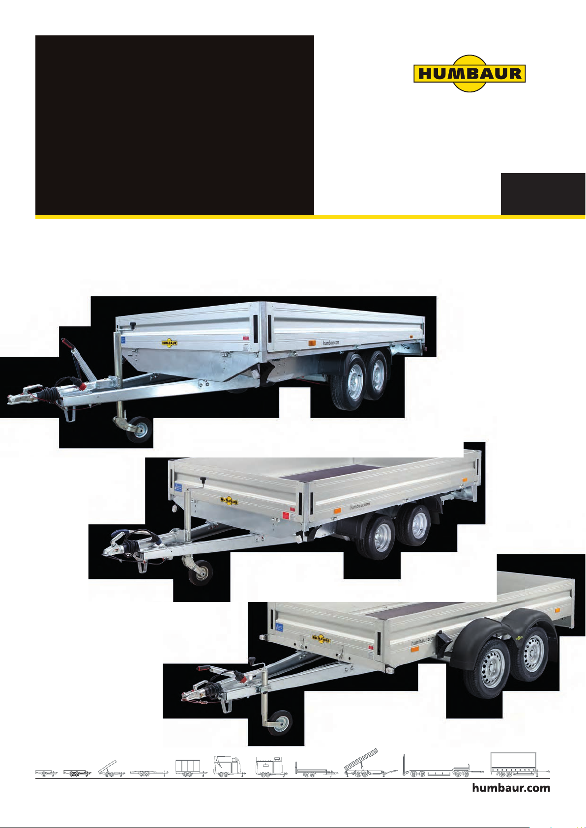
2 Product description
4
2.1 Components
Illustrated examples
HA
1
2
3
5
6 7 8
11 12 13
10
9
14 15
16
17
HT HN
14
15
16
Front view
HA
18
1. Cargo bed
2. Covered lock
3. Hand brake lever
4. Ball coupling
5. Safety cable
6. Drawbar support
7. Parking socket electric systems /
plug holder
8. Jockey wheel
9. V drawbar
10. Drop side hinge (HA)
11. Front drop side
12. Front reflector /
side light
13. Wheel chock
14. Mudguard
15. Wheel/tyre
16. Spray flap
17. Side reflector / yellow reflector
18. Side drop side
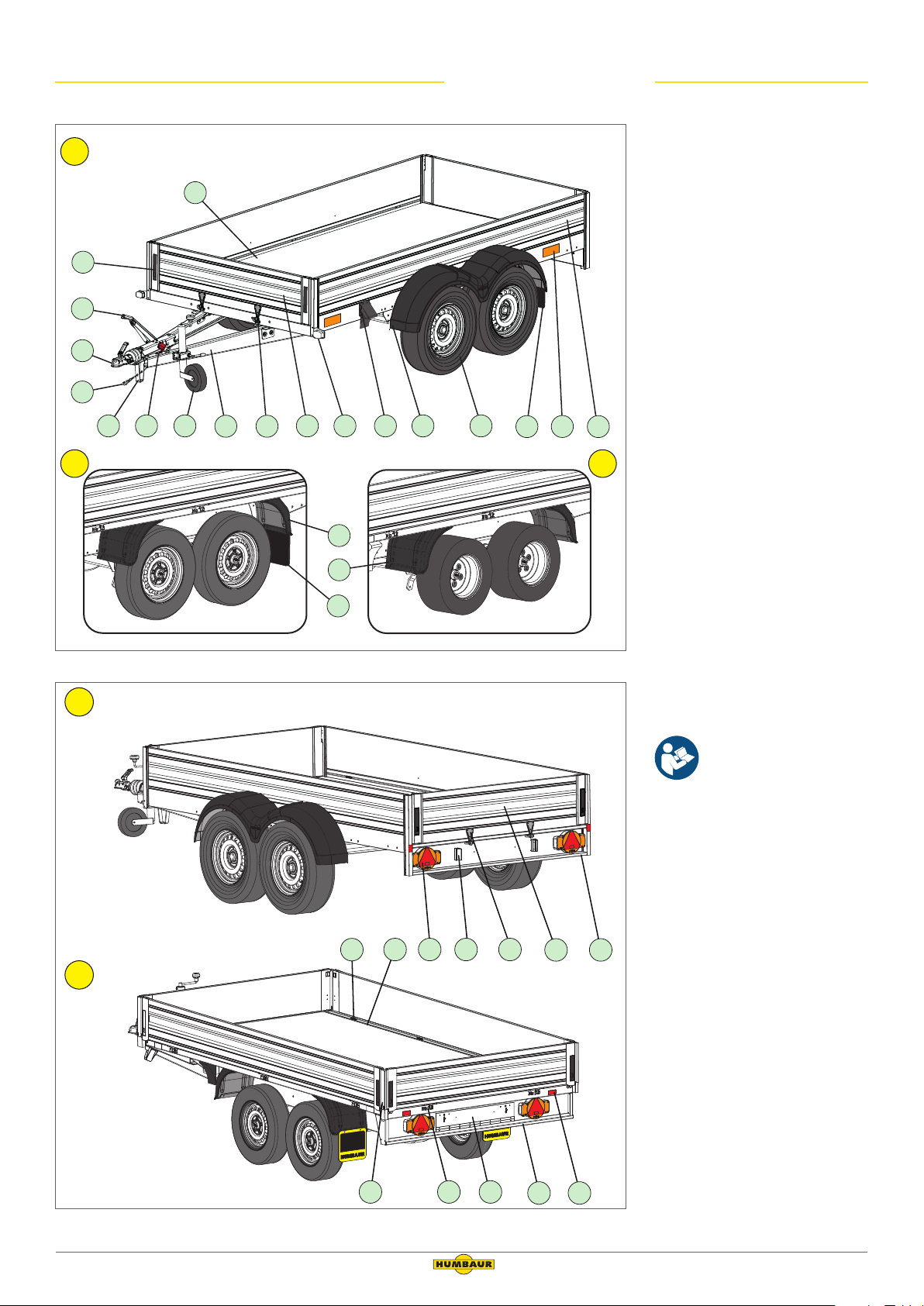
19. Tie-down point
20. V lashing rails
21. Tail light, combined with triangular reflector, indicator, brake
light, rear fog light, optional
reversing light, position lamp
22. Number plate light
23. Rear drop side
24. Underride protection
25. Stanchion
26. Drop side hinge (HN/HT)
27. Ramp slot
28. Rear reflector / red reflector
HT
19
20 22231021
Accessories/extensions are
separately explained in the
partial description below
or in the operating
instruction manual
“Trailers up to 3.5 to
General Points – Part 1.”
24
25
Rear view
Tandem HA, HN & HT Operating Instruction Manual (Part 2)
26 27
Version 2019/01 5
2824
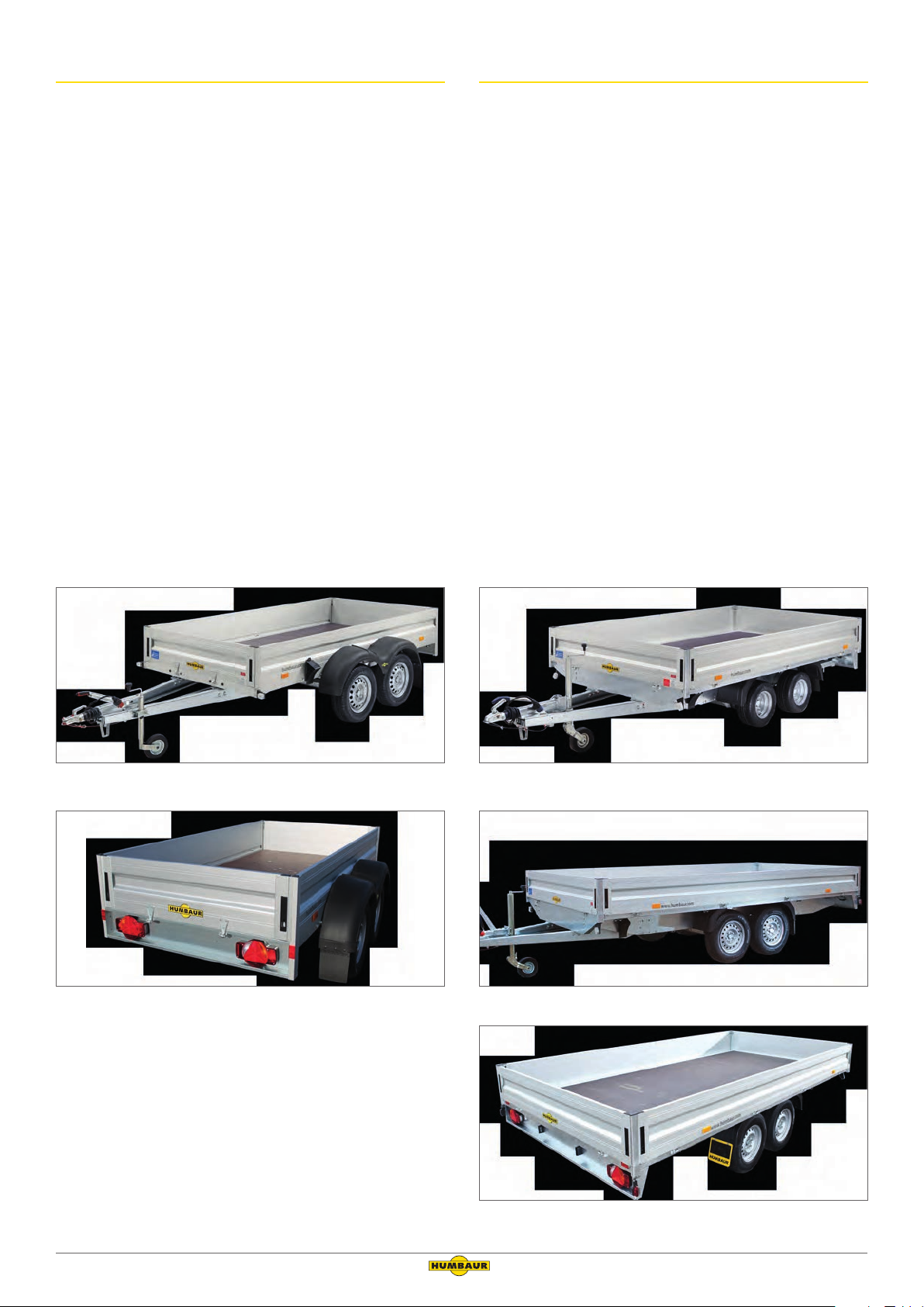
2.2 Flatbed trailers aluminium HA
2.3 Aluminium HN and HT wheels-in trailer
The HA is equipped with anodised aluminium drop sides.
The rear and side drop side can be folded down and removed.
The locks are recessed in the drop sides.
The 15-mm thick floor plate is made of multiple layers of laminated wood and an anti-slip coating.
The HA is available braked with 2000 kg and 2500 kg gross weight.
The HA permits a wide range of applications for payloads of up
to 2113 kg.
The load is secured with the aid of 6 tie-down brackets integrated into the side drop sides.
The tie-down brackets are Dekra-tested and allow a tractive force
of 400 daN (kg) per tie-down bracket.
The tyres have a standard size of 13" or 15" (inch).
The HN/HT is equipped with anodised aluminium drop sides.
All of the drop sides can be folded down and removed.
The locks are recessed in the drop sides.
The 18-mm thick floor plate is made of multiple layers of laminated wood and an anti-slip coating.
The load height with HN is lower than with HT due to the smaller
wheels.
HN
The HN is available braked with 2000 kg, 2500 kg and 3000 kg
gross weight.
The HN permits a wide range of applications for payloads of up
to 2495 kg.
The load is secured with the aid of 4 tie-down brackets recessed
into the V-profile of the trailer frame.
The tyres have a standard size of 10" (inch).
HT
The HT is available braked with 2000 kg, 2500 kg, 3000 kg 3500 kg
gross weight.
The HT permits a wide range of applications for payloads of up
to 2930 kg.
The load is secured with the aid of 4 tie-down brackets recessed
into the V-profile of the trailer frame.
The tyres have a standard size of 13" to 15" (inch).
HA front view
HA rear view
HN front view
HT front view
HT / HN rear view
6 Version 2019/01
Tandem HA, HN & HT Operating Instruction Manual (Part 2)
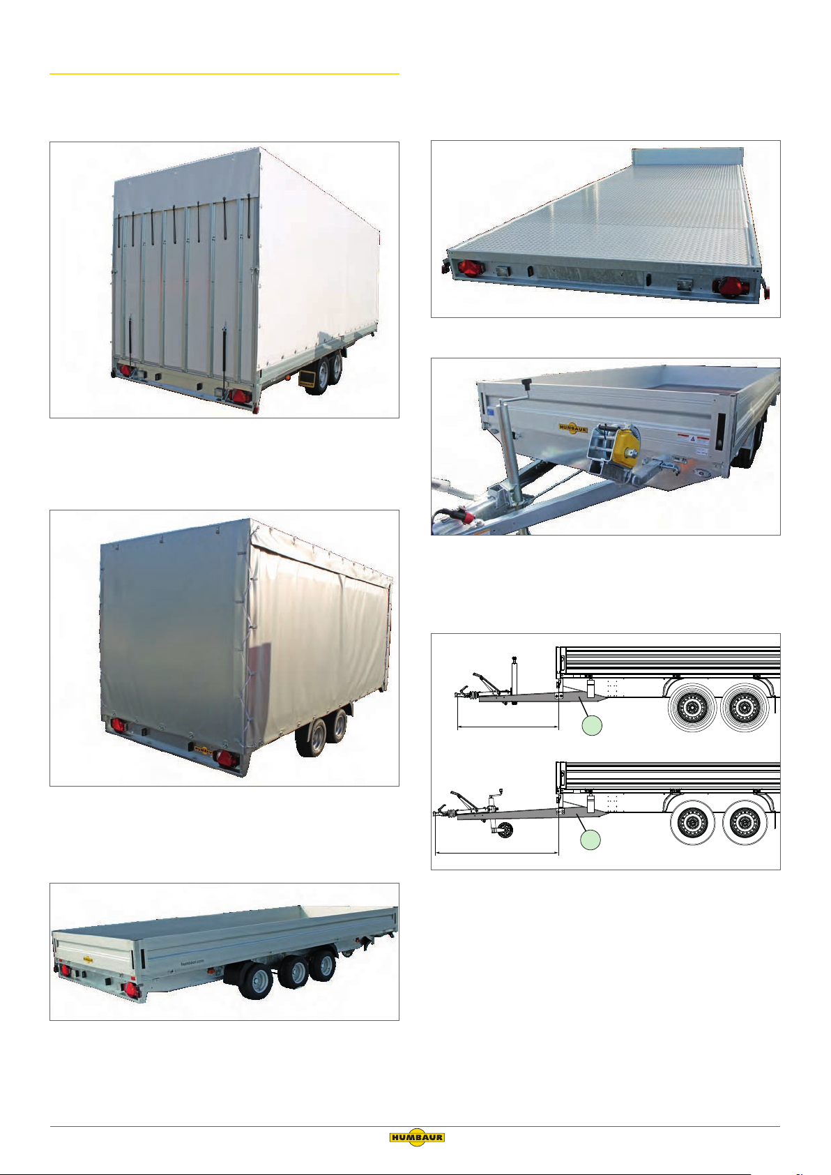
2.4 Special versions
1
2
Ramp wall with tarpaulin cover
Ramp wall rear view
Tarpaulin cover without drop sides
Vehicle transporters
HN with aluminium checker plate, rear view
Tarpaulin cover without drop side
3-axle trailer
HN with cable winch frame, front view
Long drawbar
1333
1621
HN / HT with long drawbar, side view
1. Standard drawbar
2. Long drawbar (288 mm longer)
3-axle trailer rear view
Tandem HA, HN & HT Operating Instruction Manual (Part 2)
Version 2019/01 7
2.5 Optional accessories
H-frame Side wall extension
Wood/aluminium cover Rail
Cover net Two-part drop side
Drawbar toolbox HN/HT toolbox
Drawbar spare wheel Side spare wheel
Prop stand Telescopic prop stand
Flat cover Tarpaulin + frame
Steel mesh extension Aluminium checker plate
Aluminium drive-up ramp Grid ramp wall
Lashing ring HV drawbar
8 Version 2019/01
Tandem HA, HN & HT Operating Instruction Manual (Part 2)
3 Intended use
• Transport of goods, with the exception of hazardous
goods, e.g., explosive, chemical or liquid materials.
• Transport of fixed and loose loads.
• Transport of long loads (e.g., square timber, profiles).
• Transport of materials and load materials as solid/packaged
load units, such as bricks on pallets.
• Load securing on the cargo bed with lashing brackets using
form and force load securing methods.
3.1 HA
• Transport of vehicles – only for version with grid ramp wall.
3.2 HN / HT
5 General safety instructions
Observe the other general safety recommendations in
the operating instruction manual, “Trailers up to 3.5 to”
(General Points – Part 1).
WARNING
Driving with folded down/unsecured
drop sides/side wall extensions.
Folded down/unsecured drop sides and side wall extensions may
be torn off and flung away while driving – risk of impact/crushing!
Folded down drop sides cover the vehicle lights/vehicle
markings – increased accident risk!
• Transport of large loads as a flat-bed variant, without drop
sides and stanchions.
• Transport of vehicles – only for version with drive-up ramp.
4 Foreseeable misuse
• Transport of persons and animals.
• Driving with insufficient load securing.
• Driving with an unsecured, projecting load.
• Driving with the wood/aluminium cover/drop sides not locked.
• Driving with side wall extensions/H-frame not bolted to
stanchions.
• Driving with support devices not retracted at the rear.
• Transport of inadequately secured vehicles.
• Non-observance of the safety instructions in the operating
instruction manual, “Trailers up to 3.5 to” (Part 1).
4.1 HA
• Overloading the grid ramp wall.
• Driving with unsecured grid ramp wall.
4.2 HN / HT
• Overloading the drive-up ramp.
• Driving as flat-bed without drop sides, but with inserted
stanchions.
►► Before driving off, check that all drop sides/side wall
extensions are closed and secured.
►► Remove all drop sides/side wall extensions/
stanchions when using the trailer as a flat-bed.
Loading/unloading bulk goods!
The bulk goods can press against the drop sides
during loading. Unsecured drop sides may spring
open, presenting a hitting/crushing risk!
►► Before loading bulk goods, make sure that all drop sides
are closed and secured.
►► Stand to one side when unlocking the drop sides – not
directly in front of it.
Materials on the trailer!
Materials such as snow/ice can be thrown on the road during
the journey – accident risk!
►► Remove ice and snow from the cargo bed/tarpaulin in
general and before driving off.
►► Check that there are no loose objects on the cargo bed/
tarpaulin before driving off.
Tandem HA, HN & HT Operating Instruction Manual (Part 2)
Loose objects on the cargo bed
Climbing on the tarpaulin is absolutely prohibited!
The operator accepts full responsibility if this is disregarded.
Version 2019/01 9

6 Loading and unloading
CAUTION
6.2.1 Loading/unloading the trailer
Folding ramp wall
After unlocking, the ramp wall can fall down
uncontrollably, e.g., from load pressure – impact
risk!
This can result in feet being crushed.
►► Stand to the side when unlocking the ramp wall.
►► Relieve the load pressure beforehand if necessary.
►► Allow the ramp wall to fall to the floor if the gas struts
are defective.
Never try to stop it.
►► Keep your feet away from the area around the
ramp wall.
►► Keep people away from the area around
the ramp wall during unfolding.
►► Use .
Walking on the mudguards is prohibited!
You can fall if you walk on the mudguards, since
the plastic mudguard gives way.
►► Do not climb on the mudguards.
The trailer must be secured so it cannot roll away.
►► Make sure that road traffic safety is not impaired
when loading and unloading the trailer.
►► If necessary, use additional signalling devices, e.g., signs,
barriers.
6.1 Load distribution
Before loading, check the max. load capacity that you
are able to transport with your trailer.
Check that the max. permissible body dimensions of
your trailer are not exceeded.
The load distribution works directly on the road handling of the
towing vehicle tension.
►► If necessary, use a stable access aid, e.g., a ladder or stool.
NOTICE
Poor/one-sided load distribution of the goods!
Strongly uneven/point load distribution can lead to
overstressing and damage to the trailer components.
►► Before loading your trailer, check which
load objects are the heaviest.
►► Position the heaviest objects centrally on
the cargo bed and in the area of the axles.
►► Distribute the goods evenly over the cargo bed
- Avoid point/one-sided load distribution.
10 Version 2019/01
Tandem HA, HN & HT Operating Instruction Manual (Part 2)
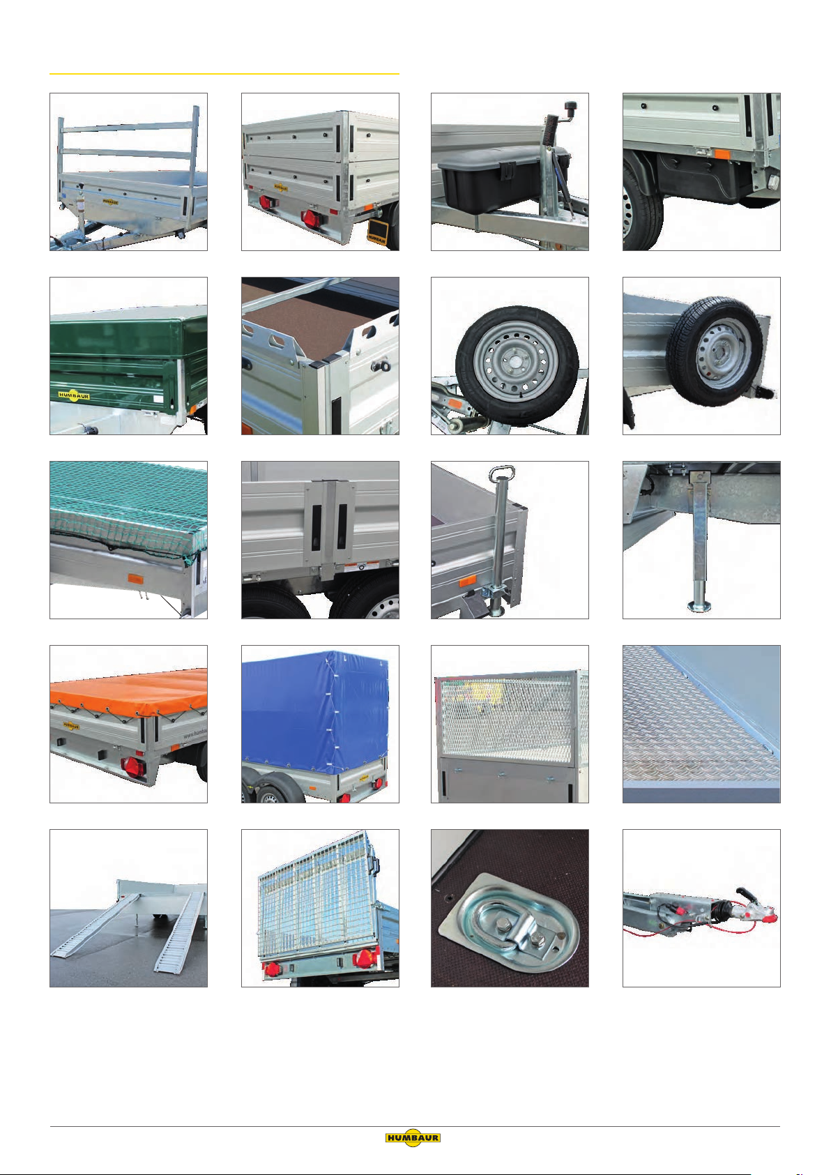
Correct load distribution
kg
Load in axle area
6.2 Load securing
For relevant safety information for load securing, refer to
the section “General load securing” in the operating
instruction manual “Trailers up to 3.5 to – General part 1.”
WARNING
Unsecured load!
The load can be thrown around during the journey. The trailer
may start to lurch – accident risk!
The trailer and the towing vehicle are stable with all wheels on
the ground.
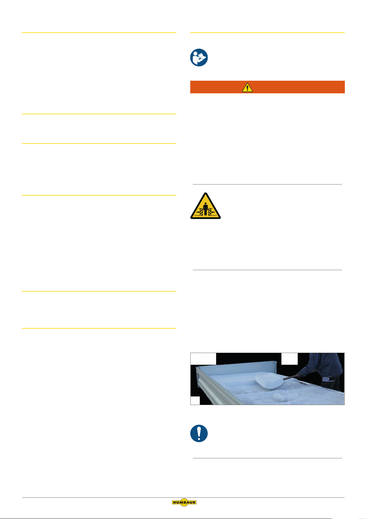
Incorrect load distribution
kg
Load too far forward (toward motor vehicle)
The trailer tilts forwards; the towing vehicle tilts backwards = the max.
drawbar load has been exceeded.
Incorrect load distribution
►► Make sure that the load is secured by form and force-fit-
ting before driving off.
►► If required, have tie-down points retrofitted.
►► Ideally, secure the load with a combination of form-fitting
and force-fitting:
- Force-fitted by: Direct tie-down of the load.
- Form-fitted by: Supporting the various components
of the load against each other, against the drop sides
and against the cargo bed extensions, without spaces
in-between.
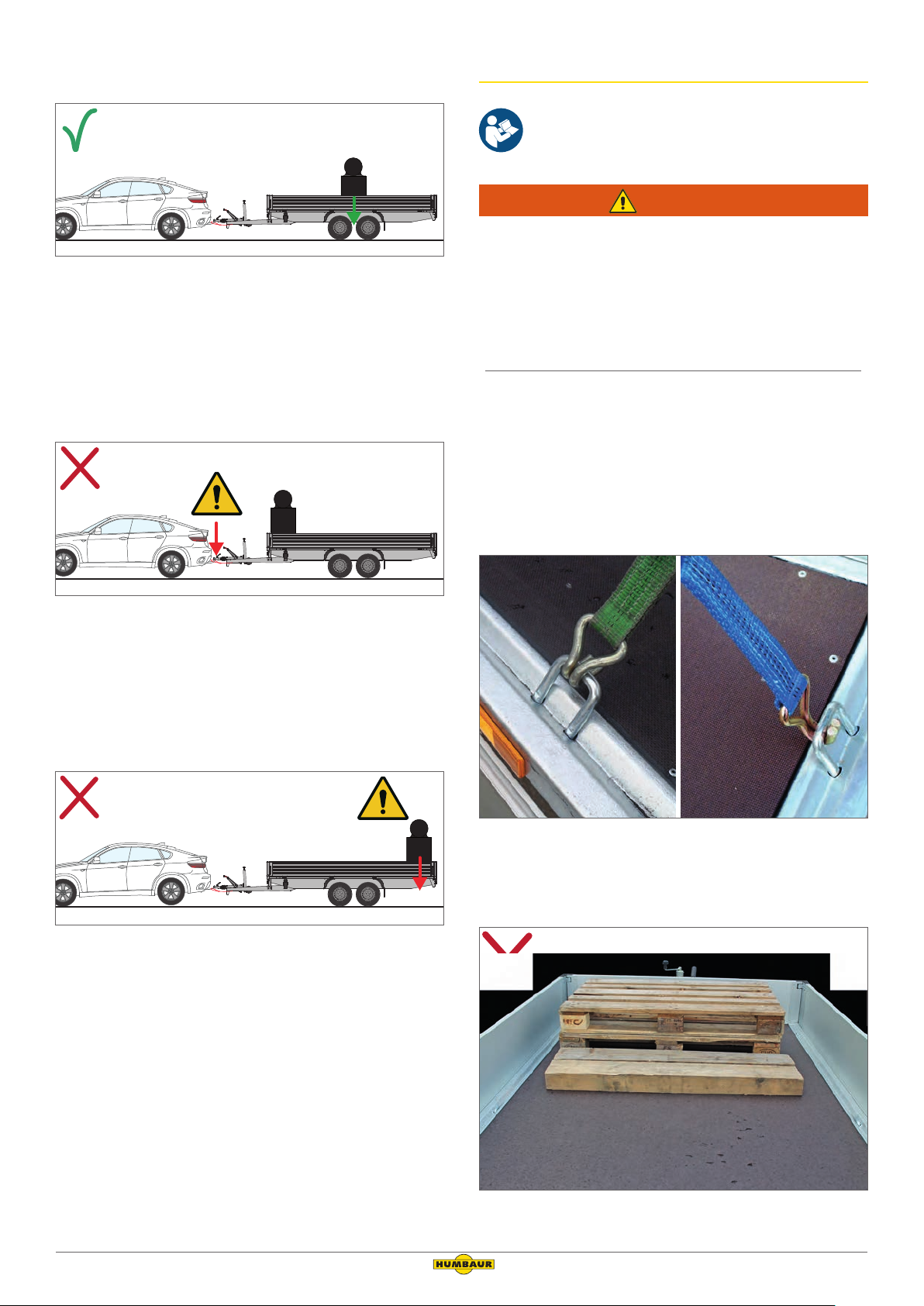
kg
Load too far backwards (from motor vehicle)
The trailer tilts backwards; the towing vehicle tilts forwards = the
drawbar load is too low or is negative.
Tandem HA, HN & HT Operating Instruction Manual (Part 2)
Tie-down options
The hook of the ties can be fastened to the tie-down bracket
from the inside or from the outside.
Loose load, not secured
Version 2019/01 11
Secured with tie-down
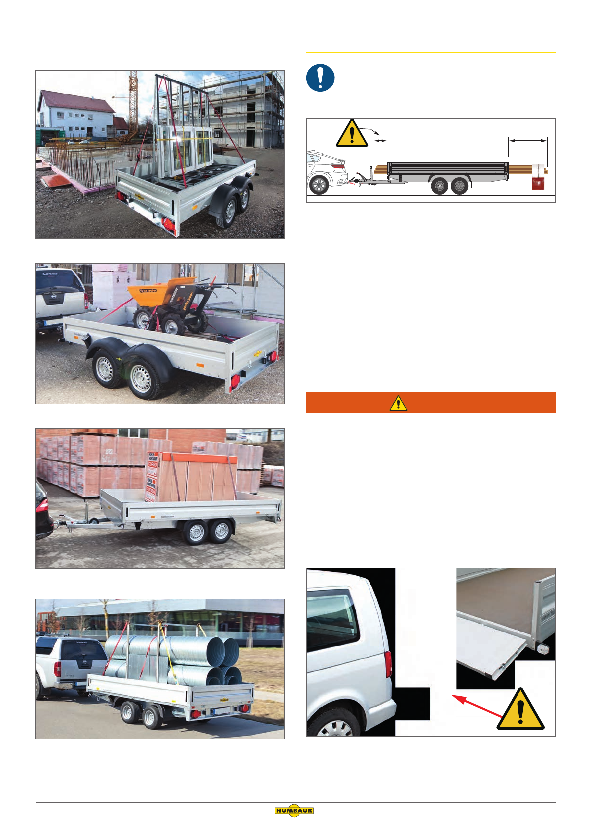
6.2.1 Projecting load
In Germany, goods that project over the cargo bed or
drop sides must be marked in accordance with
Section 22 of the StVO (German Road Traffic Act).
> 1 m
Marking goods
1. Sign/flag (30 cm x 30 cm) or cylindrical body (ø 35 cm x 30 cm),
bright red
►► Check that your load does not exceed the maximum
permissible values according to Section 22,
“Goods,” of the StVO.
►► Mark any projecting goods.
- Make use of the prescribed means for doing so.
►► Do not load the goods too far forward.
- The required swerving range for driving around bends
must remain open!
Secured with tie-down
Secured with tie-down
WARNING
Restricted swerving range – risk of collision!
Supporting the load on the front drop side and allowing it to
project forwards reduces the swerving range when driving
around bends – accident risk!
►► Before driving off, check that the restricted swerving
range will allow your towing vehicle to drive around
bends.
►► Adjust the distribution of the load towards the centre
between the drawbar if necessary.
►► If necessary, remove the front drop side.
Secured with form-fitting and tie-down
Driving with open front drop side
12 Version 2019/01
Tandem HA, HN & HT Operating Instruction Manual (Part 2)
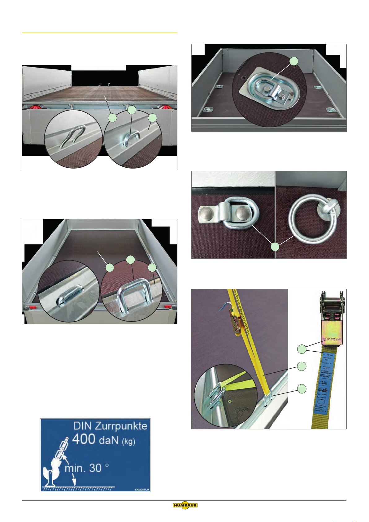
6.2.2 Tie-down points
2
Tying down goods
31
HA - tie-down points (tie-down force = max. 400 daN (kg))
1. Loading platform
2. Tie-down brackets, recessed
3. Side drop side
1
Optional/additional tie-down points
1. Tie-down ring recessed in tie-down groove, in loading platform
(tie-down force = max. 400 or 200 daN (kg))
2
1
HN/HT - tie-down points (tie-down force = max. 400 daN (kg))
1. Loading platform
2. Tie-down brackets, recessed
3. V-frame profile
3
►► Tie down the load.
- Do not exceed the maximum permissible tie-down
forces per tie-down point.
►► Take note of the sticker providing information about the
maximum tie-down forces on the trailer.
1
Optional/additional tie-down points
1. Folding rings on the loading platform
3
2
1
Tie-down of load
1. Tie-down point
2. Tie-down equipment (tension belt)
3. Tie-down force information
►► Adhere to the maximum tie-down force for the tie-down
Tandem HA, HN & HT Operating Instruction Manual (Part 2)
equipment (e.g., tension belts).
Version 2019/01 13
6.3 Drop sides
WARNING
NOTICE
WARNING
1
3
4
5
6
Driving with the rear drop side folded down!
Any rear lights are covered. The trailer cannot be seen in
traffic – danger of accident!
►► Remove the rear drop side when driving with a load
projecting to the rear.
Driving with the front drop side folded down!
The front drop side is not secured and can move while
driving – risk of material damage!
►► Remove the front drop side when driving with a load
projecting to the front.
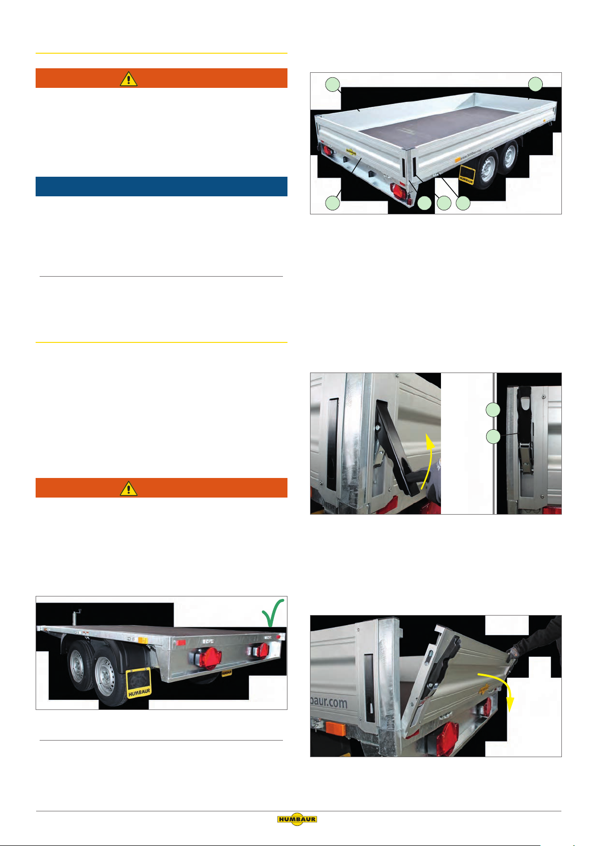
6.3.1 Drop side – HN / HT
Functional explanation
• The 4 drop sides can be folded down, depending on the
loading/unloading process.
• The drop sides can be removed in order to transport longer
and wider cargo.
• The stanchions are secured by the closed drop sides to
prevent them from falling out.
• The stanchions can be removed when the drop sides are
removed.
2
Drop sides and stanchions fitted
1. Side drop side
2. Front drop side
3. Rear drop side
4. Stanchion
5. Covered lock
6. Drop side hinge
Opening
1
2
Driving as flat-bed with stanchions inserted!
The stanchions may be flung out while driving and hit
people – risk of accident/impact!
►► Remove all drop sides before starting to drive.
►► Remove all stanchions before starting to drive.
Driving as flat-bed (drop sides/stanchions removed)
Unlocking locks
1. Drop side
2. Covered lock
►► Unlock the recessed locks on both sides.
- While doing so, hold the drop side with one hand.
Folding down the rear drop side
►► Carefully fold down the drop side in a controlled manner.
14 Version 2019/01
Tandem HA, HN & HT Operating Instruction Manual (Part 2)
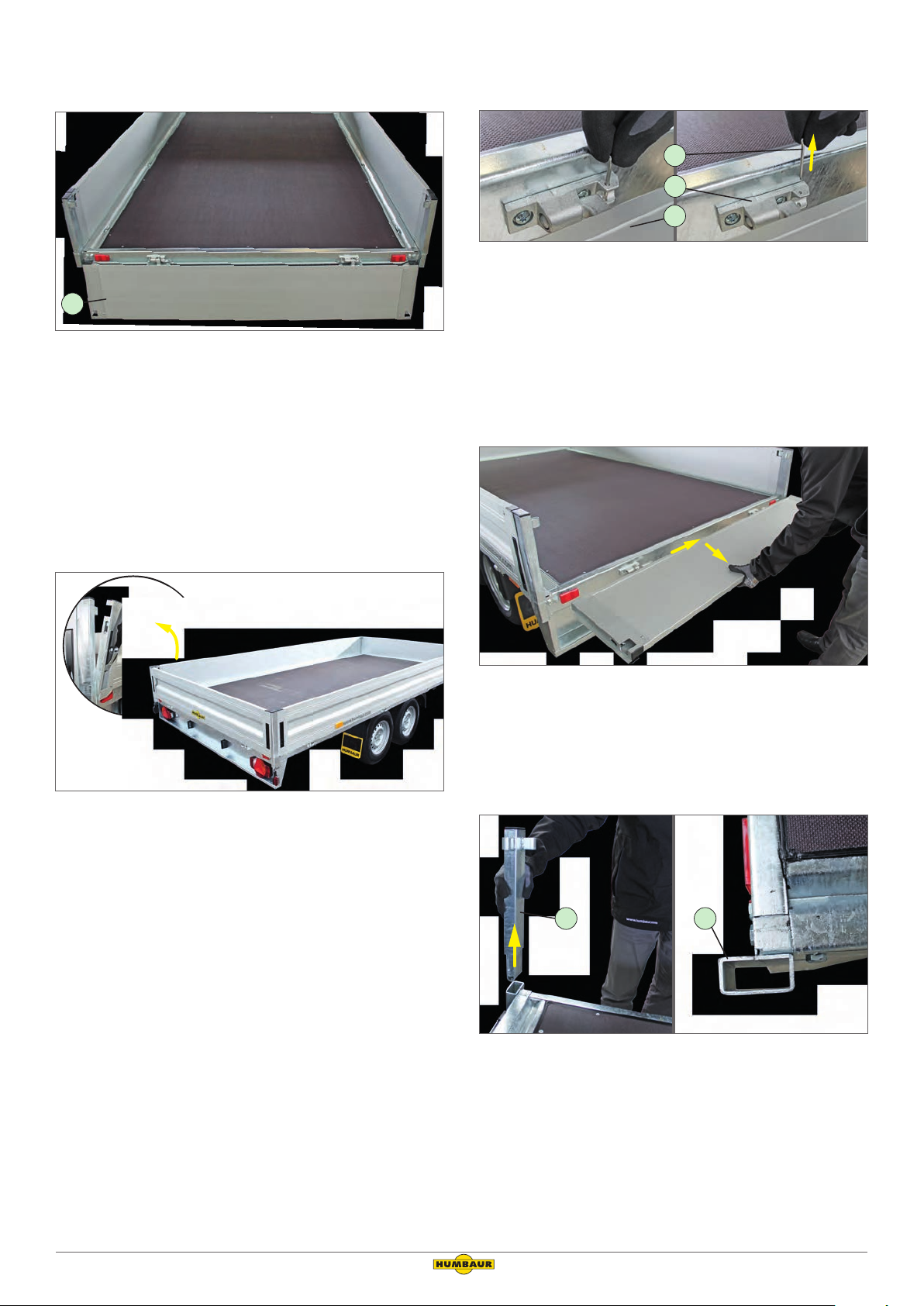
Taking off the drop side
2
Drop side hinge release
1
3
1
Rear drop side, folded down
1. Rear drop side, folded down
Closing
1. Securing split pin
2. Drop side hinge
3. Drop side
►► Remove the securing split pin from the drop side hinge.
►► Hold the drop side in about the middle lengthwise.
►► Fold the drop side to a horizontal position.
Taking off the drop side
►► Carefully pull out the drop side in the direction that is
now unobstructed.
►► Put the drop side where it is safe from damage.
Closing the drop sides
►► Open the covered locks as required.
►► Fold up the drop side.
►► Lock all locks on the drop side.
While doing so, hold the drop side with one hand.
- Ensure that they correctly engage with the locking lugs
of the stanchions.
1 2
Removing stanchion removed
1. Stanchion
2. Stanchion pocket
►► Pull the stanchions out of the stanchion pockets.
If the stanchions are stuck:
►► Release them by carefully tapping the side with a soft-
head hammer.
Tandem HA, HN & HT Operating Instruction Manual (Part 2)
Version 2019/01 15
 Loading...