

Page 1

**
**
**
**
**
**
**
TABLE OF CONTENTS
**
Introduction .......................................................................**2
**
Safety Information:
Important Safety Information .............................................. 3
Unpacking ...........................................................................**3
**
Front Panel Controls .......................................................**4
**
Front Panel Information Display ....................................**6
**
Rear Panel Connections .................................................**7
**
Main Remote Control Functions ....................................**9
**
Installation and Connections:
System Installation ............................................................ 12
System and Power Connections .......................................**13
**
System Configuration:
Speaker Placement ........................................................... 14
System Setup .................................................................... 15
Speaker Optimizer ............................................................. 16
Setting System Configuration Memory .............................. 16
Input Setup ........................................................................ 16
Surround Setup ................................................................. 17
Speaker Setup ................................................................... 18
Delay Settings ................................................................... 20
Output Level Adjustment ................................................... 21
Additional Input Adjustments .............................................**22
**
Operation:
Basic Operation ................................................................. 23
Turning the AVE-750 On or Off ......................................... 23
Remote Control Operation ................................................ 23
Source Selection ............................................................... 23
Volume Control ................................................................. 24
Surround Mode Selection .................................................. 24
Surround Mode Chart ........................................................ 25
Digital Audio Playback ...................................................... 26
Selecting a Digital Source ................................................. 26
Digital Status Indicators ..................................................... 26
Night Mode ........................................................................ 27
PCM Audio Playback ......................................................... 27
MP3 Audio Playback .........................................................**27
**
Tuner Operation ...................................................................... 27
Station Selection ..................................................................... 27
Preset Tuning ......................................................................... 28
Recalling Preset Stations ....................................................... 28
RDS Operation ....................................................................... 28
Recording ............................................................................... 28
Front Panel Connections ........................................................ 29
Output Level Trim Adjustment ................................................ 29
6/8-Channel Direct Input .........................................................**29
Advanced Features:
Display Brightness .................................................................. 30
Turn-On Volume Level ............................................................ 30
OSD Settings .......................................................................... 30
Semi-OSD Settings ................................................................. 30
Full-OSD Time-Out Adjustment ..............................................**31
Configuring the Remote:
Changing Devices ................................................................... 32
Resetting the Remote ..............................................................**32
Troubleshooting Guide:
Processor Reset ......................................................................**33
AVE-750 Technical Specifications .......................................**34
Trademark acknowledgements ............................................**35
Appendix:
DVD Code List .......................................................................... 36
CD Code List ............................................................................ 37
TAPE Code List ........................................................................ 39
VCR Code List ......................................................................... 40
TV Code List ............................................................................ 42
CABLE Code List ..................................................................... 45
**
**
**
**
**
**
**
**
**
**
**
**
**
TABLE OF CONTENTS 1
**
**
Page 2
**
**
**
**
**
**
1 INTRODUCTION
**
Thank you for choosing HUMAX! With the purchase of a HUMAX
AVE-750 you are about to begin many years of listening enjoyment.
Designed to provide all the excitement and detail of movie
soundtracks and every nuance of musical selections, the AVE-750
is truly a multi-channel receiver for the new millennium.
The AVE-750 has been engineered so that it is easy to take
advantage of all the power of its digital technology. On-screen
menus, a fully programmable remote control, fully color-coded
connection jacks and terminals make installation fast and simple.
However, to obtain the maximum enjoyment from your new
receiver, we urge you to read this manual. A few minutes spent
learning the functions of the various controls will enable you to take
advantage of all the power the AVE-750 is able to deliver.
If you have any questions about this product, its installation or its
operation, please contact your retailer or installer. They are your
best local sources of information.
**
Description and Features
The AVE-750 is one of the first fully featured A/V receivers to use
PWM digital amplifier technology in a high-performance audio/video
receiver. A fully digital path from source input to the output stage
eliminates the need for digital-to-analog conversion before
amplification. This reduces the possibility of signal degradation or
the introduction of distortion. Digital technology also enables
HUMAX to provide seven amplifier channels, while reducing the
size and weight of the chassis to a slimmer profile.
The AVE-750 is among the most versatile and multifeatured A/V
receivers available, incorporating a wide range of listening options.
In addition to Dolby* Digital, Dolby Digital EX and DTS
for digital sources, a broad choice of surround modes is available
for use with PCM digital and analog sources such as CD, VCR, TV
broadcasts and the AVE-750’s own AM/FM tuner.
The AVE-750 offers a wide range of sound mode; Dolby Pro Logic*
II, DTS Neo: 6
AVE-750 is among the few A/V receivers that offer MP3 decoding,
so that you may listen to the latest music selections directly from
compatible computers or playback devices.
In addition to providing a wide range of listening options, the
AVE-750 is easy to configure so that it provides the best results
with your speakers and specific listening-room environment.
**
For the ultimate in flexibility, the AVE-750 features connections for
four video devices, all with both composite and S-Video inputs. Two
additional audio inputs are available, and a total of six digital inputs
make the AVE-750 capable of handling all the latest digital audio
sources. For compatibility with the latest HDTV video sources and
progressive scan DVD players, the AVE-750 also features
high-bandwidth, low-crosstalk component video switching.
Coax and optical digital outputs are available for direct connection
to digital recorders, and both the front panel analog audio/video and
coaxial digital jacks may be switched to outputs for use with
portable recorders. A video recording output, preamp-out jacks, and
a color-coded eight-channel input make the AVE-750 virtually
future-proof.
, Dolby 3 Stereo, Hall and many others. Finally, the
decoding
**
**
Digital amplifiers provide seven channels of high-performance
■
sound in a compact cabinet without the need for noisy cooling
fans
Dolby* Digital EX 6.1 and Dolby Pro Logic* II decoding, and a
■
wide range of DTS
Matrix and Neo:6,
MP3 decoding for use with many computers and digital audio
■
players
High-bandwidth, HDTV-compatible component video switching
■
Front panel digital inputs and coax digital output capability for
■
easy connection to portable digital devices and the latest video
game consoles
Multiple digital inputs and outputs
■
Front panel analog A/V and coax digital jacks switchable to
■
outputs for easy connection to portable digital devices or video
game consoles
On-screen menu and display system
■
modes, including DTS-ES 6.1 Discrete &
using a 24-bit Cirrus DSP engine
**
CAUTION
RISK OF ELECTRIC SHOCK
DO NOT OPEN
CAUTION: To prevent electric shock,
do not use this (polarized)plug with
an extension cord, receptacle or
other outlet unless the blades can be
fully inserted to prevent blade
exposure.
The lightningflash with arrowhead symbol,
within an equilateral triangle, is intended to alert
the user to the presence of uninsulated
“dangerous voltage” within the product’s
enclosure that may be of sufficient magnitude to
constitute a risk of electric shock to persons.
The exclamation point within an equilateral
triangle is intended to alert the user to the
presence of important operating and
maintenance (servicing) instructions in the
literature accompanying the appliance.
**
**
**
**
**
INTRODUCTION 2
**
**
**
**
Page 3

**
**
**
**
**
**
2 SAFETY INFORMATION
**
Important Safety Information
**
Verify Line Voltage Before Use
Your AVE-750 has been designed for use with 230-volt AC current.
Connection to a line voltage other than that for which it is intended
can create a safety and fire hazard and may damage the unit.
If you have any questions about the voltage requirements for your
specific model, or about the line voltage in your area, contact your
selling dealer before plugging the unit into a wall outlet.
**
Do Not Use Extension Cords
To avoid safety hazards, use only the power cord attached to your
unit. We do not recommend that extension cords be used with this
product. As with all electrical devices, do not run power cords under
rugs or carpets or place heavy objects on them. Damaged power
cords should be replaced immediately by an authorized service
center with a cord meeting factory specifications.
**
Handle the AC Power Cord Gently
When disconnecting the power cord from an AC outlet, always pull
the plug; never pull the cord. If you do not intend to use the unit for
any considerable length of time, disconnect the plug from the AC
outlet.
**
Do Not Open the Cabinet
There are no user-serviceable components inside this product.
Opening the cabinet may present a shock hazard, and any
modification to the product will void your guarantee. If water or any
metal object such as a paper clip, wire or a staple accidentally falls
inside the unit, disconnect it from the AC power source immediately,
and consult an authorized service station.
**
Installation Location
**
To ensure proper operation and to avoid the potential for safety
■
hazards, place the unit on a firm and level surface. When
placing the unit on a shelf, be certain that the shelf and any
mounting hardware can support the weight of the product.
Make certain that proper space is provided both above and
■
below the unit for ventilation. If this product will be installed in a
cabinet or other enclosed area, make certain that there is
sufficient air movement within the cabinet. Under some
circumstances a fan may be required.
Do not place the unit directly on a carpeted surface.
■
Avoid installation in extremely hot or cold locations, or in an
■
area that is exposed to direct sunlight or heating equipment.
Avoid moist or humid locations.
■
Do not obstruct the ventilation slots on the top of the unit, or
■
place objects directly over them.
There is the remote possibility that the rubber padding on the
■
bottom of the unit’s feet may leave marks on certain wood or
veneer materials. Use caution when placing the unit on soft
woods or other materials that may be damaged by heat or
heavy objects.
The appartus shall not be exposed to dripping or splashing and
■
no object filled with liquids, such as vases, shall be placed on
the apparatus.
**
**
Cleaning
When the unit gets dirty, wipe it with a clean, soft, dry cloth. If
necessary, wipe it with a soft cloth dampened with mild soapy
water, then a fresh cloth with clean water.
Wipe dry immediately with a dry cloth. NEVER use benzene,
aerosol cleaners, thinner, alcohol or any other volatile cleaning
agent. Do not use abrasive cleaners, as they may damage the
finish of metal parts. Avoid spraying insecticide near the unit.
**
Moving the Unit
Before moving the unit, be certain to disconnect any interconnection
cords with other components, and make certain that you disconnect
the unit from the AC outlet.
**
Important Information for the User
This equipment has been tested and found to comply with the limits
for a Class-B digital device, pursuant to Part 15 of the FCC Rules.
The limits are designed to provide reasonable protection against
harmful interference in a residential installation. This equipment
generates, uses and can radiate radio-frequency energy and, if not
installed and used in accordance with the instructions, may cause
harmful interference to radio communication. However, there is no
guarantee that harmful interference will not occur in a particular
installation. If this equipment does cause harmful interference to
radio or television reception, which can be determined by turning
the equipment off and on, the user is encouraged to try to correct
the interference by one or more of the following measures:
Reorient or relocate the receiving antenna.
■
Increase the separation between the equipment and receiver.
■
Connect the equipment into an outlet on a circuit different from
■
that to which the receiver is connected.
Consult the dealer or an experienced radio/TV technician for
■
help.
**
This device complies with Part 15 of the FCC Rules. Operation is
subject to the following two conditions: (1) this device may not
cause harmful interference, and (2) this device must accept
interference received, including interference that may cause
undesired operation.
NOTE: Changes or modifications may cause this unit to fail to
comply with Part 15 of the FCC Rules and may void the user’s
authority to operate the equipment.
**
Unpacking
**
The carton and shipping materials used to protect your new
receiver during shipment were specially designed to cushion it from
shock and vibration. We suggest that you save the carton and
packing materials for use in shipping if you move, or should the unit
ever need repair.
If you do not wish to save the packaging materials, please note that
the carton and other sections of the shipping protection are
recyclable. Please respect the environment and discard those
materials at a local recycling center.
At this time you should also remove the protective plastic film from
the front panel lens. Leaving the film in place may affect the
performance of your remote control.
**
**
**
**
**
**
**
SAFETY INFORMATION 3
**
**
Page 4
**
**
**
**
**
3 FRONT PANEL CONTROLS
**
**
**
**
**
**
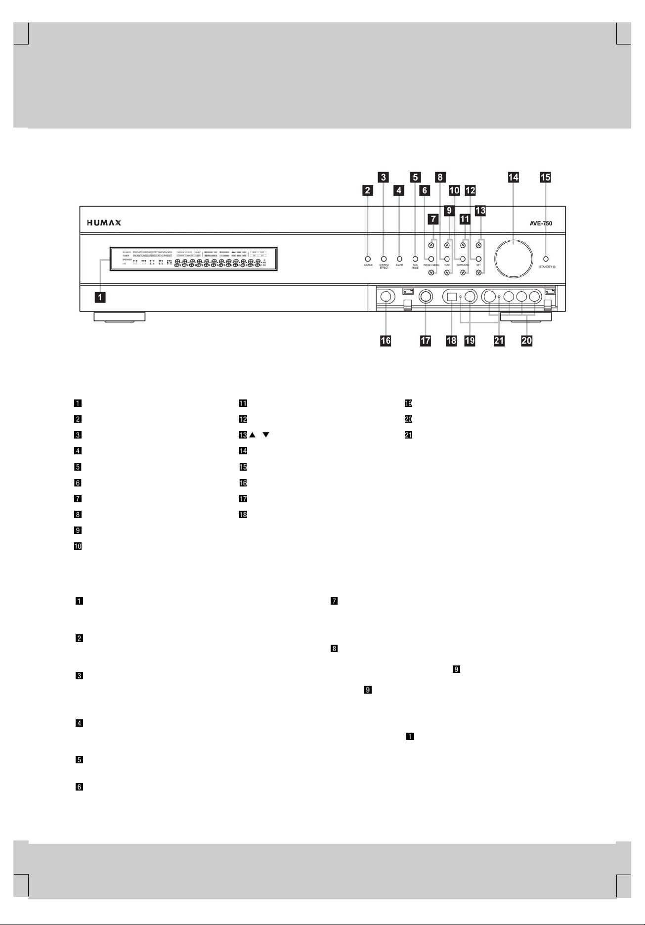
Main Information Display
Input Source Selector
Stereo/Effect Selector
AM/FM Selector
RDS Mode Selector
Preset Station Memory Button
Preset Station Selector
Tuning Mode Selector
Tuning Selector
Surround Mode Selector
**
Main Information Display: This display delivers messages and
status indications to help you operate the receiver.
**
Input Source Selector: Press this button to change the input
through the list of input sources.
**
Stereo/Effect Selector: Press this button to toggle between the
stereo sound and the various surround effect. If surround is off, it
doesn’t work.
**
AM/FM Selector: Pressing this button will automatically switch
the AVE-750 to the Tuner mode. Pressing it again will switch
between the AM and FM frequency bands.
RDS Mode Selector: Press this button to select RDS mode.
**
Preset Station Memory Button: Press this button to enter the
current tuner frequency into the preset station list.
Surround Select Button
Set Button
/ Button
Volume Control
STANDBY Button
Main Power Switch
Headphone Jack
Digital Optical 3 Input
Digital Coax 3 Jack
Video 3 Input/Output Jacks
Input/Output Status Indicators
Preset Station Selector: Press this button to scroll up or down
through the list or stations that have been entered into the preset
memory.
**
Tuning Mode Selector: This button is used to switch back and
forth between the auto and manual tuning modes. In auto mode,
you may use the Tuning Selector
an acceptable signal. In manual mode, you may use the Tuning
Selector
This button is also used to switch between stereo and mono modes
for FM radio reception. When weak reception is encountered, press
the button so that STEREO Indicator disappears in the Main
Information Display
to switch back to stereo mode.
**
to step through one frequency increment at a time.
to switch to the mono mode. Press it again
to scan through stations with
**
**
**
FRONT PANEL CONTROLS 4
**
**
**
**
Page 5

**
**
**
**
**
**
3 FRONT PANEL CONTROLS
**
Tuning Selector: Press the down side of the button to tune
lower-frequency stations and the upper side of the button to tune
higher-frequency stations.
In manual tuning mode, tap the button lightly and the tuner will step
up one frequency increment per button press. When the button is
held for a few seconds, the unit will quickly advance through the
frequency band. Release it and the tuner will stop. In auto tuning
mode, each press of the button will search for the next station with
an acceptable signal. Press and hold the button to skip through the
acceptable stations. When the button is released, the tuner will not
stop until it reaches a station with an acceptable signal.
To switch back and forth between the auto and manual tuning
modes, press the Tuning Mode Selector
**
Surround Mode Selector: Press this button to choose a
surround processing format category by scrolling through the list of
available formats as indicated in the Surround Mode Indicators
of Main Information Display . These format categories are:
Dolby surround modes, DTS Surround Modes. DSP modes and
Stereo modes. Once you have selected a format category, use the
Surround Select Button
overall category.
to choose a specific mode within the
**
Surround Selector Button: After choosing a surround
processing format category by using the Surround Mode Selector
, press this button to scroll through the list of available modes for
that format category.
**
Set Button: Press this button to access the configuration menus
for Test Tone, Speakers Channel Trim, Digital Input Select or
Delay. After pressing the button, use the
the desired menu.
**
/ Buttons Use this button to scroll through the System
Configuration modes indicated on the front panel: i.e., Test Tone,
Speaker, Channel, Digital Select and Delay. Press the Set Button
to select a configuration mode, and use this button to scroll
through the available adjustments for each System Configuration
mode.
**
Volume Control: Turn this knob clockwise to increase the
volume, counterclockwise to decrease the volume. If the AVE-750
is muted, adjusting the volume control will automatically release the
unit from the silenced condition.
**
STANDBY Button: When the Main Power Switch is “ON,”
press this button to turn on the AVE-750; press it again to turn the
unit off.
NOTE: The Main Power Switch
button will operate.
must be turned on before this
**
Main Power Switch: Press this button in to apply power to the
AVE-750. When the switch is pressed in, the unit is placed in a
Standby mode. This button must be pressed in to operate the unit.
To turn the unit off and prevent the use of the remote control, this
switch should be pressed until it pops out from the front panel.
NOTE: This switch is normally left in the “ON” position.
**
.
/ Buttons to select
**
Headphone Jack: This jack may be used to listen to the
AVE-750’s output through a pair of headphones. Be certain that the
headphones have a standard 1/4" stereo phone plug. The speakers
will automatically be turned off when the headphone jack is in use.
**
Digital Optical 3 Input: Connect the optical digital audio output
of an audio or video product to this jack.
**
Digital Coax 3 Jack: This jack is normally used for connection to
the output of portable audio devices, video game consoles or other
products that have a coax digital audio jack. It may also be
configured as an output jack, to feed a digital signal to a CD-R,
MiniDisc or other digital recording device.
**
Video 3 Input/Output Jacks: These audio/video jacks may be
used for temporary connection to video games or portable
audio/video products such as camcorders and portable audio
players. These jacks may also be configured as an output to feed
an analog audio/video signal to a VCR, camcorder, tape deck or
other recording device.
**
Input/Output Status Indicators: These LED indicators will
normally light green to show that the front panel Digital Coax 3
Jack
or Video 3 Input/Output Jacks are operating as inputs.
When either of these jacks has been configured for use as an
output, the indicator will turn red to show that the jack may be used
for recording.
**
**
**
**
**
**
**
FRONT PANEL CONTROLS 5
**
**
Page 6
**
**
**
**
**
**
4 FRONT PANEL INFORMATION DISPLAY
**
**
**
**
**
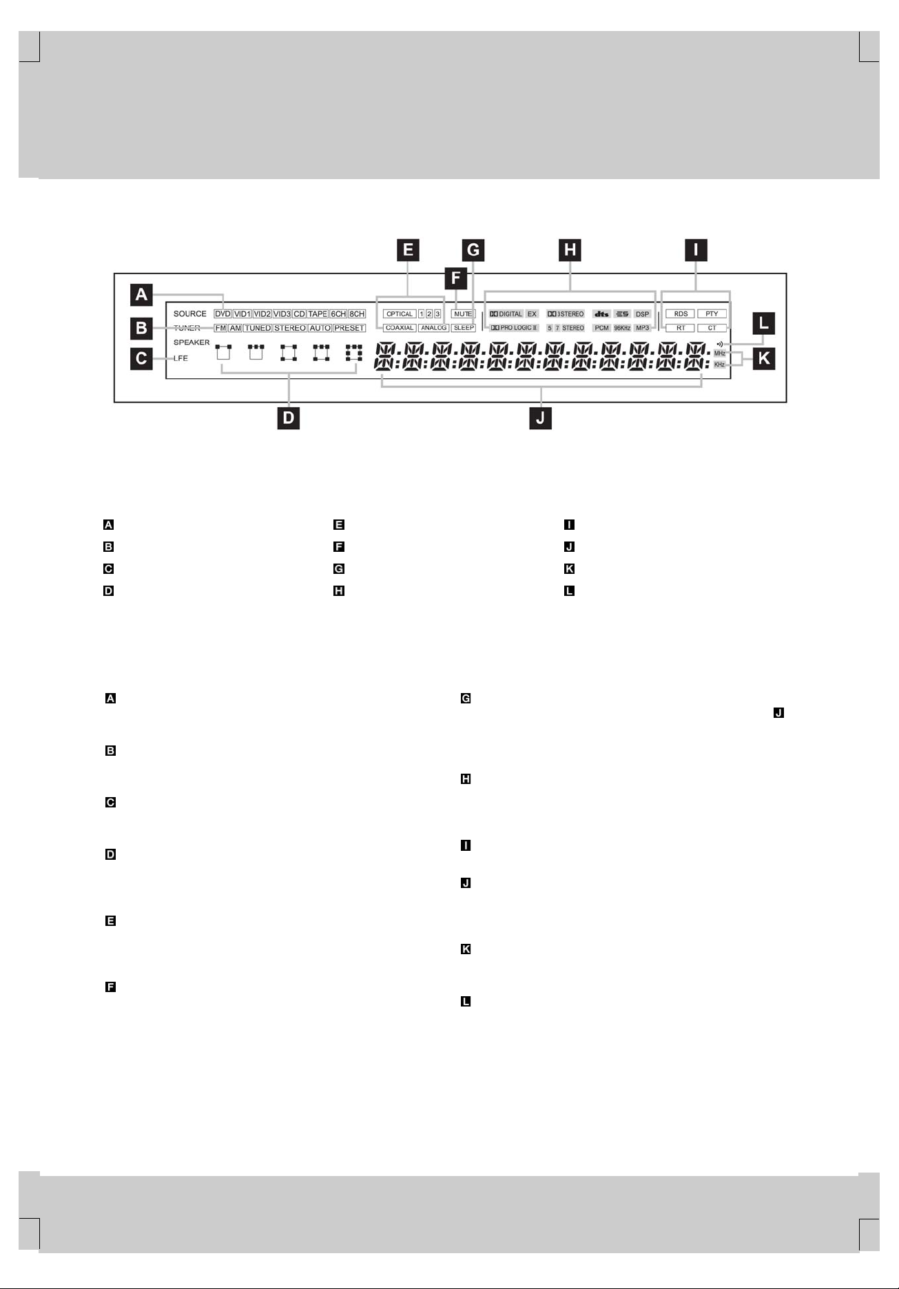
Input Indicators
AM/FM Tuner Status Indicators
Subwoofer Indicator
Speaker/Channel Input Indicators
Audio Input Indicators
Mute Indicator
Sleep Indicator
Surround Mode/Bitstream Indicators
**
Input Indicators: Indicate an input that is currently the input
source for the AVE-750.
**
AM/FM Tuner Status Indicators: Show the various information
related with tuner.
**
Subwoofer Indicator: Indicates that subwoofer (LFE; low
frequency effect) channel is active now.
**
Speaker/Channel Input Indicators: These indicators are
multipurpose, indicating either the speaker type selected for each
channel or the number of channels available from the input source.
**
Audio Input Indicators: Indicate whether the current audio
source comes from a digital input(optical/coaxial) or an analog
input.
**
Mute Indicator: Indicates that volume mute is active now.
RDS Mode Indicators
Display Line
Tuner frequency Indicators
Remote Control Detect Indicator
**
Sleep Indicator: This indicator illuminates when the sleep
function is in use. The number that appears in the Display Line
is the number of minutes remaining before the AVE-750 will return
to the Standby mode.
**
Surround Mode/Bitstream Indicators: Indicate the surround
mode that is currently in use and/or the type of digital data signal in
use.
**
RDS Mode Indicators: Indicate the current RDS mode selected.
**
Display Line: Depending on the receiver’s status, a variety of
messages will appear here. In normal operation, the current
surround mode name will appear on this line.
**
Tuner frequency Indicators: Indicates the unit of tuner
frequency.
**
Remote Control Detect Indicator: Blinks when the remote
control signal is detected by AVE-750.
**
**
FRONT PANEL INFORMATION DISPLAY 6
**
**
**
**
Page 7
**
**
**
**
**
5 REAR PANEL CONNECTIONS
**
**
**
**
**
**
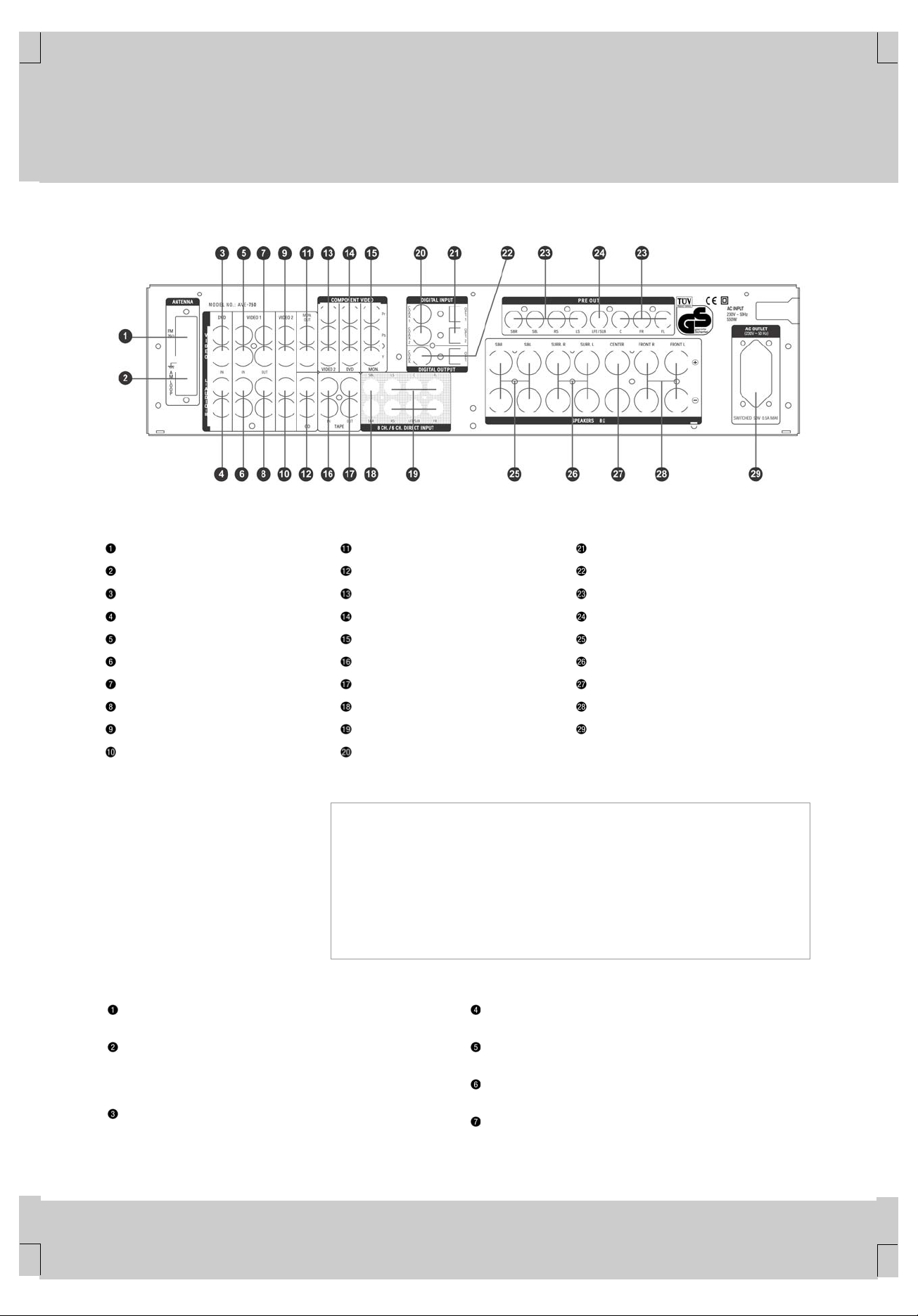
FM Antenna
AM Antenna
DVD Video Inputs
DVD Audio Inputs
Video1 Video Inputs
Video1 Audio Inputs
Video1 Video Outputs
Video1 Audio Outputs
Video2 Video Inputs
Video2 Audio Inputs
**
To assist you in making the correct
connections for multichannel input,
output and speaker connections, all
connection jacks and terminals have
been colorcoded in conformance
with the CEA standards as follows:
Video Monitor Outputs
CD Inputs
Video2 Component Video Inputs
DVD Component Video Inputs
Video Monitor Component Video Outputs
Tape Inputs
Tape Outputs
8-Channel Direct Inputs
6-Channel Direct Inputs
Coaxial Digital Audio Inputs
**
Front Left: White
•
Front Right: Red
•
Center: Green
•
Surround Left: Blue
•
Surround Right: Gray
•
Surround Back Left: Brown
•
Surround Back Right: Tan
•
Optical Digital Audio Inputs
Digital Audio Outputs
Preamp Outputs
LFE/Subwoofer Output
Surround Back Speaker Outputs
Surround Speaker Outputs
Center Speaker Outputs
Front Speaker Outputs
AC Accessory Output
**
Subwoofer: Purple
•
Digital Audio: Orange
•
Composite Video: Yellow
•
Component Video “Y”: Green
•
Component Video “Pr”: Red
•
Component Video “Pb”: Blue
•
**
**
**
**
FM Antenna: Connect the supplied indoor (or an optional
external) FM antenna to this terminal.
AM Antenna: Connect the AM loop antenna supplied with the
receiver to these terminals. Connect the black antenna wire marked
GND to the top terminal screw on the AVE-750 with the grounding
symbol.
DVD Video Inputs: Connect these jacks to the composite or
S-Video output jacks on a DVD or other video source.
DVD Audio Inputs: Connect these jacks to the analog audio
jacks on a DVD or other video source.
Video 1 Video Inputs: Connect these jacks to the PLAY/OUT
composite or S-Video jacks on a VCR or other video source.
Video 1 Audio Inputs: Connect these jacks to the PLAY/OUT
audio jacks on a VCR or other video source.
Video 1 Video Outputs: Connect these jacks to the
RECORD/INPUT composite or S-Video jack on a VCR.
REAR PANEL CONNECTIONS 7
**
**
**
**
Page 8

**
**
**
**
**
**
5 REAR PANEL CONNECTIONS
**
Video 1 Audio Outputs: Connect these jacks to the
RECORD/INPUT audio jacks on a VCR.
Video 2 Video Inputs: Connect these jacks to the PLAY/OUT
composite or S-Video jacks on a TV or other video source.
Video 2 Audio Inputs: Connect these jacks to the PLAY/OUT
audio jacks on a TV or other video source.
Video Monitor Outputs: Connect this jack to the composite or
S-Video input of a TV monitor or video projector to view the
on-screen menus and the output of a composite or S-Video source
selected by the AVE-750.
CD Inputs: Connect these jacks to the output of a compact disc
player or changer.
Video 2 Component Video Inputs: Connect the Y/Pb/Pr
component video outputs of an HDTV set-top convertor, satellite
receiver or other video source device with component video outputs
to these jacks.
DVD Component Video Inputs: Connect the Y/Pb/Pr
component video outputs of a DVD player to these jacks.
Video Monitor Component Video Outputs: Connect these
outputs to the component video inputs of a video projector or
monitor. When a source connected to one of the two Component
Video Inputs
Tape Inputs: Connect these jacks to the PLAY/OUT jacks of an
audio recorder.
Tape Outputs: Connect these jacks to the RECORD/INPUT
jacks of an audio recorder.
8-Channel Direct Inputs: When an optional playback device
such as a DVD-Audio or SACD player with 6.1 or 7.1 audio
capability is in use, first connect the Front, Center and Surround
Channel outputs to the 6-Channel Direct Input Jacks
connect the Surround Back channel outputs of the player to these
input jacks.
6-Channel Direct Inputs: When an optional playback device
such as a DVD-Audio or SACD player with 5.1 audio capability is in
use, connect the player’s output jacks here.
Coaxial Digital Audio Inputs: Connect the coax digital audio
output from a DVD player, HDTV receiver, cable box or satellite
receiver, the S/P-DIF output of a compatible computer sound card
playing MP3 files or streams, an LD player or a CD player to these
jacks. The signal may be a Dolby Digital, DTS or compatible MP3
signal, or standard PCM digital source. Do not connect the RF
digital output of an LD player directly to these jacks.
Optical Digital Audio Inputs: Connect the optical digital audio
output from a DVD player, HDTV receiver, cable box or satellite
receiver, the S/P-DIF output of a compatible computer sound card
playing MP3 files or streams, an LD player or a CD player to these
jacks. The signal may be a Dolby Digital signal, DTS signal,
compatible MP3 signal or standard PCM digital source.
Digital Audio Outputs: Connect these jacks to the matching
digital input connector on a digital recorder such as a CD-R or
MiniDisc recorder.
Preamp Outputs: These jacks may be connected to an external
power amplifier.
is selected the signal will be sent to these jacks.
, then
**
LFE/Subwoofer Output: Connect this jack to the line-level input
of a powered subwoofer. This output is filtered, and should be
connected to your subwoofer’s LFE or other input that bypasses the
subwoofer’s internal crossover. Consult the owner’s manual for your
subwoofer for further information. If an external subwoofer amplifier
is used, connect this jack to the subwoofer amplifier input.
Surround Back Speaker Outputs: These speaker terminals
may be used with 7.1-channel systems.
Connect these outputs to the matching (+) and (–) terminals on your
surround back channel speakers. In conformance with the CEA
color-code specification, the brown terminal is the positive (+)
terminal that should be connected to the red (+) terminal on the
Surround Back Left speaker with older color-coding, while the tan
terminal should be connected to the red (+) terminal on the
Surround Back Right speaker with older color-coding. Connect the
black (–) terminal on the receiver to the matching black negative (–)
terminals for each surround back speaker.
Surround Speaker Outputs: Connect these outputs to the
matching (+) and (–) terminals on your surround channel speakers.
In conformance with the new CEA color-code specification, the blue
terminal is the positive (+) terminal that should be connected to the
red (+) terminal on the Surround Left speaker with older
color-coding, while the gray terminal should be connected to the red
(+) terminal on the Surround Right speaker with the older
color-coding. Connect the black (–) terminal on the receiver to the
matching black negative (–) terminals for each surround speaker.
Center Speaker Outputs: Connect these terminals to the
matching (+) and (–) terminals on your center channel speaker. In
conformance with the new CEA color-code specification, the green
terminal is the positive (+) terminal that should be connected to the
red (+) terminal on speakers with the older color-coding. Connect
the black (–) terminal on the receiver to the black negative (–)
terminal on your speaker.
Front Speaker Outputs: Connect these outputs to the matching
(+) or (–) terminals on your left and right speakers. The white
terminal is the positive (+) terminal that should be connected to the
red (+) terminal on the Front Left speaker with older color-coding,
while the red terminal should be connected to the red (+) terminal
on the Front Right speaker with the older color-coding. Connect the
black (–) terminal on the receiver to the matching black negative (–)
terminals for each front speaker.
AC Accessory Output: This outlet provides power for
low-current devices such as a VCR, cable box, CD or DVD player.
However, it should not be used with high-current devices such as
amplifiers. The total power consumption of all devices connected to
the accessory outlet should not exceed 50 watts. This outlet is
switched, which means that power is supplied only when the AVE is
turned on. Since the power is removed when the AVE is turned off,
this outlet should not be used for devices such as VCRs where a
constant power source is required for a clock or timer.
**
**
**
**
**
REAR PANEL CONNECTIONS 8
**
**
**
**
Page 9
**
**
**
**
**
**
**
**
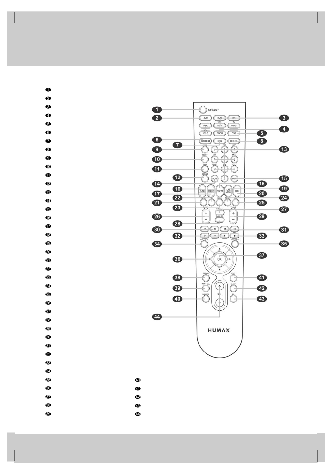
6 MAIN REMOTE CONTROL FUNCTIONS
**
STANDBY Button
AVR Selector
Input Selector
6/8-Channel Input Select
DSP Surround Mode Selector
Stereo Mode Selector
DTS Surround Mode Selector
Dolby Surround Mode Select Button
Program Button
Night Mode Button
OSD Button
Clear Button
Numeric Keys
Mute Button
Memory Button
Tuning Up/Down Button
Preset Up/Down Button
AM/FM Button
Tuning Mode
RDS Button
Speaker Select Button
Channel Select Button
Delay Select Button
Tone Control Button
Test Button
TV Volume Up/Down Button
TV Input Selector
TV Mute
TV Channel Up/Down Selector
Track Skip Buttons
Transport Fast Play/Scan Buttons
Main Transport Controls
REC Button
DVD System Menu Button
DVD Disc Menu Button
Navigation Button
OK Button
Setup Button
Audio Input Select Button
**
Dimmer Button
EXIT Button
Sleep Button
Macro Button
Volume Up/Down Button
**
**
**
**
**
**
**
MAIN REMOTE CONTROL FUNCTIONS 9
**
**
Page 10

**
**
**
**
**
**
**
6 MAIN REMOTE CONTROL FUNCTIONS
**
IMPORTANT NOTE: The AVE-750’s remote may be programmed
to control up to seven devices, including the AVE-750. Before using
the remote, it is important to remember to press the Input Selector
Button
addition, the AVE-750’s remote is shipped from the factory to
operate the AVE-750 and most HUMAX DVD players and
recorders. The remote is also capable of operating a wide variety of
other products using the control codes that are part of the remote.
Before using the remote with other products, follow the instructions
on page 32 to program the proper codes for the products in your
system.
It is also important to remember that many of the buttons on the
remote take on different functions, depending on the product
selected using the Device Control Selectors. The descriptions
shown here primarily detail the functions of the remote when it is
used to operate the AVE-750.
press this button to turn on the AVE-750; press it again to turn the
unit off.
NOTE: The Main Power Switch
button will operate.
that it will operate the AVE-750's functions. If the AVE-750 is in the
standby mode, it will also turn the AVE-750 on.
three actions at the same time. First, if the AVE-750 is not turned
on, this will power up the unit. Next, it will select the source shown
on the button as the input to the AVE-750. Finally, it will change the
remote control so that it controls the device selected. After pressing
one of these buttons you must press the AVR Selector Button
again or wait for seven seconds to operate the AVE-750’s functions
with the remote.
the device connected to the 6-Channel Direct Inputs
8-Channel Direct Inputs
among the available DSP surround modes.
listening mode. The first press of the button places the AVE-750 in
a true, two-channel, left/right Stereo mode with no surround
processing. The next press selects either five-channel Stereo or
seven-channel Stereo, depending on the speaker configuration.
among the available DTS surround modes.
from the available Dolby Surround modes. Each press of this button
will select one of the Dolby Pro Logic II modes or Dolby 3 Stereo.
When a Dolby Digital-encoded source is in use, the Dolby Digital
mode may also be selected.
being controlled, but when programmed for use with a VCR, TV,
cable box, satellite receiver or other similar product it can be used.
mode is available in specially encoded Dolby Digital sources, and it
preserves dialogue (center channel) intelligibility at low volume
levels.
that corresponds to the unit you wish to operate. In
STANDBY Button: When the Main Power Switch is “ON,”
must be turned on before this
AVR Selector: Pressing this button will switch the remote so
Input Selectors: Pressing one of these buttons will perform
6-Channel/8-Channel Input Select: Press this button to select
or the
.
DSP Surround Mode Selector: Press this button to select from
Stereo Mode Selector: Press this button to select a stereo
DTS Surround Mode Selector Press this button to select from
Dolby Surround Mode Selector: This button is used to select
Program Button: This button has no function when the AVE is
Night Mode: Press this button to activate the Night mode. This
OSD Button: Press this button to activate the On-Screen
Display (OSD) system used to set up or adjust the AVE-750’s
parameters.
Clear Button: This button has no function when the AVE is
being controlled, but when programmed for use with a VCR, TV,
cable box, satellite receiver or other similar product it can be used.
Numeric Keys: These buttons serve as a ten-button numeric
keypad to enter tuner preset positions. They are also used to select
channel numbers when TV, Cable or SAT has been selected on the
remote, or to select track numbers on a CD, DVD or LD player,
depending on how the remote has been programmed.
Mute: Press this button to momentarily silence the AVE-750.
Memory Button: Press this button to enter a radio station into
the AVE-750’s preset memory. Once MEMORY flashes in the
Display Line
location using the Numeric Keys
Tuning Up/Down: When the tuner is in use, this button will tune
up or down through the selected frequency band. If the Tuning
Mode Button
appears in the Main Information Display
button will cause the tuner to seek the next station with acceptable
signal strength for quality reception. When AUTO indicator
disappears in the Main Information Display
button will tune stations in single-step increments.
Preset Up/Down Button: When the tuner is in use, press this
button to scroll through the stations programmed into the AVE-750’s
memory.
AM/FM Tuner Select: Press this button to select the AVE-750’s
tuner as the listening choice. Pressing this button when the tuner is
already in use will select between the AM and FM bands.
Tuning Mode: Press this button when the tuner is in use to
select between automatic tuning and manual tuning. When the
button is pressed so that AUTO indicator disappears in the Main
Information Display
move the frequency up or down in single-step increments. When
the FM band is in use, pressing this button for manual tuning when
a station’s signal is weak will change to monaural reception.
RDS Button: Press this button to select RDS mode. RDS
(works only on the FM band) is a broadcasting service which allows
station to send additional information along with the regular
program signal.
Speaker Select: Press this button to begin the process of
configuring the AVE-750’s bass management system. Then press
the
/ Navigation Button to select the channel you wish to
set up. Press the OK Button
configure. When all adjustments have been completed, press the
OK Button
operation.
Channel Select Button: This button is used to start the process
of setting the AVE-750’s output levels to an external source. Once
this button is pressed, press the
select the channel being adjusted, then press the OK Button
followed by the
level setting.
**
**
, you have five seconds to enter a preset memory
.
has been pressed so that AUTO indicator
, pressing either
, pressing this
**
, pressing the Tuning Selector will
and then select another channel to
twice to exit the settings and return to normal
/ Navigation Button to
,
/ Navigation Button again, to change the
**
**
MAIN REMOTE CONTROL FUNCTIONS 10
**
**
**
**
Page 11

**
**
**
**
**
**
**
6 MAIN REMOTE CONTROL FUNCTIONS
**
Delay Select: Press this button to begin the process for setting
the delay times used by the AVE-750 when processing surround
sound. After pressing this button, the delay times are entered by
pressing the OK Button
to change the setting. Press the OK Button again to
complete the process.
Tone Control Button: This button controls whether or not the
Bass and Treble controls are active, and, if so, the degree to which
they are used. The first press of this button tells the current status
of the tone controls: If TONE OUT is displayed in the Display Line
, the tone controls are not in the signal path, and the AVE’s
output is “flat.” If TONE IN is displayed, the controls are active. To
switch the tone controls in or out, press the
Button
actual bass or treble settings, first make certain that TONE IN has
been activated, and then press the button again so that either
BASS MODE or TREBLE MODE appears. Within five seconds,
press the
calibrate the AVE-750’s output levels.
when the AVE is being controlled, but when programmed for use
with a VCR, TV, cable box, satellite receiver or other similar product
it will raise or lower the volume.
controlled, but when programmed for use with a VCR, TV, cable
box, satellite receiver or other similar product it will switch from TV
to other device and vice versa.
controlled, but when programmed for use with a VCR, TV, cable
box, satellite receiver or other similar product it will silence the
device
when the AVE is being controlled, but when programmed for use
with a VCR, TV, cable box, satellite receiver or other similar product
it will change the channel up or down.
function with the AVE-750, but when used with a compatibly
programmed CD or DVD changer it will change the track or chapter
currently being played.
direct function on the AVE-750, but they are used when the remote
is programmed for a compatible DVD, CD or tape player. Pressing
these buttons will transmit a fast-play forward, fast-play reverse, or
fast-forward or -reverse scan command, according to the
capabilities of the player being controlled.
function on the AVE-750, but they are used when the remote is
programmed for a compatible DVD, CD or tape player. Pressing
these buttons will transmit a stop or pause command, according to
the capabilities of the player being controlled.
AVE-750, but it is used when the remote is programmed for a
compatible DVD, CD or tape player. Pressing this button will
transmit a record command, according to the capabilities of the
player being controlled.
so that the desired setting appears. To change the
/ Navigation Button to enter the desired setting.
Test Button: Press this button to begin the sequence used to
TV Volume Up/Down Buttons: This Button has no function
TV Input: This button has no function when the AVE is being
TV Mute: This button has no function when the AVE is being
TV Channel Up/Down Selector: This button has no function
Track Skip Buttons: This button does not have a direct
Transport Fast-Play/Scan Buttons: These buttons have no
Main Transport Controls: These buttons have no direct
REC Button: This button has no direct function on the
and then the / Navigation Button
/ Navigation
DVD System Menu Button: This button has no direct function
on the AVE-750, but it is used when the remote is programmed for
a compatible DVD player. Pressing this button will display a DVD
System Menu on the screen.
DVD Disc Menu Button: This button has no direct function on
the AVE-750, but it is used when the remote is programmed for a
compatible DVD player. Pressing this button will display a DVD Disc
Menu on the screen.
Navigation Button: The button is used to navigate through the
on-screen configuration menus, to scroll through the option list and
to select. To use the button, simply press it left, right, up or down in
the direction indicated by the
Depending on the menu being used, pressing the button will either
change the video highlight that indicates a specific choice or it will
change the option shown in the on-screen or front panel display.
The sections in this manual describing the unit’s individual features
and configuration options contain specific information on how the
navigation controls are used.
OK Button: This button is used to enter settings into the
AVE-750’s memory. It is also used in the setup procedures for
delay time, speaker configuration and channel output level
adjustment.
Setup Button: This button has no direct function on the
AVE-750, but it is used when the remote is programmed for a
compatible DVD, CD or tape player. Pressing this button will begin
a setup process.
Audio Input Select Button: Press this button to assign one of
the digital inputs to a source. (OPTICAL 1 -> OPTICAL 2 ->
OPTICAL 3 -> COAXIAL 1 -> COAXIAL 2 -> COAXIAL 3 ->
ANALOG)
Dimmer Button: This button is used to change the brightness
level of the Main Information Display
the display to one-half brightness, the next press will turn it off.
EXIT Button: This button has no direct function on the
AVE-750, but it is used when the remote is programmed for a
compatible DVD player. Pressing this button will exit from a menu.
Sleep Button: Press this button to place the unit in the Sleep
mode. After the time shown in the display, the AVE-750 will
automatically go into the Standby mode. Each press of the button
changes the time until turn-off in the following order:
**
Macro Button: This button has no direct function on the
AVE-750, but it can be used when the remote is programmed for
other devices.
Volume Up/Down Buttons: To raise the volume, press the
icon on the button and to lower the volume, press the icon.
**
**
icons printed on the button.
**
. The first press will dim
**
**
**
**
MAIN REMOTE CONTROL FUNCTIONS 11
**
**
Page 12

**
**
**
**
**
**
**
7 INSTALLATION AND CONNECTIONS
**
System Installation
**
After unpacking the unit, and placing it on a solid surface capable of
supporting its weight, you will need to make the connections to your
audio and video equipment.
IMPORTANT NOTE: For your personal safety and to avoid possible
damage to your equipment and speakers, it is always a good
practice to turn off and unplug the AVE-750 and ALL source
equipment from the AC output before making any audio or video
system connections.
**
Audio Equipment Connections
We recommend that you use high-quality interconnect cables when
making connections to source equipment and recorders to preserve
the integrity of the signals.
**
Connect the analog output of a CD player to the CD Inputs .
1.
NOTE: If your CD player has both fixed and variable audio outputs,
it is best to use the fixed output unless you find that the input to the
receiver is so low that the sound is noisy, or so high that the signal
is distorted.
**
Connect the analog Play/Out jacks of a cassette deck, MD,
2.
CD-R or other audio recorder to the Tape Inputs
the analog Record/In jacks on the recorder to the Tape
Outputs
Connect the output of any digital sources such as a CD or DVD
3.
changer or player, video game, a digital satellite receiver, HDTV
tuner or digital cable set-top box or the output of a compatible
computer sound card to the Optical or Coaxial Digital Inputs
Connect the coaxial or optical Digital Audio Outputs on the
4.
rear panel of the AVE-750 to the matching digital input
connections on a CD-R or MiniDisc recorder.
Assemble the AM Loop Antenna supplied with the unit so that
5.
the tabs at the bottom of the antenna loop snap into the holes in
the base. Connect the wires from the AM antenna to the
Antenna Terminals
marked GND to the top terminal screw.
**
**
Connect the supplied FM antenna to the FM Antenna (75-ohm)
6.
Connection
antenna, an inside powered or wire-lead antenna or a
connection from a cable TV system. If the antenna or
connection uses 300-ohm twin-lead cable, you must use an
optional 300-ohm-to-75-ohm adapter.
Connect the front, center, surround and surround back
7.
speakers outputs
on the AVE-750.
.
. Make certain to connect the wire
. The FM antenna may be an external roof
to the respective speakers.
. Connect
To ensure that all the audio signals are carried to your speakers
without loss of clarity or resolution, we suggest that you use
high-quality speaker cable. Many brands of cable are available and
the choice of cable may be influenced by the distance between your
speakers and the receiver, the type of speakers you use, personal
preferences and other factors. Your dealer or installer is a valuable
resource to consult in selecting the proper cable.
Regardless of the brand of cable selected, we recommend that you
use a cable constructed of fine, multistrand copper with an area
greater than 2
Cable with an area of 1.5 may be used for short runs of less
than 4 m. We do not recommend that you use cables with an area
less than 1
performance that will occur.
Cables that are run inside walls should have the appropriate
markings to indicate listing with any appropriate testing agency
standards. Questions about running cables inside walls should be
referred to your installer or a licensed electrician who is familiar with
the applicable local building codes in your area.
When connecting wires to the speakers, be certain to observe
proper polarity. Note that the positive (+) terminal of each speaker
connection now carries a specific color code as noted on page 7.
However, most speakers will still use a red terminal for the postive
(+) connection. Connect the “negative” or “black” wire to the same
terminal on both the receiver and the speaker.
NOTE: While most speaker manufacturers adhere to an industry
convention of using black terminals for negative and red ones for
positive, some manufacturers may vary from this configuration. To
ensure proper phase and optimal performance, consult the
identification plate on your speaker or the speaker’s manual to
verify polarity. If you do not know the polarity of your speaker, ask
your dealer for advice before proceeding, or consult the speaker’s
manufacturer.
We also recommend that the length of cable used to connect
speaker pairs be identical. For example, use the same length of
cable to connect the front left and front right, surround left and
surround right, and surround back left and surround back right
speakers, even if the speakers are at different distances from the
AVE-750.
**
Connections to a subwoofer are normally made via a line-level
8.
audio connection from the LFE/Subwoofer Output
LFE or line-level input of a subwoofer with a built-in amplifier.
When a passive subwoofer is used, the connection first goes to
a power amplifier, which will be connected to one or more
subwoofer speakers. If you are using a powered subwoofer that
does not have line-level input connections, follow the
instructions furnished with the speaker for connection
information.
If an external multichannel audio source with 5.1 outputs such
9.
as an external digital processor/ decoder, DVD-Audio or SACD
player is used, connect the outputs of that device to the
6-Channel Direct Inputs
If an external multichannel audio source with 7.1 outputs such
10.
as an external digital processor/ decoder, DVD-Audio or SACD
player is used, first connect the outputs of that device to the
6-Channel Direct Inputs
Back Left and Surround Back Right output channels of the
source device to the 8-Channel Direct Inputs
**
**
.
due to the power loss and degradation in
**
to the
.
, and then connect the Surround
.
**
**
INSTALLATION AND CONNECTIONS 12
**
**
**
**
Page 13

**
**
**
**
**
**
**
7 INSTALLATION AND CONNECTIONS
**
If you have a camcorder, video game or other audio/video
Video Equipment Connections
Video equipment is connected in the same manner as audio
components. Again, the use of high-quality interconnect cables is
recommended to preserve signal quality.
Note that the AVE-750 will not convert signals from composite to
S-Video, or vice versa. S-Video inputs may only be viewed when
the AVE-750 is connected to a TV set or video display with S-Video
capability. If you use both standard composite video and S-Video
sources in your system, it is important that you connect both an
S-Video cable and a standard composite video cable (a coax cable
with an RCA plug on both ends) between the AVE-750 and your TV
or projector. Consult the instructions for your TV set or projector for
more information on connecting both types of signals.
**
Connect a VCR’s or other video source’s audio and video
1.
Play/Out jacks to the Video 1 In Jacks
The Audio and Video Record/In jacks on the VCR should be
connected to the Video 1 Out Jacks
Connect the analog audio and video outputs of a television set
2.
or any other video source to the Video 2 Input Jacks
Connect the analog audio and video outputs of a DVD or laser
3.
disc player to the DVD Jacks
connection is used for your DVD player, the default connection
is the Coaxial 1 Digital Audio Input Jack
connection may also be made to any of the Optical
Coaxial
source selection is changed as shown on pages 16 and 26. If
your DVD or DVD-Audio player includes an onboard surround
decoder and 6- or 8-channel line-level audio outputs, you may
connect these audio outputs to the 6- and 8-Channel Direct
Inputs as appropriate. When you wish to hear this decoded
audio, select the DVD input first in order to select the video
signal from the DVD player, then select the 6- and 8-Channel
Direct Inputs
Connect the digital audio outputs of a DVD player, satellite
4.
receiver, cable box or HDTV converter to the appropriate
Optical or Coaxial Digital Inputs
Connect the Video Monitor Output Jacks on the receiver to
5.
the composite or S-Video input of your television monitor or
video projector.
If your DVD player and monitor both have component video
6.
connections, connect the component outputs of the DVD player
to the DVD Component Video Inputs
component video connections are used, the audio connections
should still be made to either the analog DVD Audio Inputs
or any of the Optical or Coaxial Digital Input Jacks
.
If another component video device is available, connect it to the
7.
Video 2 Component Video Input Jacks
connections for this device should be made to either the Video
2 Audio Input Jacks
Digital Input Jacks
If the component video inputs are used, connect the Video
8.
Monitor Component Video Outputs
video inputs of your TV, projector or display device.
digital audio inputs, provided that the digital input
source for the audio.
or any of the Optical or Coaxial
. When a digital audio
.
on the rear panel.
on the AVE-750.
.
. However, the
or
.
. Even when
. The audio
to the component
9.
device that is connected to the receiver on a temporary rather
than permanent basis, connect the audio, video and digital
audio outputs of that device to the Video 3 Input/Output Jacks
. A device connected here is selected as the Video 3 input,
and the digital inputs must be assigned to the Video 3 input.
(See pages 16 and 26 for more information on input
configuration.)
**
VIDEO CONNECTION NOTES:
When the component video jacks are used, the onscreen
•
menus are not visible and you must switch to the standard
composite or S-Video input on your TV to view them.
The AVE-750 will accept either standard composite, S-Video or
•
Y/Pb/Pr component video signals. However, it will not convert
composite or S signals to component video.
Component or composite video signals may only be viewed in
•
their native formats.
**
System and Power Connections
**
The AVE-750 is designed for flexible use with external control
components and power amplifiers.
**
AC Power Connections
This unit is equipped with an AC Accessory Outlet . It may be
used to power accessory devices, but it should not be used with
high-current draw equipment such as power amplifiers. The total
power draw for the outlet may not exceed 50 watts.
The outlet is switched, which means that power is supplied only
when the AVE is turned on. Since the power is removed when the
AVE is turned off, this outlet should not be used for devices such as
VCR's where a constant power source is required for a clock or
timer, or for products that do not have a mechanical power switch
and thus turn off when AC power is removed.
You’re almost ready to enjoy the AVE-750!
**
**
**
**
**
**
**
INSTALLATION AND CONNECTIONS 13
**
**
Page 14
**
**
**
**
**
**
8 SYSTEM CONFIGURATION
**
When all audio, video and system connections have been made,
there are a few configuration adjustments that must be made. A
few minutes spent to correctly configure and calibrate the unit will
greatly add to your listening experience.
**
Speaker Selection and Placement
The placement of speakers in a multichannel home theater
system can have a noticeable impact on the quality of sound
reproduced.
No matter which type or brand of speakers is used, the same
model or brand of speaker should be used for the left front, center
and right front speakers. This creates a seamless front
soundstage and eliminates the possibility of distracting sonic
disturbances that occur when a sound moves across mismatched
front channel speakers.
**
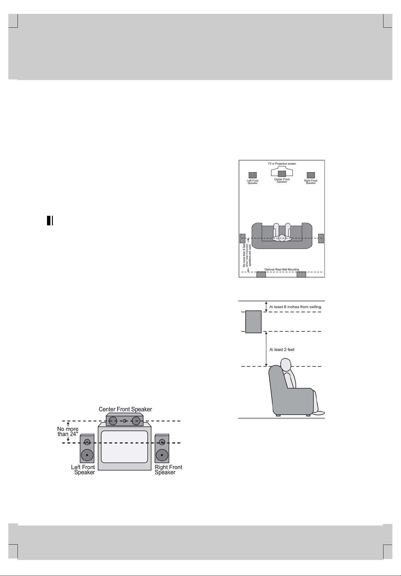
Speaker Placement
**
Depending on the type of center channel speaker in use and your
viewing device, place the center speaker either directly above or
below your TV, or in the center behind a perforated front
projection screen.
Once the center channel speaker is installed, position the front left
and front right speakers so that they are as far away from one
another as the center channel speaker is from the preferred
listening position. Ideally, the front channel speakers should be
placed so that their tweeters are no more than 24" above or below
the tweeter in the center channel speaker.
Depending on the specifics of your room acoustics and the type of
speakers in use, you may find that imaging is improved by moving
the left front and right front speakers slightly forward of the center
channel speaker. If possible, adjust all front loudspeakers so that
they are aimed at ear height when you are seated in the listening
position.
Using these guidelines, you’ll find that it takes some
experimentation to find the correct location for the front speakers
in your particular installation. Don’t be afraid to move things
around until the system sounds correct. Optimize your speakers
so that audio transitions across the front of the room sound
smooth, and that sounds from all speakers appear to arrive at the
listening position at the same time (without delay from the center
speaker compared to the left and right speakers).
**
**
When the AVE-750 is used in 5.1-channel operation, the preferred
location for surround speakers is on the side walls of the room, at
or slightly behind the listening position. In a 7.1-channel system,
both side surround and back surround speakers are required. The
center of the speaker should face into the room. The speakers
should be located so that the bottom of the cabinet is at least two
feet higher than the listeners’ ears when the listeners are seated
in the desired area.
**
B) Rear speaker mounting is an alternate location for 5.1 systems. It is
required for 7.1 operation.
**
**
**
**
**
**
A) Front channel speaker installation with direct-view TV sets or rear-screen
projectors.
SYSTEM CONFIGURATION 14
**
Rear surround speakers are required when a full 7.1- channel
system is installed, and they may also be used as an alternative
mounting position in a 5.1-channel system when it is not practical
to place the main surround speakers on the sides of the room.
Speakers may be placed on a rear wall, behind the listening
position. As with the side speakers, rear surrounds should be
located so that the bottom of the cabinet is at least two feet higher
than the listeners’ ears. The speakers should be no more than six
feet behind the rear of the seating area.
**
**
**
**
Page 15

**
**
**
**
**
**
8 SYSTEM CONFIGURATION
**
Subwoofers produce nondirectional sound, so they may be placed
almost anywhere in a room. Actual placement should be based on
room size and shape and the type of subwoofer used. One
method of finding the optimal location for a subwoofer is to begin
by placing it in the front of the room, about six inches from a wall,
or near the front corner of the room. Another method is to
temporarily place the subwoofer at your normal listening position,
and then walk around the room until you find a spot where the
subwoofer sounds best. Place the subwoofer in that spot. You
should also follow the instructions of the subwoofer’s
manufacturer, or you may wish to experiment with the best
location for a subwoofer in your listening room.
**
System Setup
Once the speakers have been placed in the room and connected,
the remaining steps in the setup process are to program the
AVE-750’s bass management system for the type of speakers
used in your system, calibrate the output levels, and set the delay
times used by the surround sound processor.
You are now ready to power up the AVE-750 to begin these final
adjustments.
Plug the AC Power Cord into an unswitched AC outlet.
1.
Open the door on the lower right corner of the front panel to
2.
reveal the Main Power Switch
jacks by gently pulling the door down from the side of the unit.
Press the Main Power Switch
Remove the protective plastic film from the front panel lens. If
3.
left in place, the film may affect the performance of your
remote control.
Install the two supplied AA batteries in the remote as shown.
4.
Be certain to follow the (+) and (–) polarity indicators that are
printed inside the battery compartment. Use the alkaline
batteries for longer use of the remote.
**
and the other front panel
in until it latches.
**
To view the on-screen menus, make certain you have made a
connection from the Video Monitor Outputs
to the composite or S-Video input of your TV or projector. In order
to view the AVE-750’s displays, the correct video source must be
selected on the video display. Note that the on-screen menus are
not available when a component video display is in use.
IMPORTANT NOTE: When viewing the on-screen menus using a
CRT-based projector, plasma display or any direct-view CRT
monitor or television, it is important that they not be left on the
screen for an extended period of time. The constant display of a
static image such as these menus or video game images may
cause the image to be permanently “burned into” the projection
tubes, plasma screen or CRT. This type of damage is not covered
by the AVE-750 warranty and may not be covered by the
projector/TV set’s warranty.
The AVE-750 has two on-screen display modes, “Semi-OSD” and
“Full-OSD.” When making configuration adjustments, it is
recommended that the Full-OSD mode be used. This will place an
option listing on the screen, making it easier to view the available
options.
**
Making Configuration Adjustments
The full-OSD system is available by pressing the OSD Button
. When this button is pressed, the MAIN MENU (Figure 1) will
appear, and adjustments are made from the individual menus.
**
on the rear panel
**
**
**
**
Turn the AVE-750 on either by pressing the STANDBY
5.
Button
STANDBY Button
Input Selectors
Display
**
on the front panel, or via the remote by pressing the
, the AVR Selector or any of the
on the remote. The Main Information
will light.
Using the On-Screen Display
When making the following adjustments, you may find it easier to
use the AVE-750’s on-screen display system. These easy-to-read
displays give you a clear picture of the current status of the unit
and make it easy to see which speaker, delay, input or digital
selection you are making.
Figure 1
The semi-OSD system is also available, allowing you to make
adjustments directly, by pressing the appropriate buttons on the
front panel or remote control for the specific parameter to be
adjusted. For example, to change the digital input for any of the
sources, press the Audio Input Select Button
or use the front panel buttons following the instructions shown on
page 17. To use the full-OSD menu system, press the OSD
Button
Navigation Buttons until the item you wish to adjust is
highlighted in a white box and then press the OK Button
adjust that item. The menus will remain on the screen for 20
seconds, and then they will “time-out” and disappear from the
screen. The time-out may be increased to as much as 50 seconds
by going to the ADVANCED menu, and changing the item titled
FULL OSD TIME OUT.
When the full-OSD system is in use, the menu selections are not
shown in the Main Information Display
menu system is used, OSD ON will appear in the Display Line
. When the semi-OSD system is used in conjunction with the
discrete configuration buttons, the on-screen display will show the
current menu selection. That selection will also be shown in the
Display Line
. When the menu is on the screen, press the /
.
on the remote,
to
. When the full-OSD
**
**
**
**
SYSTEM CONFIGURATION 15
**
**
Page 16

**
**
**
**
**
**
8 SYSTEM CONFIGURATION
**
Speaker Optimizer
The Speaker Optimization function is critical to ensure optimal
performance of the AVE. This setting tells the digital amplifier
section which settings to use to best match its operation to your
specific speakers. Note that this adjustment is electronic, not
electrical, and unlike the “8-ohm/4-ohm” switches on older analog
amplifiers, you do not need to turn the AVE off to change the
setting. However, we do suggest that you do not have any
program material playing through the AVE when the setting is
changed.
Before making this adjustment you will need to find the impedance
specification for your speakers. This information is often found on
a label attached to the speaker, and it is usually shown in the
owner’s manual that came with your speakers. If you cannot find
the information for your speakers, consult the manufacturer’s Web
site or customer service department.
In cases where the speakers in a system have different
impedance ratings, such as 8 ohms for the front left/right and
center speakers and 6 ohms for the surround speakers, use the
setting for the front speakers, as they are used most often for all
types of program material.
If you cannot determine the speaker’s impedance, there is no
harm in using the factory default setting of 8 ohms, as most home
speakers are in that range.
Since the factory default is 8 ohms, you may skip this section if
that is the setting appropriate to your system. If you do want to
change the setting, follow these steps.
Press the OSD Button
appears on your display. Press the
that SPKR OPTIMIZER is highlighted and then press the
Navigation Buttons until the desired setting appears.
When the correct impedance figure is on the screen, press the
Navigation Button so that IN/OUT SETUP is highlighted and
proceed to the following section to configure the remaining
settings for your AVE.
**
Setting the System Configuration Memory
The AVE-750 features an advanced memory system that enables
you to establish different configurations for the speaker
configuration, digital input, surround mode, delay times, crossover
frequency and output levels for each input source. This flexibility
enables you to customtailor the way in which you listen to each
source and have the AVE-750 memorize those settings. This
means, for example, that you may use different output levels or
trims for different sources, or set different speaker configurations
with the resultant changes to the bass management system. Once
these settings are made, they will automatically be recalled
whenever you select that input.
The factory default settings for the AVE-750 have all inputs except
for DVD configured for an analog audio input except for the DVD
input, where the Coaxial 1 Digital Audio Input
The default speaker settings are “SMALL” for all speaker
positions, and for the subwoofer to be on. The default setting for
the surround modes is 5CH stereo, although Dolby Digital or DTS
will automatically be selected as appropriate when a source with
digital encoding is in use.
so that the MAIN MENU (Figure 1)
Navigation Button so
/
is the default.
**
Before using the unit, you will probably want to change the
settings for most inputs so that they are properly configured to
reflect the use of digital or analog inputs, the type of speakers
installed and the surround mode specifics of your home theater
system. Remember that since the AVE-750 memorizes the
settings for each input individually, you will need to make these
adjustments for each input used. However, once they are made,
further adjustment is only required when system components are
changed.
To make this process as quick and as easy as possible, we
suggest that you use the full-OSD system with the on-screen
menus, and step through each input. Once you have completed
the settings for the first input, many settings may be duplicated for
the remaining inputs. It is also a good idea to set the configuration
data in the order these items are listed in the MAIN MENU as
some settings require a specific entry in a prior menu item.
Remember that once the settings are made for one input, they
must be made for all other input sources in your system.
**
Input Setup
**
The first step in configuring the AVE-750 is to configure each
input. When using the full-OSD system to make the setup
adjustments, press the OSD Button
MENU (Figure 1) appears. The IN/OUT SETUP line will be
highlighted. Press the OK Button
IN/OUT SETUP menu (Figure 2) will appear on the screen. Press
the
/ Navigation Buttons until the desired input name
appears. If the input will use the standard left/right analog inputs,
no further adjustment is needed.
**
Figure 2
If you wish to associate one of the digital inputs with the selected
input source, press the
IN/OUT SETUP menu (Figure 2) is on the screen, and the
DIGITAL IN line will be highlighted in reverse text. Press the
Navigation Buttons until the name of the desired digital
input appears. To return to the analog input, press the buttons
until the word ANALOG appears. When the correct input source
appears, press the
RETURN TO MAIN MENU is highlighted, and press the OK
Button
To change the digital input at any time using the remote control
and the semi-OSD system, press the Audio Input Select Button
Button
Display Line
AVE-750. Press the OK Button
assignment.
.
. Make your input selection using the Audio Input Select
until the desired digital or analog input is shown in the
and in the video display connected to the
Navigation Button while the
Navigation Button once so that
once so that the MAIN
to enter the menu and the
to enter the new digital input
**
**
**
/
**
**
SYSTEM CONFIGURATION 16
**
**
**
**
Page 17

**
**
**
**
**
**
8 SYSTEM CONFIGURATION
**
To change the digital input from the front panel, press the Set
Button
MODE appears in the Display Line
the Set Button
again to cycle through the list of available inputs. When the
desired digital input (or the analog input) name appears in the
Display Line
enter your choice into the unit’s memory. The AVE-750 will return
to normal operation and displays within five seconds.
NOTE: When a source such as an HDTV receiver or a digital
cable set-top box is used, you may wish to connect both the
coaxial digital output and the standard, analog output of the
source to the AVE’s VID 2 input since the program sources and
channels received by these devices often switch between analog
and digital audio.
An exclusive HUMAX feature is the ability to switch the front panel
coaxial digital audio and analog audio/video jacks from their
normal use as inputs to output connections so that portable
recording devices may easily be connected. On the AVE-750, the
Digital Coax 3 Jack
switched to a digital output for use with CD-R/RW decks, MD
recorders or other A/V recorders. To change the jack to an output,
press the
SETUP menu is on the screen until COAXIAL 3 is highlighted.
Then press the
OUT appears. The Input/Output Status Indicator
indicating that the jack is now a record output.
NOTE: A signal will be sent to this jack only when the input
selected for use by the AVE-750 is digital. Digital signals will be
passed through regardless of their format, and which digital input
(optical or coax) they are fed from. However, analog signals are
not converted to digital, and the signal’s format (e.g., PCM, Dolby
Digital or DTS) may not be changed.
Selection of the front panel jacks as an output will remain effective
as long as the AVE-750 is on. Once the unit is turned off, the jacks
will revert to their normal use as an input when the unit is turned
on again.
The front panel analog Video 3 Input/Output Jacks
normally set as an input for use with camcorders, video games
and other portable audio/video products, but they may be
switched to an output for connection to portable audio/video
recorders. To temporarily switch them to outputs, you must first be
at the IN/OUT SETUP menu. Press the
until the VIDEO 3 line is highlighted. Press the Navigation
Button
Input/Output Status Indicator
video jacks will turn red, indicating that the analog Video 3 jacks
are now record outputs.
**
Surround Setup
Once the basic input setup has been completed, the next step is
to select the surround mode you wish to use with an input. Since
surround modes are a matter of personal taste, feel free to select
any mode you wish – you may change it later. However, to make it
easier to establish the initial parameters for the AVE-750, it is best
to select Dolby Pro Logic II for most analog inputs and Dolby
Digital for inputs connected to digital sources. In the case of inputs
such as a CD Player, Tape Deck or Tuner, you may wish to set
the mode to Stereo (“Surround Off”) as they are not typically used
with surround-encoded material.
and then press the / Buttons until DIG SEL
. Within five seconds, press
again, and then press the / Buttons
and in the on-screen display, Set Button to
is normally an input, but it may be
/ Navigation Buttons while the IN/OUT
/ Navigation Buttons so that the word
will turn red,
are
Navigation Button
so that the word OUT appears. Note that the
between the S- and composite
**
It is easiest to complete the surround setup using the full-OSD
on-screen menus. From the MAIN MENU (Figure 1), press the
Navigation Buttons until SURROUND SELECT is
highlighted. Press the OK Button
SELECT menu (Figure 3) is on the screen.
**
Figure 3
Each of the lines on the menu (Figure 3) contains a category
menu surround mode and within those menus you may choose
one of the sub-modes. The list of submodes in some categories
will vary according to whether 5.1 or 6.1/7.1 operation is chosen.
Also, some of the modes available in the AVE-750 will not appear
unless a digital source is selected and playing the correct
bitstream.
The selection of 5.1 or 6.1/7.1 configuration is determined by the
setting for Surround Back Speakers in the Speaker Setup menu.
The factory setting is for “None,” which will mean that only 5.1
modes will be available. To utilize the 6.1/7.1 surround modes,
change the setting for the Surround Back Speakers to either Large
or Small, as shown in the instructions on page 19. This will
automatically activate all 6.1/7.1 surround mode options.
To select the mode that will be used as the initial default for an
input, first press the
on-screen cursor is next to the desired mode’s master category
name. Next, press the OK Button
Press the
available choices, and then press the
so that the cursor is next to RETURN TO MAIN MENU to continue
the setup process.
On the DOLBY SURR menu (Figure 4), the choices include Dolby
Digital, Dolby Pro Logic II Music, Dolby Pro Logic II Movie, Dolby
Pro Logic and Dolby 3 Stereo. When a 6.1/7.1 speaker
configuration is used, Dolby Digital EX replaces the Dolby Digital
mode. For a complete explanation of these modes, see page 25.
Note that when a Dolby Digital mode is selected there are
additional settings available for the Night mode.
Note also that some of the available surround mode combinations
include both Dolby Digital and the various options for Dolby Pro
Logic II. These are used with DVD or other Dolby Digital sources
such as digital cable or some high-definition television programs
where Dolby Digital is used to carry the soundtrack, but the
soundtrack itself is only two-channel stereo. Check the Dolby
Digital icon information on the back of a DVD or the program
listings for your cable, satellite or HDTV station to see whether the
programming is Dolby Digital 5.1 or 2.0. When the AVE-750
detects a Dolby Digital 2.0 signal, it will automatically default to the
Dolby Pro Logic surround mode.
/ Navigation Buttons to scroll through the
/ Navigation Buttons until the
so that the SURROUND
to view the sub-menu.
Navigation Button
**
**
/
**
**
**
**
**
SYSTEM CONFIGURATION 17
**
**
Page 18

**
**
**
**
**
**
8 SYSTEM CONFIGURATION
**
Figure 4
The Night mode is a feature of Dolby Digital that uses special
processing to preserve the dynamic range and full intelligibility of a
movie sound track while reducing the peak level. This prevents
abruptly loud transitions from disturbing others, without reducing
the sonic impact of a digital source. The Night mode is only
available when specially encoded Dolby Digital signals are played.
To adjust the Night mode setting for an input from the menu, make
certain that the NIGHT line of the DOLBY SURR menu (Figure 4)
is highlighted. Next, press the
choose between the following settings, as they appear in the
on-screen display:
OFF: When OFF appears, the Night mode will not function.
MID: When MID appears, a mild compression will be applied.
MAX: When MAX appears, a more severe compression algorithm
will be applied.
We recommend the MID setting as a starting point and the MAX
setting as an alternative. The Night mode may be adjusted directly
any time that a Dolby Digital source is playing by pressing the
Night Mode Button
D-RANGE will appear in the lower third of the video screen and in
the Display Line
within three seconds to select the desired setting.
On the DTS menu, the choices made are determined by a
combination of the type of DTS program material in use and
whether the 5.1 or 6.1/7.1 speaker output configuration is in use.
When either of the speaker configurations is in use, you may
select either the Neo:6 Music or Neo:6 Cinema mode to deliver an
enhanced 5.1- or 6.1-channel sound field.
When a 5.1 speaker configuration is in use, the AVE will
automatically select the 5.1 version of DTS processing when a
DTS data stream is selected. When a 6.1/7.1 speaker
configuration is in use, the DTS-ES Discrete mode will
automatically be activated when a DTS source with the ES
Discrete “flag” is in use. When a non-ES DTS disc is in use, you
may select the DTS-ES Matrix mode through this menu to create
a full eight-speaker surround mode. See page 25 for a complete
explanation of the DTS modes.
On the DSP menu, the choices are the DSP surround modes
designed for use with two-channel stereo programs to create a
variety of sound field presentations. The choices available are Hall
1, Hall 2 ,Theater, Stadium, Classic, Panorama, Movie or Music.
See page 25 for a complete explanation of the DSP surround
modes.
. Press the / Navigation Buttons
/ Navigation Buttons to
. When the button is pressed, the phrase
**
On the STEREO menu, the choices will either turn the surround
processing off for a traditional two-channel stereo presentation, or
select 5 CH STEREO or 7 CH STEREO depending on whether a
5.1 or 6.1/7.1 configuration is in use. The latter modes feed a two
channel presentation to all speakers, regardless of the number of
speakers in use. See page 25 for a complete explanation of the 5
CH STEREO and 7 CH STEREO modes.
After the selections are made on the Dolby, DTS, DSP or Stereo
menus, press the
cursor moves to the RETURN TO SURR SELECT line and press
the OK Button
/ Navigation Buttons to highlight the RETURN TO MAIN
MENU option, and press the OK Button
MENU.
**
Speaker Setup
This menu tells the AVE-750 which type of speakers are in use.
This is important as it adjusts the settings that decide whether
your system will use the “5-channel” or “6-channel/7-channel”
modes, as well as determining which speakers receive
low-frequency (bass) information.
For each of these settings, use the LARGE setting if the speakers
for a particular position are traditional full-range loudspeakers.
Use the SMALL setting for smaller, frequency-limited satellite
speakers that do not reproduce sounds below 200Hz. Note that
when “small” speakers are used, a subwoofer is required to
reproduce low-frequency sounds. Remember that the “large” and
“small” descriptions do not refer to the actual physical size of the
speakers, but to their ability to reproduce low-frequency sounds. If
you are in doubt as to which category describes your speakers,
consult the specifications in the speakers’ owner’s manual, or ask
your dealer.
This menu screen also allows you to enter the settings for the
AVE-750’s Triple Crossover feature that allows a different
crossover point to be used for the front left/right, center and
surround speakers. In systems where full-range or tower speakers
are used for the front soundstage or where different brands or
models are in use at the various speaker positions, this feature
allows you to customize the bass management circuits with a
precision not previously possible. It is easiest to enter the proper
settings for the speaker setup through the SPEAKER SETUP
menu (Figure 5). If that menu is not already on your screen from
the prior adjustments, press the OSD Button
MAIN MENU (Figure 1), and then press the
until the cursor is on the SPEAKER SETUP line. At this point,
press the OK Button
(Figure 5).
**
/ Navigation Buttons so that the
.IntheSURROUND SELECT menu use the
to return to the MAIN
to bring up the
Navigation Button
to bring up the SPEAKER SETUP menu
**
**
**
**
**
SYSTEM CONFIGURATION 18
**
**
Figure 5
**
**
Page 19

**
**
**
**
**
**
8 SYSTEM CONFIGURATION
**
The first line of the SPEAKER SETUP menu (Figure 5) allows you
to switch the menu to change either the underlying speaker size
setting or the exact crossover point used for that speaker group.
For the first pass through the menu, leave the setting at its default
option of SIZE, and then proceed as outlined below. Once the
speaker choices have been set you may wish to return to this line
to change the option so that the crossover settings may be
adjusted.
Begin the speaker setup process by making certain that the
LEFT/RIGHT line is highlighted in reverse video, which sets the
configuration for the front left and right speakers. If you wish to
make a change to the front speakers’ configuration, press the
Navigation Buttons so that either LARGE or SMALL
appears, matching the appropriate description from the definitions
on page 19.
When SMALL is selected, low-frequency sounds will be sent only
to the subwoofer output. If you choose this option and there is no
subwoofer connected, you will not hear any low-frequency sounds
from the front channels.
When LARGE is selected, a full-range output will be sent to the
front left and front right outputs. Depending on the choice made in
the SUBWOOFER line in this menu, bass information may also be
directed to the front left/right speakers, a subwoofer or both.
NOTE: When the front speakers are set to the LARGE option and
the surround mode is set to "Surround Off," or pure two-channel
stereo, when an analog signal source is present it will be routed
directly from the input to the volume control without being digitized
or processed. If you have full-range front speakers and wish to
remove all digital processing from the circuit path, select this
configuration. If you wish to set this option for use with only one
input, such as a CD player that uses an external DAC or an
optional, external phono preamp, you may also wish to choose the
INDIVIDUAL setting on the BASS MGR line at the bottom of this
menu so that only those inputs where the analog bypass is
desired will be routed in this fashion, while other analog inputs
such as a VCR or cable box will be digitized for surround
processing.
When you have completed your selection for the front channel,
press the
to CENTER.
Press the
best describes your system, based on the definitions shown on
page 18.
When SMALL is selected, low-frequency surround channel
sounds will be sent to the subwoofer output only. If you choose
this option and there is no subwoofer connected, you will not hear
any low-frequency sounds from the surround channel.
When LARGE is selected, a full-range output will be sent to the
center speaker output, and no center channel signal will be sent to
the subwoofer output.
When NONE is selected, no signals will be sent to the center
channel output. The receiver will operate in a “phantom” center
channel mode and center channel information will be sent to the
left and right front channel outputs.
When you have completed your selection for the center channel,
press the
to SURROUND. Press the
select the option that best describes the surround speakers in
your system based on the definitions shown on page 18.
Navigation Button to move the highlighted video
/ Navigation Buttons to select the option that
Navigation Button to move the highlighted video
/ Navigation Buttons to
**
**
**
When SMALL is selected, low-frequency surround channel
sounds will be sent to the subwoofer output only. If you choose
this option and there is no subwoofer connected, you will not hear
any low-frequency sounds from the surround channel.
When LARGE is selected, a full-range output will be sent to the
surround channel outputs, and no surround channel signals will be
sent to the subwoofer output.
When NONE is selected, surround sound information will be split
between the front left and front right outputs.
/
When you have completed your selections for the main surround
channels, press the
highlighted video to SURR BACK. This line enters the setting for
the surround back channels when they are present, and it also
tells the AVE-750’s processing system to configure the unit for
either 5.1 or 6.1/7.1 operation.
Press the
best describes the speakers in use at the left and right back
surround positions based on the definitions on page 18.
When NONE is selected, the system will adjust so that only
5.1-channel surround modes are available and the surround back
amplifier channels will not be used.
When SMALL is selected the system will adjust so that the full
complement of 6.1/7.1 surround modes is available, and
low-frequency information below the crossover point will be sent to
the subwoofer output. If you choose this option with no subwoofer
connected, you will not hear low-frequency sounds from the
surround back channel.
When LARGE is selected the system will adjust so that the full
complement of 6.1/7.1 surround modes is available, and a
full-range signal will be sent to the surround back channels, with
no low-frequency information sent to the subwoofer output.
When you have completed your selection for the back surround
channels, press the
move the highlighted video to SUBWOOFER.
Press the
best describes your system. The choices available for the
subwoofer position will depend on the settings for the other
speakers, particularly the front left/right positions .
If the front left/right speakers are set to SMALL, the subwoofer will
automatically be set to SUB.
If the front left/right speakers are set to LARGE, three options are
available:
If no subwoofer is connected, press the / Navigation
•
Buttons
menu. When this option is selected, all bass information will
be routed to the front left/right “main” speakers.
If a subwoofer is connected, you have the option to have the
•
front left/right “main” speakers reproduce bass frequencies at
all times, and have the subwoofer operate only when a digital
source with a dedicated Low-Frequency Effects, or LFE,
soundtrack is in use. This allows you to use both your main
and subwoofer speakers to take advantage of the bass
created for certain movies. Press the
Buttons
menu for this option.
/ Navigation Buttons to select the option that
/ Navigation Buttons to select the option that
Navigation Button to move the
Navigation Button on the remote to
so that SUB NONE appears in the on-screen
/ Navigation
so that SUB (LFE) appears in the on-screen
**
**
**
**
**
SYSTEM CONFIGURATION 19
**
**
Page 20

**
**
**
**
**
**
8 SYSTEM CONFIGURATION
**
To use a subwoofer for bass reproduction in conjunction with
•
the main front left/right speakers, regardless of the type of
program source or Surround mode you are listening to, press
the
/ Navigation Buttons so that L/R+LFE appears.
When this option is selected, a full-range signal will be sent to the
front left/right “main” speakers, and the subwoofer will receive the
bass frequencies under frequency selected, as described below.
When all initial speaker “size” settings have been made, you may
then take advantage of the AVE-750’s Triple Crossover system,
which allows individual crossover settings to be made for each
speaker grouping. The low frequency crossover point is set by the
design of your speakers. Depending on the design and driver
complement of your speakers, it is defined as the frequency which
is either the lowest possible frequency the speaker is capable of
reproducing, or the frequency at which sound is sent to the
speaker’s internal low-frequency driver, as opposed to the
mid-range driver. Before making any changes to the settings for
the crossover point we suggest that you find the crossover point
for the speakers in each of the three groupings, front left/right,
center front and surrounds by looking at the specifications page of
the speaker’s owner’s manual, by getting that information from the
manufacturer’s Web site, or by contacting your dealer or the
manufacturer’s customer service department. You will need this
data to accurately configure the next group of settings.
The factory default setting for all speaker positions is 100Hz. If
that setting is acceptable for all channels, no adjustments are
needed and you may skip this section. To change one of the
settings, press the
moves back up to the top of the list of setting options. Press the
/ Navigation Buttons so that X-OVER is highlighted and
the menu will change to the screen shown in Figure 6.
**
Figure 6
To change the setting for any of the three speaker groups, press
the
/ Navigation Buttons until the cursor is next to the
line where you wish to make a change and then press the
Navigation Buttons until the desired setting appears. The
available choices at which point low-frequency information will be
sent to the subwoofer, rather than to the main speaker channel,
are 40Hz, 60Hz, 80Hz, 100Hz, 120Hz and 200Hz. Pick the choice
that is identical to the information for the speakers, or if an exact
match is not possible, pick the closest choice that is above the
speaker’s low frequency limit or crossover point to avoid the
creation of a low-frequency “hole” where your system will have no
bass information.
Navigation Button so that the cursor
/
**
In cases where LARGE has been selected as the front channel
speaker option and L/R+LFE has been selected as a the
subwoofer option, the front channel sound information below the
setting shown will be sent to both the front channel speakers and
the subwoofer.
The subwoofer’s crossover point will automatically adjust to meet
the setting for each speaker grouping so that no bass information
will be lost.
When all crossover settings have been made, or in those cases
where none are needed, press the
that the BASS MGR line is highlighted.
This setting allows you to use the same speaker configuration and
crossover settings for all inputs, or to have different settings for
each input. In most cases the factory default setting of GLOBAL
will be appropriate, as most listeners do not need to have
individualized speaker settings. However, some listeners,
particularly those with full-range front speakers that are used for
both movies and music may prefer that different crossover points
be used when listening to music through a CD player as opposed
to a movie from a DVD player, VCR or cable/satellite set top box.
If you wish to customize the crossovers to each input, make
certain that the BASS MGR line is highlighted and press the
Navigation Buttons so that INDIVIDUAL appears. When
this setting is stored by exiting the menu, the configuration
settings just entered will apply to the current input only, and you
will need to go back to the IN/OUT SETUP menu to select another
input, and then return to this menu page again to change the
settings for the next input. Repeat the procedure for any input
where you wish to have a different set of speaker configuration
and crossover settings.
When all speaker selections have been made, press the
Navigation Button and then the OK Button to return to
the MAIN MENU.
**
Delay Settings
If Dolby Digital, Dolby Pro Logic or DTS is selected as the
surround mode for an input, you may need to adjust the delay time
setting. The delay time is not adjustable for any other modes.
Due to the different distances between the listening position for
the front-channel speakers and the surround speakers, the
amount of time it takes for sound to reach your ears from the front
versus surround speakers differs. You may compensate for this
difference through the use of the delay settings to adjust the
timing for the speaker placement and acoustic conditions in your
listening room or home theater.
The factory setting is appropriate for most rooms, but some
installations create an uncommon distance between the front and
surround speakers that may cause the arrival of front-channel
sounds to become disconnected from surround-channel sounds.
To set the delay time for a specific input, the DELAY ADJUST
menu (Figure 7) should be visible in your on-screen display. If the
system is not already at that point, press the OSD Button
bring up the MAIN MENU, press the
until the DELAY ADJUST line is highlighted. Press the OK
Button
to call up the menu.
Navigation Button so
Navigation Button
**
**
/
**
to
**
**
SYSTEM CONFIGURATION 20
**
**
**
**
Page 21

**
**
**
**
**
**
8 SYSTEM CONFIGURATION
**
Figure 7
When the DELAY ADJUST menu appears, note that the default
setting uses the distance from the speakers to the prime listening
position in meter as the means by which the delay settings are
calculated. We suggest that you use those distances, and proceed
to the next step. However, you may also enter the distances in
feet. To use that alternative method, first press the
Buttons
video. Press the
desired entry mode of FEET or METERS. After the choice of data
entry method has been made, press the
until the FRONT DELAY line highlighed.
With the FRONT DELAY line highlighted in reverse video, press
the
left/right speakers to the prime listening position is entered in
either feet or meters, depending on which unit of measurement
has been selected.
Once the Front Delay has been set, press the
Button
video. Press the
from the center speaker to the prime listening position is entered
in either feet or meters, depending on which unit of measurement
has been selected.
NOTE: The Center Delay setting may only be made if the Dolby
Digital or Dolby Digital EX mode has been selected, and the
center channel speaker has been configured for either Small or
Large. If you cannot adjust the center channel delay, check to
make certain that these settings have been established in the
Surround Select and Speaker Setup menus.
When the speaker-to-listening position distance or a specific delay
time setting has been entered for the front and center speakers,
press the
Surround (SURR) or Surround Back (SBACK) speakers and make
any adjustments needed to enter the correct distance from those
speakers to the listening position. Press the OK Button
the desired speaker pair is highlighted, and make the adjustments
as shown above.
You may also change the delay time settings at any time from
either the remote control or the front panel. To change the delay
time settings from the remote control, press the Delay Select
Button
on-screen display as well as in the Display Line
the
delay adjustment and then press the OK Button
/ Navigation Buttons to enter the speaker-to-listening
position distance for the speaker position being adjusted. When
the desired setting appears, press the OK Button
setting. To adjust a second delay parameter, repeat the procedure
outlined above. When all desired settings have been made, simply
wait five seconds and the unit will return to normal operation.
until the DELAY UNIT line is highlighted in reverse
/ Navigation Buttons to select the
Navigation Button
/ Navigation Buttons until the distance from the front
once so that CENTER DELAY is highlighted in reverse
/ Navigation Buttons until the distance
Navigation Button to highlight either the
. FNT DELAY will appear in the bottom line of the
/ Navigation Buttons to select the desired speaker
Navigation
Navigation
when
. Next, press
. Press the
to enter the
**
To change the speaker configurations from the front panel, press
the Set Button
until DELAY MODE appears in the Display Line and
on-screen display. Within five seconds, press the Set Button
FNT DELAY will now appear in the displays. If an adjustment is
required, press the Set Button
Navigation Buttons again to enter the speaker-to-listening
position distance. When the desired speaker configuration has
been selected, press the Set Button
then repeat this procedure to select another speaker group if
required. When all settings are complete, the AVE-750 will return
to normal operation and displays within five seconds.
OPERATIONAL NOTE: When making adjustments to the delay
time using the front panel or remote control for data entry, the unit
of measurement will be the same as the last settings made using
the OSD menu system. To change the unit of measurement used
for the front panel or remote control adjustments, you must first
make a change at the DELAY UNIT line of the DELAY ADJUST
menu.
**
Output Level Adjustment
Output level adjustment is a key part of the configuration of any
surround-sound product. It is particularly important for an A/V
receiver such as the AVE-750, as correct outputs ensure that you
hear sound tracks with the proper directionality and intensity.
IMPORTANT NOTE: Listeners are often confused about the
operation of the surround channels. While some assume that
sound should always be coming from each speaker, most of the
time there will be little or no sound in the surround channels. This
is because they are only used when a movie director or sound
mixer specifically places sound there to create ambience, a
special effect or to continue action from the front of the room to
the rear. When the output levels are properly set, it is normal for
surround speakers to operate only occasionally. Artificially
increasing the volume to the rear speakers may destroy the
illusion of an enveloping sound field that duplicates the way you
hear sound in a movie theater or concert hall.
Before beginning the output level adjustment process, make
certain that all speaker connections have been properly made.
The system volume should be set to the level that you will use
during a typical listening session, or to the recommended –15dB
setting.
**
Manual Output Level Adjustment
Output levels may also be adjusted manually. Manual output level
adjustment is most easily done through the CHANNEL ADJUST
menu. If you are already at the MAIN MENU, press the
Navigation Button until the CHANNEL ADJUST line is
highlighted. If you are not at the MAIN MENU, press the OSD
Button
the
Navigation Button until the CHANNEL ADJUST line is
highlighted in reverse video. Press the OK Button
CHANNEL ADJUST menu (Figure 8) to the screen.
and then press the / Navigation Buttons
again, and then press the /
to enter the setting and
to bring up the MAIN MENU (Figure 1), and then press
**
**
;
**
to bring the
**
**
**
**
SYSTEM CONFIGURATION 21
**
**
Page 22

**
**
**
**
**
**
8 SYSTEM CONFIGURATION
**
Figure 8
When the menu appears, press the / Navigation Buttons
until TEST TONE is highlighted in reverse video. Press the
Navigation Button so that ON appears; a test noise will begin
to circulate in a clockwise direction around the room. The test
noise will play for two seconds in each speaker before circulating,
and the name of each speaker location will be highlighted in
reverse video when it is active.
NOTE: Remember to verify that the speakers have been properly
connected. As the test noise circulates, listen to make certain that
the sound comes from the speaker position shown. If the sound
from a speaker location does not match the position indicated in
the display, turn the AVE-750 off using the Main Power Switch
and check the speaker wiring or connections to external power
amplifiers to make certain that each speaker is connected to the
correct output terminal.
After checking for speaker placement, let the test noise circulate
again, and listen to see which channels sound louder than the
others. Using the front left speaker as a reference, press the
Navigation Buttons on the remote to bring all speakers to
the same volume level. When one of the
Buttons
channel being adjusted to give you time to make the adjustment.
When you release the button, the circulation will resume after five
seconds.
Continue to adjust the individual channels until the volume level
sounds the same from each speaker. Adjustments should be
made with the
not the main volume controls. If you are using a sound-pressure
level (SPL) meter for precise level adjustment, set the volume so
that the meter reads 72dB, C-Weighting Slow.
NOTE: The subwoofer output level is not adjustable using the test
tone. To change the subwoofer level, follow the steps for Output
Level Trim Adjustment on page 29.
When all channels have an equal volume level, the adjustment is
complete. To exit this menu, press the
until the on-screen cursor is next to the RETURN TO MAIN
MENU line, and then press the OK Button
MAIN MENU.
is pushed, the test noise circulation will pause on the
/ Navigation Buttons on the remote only,
/ Navigation
/ Navigation Buttons
to return to the
**
**
**
The output levels may also be adjusted at any time using the
remote control and semi-OSD system. To adjust the output levels
in this fashion, press the Test Button
is pressed, the test tone will begin to circulate as indicated earlier.
The correct channel from which the test noise should be heard will
be shown in the lower third of the video screen and in the Main
Information Display
Navigation Buttons until the desired level is shown in the
display or on screen. Once the buttons are released, the test
noise will begin to circulate again in five seconds.
When all channels have the same output level, press the Test
Button
NOTE: Output level adjustment is not available for Surround Off
mode.
**
Additional Input Adjustments
After one input has been adjusted for Surround mode, digital input
(if any), speaker type and output levels, go back to the IN/OUT
SETUP line in the MAIN MENU and enter the settings for each
input that you will use. In most cases, only the digital input and
surround mode will be different from one input to the next, while
the speaker type, crossover frequency, Night mode and output
level settings will usually be the same and may be quickly entered
by entering the same data used for the original input.
Once the settings outlined on the previous pages have been
made, the AVE-750 is ready for operation. While there are some
additional settings to be made, these are best done after you have
had an opportunity to listen to a variety of sources and different
/
kinds of program material. These advanced settings are described
on pages 30 and 31 of this manual. In addition, any of the settings
made in the initial configuration of the unit may be changed at any
time. As you add new or different sources or speakers, or if you
wish to change a setting to better reflect your listening taste,
simply follow the instructions for changing the settings for that
parameter as shown in this section.
Having completed the setup and configuration process for your
AVE-750, you are about to experience the finest in music and
home theater listening. Enjoy!
again to complete the process.
. To adjust the output level, press the /
. As soon as the button
**
**
**
SYSTEM CONFIGURATION 22
**
**
**
**
Page 23

**
**
**
**
**
**
9 OPERATION
**
Basic Operation
**
Once you have completed the initial setup and configuration of the
AVE-750, it is simple to operate and enjoy. The following
instructions will help you maximize the enjoyment of your new
receiver:
Turning the AVE-750 On or Off
When using the AVE-750 for the first time, you must press the
•
Main Power Switch
on the front panel to turn the unit on. This places the unit in a
Standby mode. Once the unit is in Standby, you may begin a
listening session by pressing the STANDBY Button
front panel or the AVR Selector
and return it to the input source that was last used. The unit
may also be turned on from Standby by pressing any of the
Input Selector buttons on the remote
NOTE: After pressing one of the Input Selector Buttons
to turn the unit on, press the AVR Selector to set the
remote control to the AVE-750 functions.
To turn the unit off at the end of a listening session, simply press
the STANDBY Button
Button
plugged into the rear panel switched AC Outlet.
When the remote is used to turn the unit “off” it is actually placing
the system in a Standby mode.
•
The sleep time will be displayed in the Display Line and it will
count down until the time has elapsed. When the programmed
sleep time has elapsed, the unit will automatically turn off. The
front panel display will dim to one-half brightness when the Sleep
function is programmed. To cancel the Sleep function, press and
hold the Sleep Button
normal brightness, the Sleep indicator numbers disappear and the
words SLEEP OFF appear in the Display Line
When you will be away from home for an extended period of time
it is always a good idea to completely turn the unit off with the
front panel Main Power Switch
NOTE: All preset memories are lost if the unit is left turned off by
using the Main Power Switch
on the remote. Power will be shut off to any equipment
To program the AVE-750 for automatic turn-off, press the
Sleep Button
decrease the time before shut-down in the following
sequence:
**
**
**
Remote Control Operation
**
Complete information on programming the remote for operation
with other devices and configuring its options are found on page
32. The following items provide some additional details on using
the remote with the AVE-750:
located behind the Drop-Down Door
on the
. This will turn the unit on
.
on the front panel or the STANDBY
on the remote. Each press of the button will
until the information display returns to
.
.
for more than two weeks.
**
The name of the command code transmitted when a button is
•
pressed printed on the button key or just to the top of the
button on the remote itself.
In order to send a command to the AVE, the AVR Selector
•
must be pressed. To send a command to another device,
first press the Input Selector
The remote will automatically return to the controls for the
•
AVE within seven seconds after the button for another device
is pressed.
The factory default setting for the remote is to have the
•
Volume Up/Down
regardless of which device (such as the DVD or another video
source) is in use.
The factory setting for the remote is to have the Transport
•
Fast Play/Scan Buttons
and Track Skip Buttons operate the DVD player,
regardless of which device (including the AVE) is in use. This
simplifies operation, as in normal use you will use the AVE
controls, and this means that you do not have to press the
DVD button to control a player. You may change the setting
which allows the buttons for Volume, Transport Control or
Channel Up/Down to be assigned into another device by
following the instructions on page 32.
Some of the buttons on the remote do not have a function on
•
certain devices. For example, the Channel Up/Down Buttons
do not operate in the normal AVE mode unless they have
been assigned for this purpose using the process as
explained on page 32.
and Mute buttons operate the AVE,
for that device.
, Main Transport Controls
**
Source Selection
**
To select a source, press any of the Source Selector Buttons
•
on the remote
The input source may also be changed by pressing the front
•
panel Input Source Selector
move the input selection through the list of available inputs.
As the input is changed, the AVE-750 will automatically switch
•
to the digital input (if selected), surround mode, speaker
configuration, output levels, crossover frequency and night
mode status that were entered during the configuration
process for that source.
The front panel Video 3 Input/Output Jacks may be used
•
to connect a device such as a video game or camcorder to
your home entertainment system on a temporary basis.
As the input source is changed, the new input name will
•
appear momentarily as an on-screen display in the lower third
of the video display. The input name will also appear in the
Display Line
panel Input Indicators
When an audio source is selected, the last video input used
•
remains routed to the Video 1 Outputs
Outputs
to different sources.
When a Video source is selected, the video signal for that
•
input will be routed to the Video Monitor Output Jacks
and will be viewable on a TV monitor connected to the
AVE-750.
and the selected input’s name in the front
. This permits simultaneous viewing and listening
.
. Each press of the button will
.
and Video Monitor
**
**
**
**
**
**
**
OPERATION 23
**
**
Page 24

**
**
**
**
**
**
9 OPERATION
**
Volume Control
**
Adjust the volume to a comfortable level using the front panel
•
Volume Control
.
To temporarily silence all speaker outputs, press the Mute
•
Button
the headphone jack, but it will not affect any recording or
dubbing that may be in progress. When the system is muted,
MUTE indicator will flash in the Main Information Display
Press the Mute Button
operation.
The AVE-750 may be set so that the tone controls are either
•
activated or "flat", which de-activates them. To change the
tone mode setting, press the Tone Control Button
the current tone control status will be displayed in the
on-screen display and Display Line
that the controls are not in the circuit path, while TONE IN tells
you that they are active. To switch modes, press the
Navigation Buttons within five seconds of pressing the
Tone Control Button
mode.
To change the actual tone mode settings, press the Tone
•
Control Button
Navigation Buttons to activate the tone controls. With
TONE IN in the displays, press the Tone Control Button
again within five seconds and TREBLE MODE will appear in
the displays. Press the
the desired amount of treble boost appears. To adjust the
bass boost, press the Tone Control Button
MODE appears and once again press the
Buttons
all adjustments are complete, wait five seconds and the tone
control settings will time out and the unit will return to normal
operation.
NOTE: Both the Treble and Bass controls are boosts, which
means that you will see only positive numerical indications when
making tone control adjustments.
For private listening, plug the 1/4" stereo phone plug from a
•
pair of stereo headphones into the front panel Headphone
Jack
HEADPHONE will appear in the Main Information Display
and all speakers will be silenced. When the headphone plug is
removed, the audio feed to the speakers will be restored.
. This will interrupt the output to all speakers and
. When the headphone’s plug is connected, the word
**
Surround Mode Selection
**
One of the most important features of the AVE-750 is its ability to
reproduce a full multichannel surround sound field from digital
sources, analog matrix surround-encoded programs and standard
stereo programs.
Selection of a surround mode is based on personal taste, as well
as the type of program source material being used. For example,
motion pictures or TV programs bearing the logo of one of the
major surround-encoding processes, such as Dolby Surround or
DTS Stereo, may be played in the Dolby Digital, Surround EX™
,Dolby Pro Logic II – Movie, or DTS Neo:6 surround modes,
depending on the source material.
or remote Volume Up/Down Buttons
again to return to normal
and
. TONE OUT indicates
/
. Each button press will switch the
.IfTONE OUT appears, press the /
/ Navigation Buttons until
so that BASS
/ Navigation
to enter the desired amount of bass boost. When
**
**
**
NOTE: Once a program has been encoded with matrix surround
information, it retains the surround information as long as the
program is broadcast in stereo. Thus, movies with surround sound
may be decoded via any of the analog surround modes such as
Dolby Pro Logic II – Movie, or DTS Neo:6 Cinema, when they are
broadcast via conventional TV stations, cable, pay-TV and
satellite transmission. In addition, a growing number of programs
are produced with Dolby Surround encoding. You may view a list
of these programs at the Dolby Laboratories Web site at
www.dolby.com.
.
Even when a program is not listed as carrying intentional surround
information, you may find that the Dolby Pro Logic II, DTS Neo:6,
Hall or Theater modes may deliver enveloping surround
presentations through the use of the natural information present in
all stereo recordings. However, for stereo, but not surround
programs, we suggest that you experiment with the other modes.
Surround modes may be selected using either the front panel
controls or the remote. To select a surround mode from the front
panel, first press the Surround Mode Selector
through the available surround mode groupings.
Once the desired surround mode group name appears, press the
Surround Select Button
available within that mode group. The choices will vary based on
the speaker configuration and input source. Some modes may be
used only when seven speaker channels are available (e.g.,Dolby
Digital EX and DTS-ES 6.1), while others (Dolby Digital and DTS)
are only available when five speaker channels are configured.
To select a surround mode using the remote control, first
determine which overall surround group the mode is in. The
groupings are the same as when changing modes using the front
panel controls. For example, to select Dolby Pro Logic II – Music
you will need to press the Dolby Surround Mode Select Button
. Using the button that matches the surround group, press the
Dolby Surround Mode Select Button
Select Button
Mode Select Button
configuration (5.1 or 6.1/7.1), each subsequent press of the button
will display the modes available in that grouping. When the
desired mode name appears in the on-screen display and Display
Line
, simply wait five seconds for the setting to be entered into
memory. When the on-screen display times out, the unit has
returned to normal operation, and an current mode indicator of
Surround Mode/Bitstream Indicators
The Dolby Digital and DTS 5.1, DTS-ES Matrix and DTS-ES
Discrete modes may only be selected when a digital input is in
use. In addition, when a digital source is present, the AVE-750 will
automatically select and switch to the correct mode, regardless of
the mode that has been previously selected. For more information
on selecting digital sources, see the following section.
To listen to a program in traditional two-channel stereo, using the
front left and front right speakers only (plus the subwoofer, if
installed and configured), press the Stereo Mode Select Button
until SURR OFF appears in the Display Line .
, DSP Surround Mode Selector or Stereo
to cycle through the choices that are
. Depending on the current speaker
. This will cycle
, DTS Digital Mode
will also light up.
**
**
**
OPERATION 24
**
**
**
**
Page 25

**
**
**
**
**
**
9 OPERATION
**
Surround Mode Chart
**
MODE FEATURES
Dolby Digital Available only with digital input sources encoded with Dolby Digital data. It provides up to five separate main
audio channels and a special dedicated Low-Frequency Effects channel.
Dolby Digital EX Available when the AVE-750 is configured for 6.1/7.1-channel operation, Dolby Digital EX is the latest version of
Dolby Digital. When used with movies or other programs that have special encoding, Dolby Digital EX
reproduces specially encoded soundtracks so that a full 6.1/7.1 sound field is available. When the AVE is set for
6.1/7.1 operation and a Dolby Digital signal is present, the EX mode is automatically selected. Even if specific
EX encoding is not available to provide the additional channel, the special algorithms will derive a 6.1/7.1
output.
DTS 5.1 When the speaker configuration is set for 5.1-channel operation, the DTS 5.1 mode is available when DVD,
audio-only music or laser discs encoded with DTS data are played. DTS 5.1 provides up to five separate main
audio channels and a special dedicated low-frequency channel.
DTS-ES 6.1 Matrix
DTS-ES 6.1 Discrete
Dolby Pro Logic II
Movie
Music
Pro Logic
When the speaker configuration is set for 6.1/7.1 operation, playback of a DTS-encoded program source will
automatically trigger the selection of one of the two DTS-ES modes. Newer discs with special DTS-ES discrete
encoding will be decoded to provide six discrete, full-bandwidth channels plus a separate low-frequency
channel. All other DTS discs will be decoded using the DTS-ES Matrix mode, which creates a 6.1-channel
sound field from the original 5.1-channel soundtrack.
Dolby Pro Logic II is the latest version of Dolby Laboratory’s benchmark surround technology that decodes
full-range, discrete left, center right, right surround and left surround channels from either matrix surround
encoded programs and conventional stereo sources when an analog input is in use. The Dolby Pro Logic II
Movie mode is optimized for movie soundtracks, while the Pro Logic II Music mode should be used with musical
selections. The Pro Logic mode re-creates original Pro Logic processing for those who prefer that presentation.
**
**
**
DTS Neo:6 Cinema
DTS Neo:6 Music
Dolby 3 Stereo Uses the information contained in a surround-encoded or two-channel stereo program to create center-channel
Theater The Theater mode creates a sound field that resembles the acoustic feeling of a standard live performance
Hall 1, Hall 2 The two Hall modes create sound fields that resemble a small (Hall 1) or medium-sized (Hall 2) concert hall.
Stadium The Stadium mode creates a sound field that resembles the acoustic feeling of a stadium
Classic
Panorama
Movie
Music
5-Channel Stereo
7-Channel Stereo
Surround
Off (Stereo)
These two modes are available when any analog source is playing to create a six-channel surround
presentation from conventional Matrix-encoded and traditional Stereo sources. Select the Cinema version of
Neo:6 when a program with any type of analog Matrix surround encoding is present.
Select the Music version of Neo:6 for optimal processing when a nonencoded, two-channel stereo program is
being played.
information. In addition, the information that is normally sent to the rear-channel surround speakers is carefully
mixed in with the front-left and front-right channels for increased realism. Use this mode when you have a
center-channel speaker but no surround speakers.
theater.
**
EQ functions.
These modes take advantage of multiple speakers to place a stereo signal at both the front and back of a room.
Depending on whether the AVE has been configured for either 5.1 or 6.1/7.1 operation, one of these modes, but
not both, is available at any time. Ideal for playing music in situations such as a party, it places the same sound
at the front-left and surround-left, and front-right and surround-right speakers.The center channel is fed a
summed mono mix of the in-phase material of the left and right channels.
This mode turns off all surround processing and presents the pure left- and right-channel presentation of
two-channel stereo programs.
**
**
**
**
**
OPERATION 25
**
**
Page 26

**
**
**
**
**
**
9 OPERATION
**
Digital Audio Playback
**
Digital audio is a major advancement over analog surround
processing systems such as Dolby Pro Logic. It delivers five
discrete channels: left front, center, right front, left surround and
right surround. Each channel reproduces full frequency range
(20Hz to 20kHz) and offers dramatically improved dynamic range
and signal-to-noise ratios. In addition, digital systems have the
capability to deliver an additional channel that is specifically
devoted to low-frequency information. This is the “.1” channel
referred to when you see these systems described as “5.1,” “6.1”
or “7.1”. The bass channel is separate from the other channels,
but since it is intentionally bandwidth-limited, sound designers
have given it that unique designation.
**
Dolby Digital
Dolby Digital is a standard part of DVD, and is available on
specially encoded LD discs and satellite broadcasts and it is a part
of the high-definition television (HDTV) system. Dolby Digital
bitstreams may be encoded in a variety of channel configurations,
ranging from traditional two-channel stereo to the latest Dolby
Digital Surround EX technology. Once the AVE-750’s processor
recognizes the Dolby Digital bitstream, a variety of surround
modes may be applied, as indicated in the previous section.
An optional, external RF demodulator is required to use the
AVE-750 to listen to the Dolby Digital soundtracks available on
laser discs. Connect the RF output of the LD player to the
demodulator and then connect the digital output of the
demodulator to the Optical or Coaxial Inputs
AVE-750. No demodulator is required for use with DVD players or
DTS-encoded laser discs.
**
DTS
The DTS digital audio system also delivers 5.1 or 6.1 discrete or
matrix sound field reproduction. Both DTS and Dolby Digital are
digital, but they use different methods of encoding the signals, and
thus they require different decoding circuits to convert the digital
signals back to analog.
DTS-encoded soundtracks are available on DVD and LD discs, as
well as on special audio-only DTS discs and video games. You
may use any DVD, LD or CD player equipped with a digital output
to play DTS-encoded discs with the AVE-750. All that is required
is to connect the player’s output to either the Optical or Coaxial
Input on the rear panel
In order to listen to DVDs encoded with DTS sound tracks, the
DVD player must be compatible with the DTS signal as indicated
by a DTS logo on the player’s front panel. Early DVD players may
not be able to play DTS-encoded DVDs. This does not indicate a
problem with the AVE-750, as some players cannot pass the DTS
signal through to the digital outputs. If you are in doubt as to the
capability of your DVD player to handle DTS discs, consult the
player’s owner’s manual.
**
or front panel .
PCM
PCM, which is the acronym for Pulse Code Modulation, is the type
of digital bitstream used by standard CD audio discs. When a CD
or DVD player is connected to the AVE-750 and a CD is playing,
the PCM Bitstream Indicator
indication if you are playing an LD disc with the standard digital
soundtrack.
**
will light. You will also see this
of the
**
MP3
MP3 is the popularly used description for the digital audio format
that is technically known as “MPEG-1/ Layer 3” audio. When a
properly formatted MP3 signal from a compatible computer or
sound card, or from an external digital format translator, is
connected to the AVE-750, the MP3 Bitstream Indicator
light.
Selecting a Digital Source
To utilize a digital mode, you must have properly connected a
digital source to the AVE-750. Connect the digital outputs from
DVD players, HDTV receivers, satellite systems or CD players to
the Optical or Coaxial Inputs
source for use with a digital input as shown on page 16. In order
to provide a backup signal and a source for analog recording, the
analog outputs on digital source equipment should also be
connected to their appropriate inputs on the AVE-750 rear panel
(e.g., connect the analog stereo audio output from a DVD to the
DVD Audio Inputs
When a digital source is playing, the AVE-750 will automatically
detect whether it is a multichannel Dolby Digital, DTS or MP3
source, or a conventional PCM signal, which is the standard
output from CD players. A Bitstream Indicator
confirm that the digital signal is Dolby Digital, DTS, PCM or MP3.
on the rear panel).
Digital Status Indicators
When a digital source is playing, the AVE-750 senses the type of
bitstream data that is present. Using this information, the correct
surround mode will automatically be selected. For example, DTS
bitstreams will cause the unit to switch to DTS decoding, and
Dolby Digital bitstreams will enable Dolby Digital decoding.
When the unit senses PCM data from CDs or LDs, it will allow the
appropriate surround sources to be selected manually.
Since the range of available surround modes is dependent on the
type of digital data that is present, the AVE-750 uses a variety of
indicators to let you know what type of signal is present. This will
help you to understand the choice of modes.
When a digital source is playing, a Bitstream Indicator
light to show which type of signal is playing:
DOLBY Digital: When the DOLBY Digital indicator lights, a Dolby
Digital bitstream is being received. Depending on the settings on
the source player and specific surround information and number of
channels on the disc, a number of surround modes are possible.
For discs with full 5.1 audio, only the Dolby Digital mode is
available.
DTS: When the DTS indicator lights, a DTS bitstream is being
received. When the unit senses this type of data, only the
applicable DTS mode may be used.
PCM: When the PCM indicator lights, a standard Pulse Code
Modulation signal is being received. This type of digital audio is
used by compact disc and laser disc recordings. When a PCM
bitstream is present, all modes except Dolby Digital and DTS are
available.
MP3: When the MP3 indicator lights, a compatible MPEG 1/Layer
3 digital signal is being received. This is the popular audio format
used by many computer programs for recording compressed
audio files. When an MP3 bitstream is present, the sound will
automatically be played in the Stereo (Surround Off) mode. The
surround modes are not available during MP3 playback.
**
, and configure the input
will light to
**
**
will
**
will
**
**
OPERATION 26
**
**
**
**
Page 27

**
**
**
**
**
**
9 OPERATION
**
Night Mode
A special feature of Dolby Digital is the Night mode, which enables
specially encoded Dolby Digital input sources to be played back
with full digital intelligibility while reducing the peak level by 1/4 to
1/3. This prevents abruptly loud transitions from disturbing others,
without reducing the impact of the digital source. The Night mode
is available only when Dolby Digital signals with special data are
being played.
The Night mode may be engaged when a Dolby Digital DVD is
playing by pressing the Night Mode Button
Next, press the
middle range or full compression versions of the Night mode. To
turn the Night mode off, press the
until the message in the lower third of the video display and the
Main Information Display
The Night mode may also be selected to always be on at either
level of compression using the options in the DOLBY SURR
menu. See page 17 for information on using the menus to set this
option.
/ Navigation Buttons to select either the
/ Navigation Buttons
reads D-RANGE OFF.
IMPORTANT NOTES ON DIGITAL PLAYBACK:
While almost all DVD discs contain a Dolby Digital soundtrack,
•
the type of soundtrack (e.g., a full 5.1 presentation or only a
stereo 2.0 soundtrack) available may differ from disc to disc.
While many discs instruct the player to default to the 5.1
output when available, many players do not. Also, while many
discs now contain DTS soundtracks, in addition to the Dolby
Digital presentation, your player may not automatically output
the DTS signal. Please check the default settings in your DVD
player so that it defaults to the 5.1 output or DTS, when
available, depending on your listening preferences. Although
the AVE-750 is capable of decoding Dolby Digital 5.1,
Surround EX, DTS and DTS-ES data streams, you may not be
able to access them unless your DVD player is properly
configured. Consult the owner’s manual for your DVD player
for more information on the proper menu settings and
disc-play commands so that the player sends the correct
digital information to the AVE-750.
When the digital playback source is stopped, or in a pause,
•
fast forward or chapter search mode, the digital audio data will
momentarily stop. This is normal and does not indicate a
problem with either the AVE-750 or the source machine. The
AVE-750 will return to digital playback as soon as the data is
available and when the machine is in a standard play mode.
Although the AVE-750 will decode virtually all DVD movies,
•
CDs and HDTV sources, it is possible that some future digital
sources may not be compatible with the AVE-750.
Note that not all digitally encoded programs contain full
•
5.1-channel audio. Consult the program guide that
accompanies the DVD or laser disc to determine which type of
audio has been recorded on the disc. The AVE-750 will
automatically sense the type of digital surround encoding used
and adjust to accommodate it.
When a digital source is playing, you may not be able to select
•
some of the analog surround modes such as Dolby Pro Logic
II, Dolby 3 Stereo, Hall, Theater, Stadium, Classic, Panorama,
Movie or Music.
When a Dolby Digital or DTS source is playing, it is not
•
possible to make an analog recording using the Tape
Video 1 Audio Output
passed through to the Digital Audio Outputs
. However, the digital signals will be
on the remote.
and
.
**
PCM Audio Playback
PCM (Pulse Code Modulation) is the noncompressed digital audio
system used for compact discs and laser discs. The digital circuits
in the AVE-750 are capable of high-quality digital-to-analog
decoding, and they may be connected directly to the digital audio
output of your CD or LD player.
Connections may be made to either the rear panel Optical or
Coaxial Inputs
When a PCM source is playing, the PCM Indicator
During PCM playback, you may select any Surround mode except
Dolby Digital or DTS.
**
or the front panel Digital Inputs .
MP3 Audio Playback
The AVE-750 is among the few A/V receivers to provide onboard
decoding for the MP3 audio format used by computers and
portable audio devices. By offering MP3 decoding, the AVE-750 is
able to deliver precise conversion of the digital signals to an
analog output, along with the benefits of listening to the MP3
audio through the AVE-750’s high-current amplifier and the
speakers from your surround system, rather than the smaller
speakers and low-powered amplifiers typically used with
computers.
To take advantage of the AVE-750’s MP3 capabilities, simply
connect the PCM output of a computer’s sound card or the PCM
output of a portable digital audio device to either the rear-panel
Digital Inputs
the digital signal is available, the MP3 Bitstream Indicator
light, and the audio will begin playing.
NOTES:
The AVE-750 is only capable of playing signals in the MP3
•
(MPEG 1/Layer 3) format. It is not compatible with other
computer audio codecs.
The digital audio input signal may be either optical or coaxial,
•
but the signal must be in the S/P-DIF format. Direct
connection of USB or serial data outputs is not possible, even
though the signals are in the MP3 format. If you have any
questions about the data output format from your computer or
a sound card, check with the device’s owner’s manual or
contact the manufacturer’s technical support area.
If your computer or sound card’s digital output is not capable
•
of direct connection to the AVE, you may use an optional,
external transcoder to convert the USB output of a computer
to a format compatible with the AVE.
or the front panel Digital Inputs . When
**
Tuner Operation
**
The AVE-750’s tuner is capable of tuning AM, FM and FM Stereo
broadcast stations. Stations may be tuned manually, or they may
be stored as favorite station presets and recalled from a
30-position memory.
**
Station Selection
Press the AM/FM Tuner Select Button on the remote to
1.
select the tuner as an input. The tuner may be selected from
the front panel by either pressing the Input Source Selector
until the tuner is active or by pressing the AM/FM Tuner
Selector
at any time.
**
**
will light.
will
**
**
**
**
**
OPERATION 27
**
**
Page 28

**
**
**
**
**
**
9 OPERATION
**
Press the AM/FM Tuner Select Button or AM/FM
2.
Selector
desired frequency band is selected.
Press the Tuning Mode Selector to select manual or
3.
automatic tuning.
To select stations, press the Tuning Selector . When
4.
the Auto Tuning mode is in use, press and release the button
and the tuner will search for the next highest- or
lowest-frequency station that has an acceptable signal. When
tuning FM stations in the Auto mode, the tuner will only select
stereo stations. To tune to the next station, press the button
again.
When the Tuning Mode Selector is pressed so that
5.
Manual Tuning is selected, each press of the Tuning
Selector
down. As the frequency is changed in the manual mode, the
TUNED indicator will appear in Main Information Display
when a station with acceptable signal strength for listening is
selected.
NOTE: When the FM reception of a station is weak, audio quality
will be increased by switching to Mono mode by pressing the
Tuning Mode Button
Main Information Display
**
Preset Tuning
Using the remote, up to 30 stations may be stored in the
AVE-750’s memory for easy recall using the front panel controls or
the remote. To enter a station into the memory, first tune the
station using the steps outlined above. Then:
Press the Memory Button on the remote. MEMORY will
1.
flash in the Display Line
Within five seconds, press the Numeric Keys
2.
corresponding to the location where you wish to store this
station’s frequency. Once entered, the preset number will
appear to the left of the station’s frequency in the Display
Line
Repeat the process after tuning any additional stations to be
3.
preset.
**
Recalling Preset Stations
To manually select a station previously entered in the preset
•
memory, press the Numeric Keys
desired station’s memory location.
To manually tune through the list of stored preset stations one
•
by one, press the Preset Stations Selector
panel or Preset Up/Down Button
**
RDS Operation
RDS (Radio Data System) transmits station call signs or network
information, station program type, text messages about the station
or specifics of a musical selection and correct time.
**
RDS Tuning
When an FM station is tuned in and it contains RDS data, the
AVE-750 will automatically display the station’s call sign, with
some private stations also other informations changing all 2 to 5
seconds, and the RDS indicator will light in the information Display
as well as indicators for the RDS services program PTY if
**
again to switch between AM and FM so that the
will change the frequency one increment up or
until AUTO indicator will disappear in
.
.
.
that correspond to the
on the front
on remote.
**
transmitted by the station. As soon as a radiotext message is
received completely the radiotext indicator RT will turn on too.
**
RDS Display Option
When an RDS station is tuned, press RDS button on the remote
or RDS mode on the front panel to cycle through the RDS displays
in the following order:
The Station name (or other Program information with some
•
private stations).
The Station’s frequency.
•
The Program Type (PTY)
•
A “text” message (RT) containing special information from the
•
broadcast station. Note that this message will scroll across the
display to permit messages longer than the eight positions in
the display. Depending on signal quality it may take up to 30
seconds for the text message to appear, in the meantime the
word TEXT will flash in the display when RT is selected.
The current time of the day (CT) as transmitted by the station.
•
It may take up to two minutes for the time to appear, in the
meantime the word TIME will flash in the display when CT is
selected. Note that the accuracy of the time message is set by
the radio station, not the AVE-750.
Some RDS stations may not choose to include some of these
•
additional features. If the data required for the selected mode
is not being transmitted, the Information Display will show a
NOPTY, NO TEXT or NO TIME message after the individual
time out.
In any FM mode the RDS function requires a strong enough
•
signal for proper operation. If you receive a partial message or
see any RDS indicator going on and off, try slowly adjusting
the antenna to improve the signal strength or tune to another,
stronger, RDS station.
**
Recording
**
In normal operation, the audio or video source selected for
listening through the AVE-750 is sent to the record outputs. This
means that any program you are watching or listening to may be
recorded simply by placing machines connected to the Tape
Outputs
When a digital audio recorder is connected to the Digital Audio
Outputs
CD-R, MiniDisc or other digital recording system.
NOTES:
•
•
**
or Video 1 Outputs in the record mode.
, you are able to record the digital signal using a
The digital outputs are active only when a digital signal is
present, and they do not convert an analog input to a digital
signal, or change the format of the digital signal. In addition,
the digital recorder must be compatible with the output signal.
For example, the PCM digital input from a CD player may be
recorded on a CD-R or MiniDisc, but Dolby Digital or DTS
signals may not.
Please make certain that you are aware of possible copyright
restrictions on any material you copy. Unauthorized
duplication of copyrighted materials is prohibited by law.
**
**
**
**
**
OPERATION 28
**
**
**
**
Page 29

**
**
**
**
**
**
9 OPERATION
**
Front Panel Connections
**
In addition to rear-panel outputs, the AVE-750 offers a
configurable front panel output jack feature. You may switch the
front panel Digital Coax Jack
Jacks
1.
2.
3.
4.
5.
Once the setting is made, the appropriate Input/Output Status
Indicator
digital jacks are now an output, instead of in the default setting as
an input. Once changed to an output, the setting will remain as
long as the AVE-750 is turned on, unless the setting is changed in
the OSD menu system, as described above. However once the
AVE-750 is turned off, the setting is cancelled. When the unit is
turned on again, the front panel jacks will return to their normal
default setting as an input. If you wish to use these jacks as an
output at a future time, the setting must be changed again using
the OSD menu system, as described above.
from an input to an output by following these steps:
Press the OSD Button to view the MAIN MENU (Figure
1).
Press the OK Button to enter the IN/OUT SETUP menu
(Figure 2).
Press the Navigation Button so that VIDEO 3 or
COAXIAL 3 is highlighted in reverse video, depending on
which input you wish to change to an output. Either input or
both may be changed at any time.
Press either of the / Navigation Buttons so that the
word OUT appears.
Press the OSD Button to exit the menus and return to
normal operation.
will turn red, indicating that the selected analog or
**
Output Level Trim Adjustment
Normal output level adjustment for the AVE-750 is established
using the test tone, as outlined on pages 21 and 22. In some
cases, however, it may be desirable to adjust the output levels
using program material such as a test disc, or a selection you are
familiar with. Additionally, the output level for the subwoofer can
only be adjusted using this procedure. To adjust the output levels
using program material, first set the reference volume for the front
left and front right channels using the Volume Control
adjust the channel output levels using an external source from the
remote, press the Channel Select Button
display and the Display Line
indicating that the Front Left channel is ready for adjustment. To
trim the level, press the OK Button
Navigation Buttons to make the adjustment. When the
correct level has been reached, press the OK Button
the setting and then press the
select the next channel to be adjusted. Repeat the procedure for
any channels that need adjustment, remembering that the goal is
to have all channels deliver sound at the same level.
To adjust the channel output levels using an external source from
the front panel, first press the Set Button
press the
appears in the on-screen display and the Display Line
five seconds press the Set Button
display and the Display Line
indicating that the Front Left channel is ready for adjustment.
/ Navigation Buttons until CHANNEL MODE
or the Video 3 Input/Output
; the on-screen
will read FRONT L LEV,
and then use the /
to enter
/ Navigation Buttons to
. Within five seconds
. Within
again and the on-screen
will change to FRONT L LEV,
.To
**
To trim the level, press the Set Button
Navigation Buttons to make the adjustment. When the correct
level has been reached, press the Set Button
setting and then press the
the next channel to be adjusted. Repeat the procedure for any
channels that need adjustment, remembering that the goal is to
have all channels deliver sound at the same level. The channel
output for any input may also be adjusted using the full-OSD
on-screen menu system. Press the OSD Button
the MAIN MENU (Figure 1). Press the
until the CHANNEL ADJUST line is highlighted in reverse video.
Press the OK Button
menu (Figure 8).
Once the menu appears on your video screen, use the
Navigation Buttons to select the channels to be adjusted. At
each channel position use the
change the output level. Remember, the goal is to have the output
level at each channel sound equal when heard at the listening
position. If you wish to reset all the levels to their original factory
default of 0dB offset, press the
that the CHANNEL RESET line is highlighted in reverse video and
press the
appears. After the levels are reset, resume the procedure outlined
above to adjust the levels to the desired settings. When all
adjustments are done, press the
until RETURN TO MAIN MENU is highlighted in reverse video and
then press the OK Button
menu to make other adjustments. If you have no other
adjustments to make, press the OSD Button
system.
NOTE: The output levels may be separately trimmed for each
digital and analog surround mode. If you wish to have different
trim levels for a specific mode, select that mode and then repeat
the instructions in this section.
/ Navigation Buttons so that the word ON
/ Navigation Buttons to select
to activate the CHANNEL ADJUST
/ Navigation Buttons to
if you wish to go back to the main
**
and then use /
to enter the
to bring up
Navigation Button
/ Navigation Buttons so
/ Navigation Buttons
to exit the menu
6/8-Channel Direct Input
**
The AVE-750 is equipped for future expansion through the use of
optional, external adapters for formats that the AVE-750 may not
be capable of processing or to allow connection to the output of
high resolution optical audio playback systems such as
DVD-Audio or SACD. When a device with six-channel outputs (5.1
audio) is used, connect the source device to the 6-Channel Direct
Inputs
is used, connect the additional Surround Back Left (SBL) and
Surround Back Right (SBR) outputs to the 8-Channel Direct
Inputs
6/8-Channel Input Select Button
When the 6-Channel or 8-Channel Direct Input is in use, you may
not select a surround mode, as the external decoder determines
the processing in use. In addition, there is no signal at the record
outputs when the 6-Channel or 8-Channel Direct Input is in use.
**
Memory Backup
This product is equipped with a memory backup system that
preserves the system configuration information and tuner presets
if the unit is accidentally unplugged or subjected to a power
outage. This memory will last for approximately two weeks, after
which time all information must be reentered.
. When a device with eight-channel outputs (7.1) audio
on the AVE-750. To select these inputs, press the
on the remote.
**
**
/
**
**
**
**
**
OPERATION 29
**
**
Page 30

**
**
**
**
**
**
10 ADVANCED FEATURES
**
The AVE-750 is equipped with a number of advanced features
that add extra flexibility to the unit’s operation. While it is not
necessary to use these features to operate the unit, they provide
additional options that you may wish to use.
**
Display Brightness
**
The AVE-750’s Main Information Display is set at a default
brightness level that is sufficient for viewing in a normally lit room.
However, in some home-theater installations, you may wish to
occasionally lower the brightness of the display, or turn it off
completely.
To change the display brightness setting for a specific listening
session, you will need to make an adjustment in the ADVANCED
menu. To start the adjustment, press the OSD Button
the MAIN MENU to the screen. Press the
until the ADVANCED line is highlighted in reverse video.
Press the OK Button
9).
**
Figure 9
**
To change the brightness setting, at the ADVANCED menu, make
certain that the VFD line is highlighted in reverse video, and press
the
Navigation Button until the desired brightness level is
highlighted in the video display. When FULL is highlighted, the
display is at its normal brightness. When HALF is highlighted, the
display is at half the normal brightness level. When OFF is
highlighted, all of the indicators in the Main Information Display
will go dark. Once the desired brightness level is selected, it will
remain in effect until it is changed again or until the unit is turned
off.
If you wish to make other adjustments, press the
Navigation Buttons until the desired setting is highlighted in
reverse video, or highlight the RETURN TO MAIN MENU line and
then press the OK Button
adjustment. If no further adjustments are required, press the OSD
Button
to exit the menu system.
to enter the ADVANCED menu (Figure
to select another menu for
Navigation Button
to bring
/
**
Turn-On Volume Level
**
As is the case with most audio/video receivers, when the AVE-750
is turned on, it will always return to the volume setting in effect
when the unit was turned off. However, you may prefer to always
have the AVE-750 turn on at a specific setting, regardless of what
was last in use when the unit was turned off. To change the
default condition so that the same volume level is always used at
turn-on, you will need to make an adjustment in the ADVANCED
menu. To start the adjustment, press the OSD Button
the MAIN MENU (Figure 1) to the screen. Press the
Navigation Button , until the ADVANCED line is highlighted
in reverse video. Press the OK Button
ADVANCED menu (Figure 9).
At the ADVANCED menu make certain that the VOLUME
DEFAULT line is highlighted in reverse video by pressing the
Navigation Buttons as needed. Next, press the
Navigation Button so that the word ON appears in the video
display. Next, press the
that the on-screen cursor is next to the DEFAULT VOL SET line.
To set the desired turn-on volume, press the
Buttons
DEFAULT VOL SET line.
This setting may NOT be made with the regular volume controls.
NOTE: Since the setting for the turn-on volume cannot be heard
while the setting is being made, you may wish to determine the
setting before making the adjustment. To do this, listen to any
source and adjust the volume to the desired level using the
regular Volume Controls
to be used at turn-on is reached, make a note of the setting as it
appears in the lower third of the video screen or in the Display
Line
such as –25dB.) When making the adjustment, use the
Navigation Buttons to enter this setting.
Unlike some of the other adjustments in this menu, the turn-on
volume default will remain in effect until it is changed or turned off
in this menu, even when the unit is turned off. If you wish to make
other adjustments, press the
the desired setting is highlighted in reverse video, or highlight the
RETURN TO MAIN MENU line and then press the OK Button
to select another menu for adjustment. If no further adjustments
are required, press the OSD Button
**
until the desired volume level is shown on the
. (A typical volume level will appear as a negative number
/ Navigation Button once so
. When the desired volume level
/ Navigation Buttons until
to enter the
/ Navigation
to exit the menu system.
OSD Settings
**
Semi-OSD Settings
The semi-OSD system places one-line messages at the lower
third of the video display screen whenever the Volume, Input
Source, Surround mode or tuner frequency of any of the
configuration settings are changed. The semi-OSD system is
helpful in that it enables you to have feedback on any control
changes or remote commands using the video display when it is
difficult to view the front panel displays. However, you may
occasionally prefer to turn these displays off for a particular
listening session. You may also want to adjust the length of time
the displays remain on the screen. Both of those options are
possible with the AVE-750.
**
**
to bring
/
**
/
**
**
ADVANCED FEATURES 30
**
**
**
**
Page 31

**
**
**
**
**
**
10 ADVANCED FEATURES
**
To turn off the semi-OSD system, you will need to make an
adjustment in the ADVANCED menu (Figure 9). To start the
adjustment, press the OSD Button
to the screen. Press the
ADVANCED line is highlighted in reverse video. Press the OK
Button
At the ADVANCED menu, make certain that the SEMI OSD line is
highlighted in reverse video by pressing the
Buttons
so that the word OFF appears.
This setting is temporary and will remain active only until it is
changed or until the AVE-750 is turned off. Once the unit is turned
off, the semi-OSD displays will remain activated, even if they were
switched off for the previous listening session.
To change the length of time that the semi-OSD displays remain
on the screen, go to the ADVANCED menu as outlined earlier,
and press the
SEMI OSD TIME OUT line is highlighted in reverse video. Next,
press the
seconds is displayed. Unlike most of the other options in this
menu, this is a permanent setting change, and the time-out entry
will remain in effect until it is changed, even when the unit is
turned off.
If you wish to make other adjustments, press the
Navigation Buttons until the desired setting is highlighted in
reverse video, or highlight the RETURN TO MAIN MENU line and
then press the OK Button
adjustment. If no further adjustments are required, press the OSD
Button
**
Full-OSD Time-Out Adjustment
The FULL OSD menu system is used to simplify the setup and
adjustment of the AVE-750, using a series of on-screen menus.
The factory default setting for these menus leaves them on the
screen for 20 seconds after a period of inactivity before they
disappear from the screen (Time-Out). Time-Out is a safety
measure to prevent image retention of the menu text in your
monitor or projector, which might happen if it were left on
indefinitely. However, some viewers may prefer a slightly longer or
shorter period before the Time Out display.
To change the Full-OSD Time-Out, you will need to make an
adjustment in the ADVANCED menu (Figure 9). To start the
adjustment, press the OSD Button
to the screen. Press the
ADVANCED line is highlighted in reverse video. Press the OK
Button
At the ADVANCED menu (Figure 9) make certain that the FULL
OSD TIME OUT line is highlighted in reverse video by pressing
the
Navigation Buttons until the desired time is displayed in
seconds. Unlike most of the other options in this menu, this is a
permanent setting change, and the Time-Out entry will remain in
effect until it is changed, even if the unit is turned off.
to enter the ADVANCED menu.
as needed. Next, press the Navigation Button
/ Navigation Buttons as needed, until the
/ Navigation Buttons until the desired time in
to exit the menu system.
to enter the ADVANCED menu (Figure 9).
/ Navigation Buttons as needed. Next, press the /
Navigation Button , until the
to select another menu for
Navigation Button , until the
to bring the MAIN MENU
/ Navigation
/
to bring the MAIN MENU
**
If you wish to make other adjustments, press the
Navigation Buttons until the desired setting is highlighted in
reverse video, or highlight the RETURN TO MAIN MENU line and
then press the OK Button
adjustment. If no further adjustments are required, press the OSD
Button
to exit the menu system.
to select another menu for
/
**
**
**
**
**
**
**
ADVANCED FEATURES 31
**
**
Page 32

**
**
**
**
**
**
**
11 CONFIGURING THE REMOTE
**
The AVE-750 remote is factory-programmed for all functions
needed to operate the unit. In addition, it is also preprogrammed
to operate most recent HUMAX DVD players. The codes for other
brand devices may be programmed into the AVE-750 remote
using its extensive library of remote codes.
**
Changing Devices
**
In the factory default settings, the AVE remote is programmed so
that the commands transmitted correspond to the device selected
by pressing one of the Input Selectors
want the remote to control the device you have selected.
However, in some circumstances you may have configured your
system so that the devices connected to the AVE do not
correspond to the default device settings and the legends printed
on the remote. For example, if your system has two VCRs you
may connect the second VCR to the VID 1 input. There is no
problem in doing that, but in normal operation the commands
issued after selecting the VID 1 input are for a television, not a
VCR.
The AVE remote allows you to correct that situation through the
Changing Devices process. That enables you to assign the codes
from one type of device to a different button. For example, in the
steps below, we will explain how to program the VID 1 buttons to
provide the commands to operate a VCR. Of course, you may
program the remote to have any of the devices take on the code
set of any other device, as your system requires.
To program the buttons normally assigned to one device for the
commands of another, follow these steps:
Press one of the device buttons and the OK Button
1.
at the same time. You will see the device button’s light is on.
The device button includes AVR Selector
Selector
Press three Numeric Keys, one at a time. If you don’t know
2.
the number which is assigned to the device you wish to
operate, you can do it by pressing TV Channel Up/Down
Selector
Press STANDBY Button to see if the setting you made in
3.
step2 is active. Point the remote to the machine and examine
whether it is controlled. It will be turned on or off if the setting
is all right.
Press the device button. You will see the device button
4.
blinking three times.
**
NOTE: To confirm the assigned number, press a device button
and OK Button
Button
number. For example, 10 blinks, 1 blink and 2 blinks for "012".
.
.
at the same time, and then push the CH
. The device button will blink as many times as the
. This is logical, as you
and Input
Resetting the Remote
**
Depending on the way in which the remote has been
programmed, there may be a situation where you wish to totally
erase all changes that have been made to the remote and return it
to the factory defaults. You may do that by following the instruction
shown below, but remember that once the remote is reset, ALL
changes that have been made will be erased and any settings you
had previously made will have to be reentered. To erase all
settings and reset the remote to the original factory default
settings, follow this instruction:
Press STANDBY Button and CH Button at the same
•
time, until AVR Selector
blinks three times.
**
**
**
**
**
CONFIGURING THE REMOTE 32
**
**
**
**
Page 33

**
**
**
**
**
**
**
12 TROUBLESHOOTING GUIDE
**
SYMPTOM CAUSE SOLUTION
Unit does not function when
Main Power Switch is
pushed.
Display lights, but there is
no sound or picture.
Unit turns on, but front
panel display does not light
up.
No sound from any
speaker; light around power
switch is red.
No sound from surround or
center speakers.
Receiver does not play
correct soundtrack from
DTS or Dolby Digital DVDs.
Unit does not respond to
remote commands.
Intermittent buzzing in
tuner.
Speaker Channel Input
indicators flash and digital
audio stops.
**
No AC Power
•
**
Intermittent input connections
•
Mute is on
•
Volume control is down
•
**
Display brightness is turned off
•
**
AVE-750 is in protection mode due
•
to possible short
AVE-750 is in protection mode due
•
to internal problems
**
Incorrect surround mode
•
Input is monaural
•
Incorrect configuration
•
**
DVD disc or player menus set
•
incorrectly
**
Weak batteries in remote
•
Wrong device selected
•
Remote sensor is obscured
•
**
Local interference
•
**
Digital audio feed paused
•
**
Make certain AC power cord is plugged into a live outlet.
•
Check to see whether outlet is switch-controlled.
•
**
Make certain that all input and speaker connections are secure.
•
Press Mute Button .
•
Turn up volume control.
•
**
Follow the instructions in the Display Brightness section on page
•
30 so that the display is set to VFD FULL.
**
Check speaker wire connections for shorts at receiver and
•
speaker ends.
Contact your local HUMAX service center.
•
**
Select a mode other than Stereo.
•
There is no surround information from mono sources.
•
Check speaker configuration. (See pages 18–20.)
•
**
Check the setup menu in your DVD player or the “Audio” menu in
•
the disc being played to make certain that the player is set for the
desired output signal.
**
Change remote batteries.
•
Press the AVR selector.
•
Make certain front panel sensor is visible to remote, or connect
•
remote sensor.
**
Move unit or antenna away from computers, fluorescent lights,
•
motors or other electrical appliances.
**
Resume play for DVD.
•
Check that Digital Input is selected.
•
**
**
**
**
Processor Reset
In the rare case in which the unit’s operation or the displays seem
abnormal, the cause may involve the erratic operation of the
system’s memory or microprocessor.
To correct this problem, first unplug the unit from the AC wall outlet
and wait at least three minutes. After the pause, reconnect the AC
power cord and check the unit’s operation. If the system still
malfunctions, a system reset may clear the problem.
To totally reset the AVE-750’s processor and clear all setting and
configuration data, including all tuner presets, output level settings,
delay times, surround mode choices, speaker configuration and
crossover data, follow these steps:
Turn the unit completely off by pressing the Main Power
1.
Switch
Press and hold the Input Source Selector and the
2.
Button , and at the same time press the Main Power Switch
When the Display Line reads RESET, release the Input
3.
Source Selector
so that it is in the OFF position.
in so that it is in the ON position.
and the Button .
After a few seconds the unit will go into a display test mode that
4.
will illuminate all segments of the Main Information Display
.
Press the STANDBY Button to return the AVE to normal
5.
operation.
When the reset is complete you may return to normal operation, but
remember that all system configuration settings and tuner presets
will have to be reentered.
NOTE: Resetting the processor will erase any configuration settings
you have made for speakers, output levels, surround modes and
digital input assignments, as well as the tuner presets. After a reset,
the unit will be returned to the factory presets, and all settings for
these items must be reentered.
If the system is still operating incorrectly, there may have been an
electronic discharge or severe AC line interference that has
corrupted the memory or microprocessor.
If these steps do not solve the problem, consult an authorized
HUMAX service center.
**
**
**
**
TROUBLESHOOTING GUIDE 33
**
**
Page 34

**
**
**
**
**
**
**
13 AVE-750 TECHNICAL SPECIFICATIONS
**
Audio Section
**
Continuous Average Power (FTC)
All Channels: 50 Watts per channel @ 8 ohms, 1kHz, 0.6%
THD
Power Output per EIA 490: 65 Wattsx7@8ohms
**
Input Sensitivity/Impedance
Linear (High-Level) 200mV/47k ohms
**
Signal-to-Noise Ratio (IHF-A) 92dB
**
Surround System Adjacent Channel Separation
Pro Logic I, II
Dolby Digital
DTS
40dB
55dB
55dB
**
Frequency Response
@ 1W (+0dB, –3dB) 20Hz –22kHz
**
Trasient Intermodulation
Distortion (TIM)
None
**
Negative Feedback None
**
FM Tuner Section
Video Section
Television Format
Input Level/Impedance
Output Level/Impedance
Video Frequency Response
(Composite and S)
Video Frequency Response
(Component)
**
General
Power Requirement
Power Consumption
Dimensions
Weight
**
Depth measurement includes knobs, buttons and terminal
connections.
Height measurement includes feet and chassis.
**
PAL
1Vp-p/75 ohms
1Vp-p/75 ohms
10Hz – 8MHz (–3dB)
10Hz – 30MHz (–3dB)
AC 230 / 50Hz
6.9W standby, 550W @ rated output,
all channels driven
Width
Height
Depth
7.2kg
430mm
110mm
440mm
**
**
**
**
**
Frequency Range
Usable Sensitivity
Signal-to-Noise Ratio
Distortion
Stereo Separation
Selectivity
Image Rejection
IF Rejection
87.5MHz – 108MHz
IHF 1.3µV / 13.2dBf
Mono/Stereo 70dB/68dB
Mono/Stereo 0.2%/0.3%
40dB @ 1kHz
±400kHz, 70dB
80dB
90dB
**
AM Tuner Section
Frequency Range
Signal-to-Noise Ratio
Usable Sensitivity
Distortion
Selectivity
522kHz – 1611kHz
45dB
Loop 500µV
1kHz, 50% Mod 0.8%
±10kHz, 30dB
AVE-750 TECHNICAL SPECIFICATIONS 34
**
**
**
**
Page 35

**
**
**
**
**
**
14 TRADEMARK ACKNOWLEDGEMENTS
**
Trademark Acknowledgements
**
is a registered trademark of HUMAX CO., LTD.
**
* Manufactured under license from Dolby Laboratories.
“Dolby,” “Pro Logic,” “Pro Logic II” and the Double-D symbol are
trademarks of Dolby Laboratories. Confidential Unpublished
Works.
Surround EX is a jointly developed technology of THX and Dolby
Laboratories, Inc., and is a trademark of Dolby. Used under
authorization.
DTS, DTS Surround,DTS-ES and DTS Neo:6 are trademarks of
Digital Theater Systems, Inc.
Cirrus and Cirrus Logic are trademarks of Cirrus Logic Inc.
**
NOTE: The information in this document is subject to
change without notice. HUMAX does not have any
responsibility for direct, indirect, accidental, necessary and
other damage due to your offer or use of the information
contained in this manual.
For hardware repair, please refer to support website.
1992–1999 Dolby Laboratories, Inc. All rights reserved.
**
**
**
**
Call Center
**
Humax Middle East Call Center (Dubai, UAE)
■
Tel: +971 (0)4 359 2323 (Open 9:20 - 20:00 / close on Friday)
Open: Local Time in Dubai (GMT+4)
9:00 - 20:00 (Saturday - Thursday, close on Friday)
Support Language: English/Arabic
**
Humax Hotline (Germany)
■
Germany: 01805 778 870 ( 0,12/Min)
Other Countries: + 49 1805 778 870 (
Call Charge)
Open: Local Time in Germany (GMT+1)
8:00 - 20:00 (Monday - Friday)
8:00 - 18:00 (Saturday)
Support Language: Deutsch/English
0,12/Min+International
**
**
**
**
http://www.humaxdigital.com
**
**
TRADEMARK ACKNOWLEDGEMENTS 35
**
**
Page 36

**
**
**
**
**
**
**
15 APPENDIX
**
DVD Code List
**
CODE MAKER CODE MAKER
001 HUMAX 028 Hitachi
002 Denon 029 Yamakawa
003 Kenwood, Panasonic, Technics, Theta Digital,
Yamaha
004 Magnavox, Onkyo, Philips, Toshiba, Zenith 031 Apex, Hiteker
005 Mitsubishi 032 Princeton, Realmagic
006 GE, Microsoft, Proscan, RCA, Thomson 033 Magnavox
007 Pioneer 034 Panasonic
008 Sony 035 Kenwood
009 Kenwood 036 Wharfedale
010 Marantz, Philips 037 REC, Roadstar
011 Yamaha 038 Bush, Philco, SM Electronic
012 Thomson 039 NAD, Techwood
013 JVC 040 JMB
014 Optimus, Pioneer, RCA, Teac 041 Lecson, Wharfedale
015 Hitachi, Samsung 042 Afreey, Sampo
016 Harman/Kardon 043 Wesder
017 Emerson, LG, Universum, Zenith 044 Harman/Kardon
018 Akai 045 RCA
019 Onkyo 046 Konka
020 JVC 047 Go Video
021 Onkyo 048 Konka
022 Sharp 049 Konka
023 Panasonic, Pioneer 050 Konka
024 Sherwood 051 Kenwood
025 Aiwa 052 Apex
026 Gradiente, Oritron 053 Denon
027 Proline
030 Fisher, Sanyo
**
**
**
**
**
APPENDIX 36
**
**
**
**
Page 37

**
**
**
**
**
**
**
15 APPENDIX
**
CD Code List
CODE MAKER CODE MAKER
001 DKK, IR, Miro, NAD, Optimus, Sony 031 Yamaha
002 GE, RCA 032 Kenwood
003 Aiwa 033 Audio Alchemy, BSR, Carrera, Dual, EEC, Optimus,
Parasound, Vector Research
004 ADC, Kyocera, Nagaoka, STS 034 Dual, Inkel, Optimus, Sherwood
005 Kenwood 035 Sansui
006 California Audio Labs, MCS, Marantz, Panasonic, Quasar,
Technics
007 Genexxa, Hitachi, Optimus, Pioneer, RCA, Tandy 037 Adcom, BSR, NEC
008 Kenwood, Yamaha 038 Bush, DAK, Garrard, Goodmans
009 Kenwood, Optimus, Sharp 039 DBX
010 MCS, NEC, Shure 040 Garrard, Goodmans, Optimus
011 RCA, Thomson, Universum, Wards 041 Kodak, Mclntosh, Philips
012 JVC, Victor 042 California Audio Labs, Panasonic, Technics
013 Optimusm, Sanyo 043 Emerson, Genexxa, Goodmans, LXI, Magnavox, Memorex,
014 Fisher 044 Fisher, Optimus, Sanyo
015 Luxman 045 Elektra, Garrard, Teac
016 Onkyo 046 GoldStar, Vector Research
017 Crown 047 Acoustic Research, Burmester, CDC, Garrard, MTC, Optimus,
018 Aiwa 048 Garrard, Soundesign
019 Optimus, Soundesign 049 Genexxa, Harman/Kardon, Optimus, Sherwood
020 Nakamichi 050 Audio Pro, Carver, Elektra, Inkel, Optimus, Universum
021 Adcom, Emerson, Hitachi, Memorex, RCA, Realistic, Scott 051 Yorx
022 Akai, Mitsubishi 052 Optimus, Pioneer, RCA
023 Aiwa, Arcam, Audio Research, Audio Ton, Audiolab,
Audiomeca, Cairn, Carver, Cyrus, DMX Electronics, Grundig,
Harman/Kardon, Krell, Linn, Magnavox, Marantz, Matsui,
Meridian, Micromega, Mission, Myryad, NSM, Naim, Philips,
Polk Audio, Proton, QED, Quad, SA
024 Bestar, Condor, Emerson, Genexxa, Memorex, Nikko, PMG,
Poppy, Realistic, Scott
025 Audio-Technica, Nikko, Yamaha 055 Sony
026 Harman/Kardon 056 Alba, Bush, Craig, Goodmans, Radiotone, Schneider, Teac,
027 CEC, Fisher, Nikko, Teac 057 Alto, Ariston, Cambridge, Eclipse, Gemini, Goodmans, HCM,
028 Memorex, Optimus, Realistic 058 JVC
029 Carver, Dynamic Bass, Fisher, Optimus, RCA, Realistic,
Sanyo
030 Inkel, Marantz, Memorex, Realistic, Sharp, Sherwood, Teac 060 Panasonic
036 Technics
Optimus, Pioneer, RCA, Sansui, Scott, Sears
Parasound, Realistic, Royal, Tascam, Teac
053 Emerson
054 Sony
Watson, Zenith
Hiro, MTC, Nikko, Pink Triangle, Radiotone, Sansui,
SuperTech, Synergy, Teac
059 JVC
**
**
**
**
**
**
**
APPENDIX 37
**
**
Page 38

**
**
**
**
**
**
**
15 APPENDIX
**
061 RCA 082 Denon
062 BSR, Condor, Schneider 083
063 Sony 084 HHB, Pioneer
064 Sony 085 Kenwood, Marantz, Philips
065 Denver 086 Pioneer, RCA
066 Kenwood 087 NAD
067 Kenwood 088 Denon
068 Sharp 089 Denon
069 Onkyo 090 Denon
070 Yamaha 091 Disco Vision, Hitachi, Pioneer, Sega
071 Luxman 092 Mitsubishi, NAD, Optimus, Pioneer, Telefunken
072 Orion 093 Carver, Marantz, Marantz, Philips, Salora
073 Kenwood 094 GoldStar
074 Optimus, Pioneer 095 Sony
075 Sherwood 096 Carver, Harman/Kordon, Magnavox, Marantz, Marantz,
Philips, Polk Audio, Theta Digital
076 JVC 097 Sony
077 Technics 098 Aiwa, Funai, Realistic
078 Pioneer 099 Panasonic, Quasar, Technics
079 Universum 100 Magnavox, Yamaha
080 Denon 101 Carver, Renaissance, Samsung
081 Denon 102 Cyrus, Philips, Radiola
**
**
**
**
**
APPENDIX 38
**
**
**
**
Page 39

**
**
**
**
**
**
15 APPENDIX
**
TAPE Code List
**
CODE MAKER
001 Denon
002 Marantz, Sansui
003
004 Aiwa, Carver, Grundig, Harman/Kardon, Magnavox, Marantz, Myryad, Philips, Polk Audio, Revox,
005 Inkel, Kenwood
006 Inkel, Kenwood
007 Fisher, Sanyo
008 Arcam
009 Yamaha
010 Yamaha
011 Memorex, Pioneer
012 Memorex, Pioneer
013 Onkyo
014 Onkyo
015 Sony
016 Harman/Kardon
017 Revox
018 Aiwa
019 Aiwa
020 Optimus, Pioneer, RCA
021 Panasonic, Technics
022 Sony
023 JVC, Victor
024 JVC, Victor
025 JVC, Victor
026 Onkyo
027 Akai, Mitsubishi, Teac
028 Sony
029 Garrard, Teac
030 Inkel, Optimus, Phonotrend, Sherwood
031 Akai, Garrard, Mitsubishi, Optimus, Tae Kwang
Optimus, Pioneer, RCA, Wards
Sansui, Thorens
**
**
**
**
**
**
**
**
APPENDIX 39
**
**
Page 40

**
**
**
**
**
**
15 APPENDIX
**
VCR Code List
CODE MAKER
001 Adventura, Aiwa, Amstrad, Baird, CGE, Decca,
Dumont, Dynatech, Emerson, Fidelity, Finlux, Fujitsu,
Funai, Garrard, Goodmans, Gradiente, Grandin,
Harley Davidson, Hitachi, Imperial, Intervision,
Lloyd's, M Electronic, MTC, Magnavox, MTC,
Magnavox, Memorex,
002 Broksonic, Emerson, Orion
003 Adelsound, Ansonic, Hinari, Hitachi, IR, Ingersol,
Loewe, Logik, Matsui, Orion, Pathe Cinema, SEI,
Saisho, Sanwa, Shorai, Sinudyne, Taisho
004 Emerex, Sony
005 Fuji, Sony, Zenith
006 American High, Canon, Curtis Mathes, Fuji, GE,
Kodak, MEI, Magnavox, Marantz, Matsushita,
Memorex, Motorola, Olympus, Panasonic, Penney,
Philco, Philips, Quasar, RCA, Realistic, Sears, Sony,
Sylvania, Technics, Teknika, Wards, XR-1000
007 ASA, Aiwa, Audiovox, Anam, Asuka, Calix, Citizen,
Craig, Diamant, Electrohome, Electrophonic,
Emerson, Firstline, GoldStar, Goodmans, Grandin,
Hanseatic, ITV, Intervision, KEC, Kodak, LXI, Loewe,
Marta, Memorex, Metz, Nikko, Optimus, Osaki,
Palladium, Pen
008 Elbe, GoldStar, Harman/Kardon, Kenwood, M
Electronic, NEC, Penney, Philco, Vector Research,
Yamaha
009 Magnavox, Memorex, NAP, Pulsar, Runco, Sanky,
Zenith
010 Akai, Baird, Brandt Electronic, Curtis Mathes, Dual,
Ferguson, Graetz, Hitachi, IR, ITT, JVC, Jensen,
Kenwood, NEC, Nokia, Nordmende, Oceanic,
Palladium, Pathe Marconi, Rex, Saba, Sansui,
Schaub Lorenz, Seleco, Tatung, Teac, Teleavia,
Telefunken, Thomson,
011 De Graaf, Denon, Finlux, Hitachi, Hughes Network
Systems, IR, Minolta, Penney, Pentax, RCA, STS,
Sears, Wards
012 Emerson, Firstline, Luxor, MGA, Mitsubishi, Pathe
Cinema, Salora, Scott, Sylvania, Toshiba
013 Carrefour, Daewoo, Firstline, Hischito, IR, Manesth,
Samsung, Scott, Semp, Singer, Toshiba, Vector,
Video Concepts
014 Craigc, Fisher, HI-Q, IR, Kimari, Kuba Electronic,
Memorex, Realistic, Sanyo, Sears, Wards
015 Admiral, GE, Luxor, Memorex, Mitsubishi, Motorola,
Optimus, RCA, Radialva, Realistic, Sanky, Sharp,
Wards
016 Curtis Mathes, GE, Proscan, RCA, Thomson, Wards
017 JVC, Kenwood, Mitsubishi, NEC, Pioneer, Sansui,
Thomson, Victor
**
CODE MAKER
018 Adyson, Akiba, Akura, Alba, Anitech, Basic Line,
Bondstec, Bush, CCE, Cimline, Colt, Craig, Crown,
Dansai, Elcatech, Elsay, Elta, Firstline, GoldHand,
Goodmans, Grandin, Grundig, HCM, Harwood, Hinari,
Hypson, IR, Inno Hit, Irradio, KLH, Kaisui, Korpel, Ky
019 ASA, Allstar, Aristona, Carver, Cyrus, Decca, Dumont,
Finlandia, Finlux, GEC, Granada, Grundig,
Harman/Kardon, Hornyphone, IR, Interfunk, Irradio,
Loewev, Magnavox, Marantz, Mitsubishi, Myryad,,
Neckermann, Otto Versand, Philips, Phonola,
Pioneer, Polk Au
020 Baird, Bell & Howell, Dumontt, Finlandia, Finlux,
Fisher, Genexxa, Graetz, Granada, IR, ITT, Luxor,
Memorex, NAD, NEC, Nokia, Optimus, Realistic,
Sanyo, Schaub Lorenz, Sears, Shintom, Siemens,
Tandy, Thorn, Videosonic
021 Akai, IR, ITT, Kendov, Luxor, Nokia, RCA, Salora,
Universum
022 Broksonic, Emerson, Orionv
023 M Electronic, Magnavox, RCA, Wards
024 Anam, Anam National, Blaupunkt, Curtis Mathes,
Loewev, Matsushita, Memorex, Metz, Optimus,
Panasonic, Quasar, Technics
025 Broksonic, Emerson, Orion, Scott
026 Blaupunkt, Grundig, Metz, Minerva, Siemens,
Universum
027 Admiral, Alba, Broksonic, Bush, Carena, Domland,
Emerson, Firstline, Flint, IR, Intervision, Kendo,
Matsui, Memorex, Orion, Otake, Philco, Saisho,
Sansui, Soundwave, Taisho, White Westinghouse,
Zenith
028 GoldStar, Panasonic
029 Anam, Anam National, Blaupunkt, Grundig, IR,
National, Olympus, Panasonic, Technics
030 Anam, Asha, Beaumakr, Craig, Cybernex, ESC, Elin,
GE, Graetz, Hinari, Hitachi, IR, ITT, Inno Hit, Logik,
MGA, MGN Technology, MGA, MGN Technology,
MTC, Magnin, Memorex, Noblex, Nokia, Penney,
Profitronic, RCA, Roadstar, SEG, Samsung, Sanyo,
Shogun, TMK, T
031 Aiko, Alba, America Action, Amstrad, Anam,
Audiosonic, Basic Line, Bestar, Blue Sky, Bush, CCE,
Cathay, Cineral, Citizen, Condor, Crown, Daewoo,
ESC, Eltav, Galaxis, Goodmans, ITV, Intervision,
KEC, Lenco, Magnasonic, Nikkai, Portland, Pro
Vision, Prosoni
032 Akai, Alba, Okano
033 Brandt, Ferguson, Nordmende, Saba, Telefunken,
Thomson
**
**
**
**
**
**
APPENDIX 40
**
**
**
**
Page 41

**
**
**
**
**
15 APPENDIX
**
034 Aiwa, Broksonic, General Technic, Matsui, Medion,
Memorex, Okano, Orion, Sunkai
035 AVP, Aiwa, Albav, Combitech, Hanimex, Hinari,
Hisawa, Kneissel, Matsui, Orion, Saville
036 Go Video, Optimus, Samsung
037 Anam National, Loewe, Matsushita, Memorex, Metz,
Optimus, Panasonic, Quasar
038 Broksonic, Emerson, Memorex, Orion, Philco, Sansui,
Zenith
039 Magnavox, Philips
040 ReplayTV
041 Panasonic, ReplayTV
042 Philips, Tivo
043 Sony, Tivo
**
044 Daewoo, Teac
045 Curtis Mathes, GE, Proscan, RCA, Wards
046 Sony
047 Memorex, Radio Shack
048 Optimus
049 Optimus, Panasonic
050 Philips
051 Anam National, Loewe, Memorex, Metz, Optimus,
Panasonic, Quasar
052 Philips
053 Memorex, Optimus, Panasonic
054
**
Panasonic
**
**
**
**
**
**
**
**
**
APPENDIX 41
**
**
Page 42

**
**
**
**
**
**
15 APPENDIX
**
TV Code List
CODE MAKER
001 Celebrity, Electroband, JCB, Sony, Supreme
002 A-Mark, AOC, Anam, Archer, Audiovox, Broksonic, Megatron,
Penney, Proton, Spectricon, Tatung, Techwood, Zonda
003 AWA, Acura, Akai, Alba, Amstrad, Anam, Anitech, Ansonic,
Asora, Basic Line, Bush, Cascade, Cimline, City, Contec,
Crown, Daewoo, Dayton, Desmet, Dixi, Elta, Etron, Fenner,
Firstline, Friac, GBC, Geloso, General Technic, HCM,
Harvard, Harwood, Hema, Hinari
004 IR, Matsui, Quelle, Saisho, Sanyo, Sony
005 Erres, IR, Mediator, Novak, Philips, Phonola, Pye, Radiola,
SBR
006 Bell & Howell, Curtis Mathes, Hitachi, Logik, Majestic,
Memorex, Signature, Teknika, Wards, Zenith
007 Dumont, Gibralter, Inteq, Midland, Pulsar, Runco, TNCi,
Zenith
008 Noshi, Penney, RCA
009 AOC, Belcor, Brockwood, Daewoo, Daytron, Dumont,
Emerson, Gibralter, Goldstar, Kenwood, MGA, MTC,
Mitsubishi, NEC, Penney, Philco, Pilot, Portland, Pulsar, RCA,
Radio Shack, Realistic, SSS, Samsung, Scimitsu, Scott,
Shogun, Teknika, Vidtech, Wards, Yamaga
010 Magnavox, Philco, Sylvania, Wards
011 GE, Minutz, Penney, Wards
012 GE, Penney, Universal, Wards
013 AOC, Akai, Brinkmann, Candle, Carnivale, Citizen, Curtis
Mathes, Envision, Gibralter, Goldstar, KTV, Kenwood, MGA,
MTC, Magnavox, Manesth, NEC, Nikko, Penney, Philco, Pilot,
Radio Shack, Realistic, Runco, Sampo, Samsung, Sylvania,
Vector Research, Wards,
014 Alba, Bush, Carrefour, Contec, Goodmans, Hinari, Hitachi, IR,
JVC, Magnavox, Matsui, Mitsubishi, NEC, Otto Versand,
Questa, Rank Arena, SEG, Sanyo, Sharp, Silver, Sony,
Tashiko, Tashiko, Teleton, Toshiba, Victor, Vidtech, Wega
015 Akiba, Alba, Allstar, Amstrad, Ansonic, Aristona, Audiosonic,
Baur, Beon, Bestar, Bush, CCE, Carena, Cathay, Centurion,
Clarivox, Cosmel, Crown, Daewoo, Dansai, Decca, Denver,
Desmet, Diamant, Dixi, Dual, ECE, Elin, Erres, Euromann,
Europa, Exquisit, Ferg
016 Citizen, Crown, Curtis Mathes, Daewoo, Emerson, Goldstar,
KTV, Midland, Murphy, Penney, Pilot, Portland, Radio Shack,
Realistic, Sampo, Samsung, Samsux, Sharp, Tandy, Teknika,
Totevision
017 Adventura, Candle, Citizen, Janeil, Kloss, Supre-Macy, Viking
018 Curtis Mathes, GE, LXI, Midland, Penney, Proscan, RCA,
Radio Shack, Sears
019 Curtis Mathes, GE, Midland, Panasonic, Penney, Prism,
Proscan, Quasar, RCA, Technics, Techwood
020 AOC, Kaypani, Proton, Sampo
**
CODE MAKER
021 Gradiente, JVC, Victor
022 Carver, Crosley, Curtis Mathes, Harman/Kardon, Infinity, JBL,
LXI, Magnavox, Manesth, Philco, Philips, Sears, Sylvania,
Teknika, Vidikron, Wards
023 Anam National, GE, Motorala, Panasonic, Quasar, Tatung
024 Candle, Citizen, Concerto, Curtis Mathes, Goldstar,
Gradiente, Hitachi, LG, Luxman, MTC, Memorex, NEC,
Penney, Radio Shack, Realistic, Samsung, Sears, Supra,
TMK, Techwood, Teknika, Telefunken, Wards
025 Citizen, Curtis Mathes, MTC, Penney, Samsung, Teknika,
Toshiba
026 Dumont, Finlux, Grundig, IR, Minerva, Nobliko, Quelle, RBM,
Toshiba
027 Baird, Decca, Finlux, Fujitsu, GEC, Goodmans, Granada, IR,
Inno Hit, Leyco, Matsui, Murphy, Nikkai, Osaki, Osume,
Proline, RFT, Sanyo, Tandy, Tatung, Thorn
028 Baird, Ferguson, IR, Magnafon, Nordmende
029
030 RCA, Samsung
031 Aiko, Audiovox, Cineral, Citizen, Daewoo, NTC, Nikko,
Portland, Teknika, Zenith
032 Admiral, Curtis Mathes, Fortress, GE, IR, Mitsubishi,
Motorala, Optonica, RCA, Sharp, Tandy
033 JVC
034 Magnavox, Philco, Sylvania, Wards
035 IR, Telefunken
036 IR, Mitsubishi
037 Audiosonic, Brandt, Continental Edison, Ferguson, Goldstarv,
IR, M Electronic, Pioneer, Saba, Telefunken, Thomson
038
039 GE, Midland, Penney, RCA
040 Curtis Mathes, Denon, Hitachi, Megatron, Philco
041 MGA, Memorex, Mitsubishi, Teknika
042 Hitachi
043 Bell & Howell, Curtis Mathes, Daewoo, Emerson, Fisher, LXI,
Memorex, Optimus, Radio Shack, Realistic, Sanyo, Sears,
Toshiba
044 LXI, NAD, Penney, Sears, Semp, Toshiba
045 Fisher, Sanyo, Sears
046 Admiral, Frontech, Genexxa, Graetz, Hitachi, IR, ITT, Ingelen,
Interfunk, KB Aristocrat, Kapsch, Kyoto, M Electronic, Murphy,
Oceanic, Panasonic, Perdio, Pioneer, Rex, Saba, Salora,
Scotland, Seleco, Sharp, Solavox, Sonolor, Stern, Tandy,
Tokai, Univox, V
**
**
**
**
**
**
APPENDIX 42
**
**
**
**
Page 43

**
**
**
**
**
**
15 APPENDIX
**
047 Optonica, Quasar, Radio Shack, Realistic, Wards
048 Curtis Mathes, NAD, Optimus, Pioneer
049 CarverGradiente, NEC
050 Amstrad, Funai, Sears, Squareview, Symphonic
051 Ambassador, Amstrad, Emerson, Matsui, Orion, SEI, Saisho,
Sinudyne, TMK, Triumph
052 Beaumark, Emerson, GE, Goldstar, Hallmakr, LXI, MGA,
Megatron, Memorex, Mitsubishi, NAD, Nikko, Penney, Proton,
Radio Shack, Realistic, Samsung, Scotch, Scott, Sears,
Soundesign, TMK, Vidtech, Wards
053 Alaron, Emerson, Finlux, Fujitsu, Funai, Goodmans, Grunpy,
Harley Davidson, Hinari, Magnavox, Memorex, Nesco, Orion,
Scott, Sears, Soundesign, Technol Ace, Teknika, Wards
054 America Action, Anam, Audiovox, Baysonic, Bradford, CXC,
Contec, Craig, Crown, Emerson, Funai, Futuretech, Grunpy,
Harvard, KEC, KTV, Multitech, Onwa, Radio Shack, Realistic,
SSS, Scott, Semivox, Soundesign, Starlite, Symphonic,
Teknika
055 AOC, Clairtone, Contec, Electroband, Emerson, KTV, MEI,
MTC, Rhapsody, Tosonic
056 Candle, Citizen, General, Magnavox, Simpson, Soundesign,
Teknika, Teleton
057 Magnavox, Simpson
058 Baird, DER, Ferguson, IR, JVC, Thorn
059
060 IR, Luxor, Prinz, Salora
061 Blaupunkt, Grundig, IR, Siemens
062 Atlantic, Autovox, Expert, Fujitsu, IR, Kapsch, Kennedy,
Luma, Rex, Seleco, Stern, Teleton, Uher, Vistar, Zanussi
063 Akai, Baird, De Graaf, Finlandia, Fisherv, Matsui, Sanyo,
Sonitron, Sonolor
064 Alaron, Arcam, Britannia, CS Electronics, Contec, Fidelity,
Firstline, Hampton, Huanyuv, IR, Kaisui, Kamp, Kawasho,
Kingsley, MTC, Magnafon, Mivar, Multitech, Murphy,
Nicamagic, Nikkai, Nobliko, Pael, Pathe Cinema, Phoenix,
Rhapsody, Sandra, Serino, Silva
065 Adyson, Amplivision, Arcam, AudioTon, Baird, Bazin,
Binatone, Boots, CCE, Dual, Dual Tec, Elbe, Europhon, Filsai,
Firstline, Fisher, GEC, Goldstar, Goodmans, Granada,
Halifax, Hampton, Hema, Hitachi, Hyper, IEC, IR, Intervision,
KTV, Kaisui, Lumatron, M E
066 Akai, Akiba, Akura, Alba, Asuka, BTC, Basic Line, Blue Sky,
Bush, Canton, Cybertron, Dainichi, Elite, GBC, GPM,
Genexxa, Hikona, Hinari, ICeS, Irradio, Isukai, Kaisui, Lifetec,
Nikkai, Orline, Osaki, Oso, Radialva Roadstar, Schneider,
Sentra, Standard, St
067 IR, National, Panasonic
068 Broksonic, Emerson, Orion, Scott, Sears
069 Anam, Anam National, Matsushita, Memorex, Optimus,
Panasonic, Quasar, Technics, Victor
**
070 Akura, Anglo, AudioTon, Denko, Electa, Eurmann, Frontech,
Funai, Hypson, IEC, ITV, Interbuy, Intervision, Leyco,
Manesth, Nikkai, Okano, Omega, Osaki, Pa, Yokonama,
Prima, Protech, Radiotone, Rex Roadstar, SEG, Saisho,
Samsung, Strato, Teac, Universum, Yo
071 Citizen, Emerson, KTV
072 Akiba, BPL, Blue Star, Bush, Emerson, Emperor, GE,
Grandin, HCM, Hisawa, Hypson, Kaisui, Kasui, Stenway,
Teac, Tomashi, Tsoschi, Windstar, Yamishi
073 Akib, Akiba, Allorgan, BSR, Bush, Firstline, Funai, Hanimex,
IR, Leyco, Matsui, Orion, SEI, Shorai, Sinudyne, Sunkai,
Temco, Tensai
074 Blaupunkt, IR, Liesenkotter, Quelle, Siemens
075 Blaupunkt, Quelle, Siemens
076 Brandt, Ferguson, Saba, Telefunken
077 Bush, Matsui, Orion, Sunkai
078 Metz, Panasonic, Tandberg
079 Ansonic, Beko, Best, Bell & Howell, Bestar, Best, CGE,
Clatronic, Condor, Crown, Fisher, Fraba, Friac, Galaxis,
Gorenje, IR, Imperial, Okano, Palladium, Samsung,
Universum
080 Alba, Amstrad, Bush, Goodmans, IEC, ITS, Irradio, JVC,
Matsui, Schneider, Sunstar
081 Bell & Howell, Bush, Bestar, Daewoo, Fenner, GBC,
Goodmans, Huanyu, IR, Kneissel, Lifetec, M Electronic,
Nakimura, Philips, Sound & Vision
082 Amstrad, HCM, Harvard, Harwood, Kyoshu, Minoka, Osaki,
Royal Lux, Teac
083 Brinkmann, CGE, Crown, Imperial, Palladium, Protech
Roadstar, Soundwave, Teac
084 Audiovox, Cineral, Curtis Mathes, Daewoo, GE, Sansei
085 Akiba, Carena, Flint, Hisawa, NEC, Serino, Teac, Yamishi
086 Admiral, Broksonic, Emerson, Memorex, Orion, Philco,
Sansui, White Westinghouse, Zenith
087 Curtis Mathes, Proton
088 M Electronic, Nakio, Nokia
089 Continental Edison, Gooding, Grundig, Matsui, Minerva
090 NEC, Runco
091 Baur, IR, Neckermann, Otto Versand, Quelle, Sony, Thorn
092 Toshiba
093 Baur, IR, Interfunk, Loewe, MTC, Mitsubishi, Otto Versand,
Quelle, Thorn
094 A.R. Systems, Aristona, Grundig, Hanseatic, IR, Kathrein,
Manesth, Myryad, Neckermann, Neufunk, Otto Versand,
Philips, Samsung, TVTEXT 95
095 Hitachi
096 Grundig, Samsung
**
**
**
**
**
**
**
**
APPENDIX 43
**
**
Page 44

**
**
**
**
**
**
15 APPENDIX
**
097 Akai
098 Runco
099 Carad, Grandin, Karcher, Kneissel, Megas, Sagem, Serino
100 Audiovox, Daewoo, Emerson, White Westinghouse
101 Daewoo, Emerson, Goodmans, White Westinghouse, Zenith
102 Telefunken, Thomson
103 Konka
104 Konka
105 Konka
106 Anam National, Matsushita, Optimus, Panasonic, Quasar,
Sony, Technics, Victor
107 JVC
108 Alba, Blue Sky, Bush, Firstline, Medion, Protech, SEG,
Schneider, Teac
109 Pioneer, RCA
110 Fujitsu
111 Sharp
112 Sharp
113 Aiwa
114 Konka
115 Konka
116 Beko
117 Princeton
118 Dwin
119 Curtis Mathes, GE, LXI, Midland, Penney, RCA, Radio Shack,
Sears
120 Ampro
121 Dwin
122 RCA
123 Curtis Mathes, GE, RCA
124 RCA
125 Magnavox
126 Toshiba
127 Curtis Mathes, GE, Penney, RCA
128 RCA, Thomson
**
**
**
**
**
**
APPENDIX 44
**
**
**
**
Page 45

**
**
**
**
**
**
15 APPENDIX
**
CABLE Code List
CODE MAKER
001 Memorex, Panasonic, Paragon, Pulsar, Quasar, Runco,
Toshiba, Zenith
002 ABC, British Telecom, Jerrold, PVP Stereo Visual Matrix,
Starcom, United Cable
003 ABC, Daeryung, Galaxi, Scientific Atlanta
004 Hamlin
005 Jerrold, Tocom
006 ABC, Bell & Howell, Jerrold
007 ABC, Scientific Atlanta
008 Panasonic
009 GoldStar, Pioneer, Samsung
010 Pace
011 Videoway
012 Hamlin, Regal
013 Communications, Jerrold, Supercable
014 Scientific Atlanta
015 Regal
016 Philips
017 Philips
018 Filmnet, Mnet, Tele+1
019 Cabletime
020 France Telecom, Visiopass
021 General Instrument, Jerrold, Motorola
022 Scientific Atlanta
023 Zenith
024 Pioneer
025 Cabletime
026 General Instrument, Jerrold
027 Macab, Noos, Sagem
028 Pioneer, Scientific Atlanta
029 Alcatel, France Telecom
030 Alcatel, France Telecom
031 Americast, Bell South, Zenith
032 Sony
033 Pace
034 Visionetics
035
036
**
CODE MAKER
037 Mr. Zap
038 Pioneer, Scientific Atlanta
039 Telestar, Zehnder
040 CityCom, Conrad, Triax
041 Columbia, Morgan's, Smart, Strong
042 Philips
043 RCA
044 Echostar
045 Astro, Blaupunkt, Fuba, Grundig, Hirschmann, IR, Kathrein,
Kreiselmeyer, Metz, Siemens, Universum, Variosat, Wisi
046 Akai, Allsat, Asat, Cyrus, DNT, Elta, Kathrein, Marantz, Mega,
Myryad, Philips, Radiola, Skymax, Unisat, Ventana, Zeta
Technology
047 Chaparral
048 Pcae
049 Armstrongm, Astra, Bestar, Boca, Crown, Einhell, Eurosat,
Eurosky, Huth, Intertronic, Intertronic, Loewe, Mediamarkt,
Metronic, Morgan's, Okano, Seemann, Sumida, Sunstar,
Teco, Teleka, Unisat, Zwergnase
050 Panasonic
051 Galaxis
052 Echostar
053 Pioneer
054 Proscan, RCA
055 Alba, EP Sat, Eurocrypt, Finlandia, Finlux, Goodmans,
Granda, Hitachi, IR, Manhattan, Nokia, Nordmende, Pcae,
Panda, Philips, Promax, Sabre, Tantec, Tatung, Televes,
Thomson, Thorn, Wewa, Wisi
056 Pcae
057 Echostar
058 GE, RCA
059 Gooding, Grundig, JVC, Matsui, Minerva, Palladium, Philips,
Pye, Universum
060 Astra, Condor, Conrad, Conrad, Eurosky, Helium, Intervision,
La Sat, Lorenzen, Max, Quelle, Technowelt
061 Panasat
062 Kathrein
063 Intervision, Prosat, Quadral, Rover, Satline, Skymaster
064 Sony
065 Multichoice
066 Kathrein
**
**
**
**
**
**
**
**
APPENDIX 45
**
**
Page 46

**
**
**
**
**
**
15 APPENDIX
**
067 AGS, Akena, Alpha, Astacom, Athena, Axiel, BT, Colombia,
Columbus, Discovery, Fenner, Houston, Okano, Oxford,
Patriot, Schneider, Tonna, XSat, Xcom Multimedia
068 Dynasat, Emme Esse, Eurostar, Super Sat
069 Panasonic
070 AGS, BT, Discovery, JOK, Manata, Philips, Profile, Saba,
World Sat
071 Ferguson, Thomson
072 ASLF, Alltech, Amitronica, Anglo, Ankaro, Broco, Bubu Sat,
Daewoo, Echostar, Einhell, Engel, K-SAT, Lenco, Lifesat,
Medion, Micro, Micro Elektronic, Microtec, Mysat, Neuhaus,
Neusat, Nikko, Roadstar, Rover, SKR, SM Electronic, Sat
Team, Satec, Skantin, Sk
073 Pcae
074 Magnavox, Pcae, Philips, Uniden
075 D-box, Nokia
076 Magnavox, Memorex, Philips, Uniden
077 Lorenzen, SEG, Vestel
078 Hughes Network Systems, Mitsubishi, Philips, Toshiba
079 Grundig, Maspro, Philips
080 Nokia
081 AlphaStar
082 Echostar, Expressvu, HTS, JVC
083 Toshiba
084 Prima
085 CityCom, Gardiner, Vtech, Zehnder
086 Hitachi
087 Sagem, TPS
088 ABsat
089 Amstrad, British Sky Broadcasting, Grundig, Pcae,
Panasonic, Sony
090 Canal Digital, Canal Satellite, Canal+, Echostar, Gold Box,
MediaSat, Philips, Pioneer, Thomson
091 RCA
092 SKY, Zenith
093 FTE, Galaxis, HUMAX
094 General Instrument, Next Level, Star Choice
095 Echostar, Emme Esse, Fracarro, InVideo, Seleco, Thomson
096 Nokia
097 Foxtel, Multichoice, Panasat, Strong
098 Gradiente, ISkyB, Indovision, Netsat, Pcae, SKY, Star,
Televisa
099 Echostar
100 Sky Television
**
**
**
101 Orbit
102 Nokia
103 Eurostar
104 Eurostar
105
106 Philips
107 Hirschmann
108 Echostar
109 Technisat
110 Samsung
111 Sagem
112 Nokia
113 Hughes Network Systems, Philips
114 Hughes Network Systems
**
**
**
APPENDIX 46
**
**
**
**
 Loading...