

Humatics P330 A User Manual

320-0331B -Draft
January 2017
TIME DOMAIN
®
Cummings Research Park
4955 Corporate Drive Suite 101
Huntsville, AL 35805 USA
http://www.timedomain.com
Tel: +1 256.922.9229
+1 888.826.8378
Fax: +1.256.922.0387
Data Sheet /
User Guide Draft
PulsON® 330

2 P330 Data Sheet / User Guide
Document Information
Time Domain reserves the right to change product specifications without notice. Any changes to the functionality or
specifications will be issued as specific errata sheets or will be incorporated in new versions of this document. The latest
version of this document and future documents can be found on the Time Domain website. The name/number and date of
this document can be found on the left side of the cover page.
Regulatory Approvals
The P330, as supplied by Time Domain, has been designed to be compliant with both the US FCC regulations as well as
Europe’s ETSI EN 302 065 standard. As of this publication date, Time Domain is in the process of applying for FCC
certification and expects approval early in 2017. Certification to the ETSI standard is expected later in 2017.
Regardless, the user is free to buy the equipment for evaluation and demonstration purposes (but not for resale) in most
countries. When in doubt, the user should confirm with the relevant authority governing radio emissions.
All final products developed by the user which incorporate the P330 must be approved by the relevant authority governing
radio emissions for the target market country(s). The User bears all responsibility for obtaining such approval(s).
Copyright
All rights reserved. Time Domain
®
2001-2017. All rights reserved.
Trademarks
Time Domain®, PulsON®, and “PulsON Triangle” logo are registered trademarks of Time Domain. Microsoft® and
Windows Vista®, Windows 7®, Windows 8®, and Windows 10® are registered trademarks of Microsoft Corporation.
MATLAB® is a registered trademark of MathWorks, Inc. Decawave is a registered trademark of Decawave Limited. Any
trademarks, trade names, service marks or service names owned or registered by any other company and used in this manual
are the property of its respective company.
Rights
Rights to use this documentation are set forth in the PulsON Products Terms and Conditions of Sale.
DRAFT

P330 Data Sheet / User Guide 3
TABLE OF CONTENTS
1 SUMMARY 5
2 P330 SOFTWARE 8
2.1 P330 Embedded Software ....................................................................................................... 8
2.2 Application Programming Interfaces (APIs) ......................................................................... 8
2.3 Graphical User Interfaces (GUIs) and Sample Code ............................................................ 9
2.4 API and GUI as Development Tools .................................................................................... 10
2.4.1 Ranging Measurement with RangeNet 10
2.4.2 Networking and Localization with RangeNet 11
2.5 Networking: RangeNet vs. RangeNet Lite ........................................................................... 13
2.6 Software & Hardware Support.............................................................................................. 13
3 HARDWARE BLOCK DIAGRAM 15
4 ELECTRICAL INTERFACES 17
4.1 Connecting to the P330 ......................................................................................................... 18
4.2 Connector Pinouts ................................................................................................................ 18
4.3 Powering and Grounding the Unit ....................................................................................... 22
4.3.1 Powering the P330 through the USB Power Jack vs Locking & Mezzanine Connectors 22
4.3.2 Reverse polarity protection 22
4.3.3 Two means of Powering the P330 22
4.3.4 Chassis Ground 22
4.4 Host to P330 Interface Options ............................................................................................ 23
4.4.1 USB 2.0 High Speed Device 23
4.4.2 User Serial 23
4.4.3 SPI 24
4.4.4 Ethernet and IP Addressing 26
4.4.5 CAN 27
4.4.6 Detection of Failures 27
4.5 GPIO ........................................................................................................................................ 27
4.6 Antenna Port .......................................................................................................................... 28
4.7 RF Transmit and Receive Characteristics .......................................................................... 28
DRAFT

4 P330 Data Sheet / User Guide
4.8 Indicator Lights ..................................................................................................................... 29
4.9 Heat Management ................................................................................................................. 30
4.10 Accessories ....................................................................................................................... 3130
4.10.1 Enclosure 31
4.10.2 Power Supply/Charger with Battery and Cables 3231
5 MECHANICAL INTERFACE 34
6 TECHNICAL SPECIFICATIONS 37
6.1 Summary of Key Performance Parameters ........................................................................ 37
6.2 Maximum Operating Range of a P330 Radio ..................................................................... 39
6.2.1 Fresnel – Key Limit to Operational Range 39
6.2.2 Examples of Operational Range 41
6.3 Range Measurement Rate .................................................................................................... 43
6.4 Range Measurement Precision, Bias and Accuracy ......................................................... 44
6.4.1 Precision in LOS and NLOS Conditions 44
6.4.2 Precision in Fresnel Nulls 44
6.4.3 Bias and Calibration 44
6.4.4 Accuracy 45
6.5 P330 Revisions and Differences .......................................................................................... 46
7 BROADSPEC ANTENNA 47
8 REGULATORY COMPLIANCE 48
8.1 Compliance with the U.S. FCC Regulations ....................................................................... 48
8.2 Compliance with the EU ETSI Standards ........................................................................... 49
9 IMPORT/EXPORT CONSIDERATIONS 51
10 CONFIGURATION AND ORDERING INFORMATION 52
DRAFT

P330 Data Sheet / User Guide 5
1 Summary
Time Domain is dedicated to providing industry with a wide variety of UWB platforms for use as
ranging radios, radars, multi-static radars and communications devices. The P330 is the latest
addition and joins the P400 family of devices.
The P400 family is based on Time Domain’s FIFE UWB chip while the P330 uses the Decawave
DW1000 UWB chip. While both chips support Two Way Time of Flight, the approaches used to
implement this capability were accomplished in very different manners. As a result, both chips have
significant advantages and disadvantages relative to each other. Consequently, there are applications
for which the P330 is ideally suited and others for which the P440 is perfect. For a detailed
discussion of these differences see the document Comparison of P330 and P440.
The P330 was developed by
Leveraging the P000 software interface and RangeNet GUI with
the network and localization capability of the P400
and the Decawave DW1000 ranging chip.
The result is a powerful development platform which will allow the user to build, test and
demonstrate rapid prototypes of end products without needing to first develop the basic hardware and
software necessary to demonstrate the ranging, network or localization capability of the end product.
With the P330 the user will be able to
Quickly demonstrate and quantify the performance of UWB ranging in a target environment
Organize a group of P330s as a self-localizing, network in which each member of the group
computes its own location and report this location and the location of the other P330s in the
area to a host controller
Quickly interface the P330 with virtually any hardware because the P330
o Accepts any voltage from 5.5 to 48volts
o Interfaces to a Host Controller through Serial, SPI, CAN, USB or Ethernet
o Operates from -40 to +85c
o Has excellent performance in high vibration environments
o Has emissions which are compliant with both the FCC regulations and the European
ETSI standards
Easily monitor and control a P330 system through the RangeNet GUI (or use the sample
MATLAB or C code provided with the P330 to develop your own monitor and control
system)
Once a proof of concept has successfully concluded, the user can move to the next step in the product
cycle either by using the P330s as is or by designing a low cost version of the P330 that contains only
the hardware necessary to fulfill the requirements of the project.
The P330 has the following additional features:
It is a coherent Ultra Wideband (UWB) radio transceiver optimized for measuring the
distance between two radios.
It uses the DW1000 UWB chip to measure distance by the Two-Way Time-of-Flight (TW-
TOF) method. These measurements have a precision of 10 cm (3 standard deviations) and a
bias error of +/-2 cm. Ranging rates of 180Hz are possible.
DRAFT

6 P330 Data Sheet / User Guide
It operates in both the low band 3.1-4.8GHz and the high band 6.0-7.0 GHz.
It communicates data between two or more P330s.
A wide range of settings allow ranging performance to be optimized for high ranging update
rates or long range operation.
It is provided with a network (RangeNet) which has been optimized for TW-TOF
measurement. This network can be operated using either the ALOHA (randomized) or
TDMA (Time Division Multiple Access) protocols.
It supports up to 4 independent communications channels thus allowing operation as a
CDMA (Code Division Multiple Access) network.
The network is provided with a localization engine which can be used to determine the
location of the unit in the X, Y and Z dimensions.
The RF emissions are compliant with the United States Federal Communications
Commission (FCC) per Rule Part 15.519.
The RF emissions are compliant with the European Union ETSI EN 302 065 standard mask.
The user monitors and controls the P330 through an Application Programming Interface
(API) over USB, Serial, SPI, Ethernet or CAN connections. USB driver support is provided
for Windows Vista 32/64, Windows 7 32/64, Windows 8 32/64, and Windows 10 operating
systems. Unix and OS X systems do not need a special driver for USB. The P330
automatically appears as a serial device.
The API provides all the commands and capabilities required by a user to design a network
tailored for operating multiple P330s as ranging radios.
To assist the user in demonstrating the performance of the P330, Time Domain also provides
RangeNet GUI, a PC-based Graphical User Interface, which exercises all of the API commands and
offers the following capabilities:
It provides programmers with a visual example of a host application which interfaces to the
P330 through the API.
It allows users to evaluate ranging, communications, network and localization performance.
It allows system analysts to visualize, collect, and log raw ranging data such that it is possible
to develop algorithms/strategies optimized for the chosen product application.
It allows users to operate multiple P330s to form a network of ranging radios which self
locate and report positions to the host.
Time Domain also provides sample C and MATLAB code for demonstrating the interface and
performance of the hardware.
The objective of providing the GUI, sample C and sample MATLAB code is to supply programmers
with several example interfaces and implementations which the user may then replace or tailor with
custom code optimized for their particular needs and applications.
This document describes the P330 hardware and software. This discussion is subdivided into the
following subsections.
Section 2 P330 Software
Section 3 Hardware Block Diagram
Section 4 Electrical Interfaces
Section 5 Mechanical Interface
Section 6 Technical Specifications
Section 7 Broadspec Antenna
DRAFT

P330 Data Sheet / User Guide 7
Section 8 Regulatory Compliance
Section 9 Import/Export Considerations
Section 10 Configuration and Ordering Information
Additional information including all of the documents referenced in this section can be found on the
web at www.timedomain.com. This includes: the API, software manuals, application notes, white
papers, examples, published papers, sample C code, sample MATLAB code, and more.
DRAFT

8 P330 Data Sheet / User Guide
2 P330 Software
The P330 software consists of five elements:
Embedded software operating on the P330 module
The Application Programming Interface (API) which defines the interface between the P330
and a Host processor
The RangeNet GUI which (1) illustrates operation of the P330 and (2) provides an analytical
tool for characterizing performance
Sample C and MATLAB code to assist the user in developing custom applications
The RangeNet network and localizer to enable systems of P330s to range, communicate
efficiently and determine their location
In addition, Time Domain is committed to periodically adding new features and capabilities through
software upgrades.
2.1 P330 Embedded Software
The P330 is a microprocessor-based UWB platform. The embedded software driving the onboard
processor has three principal functions:
It is responsible for controlling and monitoring the operation of the Decawave DW1000
UWB ranging chip.
It handles all communications (Ethernet, USB, SPI, Serial, and CAN) with the user’s Host
processor (typically a PC or single-board computer). It also controls 15 GPIO pins.
When instructed to act as a network, the onboard processor:
o Assumes all responsibilities for scheduling communications and range requests
o Provides the Host with status update information
o Handles supervisory commands sent by the Host
This increases the ranging update rate and significantly offloads the Host processor.
When instructed to compute node locations, the onboard processor will monitor reported
ranges and, based on input from the user, employ either a Kalman Filter based algorithm or a
Geometric solver to compute and report the location of device.
The processor can also monitor communications traffic and report ranges between other units
as well as the location of other units.
2.2 Application Programming Interfaces (APIs)
The communications between the P330 and the Host processor is defined in document 320-0336
P300 RangeNet API Specification. The API consists of a set of commands which allow the user to
initialize, control and monitor the P330 and the DW1000 chip. For example, these commands allow
DRAFT

P330 Data Sheet / User Guide 9
the user to:
Define the DW1000 operating properties (RF bands of operation, communications
characteristics and preamble code)
Generate individual range measurements
Collect statistics on those range measurements
Define a network based on either the ALOHA or TDMA protocol
Define behavior of units in a network. For example, the behavior of a static anchor/reference
node could be different from that of a mobile. It is also possible to allow or prohibit some
units from communicating in the network with other units.
Direct the P330 to compute its location based on ranges generated by the network.
Maintain a data base of all units in the network. Information includes range and location
data as well as other performance statistics.
Upload the contents of the data base to the host on a periodic or automatic basis.
Cause the unit to transition between operating as ranging only device, to operation as part of a
network, to operation as part of a network which localizes.
Buffer and control the flow of communications data between the Host and network
Collect and report various statistics including P330 node id, software versions, and network
performance statistics.
2.3 Graphical User Interfaces (GUIs) and Sample Code
Mastering all of the commands in an API can be a time-consuming task. To accelerate this learning
process, Time Domain provides an example Graphical User Interface (GUI) called the RangeNet GUI
which operates on a PC and exercises all of the API commands. The RangeNet GUI will also display
received data and allow the user to log all received data or API messages sent or received by the Host.
In addition, Time Domain also provides sample C and sample MATLAB code. The sample C code
enables embedded programmers to quickly interface to the P330. The sample MATLAB code
enables system analysts to quickly construct experiments to investigate and evaluate performance or
to build rapid prototypes. The sample code also includes parsers for extracting information from the
logfiles.
The sample code includes the following:
Ranging and Network (RangeNet)
150-0117 – RangeNet Sample C Applications
150-0118 – RangeNet Sample MATLAB Applications
150-0103 – Ranging Sample C Applications
150-0104 – Ranging Sample MATLAB Applications
DRAFT

10 P330 Data Sheet / User Guide
The RangeNet GUI is provided with a User Guide (320-0338 P300 RangeNet User Guide) and a
Quick Start Guide (320-0337 P300 Ranging and Location Quick Start Guide) that illustrate operation
of the equipment. Within 1 hour of receiving the equipment, the user will be able to measure range,
operate a network and localize.
2.4 API and GUI as Development Tools
This section provides a high level summary of the API and discusses how the RangeNet GUI can be
used as a development tool.
In general, the RangeNet GUI performs as one would expect. It allows the user to configure the
P330s, initiate range requests, move in and out of a network, calculate location, move to and from
different sleep states, measure the P330 temperature, display status, hardware and software version
numbers as well as other useful information. In addition, the RangeNet GUI allows the user to
display and log collected data as well as all communications between the Host and the P330.
2.4.1 Ranging Measurement with RangeNet
The RangeNet GUI allows the user to configure the P330 and take range measurements. The P330
supports the following two forms of range measurement.
Precision Range Measurements (PRM) are taken using the TW-TOF ranging technique. These
readings typically have high accuracy and are provided with estimates of range error as well as flags
that warn of possible errors. The user can use these range error estimates to drive a Kalman Filter.
The flags can be used to disregard inaccurate readings.
Echo Last Range (ELR) measurements are Precision Range Measurements which have been taken
between two other radios in the system. In other words, any time a unit takes a PRM it will broadcast
the last range measurement it took to any other radios in the area. For example, if Unit A measures
the distance between Unit A and Unit B, it will broadcast this range measurement to Units C, D, E,
etc., whenever it next initiates a range measurement. This is an alternate way of automatically
distributing range information through a system.
The RangeNet GUI allows the user to configure the unit and take range measurements. It also adds
an extra level of system software in that it will allow the user to:
Request a single range measurement, a fixed number of measurements, or a continuous series
of range measurements.
Display various DW1000 sources performance statistics including: Max Noise, STD Noise,
First Path, First Path Amplitude 1, First Path Amplitude 2, First Path Amplitude 3, RX
Preamble Count, and Max Growth CIR.
Compute and display P330 statistics including: Range Error Estimate, First Path Power and
RX Power (according to Decawave’s published algorithm), Range Status, and the number of
milliseconds required to take a measurement.
Display quality metrics that provide a warning if the reading is suspect.
Calculate performance statistics. For example, if the user requests a finite number of ranges,
the RangeNet GUI will compute the range success rate, the average range, the standard
deviation of the range measurements, and the average First Path Power.
Recalibrate a given link such that the bias or offset inherent in a range measurement can be
compensated.
DRAFT
P330 Data Sheet / User Guide 11
Allow the user to easily enter and transmit data.
Allow the user to receive and display data.
Log all messages exchanged between the Host and connected P330.
Display range measurements taken between other units in the area for which the connected
P330 is not a direct participant.
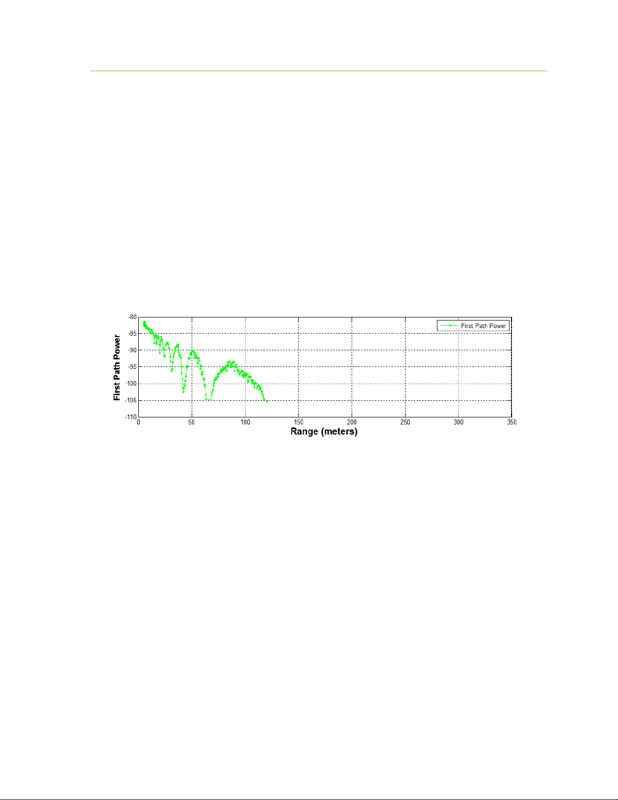
The ability to log data also allows the user to plot performance as a function of range. This is an
excellent tool for evaluating signal propagation in a given area. For example, the information shown
in Figure 2-1 was collected as the distance between two units was increased. Basically, data was
logged with one unit held stationary while the second unit was driven away. Figure 2-1 is a plot of
the received signal strength (First Path Power) as a function of separation distance. In this figure one
can observe several items of note:
There is a major Fresnel cancellation at 60and 130 meters as well as minor ones between 20
and 40meters.
The minimum sensitivity of this unit is -105db.
Fig. 2-1: Received signal strength (First Path Power) as function of separation distance.
2.4.2 Networking and Localization with RangeNet
Operating a system that consists of only two units is very simple. Operating with more than two units
starts to introduce significant complexity which is increased even further when the need to determine
location is added. For example:
There needs to be a way to prevent units from interfering with each other.
The number of radios in the system may vary with time. Units that enter the system need to
be discovered. Units that exit the system need to be removed from the network.
Not all units need to behave the same way. Some units might initiate and respond to range
measurement requests. Some might only initiate requests. Some might only respond. Some
units might only communicate with a subset of the system.
Before you can convert range into location it is necessary to define a coordinate system and
measure the position of anchor (fixed reference) units relative to that system.
The X,Y,Z location of the references needs to be communicated with all of the anchors.
Since ranges are taken while a unit is moving, simple trilateration may not produce valid
locations. It is therefore necessary to include in the location solving engine a Kalman Filter
to both filter out noise and better compute locations.
DRAFT

12 P330 Data Sheet / User Guide
The RangeNet API allows the user to define a network and to define the behavior of the radios in the
system. Operation of the network is controlled by the P330. In particular, the P330 is responsible for
scheduling range requests, maintaining all of the neighbors in a database, and passing data between
the Host and the network. The Host computer function is thereby limited to monitoring and
supervision, thus significantly offloading its responsibilities.
The RangeNet API provides the user with tools to define and monitor the network. For example:
The network can be defined using two different time-sharing protocols: ALOHA
(randomized) or TDMA (Time Division Multiple Access).
If the ALOHA protocol is used, then the average interval and the random variation of that
interval can both be defined. The average interval can be manually or automatically throttled
based on the number of units in the system. Radio behavior can be limited on a per unit basis
such that some units initiate and respond to range requests, while others initiate-only or
respond-only. In addition, some units can be instructed to limit their interactions to a subset
of the network members. While most ALOHA networks have an efficiency of 19%, the
efficiency of this ALOHA network is approximately 38%, making it equivalent to the
performance of a Slotted ALOHA system.
If the TDMA protocol is used, then the user can define a slot map that provides each radio
with instructions on when and to whom and with what parameters it should communicate.
Because the P330 supports multiple communications channels, it is possible to operate either
the ALOHA or TDMA protocol with a CDMA overlay.
Because the P330 network schedules range requests, it avoids the overhead of Host to P330
communications and can therefore run at a higher ranging rate.
The P330 network maintains a neighbor database. Besides noting all of the members of the
network and their ranges, this database also contains a large body of statistics and other
useful information. For example, the database includes received signal strength, approach
velocity, effective ranging rate, and signal quality.
The RangeNet API also provides the user with the ability to enable the P330s to compute their
location based on ranges generated by the network. This capability does not limit the user’s ability to
independently construct a Host based localizer.
The P330 API supports three localization modes: IDLE (awaiting instructions), Autosurvey
(anchors use UWB ranging to self locate) and Tracking (P330s compute position in the
system and report)
The API allows the Host to connect to any unit and use that connection to report the location
of any unit in the system as well as all of the range measurements taken in the system.
Based on instructions from the user, the P330 will compute either X and Y locations or X, Y
and Z locations, variance and covariance information and report those values through the
API.
While these are all powerful network tools, the complexity inherent in this richness can make it
difficult to visualize operation through just the API. The RangeNet GUI fills this gap. Not only does
the RangeNet GUI allow the user to configure the system, but it also provides a means for easily
maintaining different configurations, monitoring results, evaluating the performance of individual
links in the network, monitoring the neighbor database, reporting location information and quality
statistics from all units in the system. For example, the RangeNet GUI allows the user to:
Define all types of configuration information (including TDMA slot map, ranging
DRAFT

P330 Data Sheet / User Guide 13
configuration details, ALOHA setup information, neighbor database characteristics),
download it to the P330, store that configuration to disk, and recover from disk any given
configuration.
Monitor the database at whatever update rate the user finds useful.
Send, receive, and display data.
Display waveform scans, range measurements and location measurements as well as
relevant metrics and statistics associated with a particular links.
While all the functions mentioned so far are performed by the P330 processor and reported to the
GUI, additional location related capabilities have been included in the RangeNet GUI. For example:
The Autosurvey capability has been implemented through the RangeNet GUI. When
engaged, the units in the system will be ordered to range to each other and these ranges will
be reported to the GUI. The GUI will compute anchor locations until such time that the
standard deviation of the location measurements has achieved a user defined threshold.
Once the locations of the anchors have been defined (either through Autosurvey or manual
survey with a laser theodolite) the GUI will then broad cast locations information to all of the
units in the system. The P330 based network uses a flooding algorithm to distribute this
information through the system and an active confirmation system to verify that the
information has been successfully distributed..
Once the system transitions to Tracking Mode, the GUI will display, in real time, the location
of all of the units in the system.
The GUI also allows the user to define, display and add GPS like waypoints to the system.
2.5 Networking: RangeNet vs. RangeNet Lite
RangeNet Lite is a node-limited version of RangeNet and is intended to allow users to evaluate and
test before considering licensing or purchasing the unrestricted version. RangeNet Lite is provided
with all Ranging and Localization Development Kits, as well as the PulsON Lab and MegaLab
packages. It is node-locked in that the Lite version will support all of the features of RangeNet as
long as the system size is limited to 10 nodes or less. More specifically, the first 10 nodes that join
the system will operate normally. They can join and leave the network normally, but the 11th unit
and all subsequent units will not be recognized by the system. These units will still operate but will
likely interfere with the first 10 units and significantly degrade network performance for the first 10
units.
For information on upgrading from RangeNet Lite, please contact Time Domain directly at
sales@timedomain.com.
2.6 Software & Hardware Support
Time Domain is committed to maintaining full-featured software support for the hardware platforms.
We believe that the success of UWB will be largely determined not by the capability of the hardware
but by the richness of the software which drives the hardware. This includes improvements to both
the embedded software (where the basic functionality of the UWB technology can be changed) and
the API interface (where upper layers can be added).
It is Time Domain’s intention to continue increasing the capability of UWB by adding new and
DRAFT

14 P330 Data Sheet / User Guide
significant software functionality.
For example, consider recent releases:
2010 – Ranging capability demonstrated with P400
2011 – Monostatic radar functionality added
2012 – Ranging performance enhanced
2013 – Channel analysis and bistatic / multistatic radar functionality added
2014 – RangeNet, a networking capability based on the ALOHA and
TDMA protocol, added
2015 – RangeNet Lite added
2016 - Localization layer added to RangeNet
Support for Decawave DW1000 added to Rangenet
It is Time Domain’s intention to continually increase the capability of UWB by adding new and
significant software functionality.
DRAFT
P330 Data Sheet / User Guide 15
DW1000
RF Port A
Processor
FPGA
P330
UWB Antenna
Temp
Serial
USB
USB Data Jack
Ethernet Jack
Ethernet
Can
J9
J5
Regulators
5-48Volts
Flash
and RAM
Memory
Blue LED
38.4MHz
Osc
USB Power Jack
SPI (5)
3.3V GPIO (3)
3.3V GPIO (3)
J10 User Mezzanine
- VCC_Main
- Power Enable
- Supply Ground
- Digital Ground
- SPI (5)
- Serial
- CAN
- ARM 3.3V GPIO (2)
- FPGA 3.3V GPIO (2)
J11 Locking Connector
- VCC_Main
- Supply Ground
- Digital Ground
- SPI (5)
- Serial
- CAN
- ARM 3.3V GPIO (1)
- FPGA 3.3V GPIO (3)
Power Enable
Ethernet RMII
J13
J8 Ethernet Mezzanine
- Digital Ground
- Ethernet
- ARM 1.8V GPIO (2)
- Ext 16MHz CLK (reserved)
1.8V GPIO (2)
1.8V GPIO (2)
J6 Factory Mezzanine
- Digital Ground
- FPGA 1.8V GPIO (2)
- ARM 3.3V GPIO (1)
- Factory Reserved
Chassis Ground
VCC_Main
Green LED
UWB Components
Non-UWB Component
User Interface
LEDs (4)
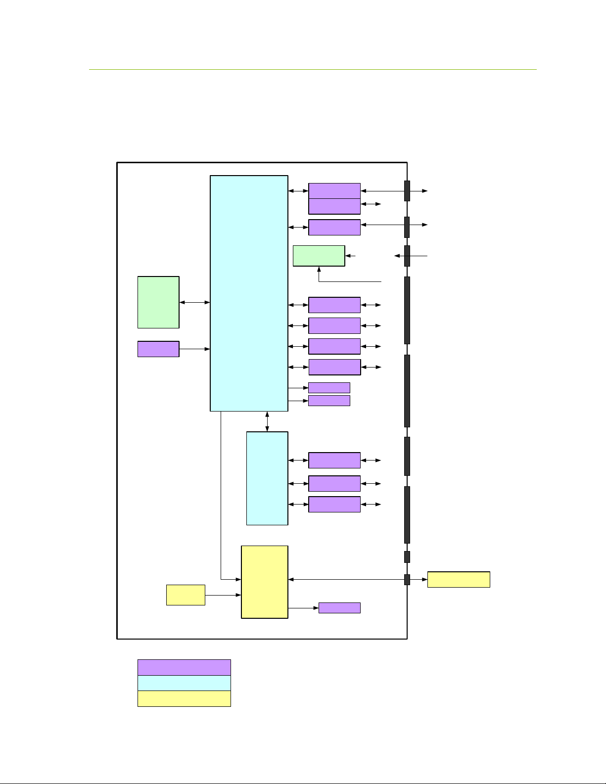
3 Hardware Block Diagram
This section provides and discusses at a high level the P330 functional hardware block diagram
shown in Figure 3-1. Additional detail on the various interfaces is provided in Section 4.
Fig. 3-1: P330 hardware functional block diagram
DRAFT

16 P330 Data Sheet / User Guide
The P330 requires less than a Watt of power from a DC supply that provides any voltage between 5.5
and 48 volts. This power can be provided through Time Domain’s standard external power supply, a
battery, or a user-supplied power source. Indicator lights provide operating status information.
The processor monitors and controls the DW1000, initiates range requests, controls the flow of data
to and from the DW1000, operates the network, computes locations and handles the interface with the
host/user.
The DW1000 is a full UWB transceiver. It transmits and receives packets, sends data, initiates Two
Way Time of Flight Range measurements and reports the range measurements as well as several
statistics related to the measurement.
The user can interface to the P330 through Ethernet, USB, SPI, Serial, or CAN. Ten GPIO pins are
available. If the SPI interface is not used, then these pins can be reassigned yielding an additional
five GPIOs for a total of 15.
In addition, the user can request that the P330 report the board temperature.
A variety of means have been provided to physically interface to the P330. These means include two
USB connectors, an Ethernet RJ45 connector, a locking connector, and three mezzanine connectors.
See Section 4 for details. The mezzanine connectors are suitable for mating directly with a customerprovided board. Mating mezzanine connectors can be ordered with a variety of mated heights,
thereby allowing the user to mount low profile devices on their carrier board underneath the P330.
See Section 5 for details.
DRAFT
 Loading...