

Human HumaStar 600 User Manual
HumaStar 600
|
User Manual
Cat No. 16660/001


REVISION LIST OF THE MANUAL
Rev. /DATE. REVISION DESCRIPTION
01/2007-09 First edition
02/2007-11 Correction of typing errors
03/2008-03 New features of SW 1.7.1 implemented
04/2008-10 New features of SW 1.7.3 implemented
(calibration status, reagent status, ISE module update)
05/2009-01 Typing errors corrected
06/2010-05 New features of SW 1.8.1 implemented
(clot detection, power user, wear, BCR for controls and standards)
07/2011-06 Update for software 1.8.1 r2011.05.30
08/2011-09 Correction dimension
09/2014-12 Adding of System Wash Solution, chapter of ISE module excluded
10/2017-05 Update for Software 2.5.0
SYSTEM VERSION
COPYRIGHT
Copyright 2017, Human Gesellschaft für Biochemica und Diagnostica mbH, Wiesbaden, Germany. All rights reserved.
No part of this documentation may be reproduced in any form, nor processed, copied or distributed by means of electronic systems, without prior permission of Human GmbH in writing. Since
all precautionary measures were taken into account in producing these operating instructions,
the manufacturer accepts no responsibility for any errors or omissions. This includes any liability
for damage that could arise from possible incorrect operation based on this information. Subject
to changes without notice as result of technical development.
SERVICE UND SUPPORT


CONTENTS
TABLE OF CONTENTS
1 SAFETY INSTRUCTIONS 5
1.1 INTRODUCTION 5
1.2 USER WARRANTY 5
1.3 INTENDED USE OF THE INSTRUMENT [IVD] 6
1.4 GENERAL SAFETY WARNINGS 6
1.5 DISPOSAL MANAGEMENT CONCEPT 7
1.6 INSTRUMENT DISINFECTION 7
1.7 BIOHAZARD WARNING 8
1.8 ADDITIONAL LABELS 8
2 INTRODUCTION 9
3 SYSTEM DESCRIPTION 11
3.1 UNPACKING 11
3.2 INSTALLATION 11
3.2.1 Installation Requirements 11
3.2.2 Electrical connections 12
3.2.3 Hydraulics 12
3.2.4 Handling of biological fluids 13
3.2.5 Computer setup 14
3.2.6 Parameters 15
3.2.7 Tools 23
3.3 PARTS OF THE INSTRUMENT 28
3.3.1 Front view 28
3.3.2 Top view 28
3.3.3 Left side 29
3.3.4 Samples and sample sectors 29
3.3.5 Reagents 30
3.3.6 Barcodes 30
3.3.7 Cuvettes 30
3.4 SOFTWARE FUNCTIONS OVERVIEW 31
3.4.1 Levels of access 31
3.4.2 Data menu 32
3.4.3 Main Screen 33
3.4.4 Quick Key Menus 36

4 GET READY FOR OPERATION 41
4.1 AUTOMATIC OPERATION 41
4.1.1 Clot detector 42
5 ROUTINE TASKS 43
5.1 REAGENTS 43
5.1.1 Reagent tray 43
5.1.2 Loading barcoded reagents, Diluent and Cleaning Solutions 44
5.1.3 Loading non barcoded reagents and solutions 45
5.1.4 Removing reagents and solutions 45
5.1.5 Refilling reagent bottles (only for open channels) 47
5.1.6 Method assignment to trays 47
5.2 SAMPLES 47
5.2.1 Working with patients 48
5.2.2 Defining sample data and tests 49
5.2.3 Removing a sample 50
5.2.4 Removing tests 51
5.2.5 Copy data 51
5.2.6 Loading samples 52
5.2.7 Removing a sample 53
5.2.8 Placing a sector on the tray 53
5.2.9 Removing a sector 54
5.2.10 Loading a STAT 54
5.2.11 Reports 55
5.3 TEST RESULTS 56
5.3.1 Acceptance of Results 57
5.3.2 Reflex Tests 57
5.3.3 Printout of results 57
5.3.4 Cuvette 57
5.4 CALIBRATION 58
5.4.1 Calibrator sets 59
5.4.2 Requesting a calibration 61
5.4.3 Ordering a calibration 63
5.4.4 Calibration acceptance 63
5.4.5 Automatic calibration 64
5.5 REAGENT BLANK 65
5.6 QUALITY CONTROL 67
5.6.1 Creating a control set 69
5.6.2 Requesting a control 71
5.6.3 Processing a control 72

CONTENTS
5.6.4 Processed controls 72
5.7 TWIN QC 75
5.7.1 QC scheduler 78
5.8 WORKING WITH LIS 80
5.9 DEFINITION AND USE OF SAMPLE PROFILES 80
5.9.1 Defining a sample profile 80
6 DEFINITION OF METHODS 81
6.1 METHOD TYPES AND CALCULATIONS 81
6.1.1 Endpoint 82
6.1.2 Fixed Point 83
6.1.3 Kinetics 84
6.2 METHOD PARAMETERS 84
6.2.1 Common parameters 84
6.2.2 Main Page 85
6.2.3 Quantitative 88
6.2.4 Limits 89
6.2.5 Reference classes 91
6.2.6 Advanced features 92
6.2.7 Consumption 94
6.2.8 Reagent substitution 95
6.2.9 Kits 96
6.3 SOLUTIONS 97
6.4 OPTIONS 98
6.5 CALCULATED METHODS 99
6.6 EXTERNAL METHODS 100
6.7 UNITS AND LIMITS 101
6.8 DEVELOPEMENT OF A METHOD 101
7 ISE MODULE CAT.-NO. 16663-03 103
8 MAINTENANCE 105
8.1 SCHEDULER 105
8.1.1 Schedule 106
8.1.2 Status 107
8.2 DAILY MAINTENANCE 108
8.2.1 Inspection and Cleaning of Probes 108
8.2.2 Check and Replace System Solutions 108
8.2.3 Empty Waste Bottle 109
8.2.4 Hydraulic Testing – System Flush 109

8.3 WEEKLY MAINTENANCE 110
8.3.1 Intensive Cuvette Cleaning 110
8.3.2 Cuvette Water Blank 111
8.3.3 Service Backup 111
8.4 MONTHLY MAINTENANCE 112
8.4.1 Photometer Calibration 112
8.4.2 Washer Volume Calibration 113
8.4.3 Clean System Bottles 114
8.4.4 Intensive Washer Cleaning 115
8.5 MAINTENANCE ON DEMAND 116
8.5.1 Cuvette Change 116
8.5.2 Lamp Replacement 117
8.5.3 Pump tube replacement 117
8.6 COUNTERS 117
9 TROUBLESHOOTING 119
9.1 MESSAGES AND WARNINGS 119
9.2 VISIBLE FAULTS 119
9.2.1 General faults 119
9.2.2 Measurement inconsistencies 120
10 APPENDIX 123
10.1 TECHNICAL SPECIFICATION 123

Safety InStructIonS 5
1 SAFETY INSTRUCTIONS
1.1 Introduction
This manual is considered as a part of the instrument; it has to be at the oper-
ator’s hand as well as at the maintenance operator’s availability. For accurate
installation, use and maintenance, please read the following instructions carefully. In order to avoid instrument damage or personal injury, carefully read the
”GENERAL SAFETY WARNINGS”, describing the suitable operating procedures. In
case of breakdowns or any troubles with the instrument, apply to the local Technical Service.
1.2 User Warranty
HUMAN warrants that instruments sold by one of its authorised representatives shall be free of any defect in material or workmanship, provided that this
warranty shall apply only to defects which become apparent within one year
from the date of delivery of the new instrument to the purchaser.
The HUMAN representative shall replace or repair any defective item at no
charge, except for transportation expenses to the point of repair.
This warranty excludes the HUMAN representative from liability to replace any
item considered as expendable in the course of normal usage, e.g.: lamps, valves,
syringes, glassware, fuses, diskettes, tubing etc.
The HUMAN representative shall be relieved of any liability under this warranty
if the product is not used in accordance with the manufacturer‘s instructions,
altered in any way not specified by HUMAN, not regularly maintained, used with
equipment not approved by HUMAN or used for purposes for which it was not
designed.
HUMAN shall be relieved of any obligation under this warranty, unless a com-
pleted installation / warranty registration form is received by HUMAN within
15 days of installation of this product.
This warranty does not apply to damages incurred in shipment of goods. Any
damage so incurred shall be reported to the freight carrier for settlement or
claim.

6
1.3 Intended Use of the Instrument [IVD]
The instrument is intended for in vitro diagnostic application by professional
users. It has to be used for the expected purposes and in perfect technical conditions, by qualified personnel, in working conditions and maintenance opera-
tions as described in this manual, according to the GENERAL SAFETY WARNINGS.
This manual contains instructions for professional qualified operators.
The external PC must not be used for purposes other than those designated in
this manual. The analyzer is designated for indoor use only. Recommendation
provided in the leaflet for all reagents and consumables have to be observed.
1.4 General Safety Warnings
Use only chemical reagents and accessories specified and supplied by HUMAN
and/or mentioned in this manual. Place the product so that it has proper ven-
tilation.
The instrument should be installed on a stationary flat working surface, free
from vibrations.
Do not operate in area with excessive dust.
Work at room temperature and humidity, according to the specifications listed
in this manual.
Do not operate this instrument with covers and panels removed.
Only use the power cord specified for this product, with the grounding conduc-
tor of the power cord connected to earth ground.
Use only the fuse type and rating specified by the manufacturer for this instru-
ment, use of fuses with improper ratings may pose electrical and fire hazards.
To avoid fire or shock hazard, observe all ratings and markings on the instru-
ment.
Do not power the instrument in potentially explosive environment or at risk of
fire.
Prior to cleaning and/or maintaining the instrument, switch off the instrument
and remove the power cord.
For cleaning use only materials specified in this manual, otherwise parts may
become damaged. It is recommended always to wear protective apparel and eye
protection while using this instrument. Respective warning symbols, if appear-
ing in this manual, should be carefully considered.
HumaStar 600 | User manual

Safety InStructIonS 7
1.5 Disposal Management Concept
The currently valid local regulations governing disposal must be observed. It is in
the responsibility of the user to arrange proper disposal of the individual components.
All parts which may comprise potentially infectious materials have to be disinfected by suitable validated procedures (autoclaving, chemical treatment)
prior to disposal. Applicable local regulations for disposal have to be carefully
observed.
The instruments and electronic accessories (without batteries, power packs etc.)
must be disposed off according to the regulations for the disposal of electronic
components.
Batteries, power packs and similar power source have to be dismounted from
electric/electronic parts and disposed off in accordance with applicable local
regulations.
1.6 Instrument Disinfection
Analytical instruments for in vitro diagnostic involve the handling of human
samples and controls which should be considered at least potentially infectious.
Therefore every part and accessory of the respective instrument which may have
come into contact with such samples must equally be considered as potentially
infectious.
Before doing any servicing on the instrument it is very important to thoroughly disinfect all possibly contaminated parts. Before the instrument is removed
from the laboratory for disposal or servicing, it must be decontaminated. Decontamination should be performed by authorised well-trained personnel only,
observing all necessary safety precautions. Instruments to be returned have to
be accompanied by a decontamination certificate completed by the responsible
laboratory manager. If a decontamination certificate is not supplied, the returning laboratory will be responsible for charges resulting from non-acceptance of
the instrument by the servicing centre, or from authority’s interventions.
8
Biological Hazard Symbol
1.7 Biohazard warning
Analytical instruments for in vitro diagnostic application involve the handling
of human samples, calibrators and controls which should be considered at least
potentially infectious. Therefore every part and accessory of the respective in-
strument which may have come into contact with such samples must equally
be considered as potentially infectious.
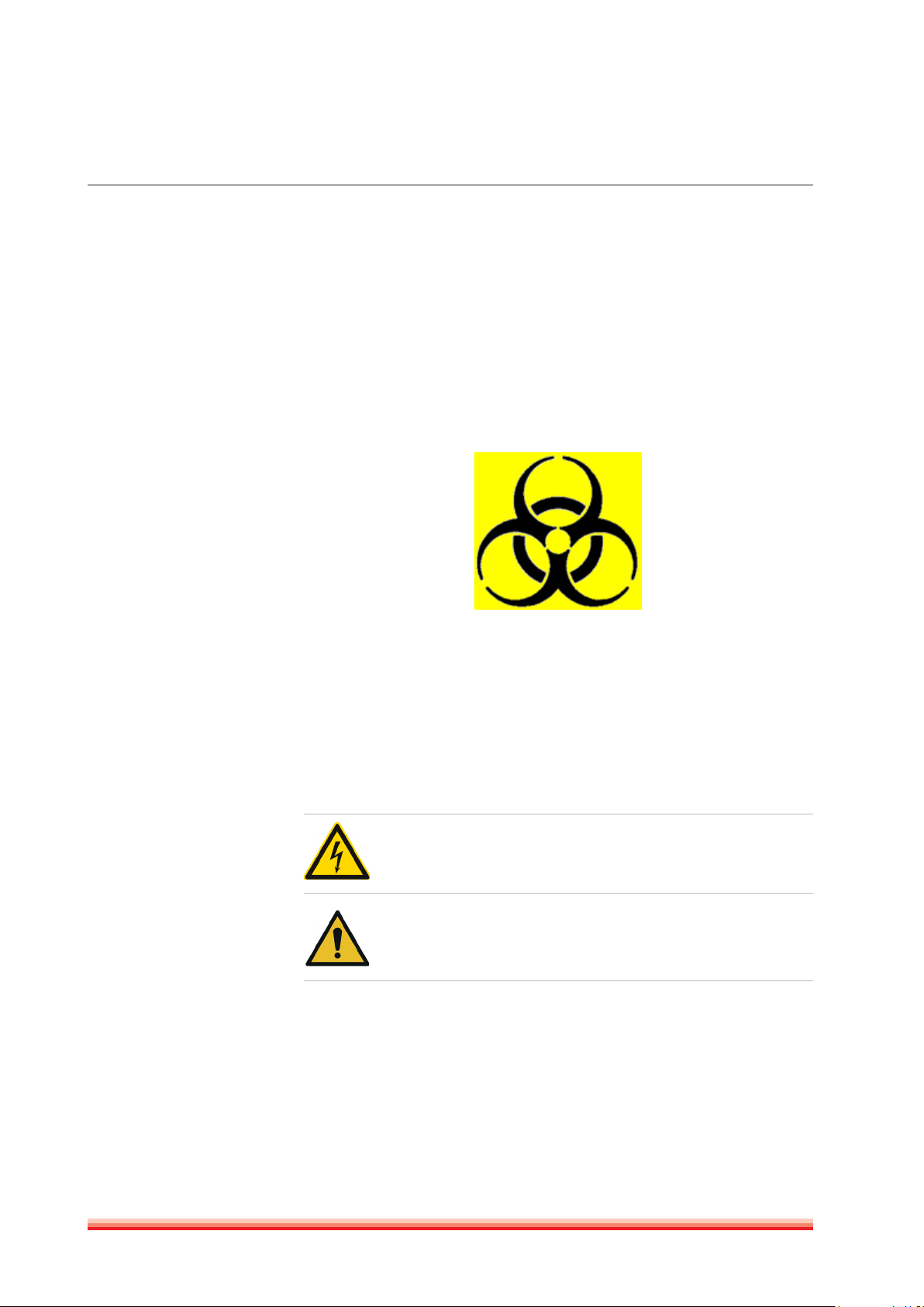
For safety reasons, we have labeled instruments with the „BIOHAZARD“ warn-
ing label below.
FIGURE 1
1.8 Additional Labels
The labels used on Human products are among those specified by the interna-
tional Organisation for Standardization (ISO).
They are placed at critical points on each instrument as a warning of the risks
involved.
While operating any of our instruments take note of these and observe the
precautions described.
Warning Electrical Risk - This label indicates the operator of the
presence of high electrical voltage.
Warning Danger: This label indicates a potential hazard which, if not
avoided, can result in injury to an operator and/or serious property
damage. Please read the manual for instructions before opening.
HumaStar 600 | User manual

IntroductIon 9
2 INTRODUCTION
The HumaStar 600 is a reliable in vitro diagnostic chemistry analyzer for auto-
matic testing of routine clinical chemistry tests and electrolytes.
Being real random access, this HumaStar 600 is the ideal solution for medium
to large size labs, with a throughput of more than 600 photometric tests/hour
(720 tests/hour with ISE).
Continuous process can be achieved as samples sectors can be loaded quickly and simply allowing nonstop operation. Sectors can hold primary tubes and
small sample cups.
Refrigerated reagent tray can hold up to 48 different containers ranging from
20 to 70ml depending on configuration.
The optional ISE unit gets electrochemical measurement of Na+, K+ and Cl- elec-
trolytes with automatic urine sample dilution. The instrument is controlled
by a PC workstation that has graphical -user friendly- interface software. The
software provides total control over the analyzing process and gives easy ac-
cess to advanced statistical functions and reports. Versatile method setup com-
prises end point, fixed point, kinetics, ISE, coagulation, calculated and externals.
Optional features include:
- Flexible pre- and post washing for each test to prevent carryover.
- Auto rerun with automatic dilution of samples which are out of linear range.
- Automatically duplicate for result confirmation
- Extra volume dispensing of water or reagent to improve accuracy.
- Reagent integrity check for safe operation.
- Automatic predilution for calibrators, controls, blanks and samples to fit any
method insert.
- Curve and linear calibration with unlimited number of standards for highest
accuracy.
- Onboard sample and reagent bar code reading assure positive identification.
- Capacity sensor monitors sample and reagent volumes.
- Instant mixing during dispense gives precise initial reaction time.
- Automatic acceptance of calibrators, control and samples increase the walk
away time.
- Current activity monitor screen indicates to the operator when the routine
will be finished
- Clot detector
- Low water consumption.

10
HumaStar 600 | User manual

SyStem deScrIptIon 11
3 SYSTEM DESCRIPTION
3.1 Unpacking
Remove all the parts from their package.
When unpacking the instrument, please make sure that the following items are
contained in the packing. In case of damage or missing item, please contact the
supplier immediately.
Quantity Description
1 Software CD 16661
2 Reaction cuvettes (box of 1200) 16661/1
2 Drying block kit 16661/11
1 Reagent recipients with cap (x 30) vol. 70 ml 16661/2
1 Reagent recipients with cap (x 30) vol. 25 ml 16661/3
2 Peristaltic Pump tubing kit x 3 16661/4
2 Sample tubes 13 mm. kit x 100 16661/5
1 Halogen lamp 12V 20W 16661/7
5 Sample Rack 16661/15
1 Serial Cable 16661/16
1 User Manual 16660/001
[REF]
3.2 Installation
3.2.1 INSTALLATION REQUIREMENTS
Carefully read the safety instructions included in this manual.
Install the instrument on a hard floor with a resistance of at least 50 kg/cm2; use,
if possible, ceramic or stone floor.
Avoid carpets or very soft rubber.
Mains should be close to the instrument (less than two meters) and must fulfill
local regulations.
Free access to main switch is required. A distance of 50 cm from the left side
of instrument to nearest table or wall is advisable. Right side must have a free
space of at least 30 cm for ventilation purposes.
Space must be empty over instrument to 2.10 m. Avoid using shelves, walls or
screens above instrument.
Instrument is mounted on wheels and can be moved towards the front for servicing and cleaning purposes. Allow free space of about two times the instrument depth.
TABLE 1

12
Instrument is Installation Cat-
egory II. Instrument requires
protective ground connection.
Verify ground connection before
installing the instrument.
User must be warned about
the use of instrument under
abnormal grounding conditions.
It is advisable not to complete in-
stallation under poor ground con-
ditions.
Preparation of System Wash
Solution IFU of Wash Add
Ref 18971.
3.2.2 ELECTRICAL CONNECTIONS
Plug in the mains cord to a socket with ground connection. The power requirements for the HumaStar 600 are as follows: 100~240 VAC, 50/60 Hz, 1400 VA
maximum.
Maximum voltage between ground and neutral lead: 0.5 volts.
There is a J9 serial port type RS232C connector in the rear part of the instrument.
Connect the HumaStar 600 to the computer serial port using the provided cable.
Tighten retaining screws.
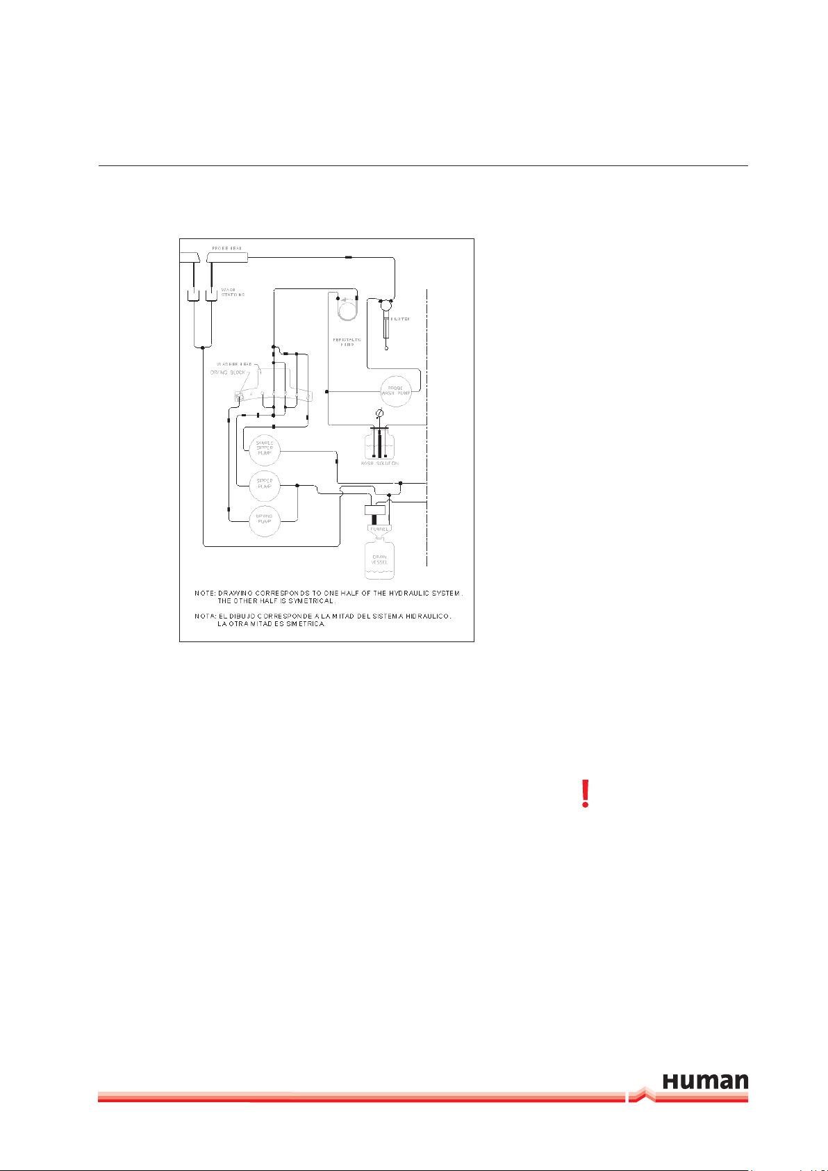
3.2.3 HYDRAULICS
The waste deposit collects the drainage of the probe washing stations and
occasional waste from the dispensing stations and cuvette washers. Place the
emptied bottle in the correct location and orientation (see Figure 23).
Pay attention that the funnel is inside the bottle neck. The waste bottle has a
capacity of 20 L and the wash solution bottle of 10 L. To perpare the system
wash solution, purified water should be used with less than 2 µS/cm and less
than 100 CFU/mL to avoid contamination of the system with ions and bacteria.
Described specification fall in CLSI Type 2 water catergory.
Level metering is made by means of a load cell system (scale) for wash solution- and waste bottle. Warning messages will appear before the system wash
solution is empty and the waste bottle full.
Put the pump tubing of the washing pumps in place. Take out the plastic protection tube (typically yellow) from the probe arm‘s vertical shaft before operating.
The system is ready to use. Flush the system at least 3 times in order to ensure
that all bubbles have been removed from the tubing and syringe.
HumaStar 600 | User manual
SyStem deScrIptIon 13
FIGURE 2
3.2.4 HANDLING OF BIOLOGICAL FLUIDS
Before connecting wash and drain lines, be sure to remember and understand
regulations and cautions about potentially dangerous biological fluids.
Keep in mind the following considerations:
1. Due to the presence of biological fluids, some instrument areas are potentially dangerous. They are warned with the symbol see Figure 1.
Dispensing tips, reaction cuvettes and drain fluid bottle are the most endangered areas.
Never dispose potentially
dangerous fluids on public
drain system.
Refer to chapter 1.5.

14
1. Sample handling, drain fluid disposal and reaction cuvettes replacement
must be done with safety disposable gloves manufactured according local
regulations for biological fluids handling.
2. Drain fluid must be neutralized. The addition of 0,5 % Sodium Hypochlorite
is suggested.
3. Verify and use local regulations on discarding pathological fluids.
4. If instrument is to be translated to other location or stored for a long period,
perform at least 5 purge cycles, remove cleaning solution bottle and repeat
purge cycles until drain lines are empty. Neutralize and dispose drain fluid.
3.2.5 COMPUTER SETUP
Follow the instruction set of the computer‘s manufacturer to connect and operate the computer system.
The minimum requirements for the computer are:
TABLE 2
Processor Intel Core i3 or higher
Memory 4 Gb Ram
Video board Graphics Enging GeForce 8400 or equivalent
Monitor 17“ (VIS 15.7“)
Display resolution 1024x768 (vertical refresh > 70 Hz)
Colour quality 16 bits
Hard drive 500 Gb SATA 3 7200 rpm or better
CD-Drive CD-RW or DVD-RW or DVD-R
USB port 2.0 or higher
Keyboard 105-key Performance keyboard
Pointing device USB mouse
Soundcard Integrated 16 bit (optional)
Speakers (optional)
Network adapter Ethernet 10/100 Mbits
RS-232 serial port
Serial Port
Additional serial port for LIS connection, (USB to RS232
adapter – optional)
Operating system Win 7 (32 and 64 bit), Win 10 (64 bit)
Compatible printer Any Windows™ compatible printer maybe installed.
HumaStar 600 | User manual
The computer should be used only for the operation of the instrument. Any oth-
er programms beside the instrument software may cause instument malfunction and /or breakdown.
The visual effects to best performance.
Change the setting of the operating system. Under properties Advanced
options visual effects select “Adjust for best performance”.
SyStem deScrIptIon 15
Setting of the Anti Virus Software
We recommend the use of Anti Virus Software on the Personal Computer of the
HumaStar 600. The HumaStar 600 “Rayo” directory has to be excluded from the
scanning process. Please refer to the documentation of the Anti Virus Software
Don‘t use the predefined MS Windows folders.
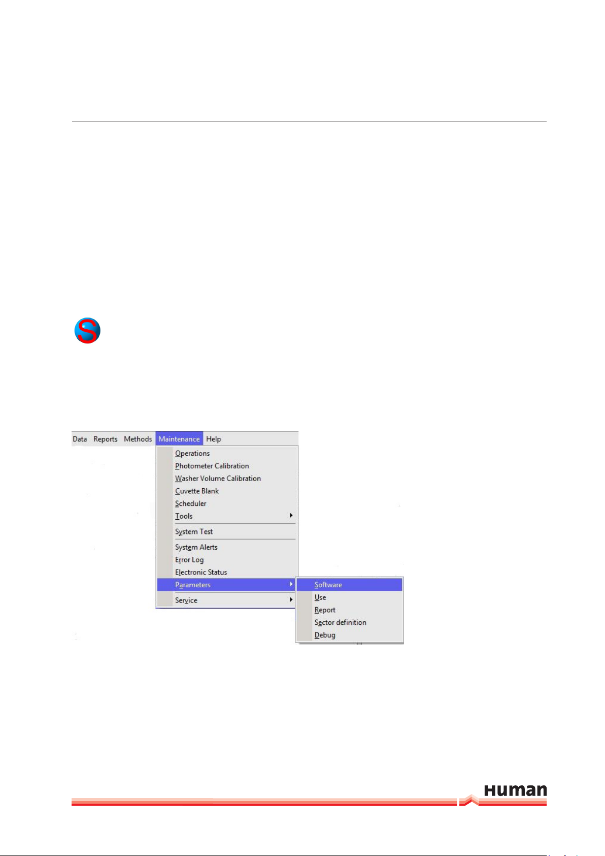
3.2.6 PARAMETERS
There are few parameters for software and instrument use accessible to opera-
tor. They are located in:
3.2.6.1 Software
Includes pages for communications, LIS and bar code reader.
FIGURE 3
16
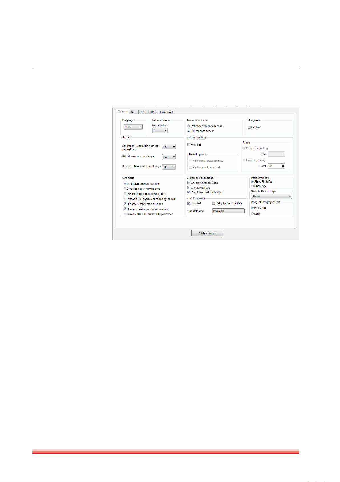
General
FIGURE 4
1. Communications: Select serial port according to your computer setting and
specification. If setting is wrong, the HumaStar 600 temporarily checks for
other port; but if no ports are free, program might not work properly.
2. Language: Select among languages already set in the translator. Changes
will come into effect when program is closed and re-opened.
3. Historic: Defines size in days and numbers that calibrators, controls and
samples will stay in ‘’upper’’ memory. Controls and samples above these
days will be stored at the cumulative historic files and can be recalled.
4. Random access: Two options are provided: batch and full random access.
5. Coagulation: (Service only - not in use):
6. Online printing: Enables printing; selector of printout of pending acceptance
samples and printout of manually accepted results.
7. Automatic: Selection of active warnings and software behavior on a number
of different routine analysis. ISE processing check can be enabled by default
with a parameter. The DI empty warning can stop dilutions if checked and
issue warning, but continue (with warning) if not checked.
8. Automatic acceptance: Sample results can be autoamtically accepted when
they are within the reference range, after an automatic repeat and/or when
a calibration is reused.
9. Patient window: Selection of display
10. Sample Default Type: Defines which sample type will be used as default on
the sample requistion screen.
HumaStar 600 | User manual
SyStem deScrIptIon 17
11. Reagent integrity check: run the reagent integrity check at each start of samples or only once a day.
12. Clot behavior: Enables the use of clot detection and offers additional options
in analyzer behavior in case that a clot is detected. Options: only flag - a flag
is added to the result, invalidate - the result will be deleted. The function to
aspirate the same sample again, can be enabled or disabled. Refer also to
section 4.1.1.
Press
Apply Changes
in order to save the changes.
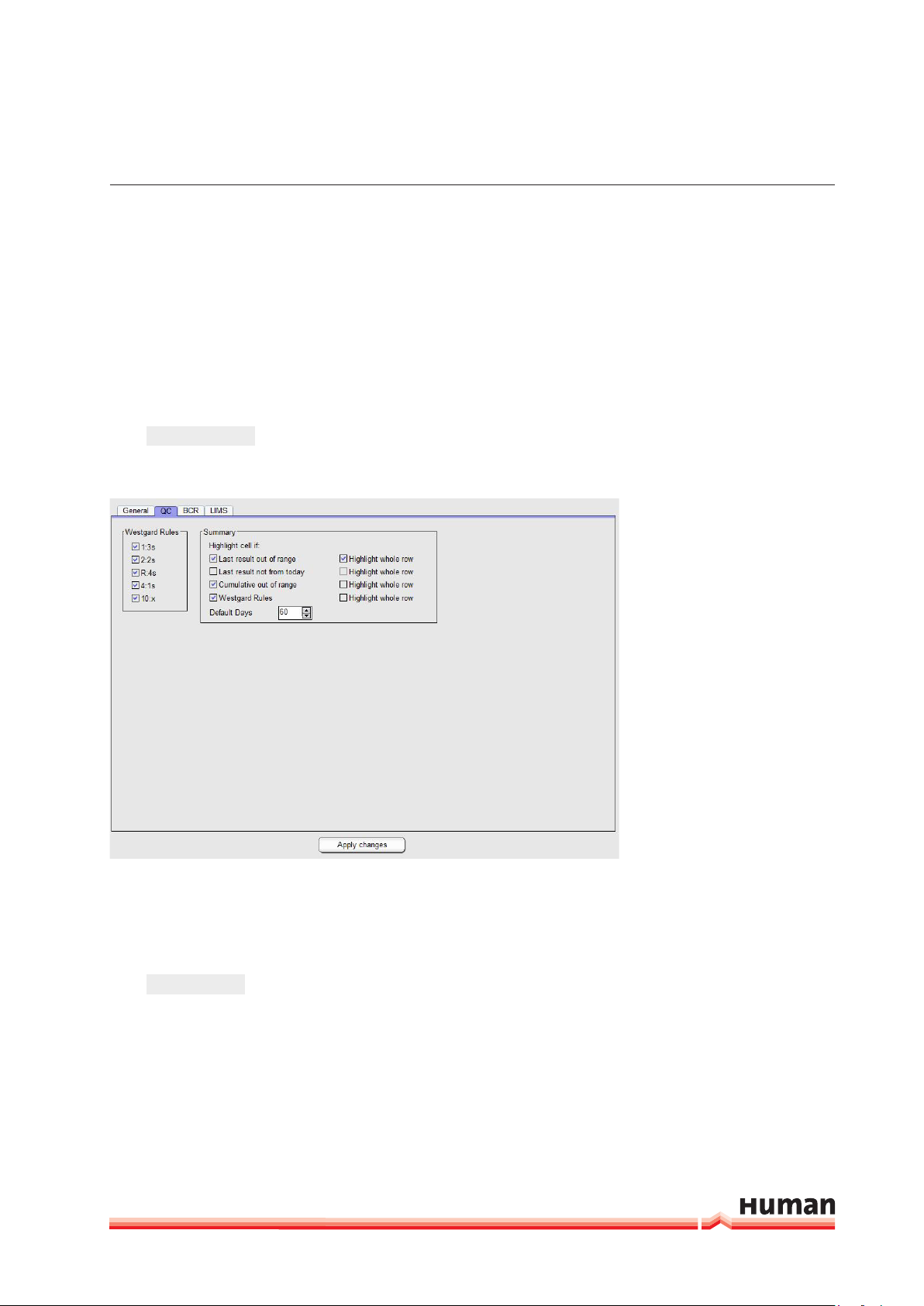
QC
FIGURE 5
1. Westgard Rules: options to select rules which should be evaluated at Levey
Jenning Plots at the “QC Done” window.
2. Summary: Option to select QC results which should be highlighted at the
“OC Statistics” window.
Press
Apply Changes
in order to save the changes.

18
BCR
FIGURE 6
1. BCR: Barcode reading can be activated for sectors, samples and reagents by
checking the corresponding box. When sectors are provided with bar code
identification, it is not necessary to define a number for sector loading.
2. Reagent configuration: Select setting according to your requirements. This
selector defines options for Method, bottle type, expiration date format and
starting position. In case of closed parameters, values are predefined and no
intervention is necessary.
3. Sample configuration: If Id position is not selected, all barcode digits are read.
4. Reagent no read behaviour: If reagent barcode is activated two options are
available for barcode reading error messages. The message can show up
each time an error accures or at the end of the reagent barcode reading.
5. Lot Number: To use multiple lots for the same reagent select the box “Mix
lots”.
Press
Apply Changes
in order to save the changes.
HumaStar 600 | User manual
SyStem deScrIptIon 19
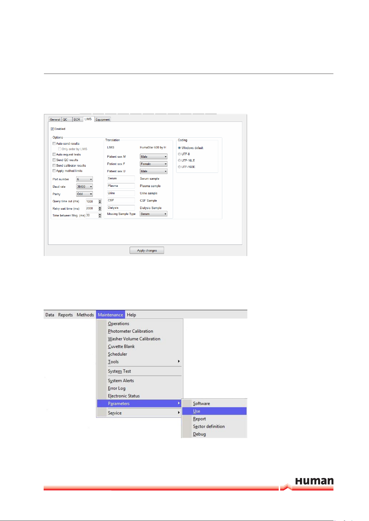
LIMS
FIGURE 7
1. Enabled: Select to activated and set informations for the communication
with host computer.
2. Options: Select parameters according to specifications of your LIMS provider.
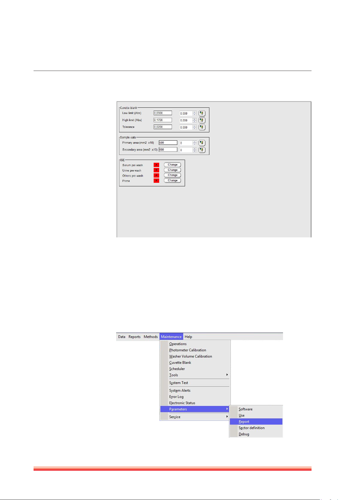
3.2.6.2 Use
Use parameters are split in several sections: Cuvette absorbance limits, ISE and
definitions of sample vials.
FIGURE 8
20
FIGURE 9
FIGURE 10
1. Cuvette blank: Upper- and lower limits for the cuvette check (air) can be set.
The tolerance value indicates the allowed absorbance variation of the first
reading after cuvette change and the actual reading.
2. Sample vials: Two different sample diameters vials can be defined. This fea-
ture is useful to define pediatric vials. Volume calculations require careful
section measurement for each defined vial.
3. ISE: Sample prewash can be enabled or disabled. For details, refer to ISE User
Manual REF 16663/1.
3.2.6.3 Report
HumaStar 600 | User manual
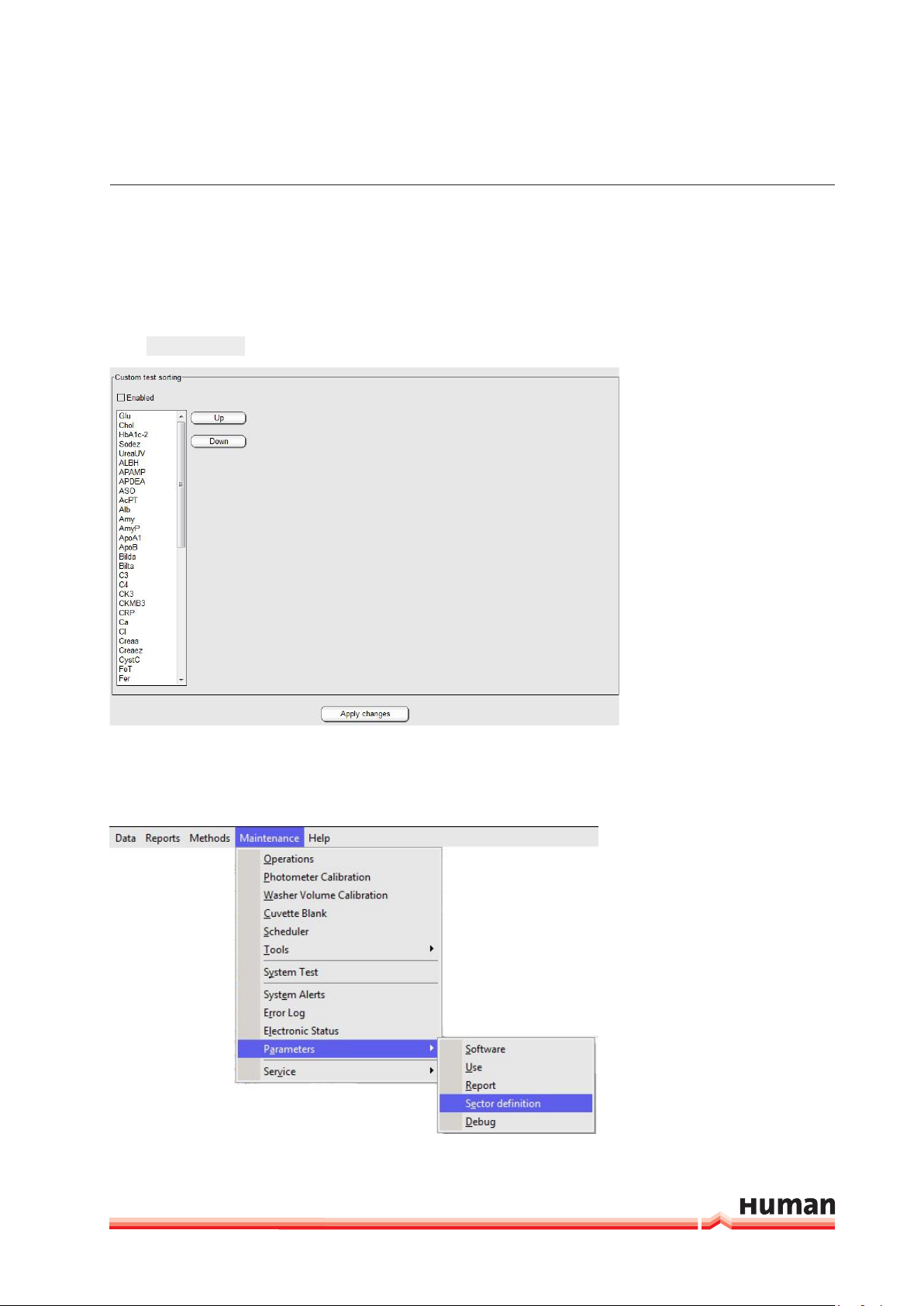
SyStem deScrIptIon 21
This section allows sorting how methods are ordered in report and printout. Keys
Up and Down allow moving methods to different positions in the final printout.
If not enabled, sorting will take place alphabetically.
Apply Changes
Press
in order to save the changes.
FIGURE 11
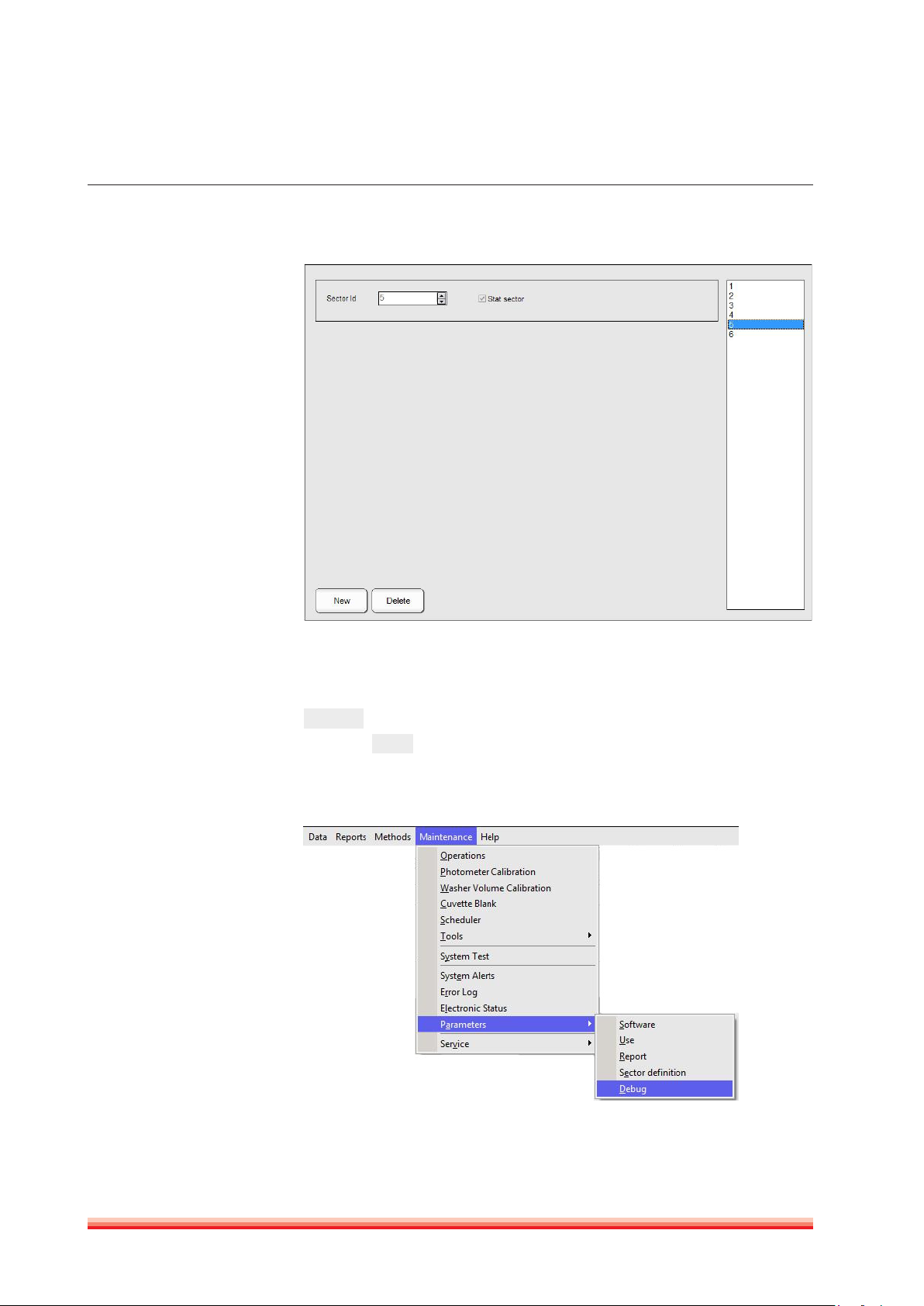
3.2.6.4 Sector definition
In this section user defines the number of sectors that are available on the
analyzer.
FIGURE 12
22
FIGURE 13
Up to 99 sample tray sectors can be programed and up to five can be on board
at the same time.
On the right side of the screen all programed sectors are displayed. Press
New
to add an other sector. To define it as a STAT, tick the box “STAT sector”
and press
. All samples placed on a STAT sector will be processed with
Ok
priority.
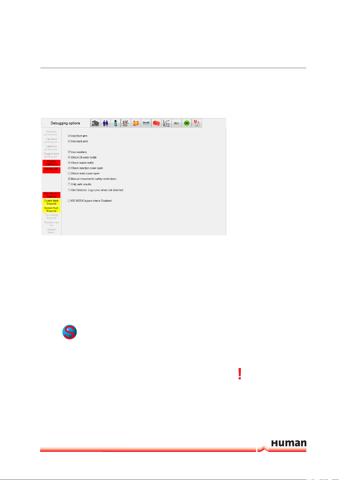
3.2.6.5 Debug
HumaStar 600 | User manual
SyStem deScrIptIon 23
In this section hardware and and hardware check functions can be activated or
deactivated.
FIGURE 14
To minimize down time following parts can be temporary deactiated: front- or
back arm and washer. In case the system is conneted to a water supply and
drain system the sensors for DI water and waste should be deactivated. During
routine use the reaction cover check should be activated. If the function “Only
safte results” is enabled, test with following flag: “wrong direction”, “initial absorbance limit”, “high consumption”, “correlation coefficient < 0.8” and “unstable ion” can not be accepted.
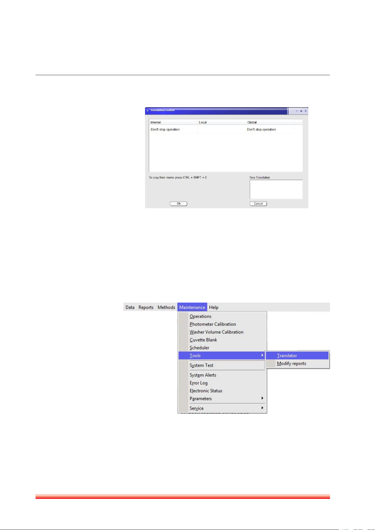
3.2.7 TOOLS
3.2.7.1 Translator
Translator operates on the language selected in Software parameters.
There are two basic ways of translating: translation control and dictionary.
Translation Control
To translate by translation control, place mouse pointer on the screen and
phrase whose translation must be modified; press keys Shift + Control + C. The
following screen will open:
Always end any modification
by pressing the
CTRL + SHIFT + C keys.
24
FIGURE 15
Left column is the Instrument Internal Language (mostly English); second and
third column are the present translation, if any. A new “Local” translation will
modify only the screen the Translation control window has been opened. All
modifications done in “Global” will effect all entries in the software.
Modifications take effect only when program is restarted. When a given translation is empty, system will use Internal language, no matter which language is
selected.
Translation with Dictionary:
FIGURE 16
HumaStar 600 | User manual
SyStem deScrIptIon 25
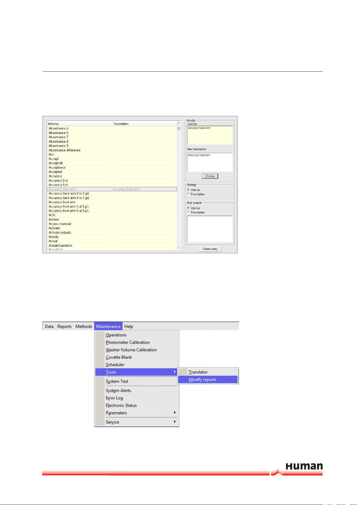
Translation can be done using the dictonary tool.
FIGURE 17
When any entry is selected, upper window shows internal text and lower window, the translation, if present. Sorting can be performed by internal or by
translation. There is also a built-in search tool. Entries can be deleted by pressing the corresponding button.
3.2.7.2 Modify reports
Customized report can be modified in
FIGURE 18
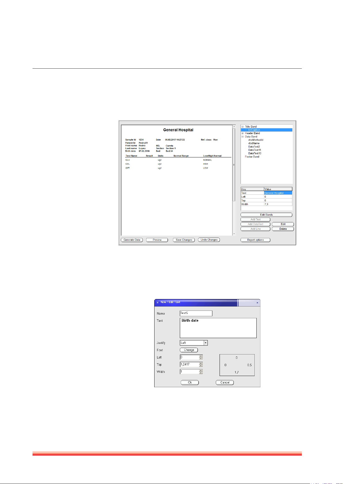
26
At top right there are four bands (title,header, data and footer) which split the
report in four separat sections:
FIGURE 19
FIGURE 20
To enable or disable a band use the function “Edit Bands”.
By clicking on the + button next to each band a variable number of additional
text captions will appear. It is possible to add, edit or delete text, data text or
lines for each band. Following screen will be open when the “Add” or “Edit” button is pushed. Text, position, size, font can be modified in this screen.
There are two types of fields: DataText are the Results written by instrument
once a value is printed. They can be moved, eliminated, changed font, etc. but
its text is out of operator‘s control. There also Report variables that can be added
HumaStar 600 | User manual
 Loading...