

Human HumaStar 300 Maintenance manual

Service Manual
!"#$%&$'()**
Cat.-No.: 17901S/2
!

,-./%/01(2/%3(04(3!-(561762
No. DATE / Rev. REVISION DESCRIPTION
1 01/2005-01 First edition
2 02/2005-08 Supplement: Technical diagrams
+

++

8013-13%
1. MECHANICAL ADJUSTMENTS 3
Reading Assembly 3
Sampling Arm 6
Cuvette Washing Arm 8
Photometer 9
Sample Tray 10
Reagent Plate 11
Diluters 12
Devices Required 13
2. ELECTRONICAL ADJUSTMENTS 14
3. OPERATIONS TO BE DONE WITH ANALYZER TURNED ON 16
4. UTILITY AND DIAGNOSTIC DISKETTE 16
5. TROUBLE SHOOTING GUIDE 17
6. HOW TO USE THE DIAGNOSTIC TESTER 21
%$9:&;(1<&:=
Analyzer may be contaminated with human material (blood, serum, plasma,
urine etc.) Disinfect analyzer prior to servicing and wear gloves. Be aware of
potential biohazardous risks!

3>+?(@$A:(B:9&(CB$DE
2/27 Service Manual HumaStar 300
FG(5-8!61/862(6HI7%35-13%
,-6H/1J(6%%-5K2L
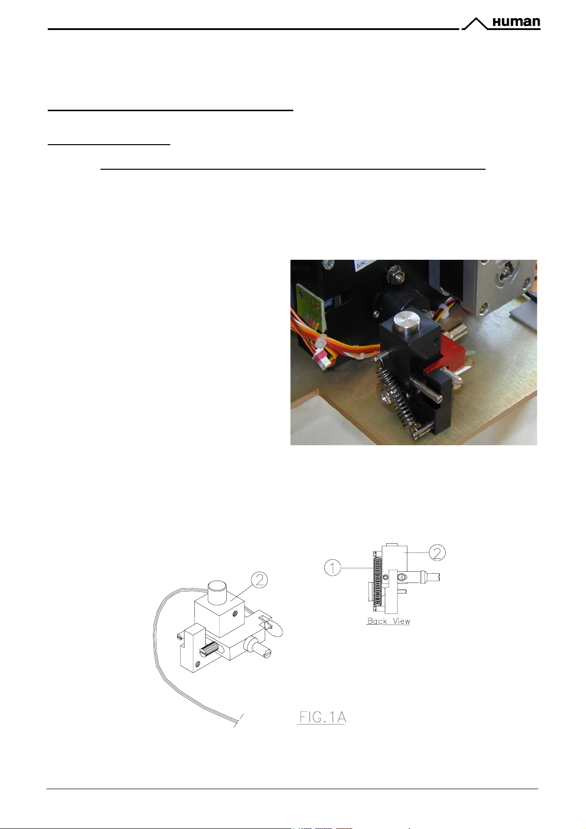
3!/%(0M-,63/01(?><"BN(C:(N<D:(O+&>(&>:(6162LP-,(37,1-H(044
1. Remove the lamp holder Fig. 1A: detach the spring (1) and remove the whole lamp support (2).
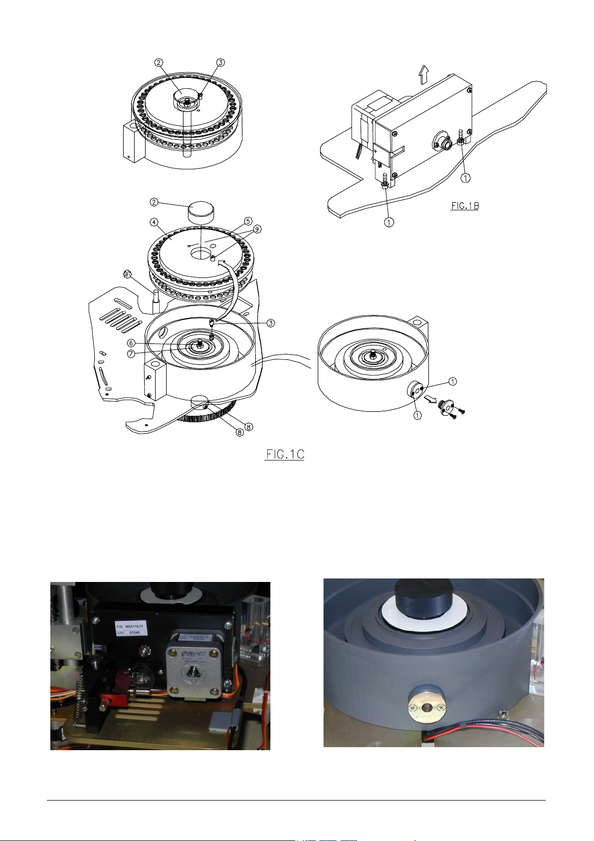
2. Remove the photometer Fig. 1B : remove the screws (1) ( hex key 3mm)
3. Remove the read window Fig.1C, remove the screws (1) ( use Phillips screwdriver 5mm)
4. Unscrew the knob (2), remove the reference pin (3). Remove the reaction plate. (To remove the
reaction plate use the reference pin by inserting it into one of the two holes (9) ). Remove cuvette
38 (use the extractor tool D/1)
5. Tighten the screw (6) ( hex key 10mm) to
lock the disk (7). Insert the Friction Devise
on the central axis on the side of the pulley
Fig. 1E. and loosen the screws (4) of the
pulley (2).
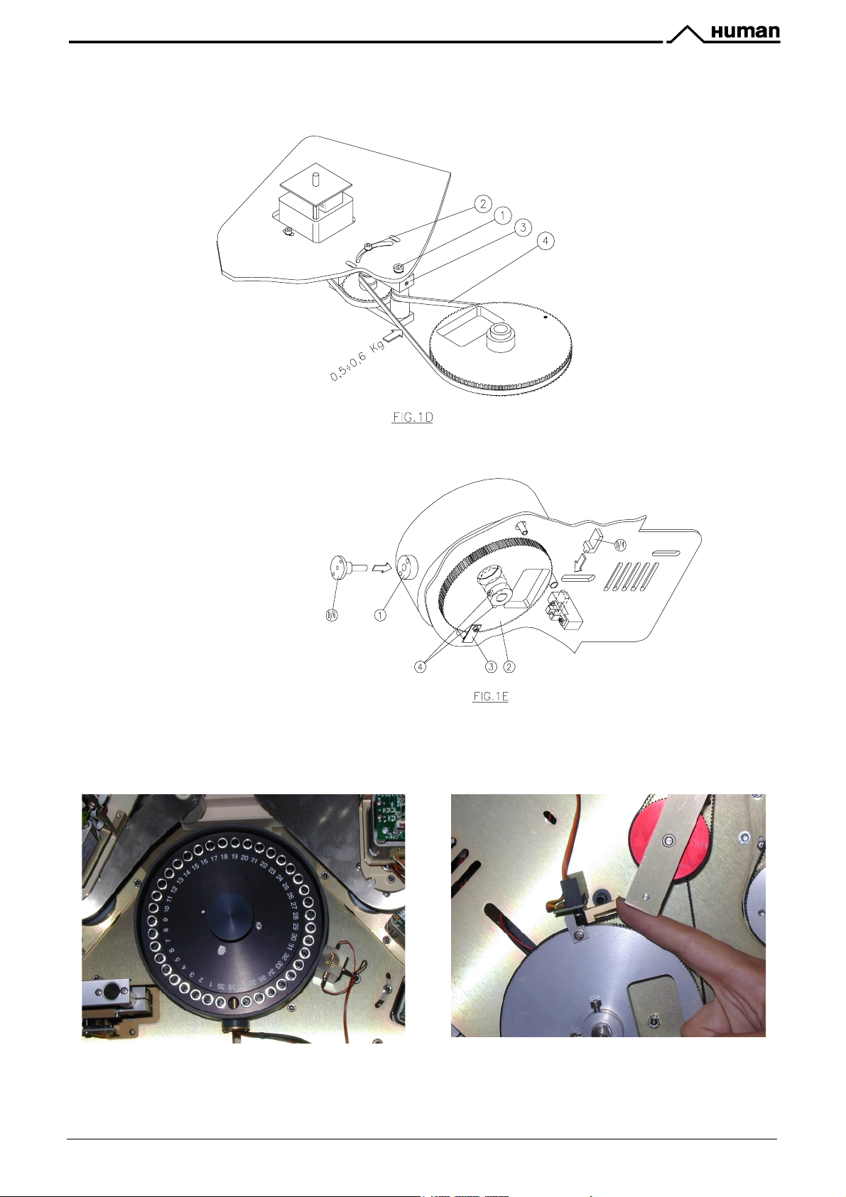
6. Adjust the belt tension: loosen the screw
(2)( hex key 3mm) and the rotating screw (1)
- ( hex key 4 mm), rotate the support (3) (counterclockwise) to obtain a deflection in
the center of the belt of about 5 mm with a
pressure of 0.5 -0.6 kg. ( see 5 in Fig. 1D)
7. Lock the screws (1 and 2).
8. Install the reaction plate into its place in the
incubation chamber, insert the locking pin
and screw in the knob.
9. Insert the reference pin D/6 into the window
seat (1) in Fig.1E and into the hole of cuvette
38.
10. Position the pulley (2) in Fig. 1E until the HOME Flag touches the device D4 in Fig. 1E.
11. Lock the screws (4) of the pulley (2) - (use hex key 3 mm), remove the friction device D/11,
remove the device D6 and re-assemble in sequence: cuvette 38, the window in the incubation
bath, photometer, lamp support and the spring.
Service Manual HumaStar 300 3/27
4/27 Service Manual HumaStar 300
Service Manual HumaStar 300 5/27
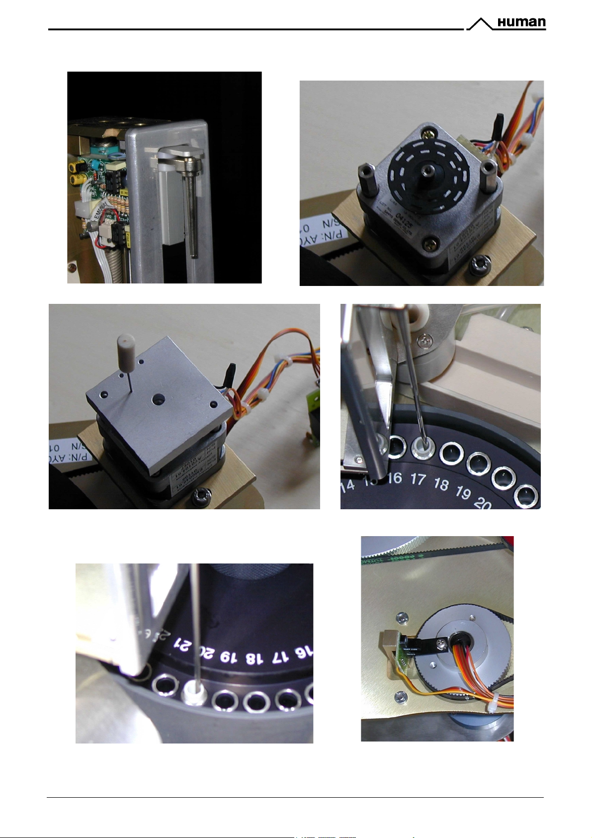
%65M2/1J(6,5
.-,3/862(50.-5-13
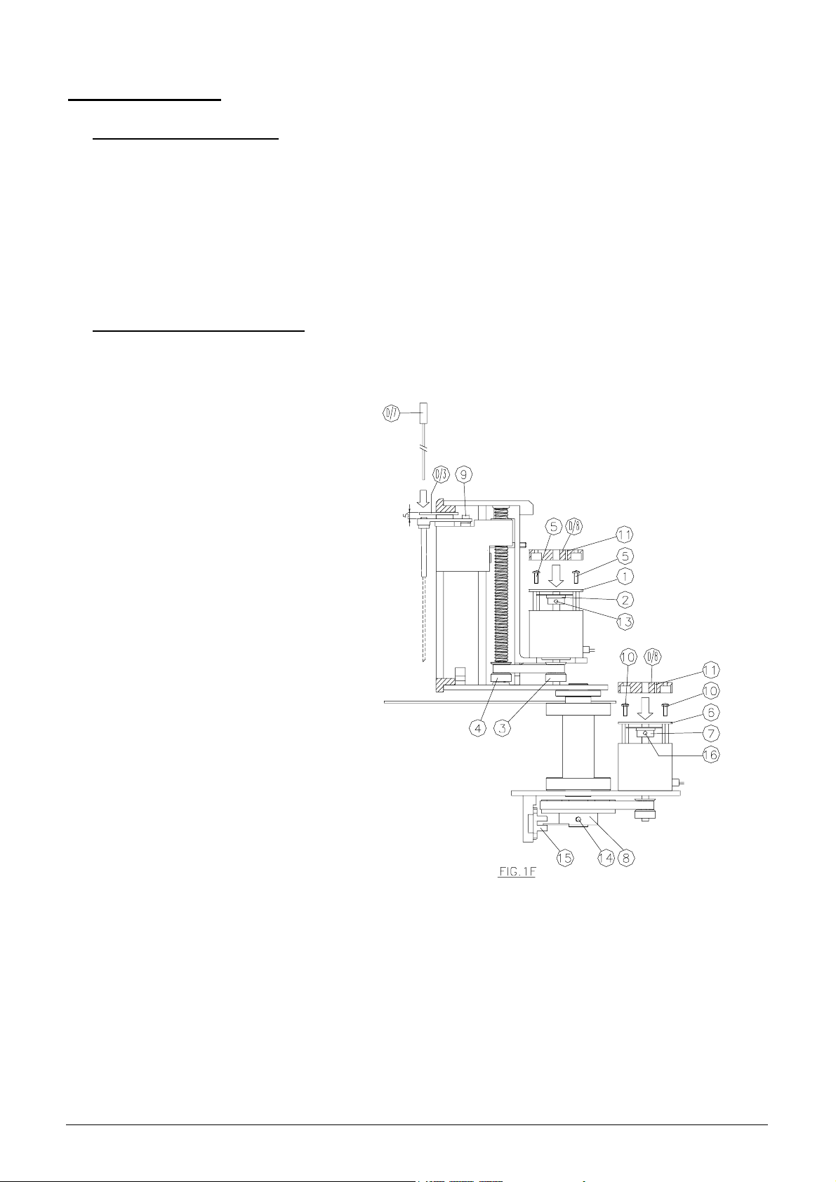
1. Remove the PCB of the encoder (1) in Fig. 1F and replace it with the device D/8 to align the
SYNC. (11) in Fig.1F.
2. Check all the screws of the pulley (3 and 4) in Fig. 1F and make sure that they are all well locked.
( hex key 2 mm)
3. Bring the probe support to 5 mm from the top (12) in Fig. 1F -(use the spacer 2 mm D/3)
4. Rotate the encoder disk (2) until the hole of the SYNC is perfectly aligned with the reference
device; lock the disk screw (13) ( hex key 1.5 mm. Make sure not to tighten too strongly since the
support is made in PVC) Reinsert the PCB of the encoder and lock the screws (5).
,0363/0162(50.-5-13
1. Remove the PCB of the encoder (6) and replace it with the device D/8 to align the SYNC (11) in
Fig. 1F.
2. Insert into cuvette 17 or 20 the
adapter device D/2, loosen the
screws of the pulley (8) in Fig.1F.
3. Position the PROBE (Sample
Reagent) perfectly perpendicular
on the opening of cuvette 17 or
18,
4. Introduce the Probe declogger
D/7 into the probe holder. ("A5"
L=205; "S300" L=178) and rotate
the pulley (8) in Fig.1F to align
the flag HOME to the center of
the OPTO (15) in Fig.1F.- lock the
screws (14) of the pulley (8).
5. Rotate the cam (9) in Fig. 1F (plain screwdriver 2.5 mm) and
verify that the probe rotates inside
the perimeter of the hole of the
adapter.
6. Hold the ARM fixed and rotate the
disk (7) until the hole of the SYNC
(11) is perfectly aligned with the
hole of device D/8 in Fig. 1F.
7. Lock the screws (14) of the disk
(use hex key 1.5mm - Make sure
D<&(&<(B<QE(&>:(?Q':O(&<<(&+A>&B;
since the support is made in PVC)
8. Reinsert the PCB of the encoder
and lock the screws (10).
6/27 Service Manual HumaStar 300
Service Manual HumaStar 300 7/27
 Loading...