

Human HumaStar 300 Service manual
HumaStar 300
|
Service Manual
Cat No. 17901s/2


REVISION LIST OF THE MANUAL
Rev. /DATE. REVISION DESCRIPTION
SYSTEM VERSION
COPYRIGHT
Copyright 2010, Human GmbH, Wiesbaden, Germany. All rights reserved.
No part of this documentation may be reproduced in any form, nor processed, copied or
distributed by means of electronic systems, without prior permission of Human GmbH in
writing. Since all precautionary measures were taken into account in producing these operating
instructions, the manufacturer accepts no responsibility for any errors or omissions. This includes any liability for damage that could arise from possible incorrect operation based on this
information. Subject to changes without notice as result of technical development.
SERVICE UND SUPPORT


Contents
TABLE OF CONTENTS
1 SAFETY INSTRUCTIONS
1.1 INTRODUCTION 1
1.2 USER WARRANTY 1
1.3 INTENDED USE OF THE INSTRUMENT 2
1.4 GENERAL SAFETY WARNINGS 2
1.5 DISPOSAL MANAGEMENT CONCEPT 3
1.6 INSTRUMENT DISINFECTION 3
1.7 BIOHAZARD WARNING 4
2 THE ANALYZER - HUMASTAR 300 7
2.1 GENERAL DESCRIPTION 7
2.2 MAIN CHARACTERISTICS 7
2.3 OPERATION 10
2.4 USER WARRANTY 11
2.5 INSTALLATION 12
2.5.1 Unpacking 12
2.5.2 Installation 13
2.5.3 Environmental Requirements 13
2.5.4 Livel setting of Analyzer 13
2.5.5 Operating-Temperature-Limits 13
2.5.6 Power Requirements 14
2.6 ASSEMBLY PROCEDURE 14
2.6.1 External Connections 14
2.6.2 Connections in the back of the Analyzer 15
2.6.3 Hydraulic Connections 16
2.7 ANALYZER COMPONENTS 17
2.7.1 Monitor 17
2.7.2 TOP View of the analyzer 17
2.7.3 Analytical Plate 17
2.7.4 Reagent Chamber 18
2.7.5 Reagent Arm 19
2.7.6 Sample Tray 19
2.7.7 Sampling Arm 21
2.7.8 Probe Washing Well 22
2.7.9 Sample and Reagent Diluter 22
2.7.10 Peristaltic Washing Pumps 24
2.7.11 Photometer Module 24
1

2.8 SOFTWARE 24
3 OVERALL BLOCK DIAGRAMM (P/N: EI0110.01) 27
3.1 POWER SUPPLY CONNECTIONS (P/N:EI0107.01) 27
3.2 MAIN POWER SUPPLY ASSEMBLY (P/N: AY0097.04) 29
3.2.1 PCB Power Distribution (P/N: 17970/27) 29
3.2.2 Transformer (P/N: EM0050.01) 30
3.2.3 PC Power Supply (P/N: 17956/1) 30
3.2.4 Power Supply + 24V (P/N: 17956/2) 31
3.3 POWER SUPPLY BOARD (P/N: 17970/7) 31
3.4 POWER SUPPLY MAINTENANCE 33
3.4.1 To remove the Power supply 33
3.4.2 Replacement of the PC Power Supply 35
3.4.3 Main Power Switch Replacement 35
3.4.4 Fuse Replacement 36
3.4.5 To replace Transformer 36
3.4.6 Replace Power Supply + 24V 37
3.4.7 Replacement of the Power Distribution Board 37
3.5 TROUBLE SHOOTING GUIDE 37
3.6 SPARE PARTS 41
3.7 ENCLOSED DOCUMENTATION 43
3.7.1 EI0110.01.0.DW (block diagram) 43
3.7.2 EI0107.01.0.DW (block diagram) 43
3.7.3 EI0107.01.0.SC (electrical diagram) 43
3.7.4 17970/27.B.SC (electrical diagram) 43
3.7.5 17970/27.A.PM (assembly drawing) 43
3.7.6 EM0050.01.B.SC (electrical diagram) 43
3.7.7 EA0067.02.0.SC (electrical diagram) 43
3.7.8 17970/7.A.SC (electrical diagram) 43
3.7.9 17970/7.B.PM (assembly drawing) 43
4 INTERFACE PUMP - VALVES (P/N: 17970/24) 55
4.1 MAINTENANCE 57
4.1.1 To Replace Pump Interface and valves 57
4.2 TROUBLE SHOOTING GUIDE 58
4.3 SPARE PART LIST 60
4.4 ENCLOSED DOCUMENTATION 60
4.4.1 17970/24.A.SC (electric diagram pag. 1/3) 60
4.4.2 17970/24.A.SC (electric diagram pag. 2/3) 60
4.4.3 17970/24.A.SC (electric diagram pag. 3/3) 60

Contents
4.4.4 17970/24.A.PM (assembly drawing) 60
5 POWER SUPPLY PHOTOMETER LAMP (P/N: 17970/10) 67
5.1 TROUBLE SHOOTING GUIDE 68
5.2 SPARE PART LIST 68
5.3 ENCLOSED DOCUMENTATION 69
5.3.1 17970/10.A.SC (electrical diagram) 69
5.3.2 17970/10.A.PM (assembly drawing) 69
6 MICROPROCESSOR ASSEMBLY (P/N: EA0073.02) 73
6.1 CPU SLAVE (P/N:17970/8) 74
6.2 MOTHER BOARD (P/N: 17970/9) 82
6.3 MAINTENANCE 85
6.3.1 CPU slave board replacement 85
6.3.2 Mother Board replacement 85
6.4 TROUBLE SHOOTING GUIDE 86
6.5 SPARE PART LIST 89
6.6 ENCLOSED DOCUMENTATION 90
6.6.1 EB0045.00.B.SC (electrical diagram) 90
6.6.2 17970/8.A.PM (assembly drawing) 90
6.6.3 17970/9.A.SC (electrical diagram) 90
6.6.4 17970/9.B.PM (assembly drawing) 90
7 DILUTER DRIVER (P/N: 17970/11) 97
7.1 MAINTENANCE 99
7.1.1 Replacement of Driver Board 99
7.2 TROUBLE SHOOTING GUIDE 100
7.3 SPARE PART LIST 101
7.4 ENCLOSED DOCUMENTATION 101
7.4.1 17970/11.A.SC (electrical diagram) 101
7.4.2 17970/11.C.PM (assembly drawing) 101
8 MOTOR CONTROL ASSEMBLY (P/N:AY0113.01, AY0114.01) 105
8.1 M/B MOTOR CONTROL MOTOR (P/N: 17970/26) 105
8.2 M/B MOTOR CONTROL (P/N: 17970/26) 107
8.3 DRIVER FOR STEPPER MOTOR (P/N:17970/20 - 23) 109
8.4 MAINTENANCE CONTROL MOTOR ASSEMBLY 111
8.4.1 Driver module replacement 111
8.4.2 Replacement of M/B Contorl motor board 111

8.5 TROUBLE SHOOTING GUIDE 112
8.6 SPARE PART LIST 114
8.7 ENCLOSED DOCUMENTATION 115
8.7.1 17970/26.A.SC (electrical diagram) 115
8.7.2 17970/26.A.PM (assembly drawing) 115
8.7.3 17970/26.A.SC (electical diagram) 115
8.7.4 17970/26.A.PM (assembly drawing ) 115
8.7.5 EB0092.01.A.SC (electrical diagram) 115
8.7.6 EB0092.02.A.PM (assembly drawing) 115
8.7.7 EB0092.03.A.PM (assembly drawing) 115
8.7.8 EB0092.04.A.PM (assembly drawing) 115
8.7.9 EB0092.05.A.PM (assembly drawing) 115
8.7.10 EB0092.06.A.PM (assembly drawing)
115
9 DATA PROCESSING OF THE OPTICAL SIGNAL 127
9.1 PREAMPLIFIER (P/N: 18720/8) 127
9.2 CONVERTER A/D (P/N: 17970/19) 128
9.3 PHOTOMETER (P/N:17970/30) 130
9.4 MAINTENANCE 131
9.4.1 Photometer Module 131
9.4.2 Replacement of the preamplifier 131
9.5 TROUBLE SHOOTING GUIDE 132
9.6 SPARE PART LIST 135
9.7 ENCLOSED DOCUMENTATION 135
9.7.1 18720/8.A.SC (electrical diagram) 135
9.7.2 18720/8.A.PM (assembly drawing) 135
9.7.3 17970/19.A.SC (electrical diagram) 135
9.7.4 17970/19.B.PM (assembly drawing) 135
10 PERSISTALTIC PUMP DRIVER (P/N: EB0033.XX) 141
10.1 LINEAR PUMP DRIVER (P/N:EB0122.01) 143
10.2 MAINTENANCE 144
10.2.1 Replacement Peristaltic Pump Driver Board 144
10.2.2 Replacement of the linear pump driver board P6 145
10.3 TROUBLE SHOOTING GUIDE 145
10.4 SPARE PART LIST 147
10.5 ECLOSED DOCUMENTATION 147
10.5.1 8EB0033.01.A.SC (electrical diagram) 147
10.5.2 EB0033.01.A.PM (assembly drawing) 147

Contents
10.5.3 EB0033.02.A.SC (electrical diagram) 147
10.5.4 EB0033.03.A.SC (electrical diagram) 147
10.5.5 EB0033.03.0.PM (assembly drawing) 147
10.5.6 EB0122.01.0.SC (electrical diagram) 147
10.5.7 8EB0122.01.0.PM (electrical drawing) 147
11 ENCODER MOTORE 157
11.1 ENCODER MOTOR + HOME (P/N EB0120.01) 159
11.2 MAINTENANCE 162
11.2.1 Replacement of the Encoder board 162
11.3 TROUBLE SHOOTING GUIDE 163
11.4 SPARE PART LIST 164
11.5 ENCLOSED DOCUMENTATION 165
11.5.1 EB0072.01.A.SC (electrical diagram) 165
11.5.2 EB0072.01.A.PM (assembly drawing) 165
11.5.3 EB0120.00.0.SC (electrical diagram) 165
11.5.4 EB0120.01.0.PM (assembly drawing) 165
12 LIQUID LEVEL SENSOR (P/N:17970/31) 171
12.1 MAINTENANCE 172
12.1.1 Replacement of Level Sensor and its flat cable 172
12.2 TROUBLE SHOOTING GUIDE 173
12.3 SPARE PART LIST 174
12.4 ENCLOSED DOCUMENTATION 174
12.4.1 17970/31.0.SC (electical diagram) 174
12.4.2 17970/31.0.PM (assembly drawings) 174
13 OPTICAL SENSOR (P/N: EB0086.XX, PN: EA0071.01, P/N:
EA0075.01)
13.1 MAINTENANCE 179
13.2 TROUBLE SHOOTING GUIDE 180
13.3 SPARE PART LIST 180
13.4 ENCLOSED DOCUMENTATION 181
13.4.1 EB0086.00.0.SC (electrical diagram) 181
13.4.2 EA0071-75.00.0.SC (electrical diagram) 181
179

14 COMPUTER MODULE (P/N: AY0096.01, P/N: AY0199.01) 185
14.1 COMPUTER PC MASTER (P/N: 17889) 186
14.2 PASSIVE BOARD 6 SLOT ISA BUS (P/N: 17810/7) 187
14.3 MULTI - SERIAL PORT (P/N: 910.002.031) 188
14.3.1 Check and the configuration multi-serial board parameters 188
14.4 CONFIGURATION OF BIOS 190
14.5 TO INSTALL SOFTWARE FROM CD-ROM TO HARD DESK 193
14.5.1 To Save the SW Archives 194
14.5.2 Preparation HW 194
14.5.3 Update SW 194
14.5.4 To Restore HW 195
14.5.5 To Restore SW 195
14.6 MAINTENANCE 195
14.6.1 To Replace the PC MAster Board 195
14.6.2 To Replace the multi-serial Board 196
14.6.3 To Replace the Hard Disk and the Floppy Driver 196
14.6.4 To Replace the passive ISA BUS Board 196
14.7 TROUBLE SHOOTING GUIDE 196
14.8 SPARE PART LIST 199
15 MISCELLANEOUS 201
15.1 DILUTER (P/N: AY0069.05) 201
15.2 AIR PUMP (P/N: AY0121.02) 202
15.3 COOLING SYSTEM (P/N: AY0115.01) 202
15.4 THERMOSTAT (P/N: AY0131.01) 203
15.5 MAINTENANCE 203
15.5.1 Diluter 203
15.5.2 Thermostat 206
15.5.3 Cooling System 208
15.6 TROUBLE SHOOTING GUIDE 212
15.7 SPARE PART LIST 213
15.8 ENCLOSED DOCUMENTATION 214
15.8.1 AY0121.00.0.SC (electrical diagram) 214
15.8.2 M0145.01.0.SC (electrical diagram) 214
15.8.3 AY0115.01.0.SC (electrical diagram) 214
15.8.4 EA0098.01.0.SC (electrical diagram) 214

Contents
16 HYDRAULIC SYSTEM (P/N: HY0012.01) 221
16.1 HYDRAULICS OF THE SAMPLING SYSTEM 221
16.2 HYDRAULICS OF THE INCUBATION BATH 221
16.3 HYDRAULICS OF WASHING AND DRYING THE CUVETTES 222
16.4 WASTE HYDRAULICS 222
16.5 MAINTENANCE 222
16.5.1 General RuLes 222
16.5.2 Peristaltic Pumps 223
16.6 TROUBLE SHOOTING GUIDE 226
16.7 SPARE PART LIST 228
16.8 ENCLOSED DOCUMENTATION 229
16.8.1 HY0012.01.F.CM (Hydraulic diagram page 1 out of 4) 229
16.8.2 HY0012.01.F.CM (Hydraulic diagram page 4 out of 4) 229
16.8.3 HY0012.01.F.CM (Spare part list page 2 out of 4) 229
16.8.4 HY0012.01.F.CM (Spare part Iist page 3 out of 4) 229
17 TEST PROGRAM 235
17.1 DESCRIPTION 235
17.2 DIAGNOSTIC UTILITY 236
17.3 TO RUN DIAGNOSTICS USING THE TESTER.EXE 237
17.3.1 Important Notes and Precautions 237
17.3.2 Utility Reagent System 238
17.3.3 Utility Reaction cuvette - Measuring System 244
17.3.4 Utility of the Sampling System 249
17.4 PRINTMETH.EXE 253
17.5 SATSMITH.EXE 256
17.6 SAVEDBCHEM.EXE 257
17.7 COMMUNICATION PROTOCOL 258
17.7.1 Data Exchange with Host computer 258
17.7.2 Host computer Setup 259
17.7.3 Connections 259
17.7.4 Protocol Structure 259
17.7.5 Transfer of a WorkList (Reception from Host) 260
17.7.6 Transferring Results to Host computer 262
18 MAINTENANCE 267
18.1 PREFACE 267
18.2 OPERATING PROGRAM CHECKS 267
18.2.1 Reagent System 268
18.2.2 Sampling System 269

18.2.3 Reaction and Measurement System Checks 270
18.3 DEVICED FOR MAINTENANCE 272
18.3.1 To remove casing 273
18.4 PHOTOMETER MODULE 275
18.4.1 Photometer 275
18.4.2 To Equalize and Replace Filters 277
18.4.3 Replace Motor and Belt. 280
18.4.4 Replace and clean lenses 281
18.5 TEMPERATURE ADJUSTMENT AND CONTROL 281
18.5.1 Check Temperature in Incubation Bath 281
18.5.2 Check Temperature in the Reagent Chamber 283
18.6 PREPARATION SYSTEM 283
18.6.1 Sampling Arm, vertical movement (Probe) 284
18.6.2 Sampling Arm, rotational movement 286
18.6.3 Reagent Chamber 290
18.6.4 Sample Plate 293
18.7 MEASUREMENT SYSTEM 296
18.7.1 Check Reaction and Measurement Plate 297
18.7.2 Cuvette Washing Arm 303
18.8 PROGRAMMED MAINTENANCE 308
18.8.1 Daily Check 308
18.8.2 Every two weeks 309
18.8.3 Once a month or when necessary 309
18.8.4 Every six months or when necessary 310
18.8.5 Replace Photometer Lamp 310
18.8.6 Programmed Maintenance Table 310

Contents
19 GENERAL TROUBLE SHOOTING GUIDE 313
19.1 PROBLEMS WITH POWER SUPPLY 313
19.2 PROBLEMS WITH MASTER COMPUTER AND ITS CPU SLAVES 313
19.3 PROBLEMS WITH DILUTER 314
19.4 MECHANICAL MOVEMENT PROBLEMS 314
19.5 TEMPERATURE PROBLEMS 315
19.6 PROBLEMS WITH PHOTOMETER, PRE-AMPLIFIER AND LAMP 315
19.7 PROBLEMS WITH UNRELIABLE RESULTS 316
19.8 PREPARATION PROBLEMS 318
19.9 PROBLEMS WITH LEVEL SENSORS AND MIXER 319
19.10 PROBLEMS COOLING SYSTEM 321
19.11 PROBLEMS WITH THERMOSTAT 321
19.12 PROBLEMS WITH PUMPS AND VALVES 322
19.13 LEAKAGE PROBLEMS 322
19.14 PROBLEMS WITH PRINTER 323
19.15 WARNING SIGNALS, ALARMS AND FLAGS 324
20 ACCESSORIES AND SPARE PARTS 327
20.1 ACCESSORIES AND GENERAL SPARE PARTS 327
20.2 ELECTRONIC BOARDS 328
20.3 CABLE KIT MASTER COMPUTER (P/N: KG0058.01) 329
20.4 FUSES 329
20.5 PROGRAMMABLE DEVICES 329
20.6 GENERAL SPARE PARTS 330
20.7 INTERFERENCE FILTERS AND OPTICAL PARTS 330
20.8 COMPLETE MODULES 331
20.9 CONNECTORS AND HYDRAULIC ACCESSORIES 331
20.10 FLAT CABLES IN MOVEMENT 332
20.11 FLAT CABLES FIXED 332
20.12 CALBES UNIPOLAR 332
20.13 MOTORS 333
20.14 ENCORDER ASSEMBLIES 334
20.15 BELTS 334
20.16 SERVICE KIT (P/N:KG0065.01) 334
20.17 BAR CODE READER ASSEMBLY (P/N:AY0133.01) 335
20.18 KIT BAR CODE READER SAMPLES (P/N: KG0055.02) 335
20.19 KIT BAR CODE READER REAGENTS (P/N: KG0055.03) 336
20.20 KIT BAR C. READER REAG-SAMPLE (P/N: KG0056.01) 336
20.21 ISE MODULE (P/N: KG0019.01) 336
20.22 DEVICES FOR MAINTENANCE (P/N: KG0070.01) 337

21 OPTIONAL MODULES 339
21.1 BAR CODE READER 339
21.1.1 Bar Code Reader Interface (P/N: EB0111.01) 340
21.1.2 Assembly Procedure and Maintenance 340
21.1.3 Bar Code Reader Optical Alignment 342
21.1.4 Trouble Shooting Guide 347
21.1.5 Spare Part List 348
21.2 DOCUMENTATION 349
21.3 ISE MODULE (P/N: KG0019.04) 352
21.3.1 Introduction 352
21.3.2 Some Highlights and Specifications 353
21.3.3 ISE Control Board (P/N: EB0181.02) 354
21.3.4 pERISTALTIC PUMP DRIVE (p7n. eb0161:05-06) 357
21.3.5 Serial adapter Board (P/N: EB0171.01) 359
21.3.6 Power Supply for the ISE Module 359
21.3.7 REagents and Solutions needed 359
21.3.8 The ISE Module Parts 360
21.3.9 Mounting and Connecting 361
21.3.10 Operative Procedure 365
21.3.11 Urine determination 366
21.3.12 Maintenance 366
21.3.13 Trouble Shooting Guide 371
21.3.14 Spare Part List 373
21.4 DOCUMENTATION 376

Contents


Contents


safety InstruCtIons 1
1 SAFETY INSTRUCTIONS
1.1 Introduction
This manual is considered as a part of the instrument; it has to be at the
operator’s hand as well as at the maintenance operator’s availability. For
accurate installation, use and maintenance, please read the following
instructions carefully. In order to avoid instrument damage or personal
injury, carefully read the ”GENERAL SAFETY WARNINGS”, describing the suitable
operating procedures. In case of breakdowns or any troubles with the instrument, apply to the local Technical Service.
1.2 User Warranty
HUMAN warrants that instruments sold by one of its authorised
representatives shall be free of any defect in material or workmanship, provided
that this warranty shall apply only to defects which become apparent within
one year from the date of delivery of the new instrument to the purchaser.
The HUMAN representative shall replace or repair any defective item at no
charge, except for transportation expenses to the point of repair.
This warranty excludes the HUMAN representative from liability to replace
any item considered as expendable in the course of normal usage, e.g.: lamps,
valves, syringes, glassware, fuses, diskettes, tubing etc.
The HUMAN representative shall be relieved of any liability under this warranty
if the product is not used in accordance with the manufacturer‘s instructions,
altered in any way not specified by HUMAN, not regularly maintained, used with
equipment not approved by HUMAN or used for purposes for which it was not
designed.
HUMAN shall be relieved of any obligation under this warranty, unless a
completed installation / warranty registration form is received by HUMAN
within 15 days of installation of this product.
This warranty does not apply to damages incurred in shipment of goods. Any
damage so incurred shall be reported to the freight carrier for settlement or
claim.

2
1.3 Intended Use of the Instrument
[IVD]
The instrument is intended for in vitro diagnostic application by
professional users. It has to be used for the expected purposes and in perfect
technical conditions, by qualified personnel, in working conditions and
maintenance operations as described in this manual, according to the GENERAL
SAFETY WARNINGS. This manual contains instructions for professional qualified
operators.
1.4 General Safety Warnings
Use only chemical reagents and accessories specified and supplied by
HUMAN and/or mentioned in this manual. Place the product so that it has proper
ventilation.
The instrument should be installed on a stationary flat working surface, free
from vibrations.
Do not operate in area with excessive dust.
Work at room temperature and humidity, according to the specifications listed
in this manual.
Do not operate this instrument with covers and panels removed.
Only use the power cord specified for this product, with the grounding
conductor of the power cord connected to earth ground.
Use only the fuse type and rating specified by the manufacturer for this
instrument, use of fuses with improper ratings may pose electrical and fire
hazards.
To avoid fire or shock hazard, observe all ratings and markings on the
instrument.
Do not power the instrument in potentially explosive environment or at risk of
fire.
Prior to cleaning and/or maintaining the instrument, switch off the instrument
and remove the power cord.
For cleaning use only materials specified in this manual, otherwise parts may
become damaged. It is recommended always to wear protective apparel and
eye protection while using this instrument. Respective warning symbols, if
appearing in this manual, should be carefully considered.
Gerätename | User manual

safety InstruCtIons 3
1.5 Disposal Management Concept
The currently valid local regulations governing disposal must be observed. It is in
the responsibility of the user to arrange proper disposal of the individual
components.
All parts which may comprise potentially infectious materials have to be
disinfected by suitable validated procedures (autoclaving, chemical treatment)
prior to disposal. Applicable local regulations for disposal have to be carefully
observed.
The instruments and electronic accessories (without batteries, power packs etc.)
must be disposed off according to the regulations for the disposal of electronic
components.
Batteries, power packs and similar power source have to be dismounted from
electric/electronic parts and disposed off in accordance with applicable local regulations.
1.6 Instrument Disinfection
Analytical instruments for in vitro diagnostic involve the handling of human
samples and controls which should be considered at least potentially infectious. Therefore every part and accessory of the respective instrument which
may have come into contact with such samples must equally be considered as
potentially infectious.
Before doing any servicing on the instrument it is very important to
thoroughly disinfect all possibly contaminated parts. Before the instrument is
removed from the laboratory for disposal or servicing, it must be decontaminated.
Decontamination should be performed by authorised well-trained personnel
only, observing all necessary safety precautions. Instruments to be returned
have to be accompanied by a decontamination certificate completed by the
responsible laboratory manager.
If a decontamination certificate is not supplied, the returning
laboratory will be responsible for charges resulting from nonacceptance of the instrument by the servicing centre, or from authority’s
interventions.

4
1.7 Biohazard warning
Analytical instruments for in vitro diagnostic application involve the handling
of human samples and controls which should be considered at least potentially
infectious. Therefore every part and accessory of the respective
instrument which may have come into contact with such samples must equally be
considered as potentially infectious.
For safety reasons, we have labeled instruments with the
„BIOHAZARD“ warning label below.
FIGURE 1
Biological Hazard
Symbol
Gerätename | User manual

safety InstruCtIons 5
Notes:

6
Gerätename | User manual
the analyzer - humastar 300 7
2 THE ANALYZER - HUMASTAR 300
2.1 General Description
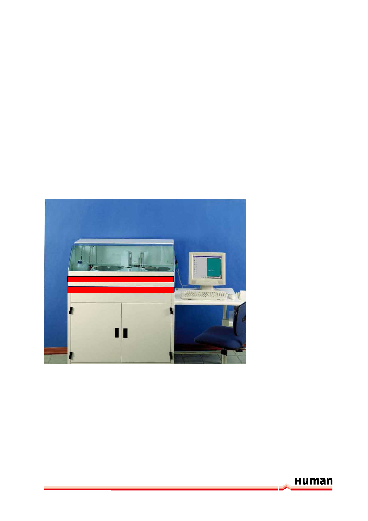
HUMASTAR 300 – is an automatic Random Access Clinical Chemistry Analyzer.
HUMASTAR 300 – with its sophisticated updated software offers great versatility and speed of operation. Its unique characteristics and user friendliness make
this analyzer the top in its class with its productivity and throughput of 300
Clinical Chemistry tests plus 180 ISE tests per hour.
FIGURE 2
2.2 Main Characteristics
HUMASTAR 300 is an automatic Random Access Clinical Chemistry analyzer
fully controlled by a MASTER computer (industrial Pentium) and three CPU
slaves. Smart operation, where all the required test for Patient #1 are processed
before starting on Patient #2, with an immediate print-out of the Patient report.
Speed: 300 test/h independently of method used, including 180 electrolytes
with the built-in ISE module.

8
SAMPLE CAPACITY: 40 PRIMARY TUBES or small plastic sample cups; including
16 places reserved for Standards and Controls, plus 4 places for STATS. Possibility to add samples continuously during operation, up to 240 Patients with up
to 30 different chemistries can be processed at a time.
REAGENT CAPACITY: 30 On-line reagents. Both 50 ml reagent bottles and 8 ml
reagent tubes are placed in the Reagent plate. Each reagent container can be
individually cooled or left at room temperature.
REAGENT VOLUME: Is automatically monitored with an On-line inventory The
number of tests available in each reagent container is displayed on the monitor..
OPEN SYSTEM: an unlimited number of user programmable Chemistry and Immunoassay methods can be programmed.
AUTOMATIC PRE-DILUTION OF SAMPLES: upon request, with 15 different dilution ratios.
BAR CODE READER built-in to identify the samples and /or reagents. (optional).
WALK-AWAY OPERATION: once patients are programmed, all operations are
fully automatic. The reaction cuvettes are automatically washed and dried to
assure a non-stop operation.
INCUBATION takes place in quartz cuvettes immersed in a liquid bath at 37°C to
assure perfect temperature control of the reactions at all times.
DIRECT READING: a built-in multi-filter photometer measures the samples directly in their cuvettes, several times during incubation at 8 different wavelength. Each sample has its own reagent-cuvette blank measured before the
addition of sample.
I.S.E MODULE: (optional) built-in for the simultaneous determination of Sodium,
Potassium and Chloride.
AUTOMATIC REPETITION OF TESTS – results that are critical, outside of linear
range or due to substrate depletion are automatically pre-diluted and repeated.
REAGENT VOLUME: 300 µl of reagent is sufficient to run any test.
Gerätename | User manual

the analyzer - humastar 300 9
LIQUID LEVEL SENSOR: both the reagent and Sampling Probes have built-in
liquid sensors and mixer to assure a correct sample preparation.
KEYBOARD: a full keyboard for easy programming of patients with demographics, including a mouse for easy operation and navigation inside the software.
SOFTWARE: user friendly software with graphic presentation guides the operator step by step through all operations.
HELP ON-LINE: special program to assist the operator at all times during programming and operation.
ON-LINE QUALITY CONTROL: Program checks the precision during standardization and daily operation. Controls are displayed over a period of 60 days, including graph, Mean value, S.D. and %CV.
STATS: an INTELLIGENT STOP enables to introduce a STAT sample at any time
and report its result within only 12 minutes, without interfering with the normal routine operation.
PATIENT REPORTS: are user personalized on a 80 column printer. All result data
is automatically memorized on the built-in hard disk and available for future
consultation.
PRINT ON LINE: if activated it will print results immediately after their final measurement.
GRAPHIC DISPAY: possibility to view the curve of any test for each individual
patient as well as all calibration and Quality control curves.
TEST COUNTER: displays the number and the type of test performed on the analyzer.
MANUAL INPUT OF RESULTS – for tests performed manually or on other instruments to be presented on the final Patient Report.
ARCHIVE ERRORS: a list of errors and warnings of the last 90 days are displayed.
COMMUNICATION: in real time with HOST computer according to ASTM proto-
cols.

10
BI-DIRECTIONAL INTERFACE: via a built-in serial port RS 232/C connection to EDP
systems.
2.3 Operation
The analyzer is a self sufficient system that uses some peripherals, such as Mo-
nitor, Mouse, keyboard and printer.
The analyzer consists in three parts:
- Reagent Plate Chamber: plate containing 30 On-line reagents with a choice to
cool or leave the reagents at room temperature.
- Sample Plate: consisting of 4 segments each holding 10 primary
tubes and 10 small plastic cups for automatic pre-dilution. The center of the plate is reserved for 4 STATS,
and 16 places for Standards and controls.
- Analytical System: consists of a reaction plate with 39 quartz cuvettes,
sitting in a liquid bath at 37°C. A built-in multi-filter
photometer measures the mAbs of the samples directly in the cuvettes. A built-in Wash system automatically washes and dries the cuvettes after use for
a continuous operation.
A reagent probe (with a built-in liquid level sensor) aspirates the reagent and
transfers it into the quartz reaction cuvette. The Reagent is incubated in the
liquid bath at 37°C for 90 sec. During its incubation time, it is measured (this
becomes the reagent/cuvette BLANK for each test).
The Sampling Probe (with its built-in liquid level sensor and mixer) aspirates and
deposits the sample by mixing i into the warm reagent to start the reaction.
Both Sampling and the Reagent arms are automatically washed both internally
and externally, dried and are ready to prepare the next sample.
The 12 seconds operational cycle consists in:
- A) Reagent aspiration, dispensing and measurement Reagent/Cuvette
BLANK
- B) Sample aspiration, dispensing, mixing, a sample measurement
- C) A final sample measurement and calculation
- D) Wash and dry cuvette
- E) Measurement of 20 samples in each cycle. (Each sample is measured every
24 sec – 2 working cycles)
Gerätename | User manual

the analyzer - humastar 300 11
The operation is Patient Oriented. All tests for Patient ONE are prepared before
starting on patient TWO. A full patient report is printed as soon as all the result
data for a given patient are available.
All patient data as well as the analyzer calibrations and their graph are stored
on a hard disk. A built-in user friendly Help and Maintenance programs are a
perfect guide for the operator.
2.4 User Warranty
HUMAN warrants that instruments sold by it or by one of its authorized dealers
shall be free of any defect in material or workmanship, provided that this warranty shall apply only to defects which become apparent within one year from
the date of delivery of the new instrument to the purchaser.
HUMAN shall replace or repair any defective item in its factory in Rome at no
charge, except transportation changes. Instruments for repair have to be sent
to HUMAN with all transportation charges prepaid.
This warranty excludes HUMAN from liability to replace any item considered as
expendable in the course of normal usage, e.g.: lamps, valves, syringes, fuses,
diskettes, monitor, tubing etc.
HUMAN shall be relieved of any liability under this warranty if the product is
not used in accordance with the manufacturer‘s instructions, not regularly
maintained, used with equipment not approved by HUMAN or used for purposes for which it was not designed.
HUMAN shall be relieved of any obligation under this warranty, unless:
1. A completed installation /warranty registration form is received by HUMAN
within 15 days of installation of this product.
2. The Buyer, within the applicable period of time, returns the defective product
or part thereof, freight pre-paid at Buyer‘s expense, to HUMAN.
This warranty does not apply to damages incurred in shipment of goods. Any da-
mage so incurred shall be reported to the freight carrier for settlement or claim.
HUMAN reserves the right to reject any warranty claim on any item that has
been altered or has been returned by non-acceptable means of transportation
or packaging. In all cases, HUMAN has the sole responsibility for determining
the causes and nature of the failure, Crony’s determination with regard thereto
shall be final.

12
Notice: Once the carrier
has taken possession of
the system for transportati-
on from the factory, carrier
assumes all liability until
delivery. All claims for
damage due to transportati-
on must be filed with the
carrier as soon as possible.
2.5 Installation
2.5.1 UNPACKING
Shipping and packing materials have been selected to provide maximum protection during transportation under normal handling conditions.
FIGURE 3
Shipping crate
The system
serial number
is identified as the
serial number of
the Analyzer.
Examine the shipping cartons for indications of damage, e.g. crushed or indented walls, holes or gouges, water damage, etc. Have the carrier note any such
damage on the delivery receipt; this will simplify formulating a claim if any of
the instruments or parts are damaged.
Open the carton from the top and remove the instrument with care. As shown
on the graph above. It is recommended that two people help with the removal
of the instrument from its carton and plastic bag. Save all cartons and packing
material until you are sure you have received everything and all is in good working condition.
Gerätename | User manual
 Loading...