

Human Humastar 180 Service manual
HumaStar 180
|
Service Manual
Cat No. 16900/200


REVISION LIST OF THE MANUAL
Rev. /DATE. REVISION DESCRIPTION
01/2004-07 First edition
02/2005-07 Addition of Chapter 8
03/2010-11 Adaption to new Corporate Design
04/2011-01 Addition of Chapter 5
SYSTEM VERSION
COPYRIGHT
Copyright 2010, Human GmbH, Wiesbaden, Germany. All rights reserved.
No part of this documentation may be reproduced in any form, nor processed, copied or distributed by means of electronic systems, without prior permission of Human GmbH in writing. Since all
precautionary measures were taken into account in producing these operating instructions, the
manufacturer accepts no responsibility for any errors or omissions. This includes any liability for
damage that could arise from possible incorrect operation based on this information. Subject to
changes without notice as result of technical development.
SERVICE UND SUPPORT


CONTENTS
TABLE OF CONTENTS
1 SAFETY INSTRUCTIONS
1.1 INTRODUCTION 5
1.2 USER WARRANTY 5
1.3 INTENDED USE OF THE INSTRUMENT 5
1.4 GENERAL SAFETY WARNINGS 6
1.5 DISPOSAL MANAGEMENT CONCEPT 6
1.6 BIOHAZARD WARNING 7
1.7 INSTRUMENT DISINFECTION 7
2 SYSTEM INTRODUCTION 11
2.1 INTRODUCTION 11
2.2 CHARACTERISTICS 11
2.3 SPECIFICATIONS 12
2.4 FUNCTIONAL DESCRIPTION 13
2.4.1 Process Management 13
2.4.2 Liquid Handling 14
2.4.3 Carousels, Temperature Control and Cooling 17
2.4.4 Measurement System 20
3 ELECTRONICS 23
3.1 INTRODUCTION 23
3.2 SCHEMATIC DIAGRAM OF ELECTRONICS 23
5
4 SERVICE SOFTWARE “EULY SERVICE” 25
4.1 INTRODUCTION 25
4.2 INSTALLATION OF EULY SERVICE 25
4.3 SERIAL SETTINGS 25
4.4 SCRIPT 25
4.4.1 Example for a reading through Euly Service Script 31
4.5 REAGENTROTOR 31
4.6 CUVETTEROTOR 31
4.7 BELT 31
4.8 PIPETTOR 32
4.9 EULYTEST 32
4.10 ENDURANCE TEST 32
4.11 DEVICE DATA 32
4.12 FW UPDATE 32
4.13 PHOTO 32

4.14 PUMPS-VALVES 32
4.15 INFO 32
5 MAINTENANCE 33
5.1 INTRODUCTION 33
5.2 SYRINGES 33
5.3 SYRINGE VALVES 33
5.4 TUBINGS 33
5.5 PHOTOMETER 34
5.6 X-DRIVE 34
5.7 Z-DRIVES 34
5.8 LIQUID DETECTION 35
5.9 MAGNETIC VALVES 35
5.10 PROBES 35
5.11 MEMBRANE PUMPS 35
6 TESTS/TROUBLESHOOTING 37
6.1 INTRODUCTION 37
6.2 FUNCTIONAL TESTS 37
6.3 TROUBLESHOOTING 39
6.3.1 Reagent Rotor 39
6.3.2 Cuvette Rotor 40
6.3.3 Belt 42
6.3.4 Pipettor 44
6.3.5 Liquid Detection 45
6.3.6 Liquid Flood 47
6.3.7 Communication 48
7 REPLACEMENT 49
7.1 INTRODUCTION 49
7.2 CAROUSEL UNIT WITH NEW REAGENTROTORSENSOR 49
7.3 CAROUSEL UNIT WITH OLD REAGENTROTORSENSOR
(POTENTIOMETER)
7.4 CENTERING MAGNET 59
7.5 COVER 64
7.6 CUVETTE DRIVE MOTOR ASSEMBLY 67
7.7 CUVETTE ROTOR BOARD 71
7.8 MASTER BOARD 72
7.9 PHOTOMETER 74
7.10 PIPETTOR ARM 76
54

CONTENTS
7.11 PROBES 80
7.12 REAGENT ROTOR CONTROL BOARD 82
7.13 REAGENT ROTOR POTENTIOMETER 83
7.14 SYRINGE PUMPS 89
7.15 WASHING PUMPS 92
8 ADDITIONAL INFORMATIONS 95
8.1 INTRODUCTION 95
8.2 PIPETTOR ARM 95


SAFETY INSTRUCTIONS 5
1 SAFETY INSTRUCTIONS
1.1 Introduction
This manual is considered part of the instrument and must be available to the
operator and the maintenance personnel. For accurate installation, use and
maintenance, please read the following instructions carefully.
In order to avoid damage to the instrument or personal injury, carefully read
the ”GENERAL SAFETY WARNINGS”, describing the appropriate operating procedures. Please contact your HUMAN authorised local Technical Service in the
event of instrument failure or other difficulties with the instrument.
1.2 User Warranty
HUMAN warrants that instruments sold by one of its authorised
representatives shall be free of any defect in material or workmanship, provided
that this warranty shall apply only to defects which become apparent within
one year from the date of delivery of the new instrument to the purchaser.
The HUMAN representative shall replace or repair any defective item within this
warranty period at no charge, except for transportation expenses to the point
of repair.
This warranty excludes the HUMAN representative from liability to replace
any item considered as expendable in the course of normal usage, e.g.: lamps,
valves, syringes, glassware, fuses, tubing etc.
The HUMAN representative shall be relieved of any liability under this warranty
if the product is not used in accordance with the manufacturer‘s instructions,
altered in any way not specified by HUMAN, not regularly maintained, used with
equipment not approved by HUMAN or used for purposes for which it was not
designed.
1.3 Intended Use of the Instrument
The instrument must be used for its intended purpose (see paragraph 2). It must
be operated in perfect technical conditions, by qualified personnel, in such
working conditions and maintained as described in this manual, in the GENERAL
SAFETY WARNINGS. This manual contains instructions for qualified professional
operators.
[IVD]

6
1.4 General Safety Warnings
Use only chemical reagents and accessories specified and supplied by
HUMAN and/or mentioned in this manual. Place the product so that it has
proper ventilation.
The instrument should be installed on a flat, stationary working surface, that is
free of vibrations.
Do not operate in area with excessive dust.
Operate at temperature and at a humidity level in accordance with the
specifications listed in this manual.
Do not operate this instrument with covers and panels removed.
Use only the power cord specified for this product, with the grounding
conductor of the power cord connected to earth ground.
Use only the fuse type and rating specified by the manufacturer for this
instrument.
The use of fuses with improper ratings may pose electrical and fire
hazards.
To avoid fire or shock hazard, observe all ratings and markings on the
instrument.
Do not power the instrument in environments that are potentially explosive or
at risk of fire.
Prior to cleaning and/or performing maintenance on the instrument, switch off
the instrument and remove the power cord.
Only cleaning materials described in this manual may be used, as other materials may damage parts. It is recommended to always wear protective clothing
and eye protection while using this instrument.
All warning symbols that appear in this manual must be carefully observed.
HumaStar 180 | Service manual
1.5 Disposal Management Concept
The applicable local regulations governing disposal must be observed. It
is the user‘s responsibility to arrange for proper disposal of the individual
components.
All parts which may contain potentially infectious materials must be
disinfected by suitable, validated procedures (autoclaving, chemical treatment)
prior to disposal. Applicable local regulations for disposal must be carefully
observed. The instruments and electronic accessories (without batteries, power
packs etc.) must be disposed of according to the applicable local regulations
for the disposal of electronic components.
SAFETY INSTRUCTIONS 7
Batteries, power packs and similar power sources must be removed from
electric/electronic parts and disposed of in accordance with applicable local
regulations.
1.6 Biohazard Warning
Analytical instruments for in vitro diagnostic application involve the handling
of human samples and controls which should be considered at least potentially
infectious. Therefore every part and accessory of the respective
instrument which may have come into contact with such samples must equally
be considered as potentially infectious.
The „BIOHAZARD“ warning label must be affixed to the instrument prior to first
use with biological material!
FIGURE 1
Biological Hazard
Symbol
1.7 Instrument Disinfection
Before performing any servicing on the instrument it is very important to
thoroughly disinfect all possibly contaminated parts. Before the instrument is
removed from the laboratory for disposal or servicing, it must be
decontaminated. Decontamination must be performed by authorised welltrained personnel, and in observance of all necessary safety precautions.

8
HumaStar 180 | Service manual

SAFETY INSTRUCTIONS 9
Notes:

10
HumaStar 180 | Service manual

SYSTEM INTRODUCTION 11
2 SYSTEM INTRODUCTION
- Characteristics, Specifications & Performance
- Functional Description
2.1 Introduction
HumaStar 180 is a fully automated, random access Clinical Chemistry Analyser
for wet chemistry applications. It has an open structure, so that reagents from
most manufacturers can be used on the system.
HumaStar 180 is computer controlled and uses the Software Package „DETect“
for data reduction and result evaluation.
HumaStar 180 has been developed in a way as to maximise throughput at
maximum comfort, and at the same time to minimise maintenance efforts to be
taken by the user.
HumaStar 180 is fitted with a patented, maintenance free measuring street,
featuring 20 photometer channels for individual wavelength selection and
maximum flexibility.
2.2 Characteristics
Access Modes: - Random Access
- Stat (immediate access and execution)
Processing Modes: - Patient by Patient
- Test by Test
Analysis Modes: - Endpoint (Substrates)
- Kinetic (Enzymes)
- Initial Rate (fixed time kinetics)
- Serum Blank (differential)
- Turbidimetric (immunoturbidimetry)
- Multi Standard (quantitative)
- Bichromatic
- Multi Chemistry
- Intermethodes Calculation (mathematical)

12
2.3 Specifications
TABLE 1
Throughput: - around 150 Tests/hr under speed – optimised
conditions
Carousel: - 25 reagent positions (with SW update up too
50 positions)
- 25 sample positions (random access)
- 25 serum cup positions (minimum 300μl
volume)
- 300 test positions (75x4 cuvettes)
- Customized carousels available !
Liquid Handling: - 2 independent Syringes:
Sample: 1 - 200μl in 1μl steps
Reagent: 1 - 900μl in 1μl steps
- CV less 2,0% for Volumes > 10μl
- High pressure washing
- Autocleaning
- Backflush function
- Easy maintenance
Measurement System: - Maintenance Free !
- Light sources: LED
- Detectors: Photodiodes
- Temperature controlled
- 5 inbuilt photometers, 4 channels each
- 20 independent channels
- up to 20 different wavelegths at a time
- Wavelength range: 340 – 900 nm
- Standard filters:
- 340, 405, 505, 546 & 620nm (4 each)
- Resolution: 0,0001 ABS
- Accuracy: <1% CV at 1ABS / 405nm
- Linearity: 0.0000 – 3.0000 OD better than +/- 1%
- Drift: less than 0.001 OD / hr
Temperature Control: - Reagent cooling (ambient minus 10°C)
- (water circulation w/ external cooler)
- Cuvette heating (electrical) in carousel and
- reading path: 37°C
- Liquid heating (electrical) in probes
HumaStar 180 | Service manual

SYSTEM INTRODUCTION 13
Power Requirements: - 85-264V, 50/60 Hz (autodetecting)
- Power Consumption: max 150 VA
- Mains Fuse: 2 x 2A T (slow blow)
Measures: - Dimensions: 810 x 550 x 550 (w x d x h)
- Weight: 28kg
Environmental: - Operation: 18 - 35°C, 10 - 90% rel. Hum.
- Storage: -40°C – 70°C, 5 – 95% rel. Hum.
Options: - External ISE module f. electrolytes
- Handheld Barcode Reader f. pos. Sample ID
Disposables: - Cuvette block for 4 tests each
(typical reading volume 200μl)
- Reagent bottles
- Serum Cups (1,5ml-minimum volume 300μl)
Overvoltage Cat.: II
Pollution Degree: 2
Method of Disposal: - Contaminated Waste
Usage: - Commercial
2.4 Functional Description
The Clinical Chemistry Analyser “HumaStar 180” comprises the following main
functional units:
- Process Management
- Liquid Handling
- Carousels
- Temperature control
- Cooling (optional)
- Measurement System
- DETect Software package
The following explains the functions of all these units, as well as their
interference within eachother.
2.4.1 PROCESS MANAGEMENT
The working principal of HumaStar 180 is based on a
modular system, which is controlled by a PC via the Process Manager (inbuilt in
HumaStar 180).
14
Each module is fitted with it’s own “intelligence” and functions as a slave to the Process
Manager. The process manager is connected to a PC via RS 232 and receives his orders from DETect
Software package running on the PC. When a process is started on DETect (e.g.: testing a sample
for certain paramters), DETect cuts the complete process into the required steps:
- Washing the probes
- Pipetting the reagent(s)
- Pipetting the sample
- Mixing
- Incubating
- Reading
These process steps are sent to the process manager in the instrument, one at a time, exactly
whenappropriate. The process manager himself distributes the necessary commands to the
modules. The modules “fulfill the order” and report back to the process manager, which himself
provides DETect with the actual status accordingly.
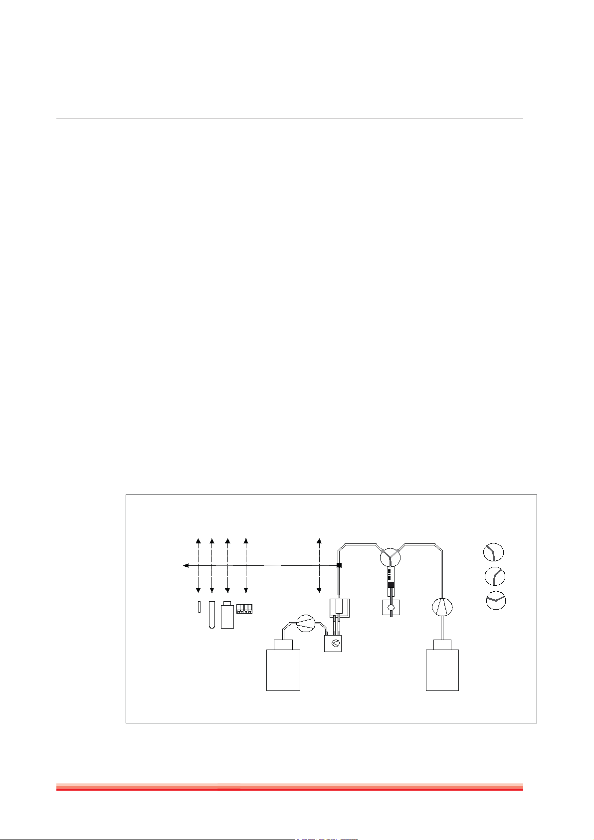
FIGURE 2
Liquid Path
2.4.2 LIQUID HANDLING
The functional unit “Liquid Handling” consists of two independent Liquid paths, one for Sample
pipetting and one for Reagent pipetting. All involved electrical components such as drive motors,
valves and syringes are connected to and controlled by the central Process Manager.
X Mo ve men t
10
Z Movement
3
4
5
13
6
11
7
8
9
Valve Positions:
2
VP a
VP b
VP c
12
Waste
14
System
Liquid
1
HumaStar 180 | Service manual

SYSTEM INTRODUCTION 15
Explanation:
1 System Liquid Bottle 6 Probe w. liquid detection 11 Wash Station
2 Membrane Pump 7 Cuvette 12 Splitting Valve
3 Syringe 3-way Valve 8 Reagent Container 13 Waste Membrane Pump
4 Syringe Pump & Syringe 9 Primary Sample Tube 14 Waste Bottle
5 Syringe Pump Drive 10 Serum Cups
Both liquid paths are built up identical, with the only difference of the size of the
syringes and the probes:
Syringe: 1ml for Reagent path
250 μl for Sample path
X- and Z – movement are realised by the pipetting arm, which holds the
probes and the probes drives, together with all necessary motors, sensors and
electronics.
2.4.2.1 Pipetting cycle
The system is able to pippete reagents in either single- or multi pipetting mode.
Multipipetting mode means that, a multiple of the required reagent volume per
test of one reagent will be aspirated and then be distributed into the different
target containers (cuvettes) accordingly.
A complete pipetting cycle incorporates the following steps:
Single Pipetting (Sample or Reagent)
Wash probe
- move probe in Z direction into wash station
- flush with System liquid for a pre-defined time span
- lift probe in Z direction to top position
Probe: 0.5 mm inner diameter for Reagent path
0.4 mm inner diameter for Sample path
Pick up source liquid
- move probe in X direction to source container (reagent container, sample
tube or serum cup)
- move probe in Z direction into source container until liquid is detected
- aspirate the required test volume (driven by syringe pumps)
- lift probe in Z direction to top position

16
REAGENT Pipetting:
Pipette liquid into target container
- move probe in X direction to target container (Cuvette)
- move probe in Z direction into target container
- pipet required test volume into target container
- lift probe in Z direction to top position
SAMPLE Pipetting:
Pipette liquid into target container
- move probe in X direction to target container (Cuvette)
- move probe in Z direction into target container until liquid is detected
- pipet required test volume into target container
- mix by aspirating and re-pipetting
- lift probe in Z direction to top position
Move probe in X direction to home (Washstation)
Multi Pipetting (Reagent only)
Wash probe
- move probe in Z direction into wash station
- flush with System liquid for a pre-defined time span
- lift probe in Z direction to top position
Pick up source liquid
- move probe in X direction to source container (reagent container)
- Move probe in Z direction into source container until liquid is detected
- aspirate a multiple of the required test volume (driven by syringe pumps)
- lift probe in Z direction to top position
Pipet liquid into target container
- move probe in X direction to target container 1 (Cuvette)
- move probe in Z direction into target container 1
- pipet required test volume into target container 1
- lift probe in Z direction to top position
- move probe in X direction to target container 2 (Cuvette)
- Move probe in Z direction into target container 2
- pipet required volume into target container 2
- lift probe in Z direction to top position
- repeat for target containers 3 - n
Move probe to home (Washstation)
HumaStar 180 | Service manual
SYSTEM INTRODUCTION 17
2.4.3 CAROUSELS, TEMPERATURE CONTROL AND COOLING
HumaStar 180 is using two Carousels, the Inner and the Outer Carousel. Both
carousels are directly connected to and controlled by the central Process
Manager.
- The INNER Carousel for carrying Samples, Reagents, Standards,
Calibrators and Controls. The inner carousel can optionally be cooled. This
option comprises an external cooling unit and cooled liquid is circulated
underneath the inner carousel.
- The OUTER Carousel for carrying the disposable Cuvettes. The outer carousel
is temperature controlled to 37° C (standard).
FIGURE 3
Carousels, loaded, inside
Instrument
Inner
Outer
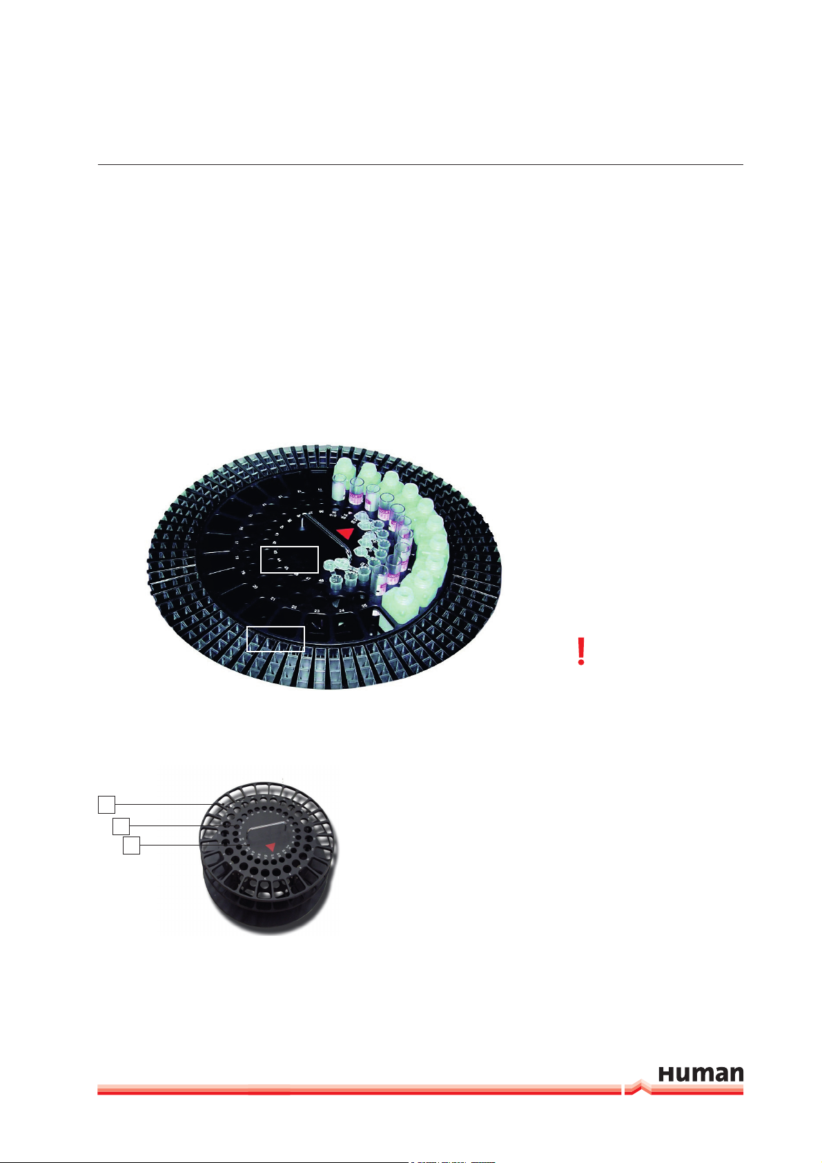
2.4.3.1 Inner Carousel
The inner carousel can easily be removed for loading.
*2 Controls, marked as C1 and C2
1
2
3
10 Standards / Calibrators marked
as S1, S2 ... S10 (if less or no Std/
Cal are used, these positions can
be used for additional Samples)
13 free positions marked as 26,
27 ....... 48
Please refer to Chapter 2 for
instructions on how to re-
move, load and replace the inner
carousel.
FIGURE 4
Inner Carousel
The Inner Carousel features:
1 25 Positions for Reagents,
marked as 1, 2 ... 25
2 25 Positions for Primary
Sample Tubes, marked as
1, 2 ... 25
3 25 Positions for Serum
Cups for:*
18
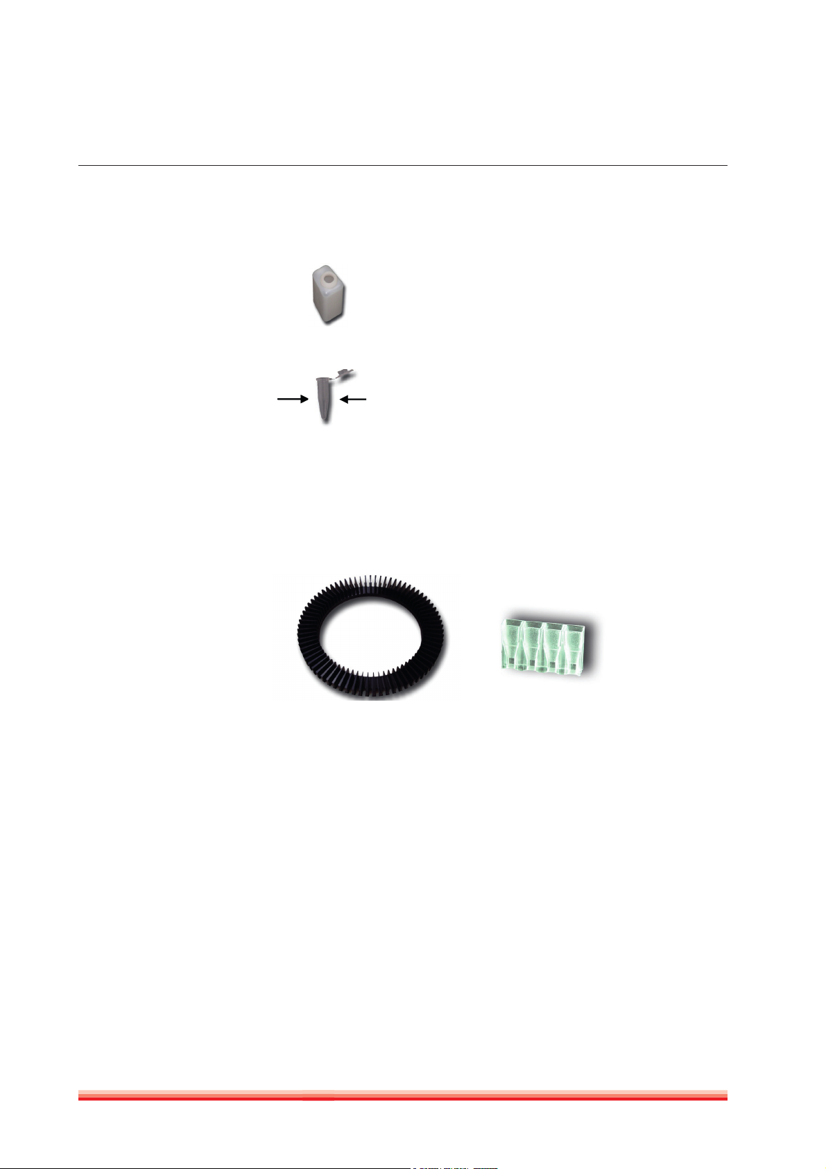
FIGURE 5
Reagent bottle
FIGURE 6
Serum cup
FIGURE 7
Outer Carousel
Empty Bottles can be ordered from Human:
Cat. number 16900/2
1.5 ml Serum Cups can be ordered from Human:
Cat. number 16904
max 10,5 mm
2.4.3.2 Outer Carousel
The outer carousel can not be removed for loading. Graph 1.17 just gives a better
impression of what the outer carousel is like.
FIGURE 8
Cuvette Block
HumaStar 180 | Service manual
The Outer Carousel features
75 Positions for Cuvette Blocks
Each Cuvette Block contains 4 Cuvettes, for
one test each.
Total loading volume: Cuvettes for 300
Tests. These Cuvette Blocks are unique
and can only be ordered from Human:
Cat number 16900/1
2.4.3.3 Functions of the Carousels
Temperature control of Outer Carousel
The temperature control of the outer carousel is effected by thermo resistors,
connected to an electronic regulating circuit. Together with temperature
sensitive sensors connected to the same regulating circuit, a stable temperature
is provided to the cuvettes throughout the whole test run.

SYSTEM INTRODUCTION 19
Cooling Option of Inner Carousel
The cooling of the inner carousel is effected by cooled water circulating un-
derneath the inner carousel, within a closed spiral copper tube. This copper
tube is connected to an external cooling generator, the system is closed and
independent from a tap water connection.
Insulation
In order to prevent temperature – interferences between the (optionally) cooled
inner and the temp. controlled outer carousel, an insulation ring is dividing the
two carousels.
Rotation
Both Carousels are controlled and rotated independently, within a co-axial
mechanical system.
Besides keeping samples, reagents and test containers in stable temperature
environment, actually the main function of the carousels is to provide the
Y – movement of the source and target containers within the pipetting and
measuring system of HumaStar 180.
The carousels are rotated while other processes within the complete system are
being performed. By doing so, the time required for rotating and positioning the
carousels is not a critical factor in terms of process time and throughput.
The Inner Carousel is only to be rotated during pipetting steps, as described
under 2.4.3.
It is rotated in either clockwise or counter clockwise direction and provides the
source containers required for a specific pipetting step to be positioned precisely
underneath the probes.
The Outer Carousel is to be rotated during pipetting steps as described under
2.4.3.
Additionally, the outer carousel is to be rotated during measurement steps as
described under 2.4.4
For pipetting, it is rotated in either clockwise or counter clockwise direction
and provides the target containers required for a specific pipetting step to be
positioned precisely underneath the probes.
For measurement steps, it is rotated in either clockwise or counter clockwise
direction and provides the target containers required for the measurement step
to be positioned precisely at the entrance position of the Linear Photometer
street.
20
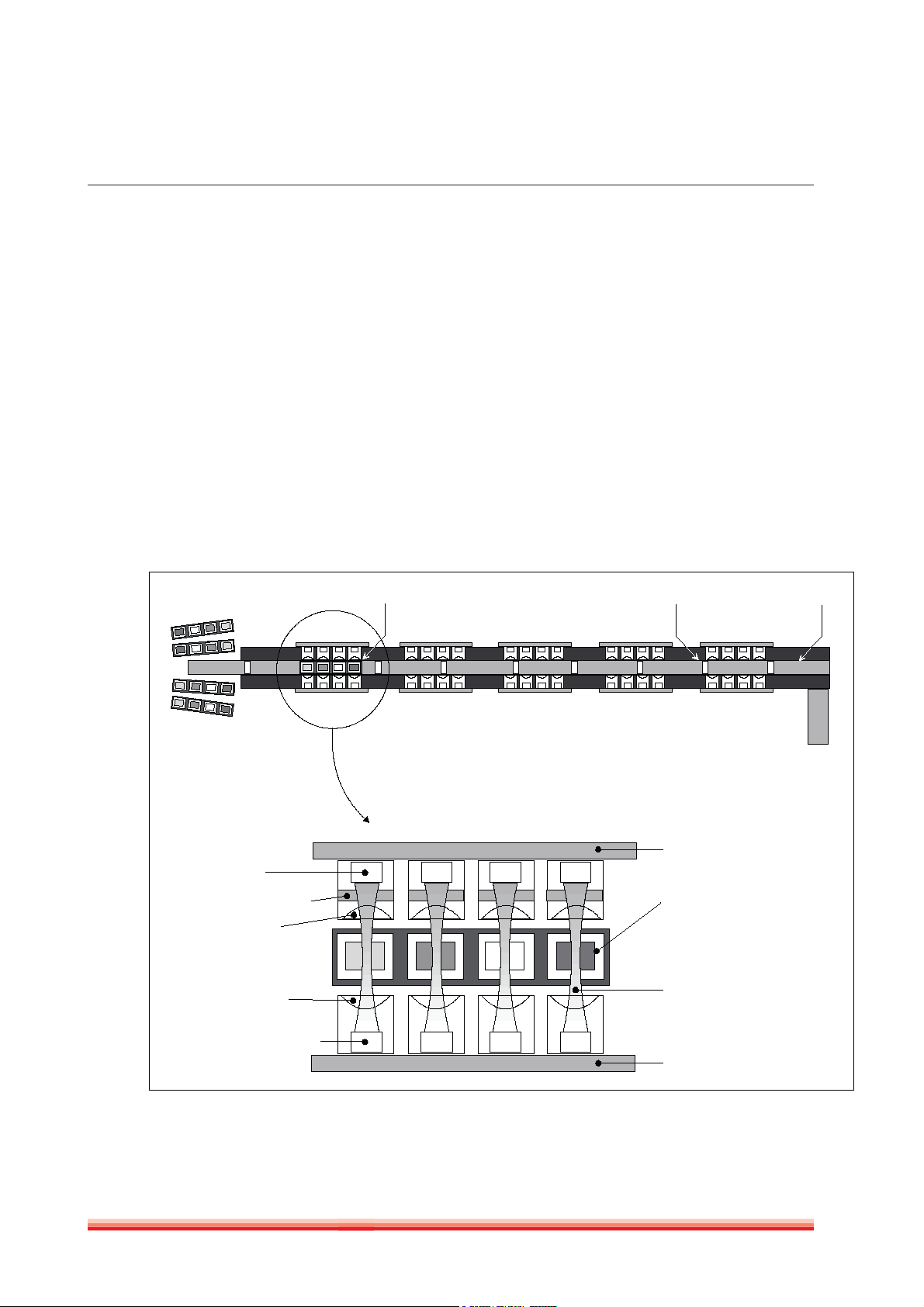
2.4.4 MEASUREMENT SYSTEM
HumaStar 180 is fitted with a unique Linear Photometer, featuring 20 independent measurement
channels for fast and accurate reading of test results in the cuvettes.
These 20 channels are organised in 5 groups of 4 channels each, whereas each group of 4 channels
is controlled by two electronic boards: One light emitting board and one detection board. These
are directly connected to the central Process Manager
Each of the 5 light emitting boards is fitted with 4 light sources (LED, light emitting diodes) and
the respective control electronics.
Each of the 5 detection boards is fitted with 4 detectors (Silicon Diodes) and the respective signal converter electronics, as well as with a RS 232 port which connects it with the Process Manager.
FIGURE 9
Measurement
system
Cuvettes in
outer carousel
Detector
Interference Filter
Optics (lens)
Optics (lens)
1 Cuvette block in
Reading Position
Cuvette Transport
Notch
Detection board
Cuvette Block
Light beam
Cuvette Transport
Belt
Cuvette
Transport
Motor
Light source "LED"
HumaStar 180 | Service manual
Light emitting board

SYSTEM INTRODUCTION 21
For reading, the cuvette block is transported from the outer carousel through the
linear photometer by a transport belt.
Depending on the wavelength required for the measurement, the cuvette block
will be positioned into the 4 light beams of the respective photometer block.
The light emitted by the LED’s is directed through a focusing lens. This lens
ensures a light beam, which is as parallel as required for having homogenous
measurement conditions.
While passing the cuvettes, respectively the liquid in the cuvettes, a part of the
light energy is being absorbed by the liquid in the cuvette. The remaining light
energy is now passing another lens and the respective interference filter and is
then being measured by the detectors.

22
HumaStar 180 | Service manual

ELECTRONICS 23
3 ELECTRONICS
- Schematic Diagrams
3.1 Introduction
This chapter gives information on the electrical and electronical components of
the Human system.
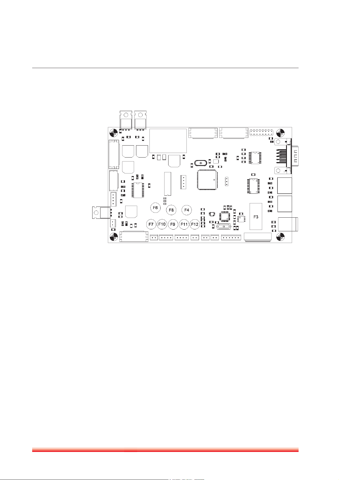
FIGURE 10
3.2 Schematic Diagram of Electronics
24
FIGURE 11
HumaStar 180 | Service manual

SERVICE SOFTWARE “EULY SERVICE” 25
4 SERVICE SOFTWARE “EULY SERVICE”
4.1 Introduction
This chapter gives the instructions on how to test functionality of all
independent modules of HumaStar 180 by using the Service Software
“EulyService”.
4.2 Installation of Euly Service
EULY SERVICE REQUIRES EXCEL 2000 ™ and will not work with older versions !
Copy the Service-Software-Folder to your local harddrive.
Start Microsoft Excel ™.
Open the file “EulyService.xls”.
Activate macros (set the security-level accordingly).
Microsoft Excel ™ will display a new Menu point “EulyService”.
4.3 Serial Settings
Set the serial port by selecting the menucommand “EulyService” -> “Serial
Settings”.
4.4 Script
A script consists of a string of commands, which are explained in this section of
the Service manual.
26
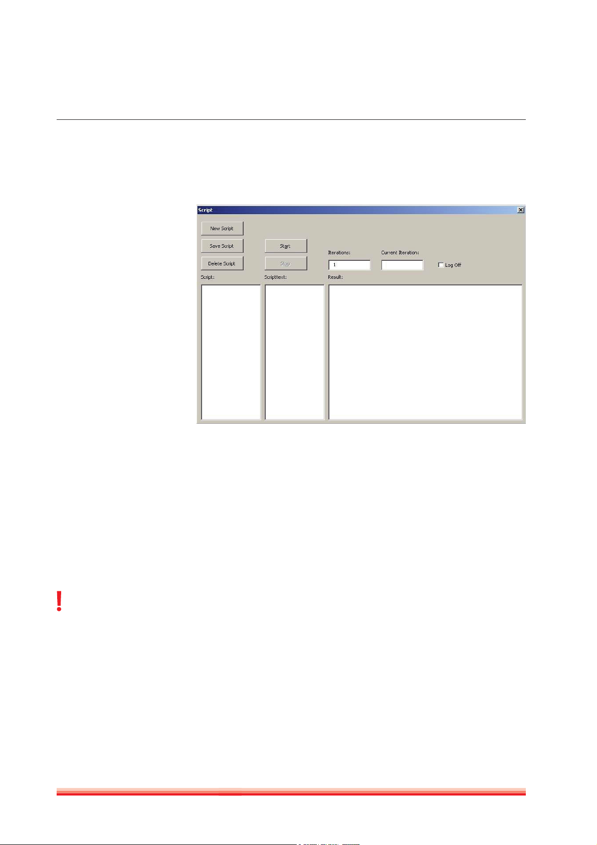
The menucommand “EulyService” -> “Script” launches displays the following
screen.
FIGURE 12
EuLy Service Script
Screen
List of prede-
fined saved
scripts, if
there is an
y
Contents of
predefined
saved scripts,
if there is any
Result window of
tests performed
In the list „Scripts:“ a script can be selected.
In the field „Scripttext:“ the text of the selected script is shown.
In the field „Iterations:“ the number of iterations can be entered.
By clicking „Start“ the selected script is started.
In the field „Result:“ the results are shown.
By clicking „Stop“ the script is stopped.
Script features a command set that allows service personnel to check and
confirm functionality of modules of HumaStar 180. Every single module and it’s
sub-functions can be checked independently.
When processing commands,
Euly Service does not check
for sensors ! It is the responsibili-
ty of the Service engineer to make
sure, that only command strings
are being entered, that can not
damage mechanical parts.
HumaStar 180 | Service manual
Script requires command strings that determine the module, the subfunction
and the actual command for the respective function.
A command – string consists of:
- Module Code
- Command
- Parameter
The Module codes, Commands and Parameters are explained on the following
pages (all letters are case sensitive !)
 Loading...