

Human Humalyzer 2000 User manual
Humalyzer
2000
Introduction
Principles
Photometer
Temperature
Flowcell
Display,
System
Troubleshooting..
Power
Photometer
Vacuum
Temperature
Main
Internal
Keypad
Display
Serial
Error
nn
of
Operation
...........
contro!
and
Vacuum
Keypad,
Control...
Supply
Pump
Control
PCB..
Printer
...
...
Port
Messages
Table
of
Contents
...
.
Pump
and
Thermal
enteresse
and
Pump
..
..
Service
..
Printer.....
Control
PCB
...8
1
5
10
11
Manual
Specifications
Replacement
Diagrams...
Block
PCB
Layouts
Main
Pump
Interface
Printer
Incubation
Schematics
Main
Pump
Interface
Printer
Incubation
...
Parts
Diagram
PCB
Control
PCB
PCB
......
PCB
Control
PCB
PCB
...
...
PCB
....
block
PCB
...
PCB
.
.....
block
PCB...
ns
40
Service
Calibration...
Procedures
Opening
Cleaning
Flowcell
Flowcell
Flowcell
Valve
Vacuum
Lamp
Filter
Filter
Calibration
Restore
Restore
Temperature
Absorbance
the
the
Tubing
Adjustment
Disassembly
Tubing
Adjustment
replacement.
Replacement
Label
an
Calibration
Filter
Calibration....
Instrument....
semen
Flowcell
Replacement..
Labels
Calibration
......
....
..
.
Data
....
..
..
Replacement
sorbance
Linearity
.
~
...
15
17
17
Rev. B 7/94

Rev.
B
Introduction
The
instrument
wavelengths
filters. A removable
built-in
standard.
well
tube
vacuum
as 1 cm
stations.
Layout
Figure 1 shows
and
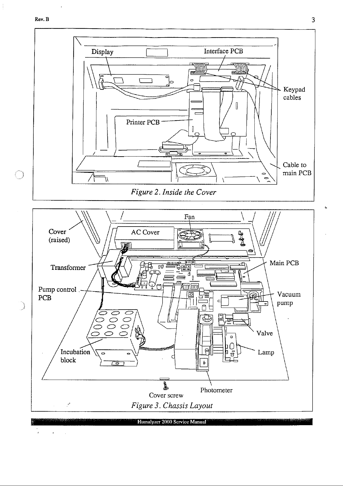
Figure 3 shows
The
interface
a
26-conductor
interface
interface
port
(DB-25S,
Finally, a 4-conductor
PCB
PCB
connector
is a
and
37°C
pump
When
the
square
Both
the
PCB
mounted
ribbon
supplies separate
via a 14-conductor
(DB-9P)
IDC)
connects
general-purpose,
incubation.
flowcell
and
flowcell
cuvettes.
the
exterior-of
the
cable
cable
provides
an
external
is
The
incubation
the
chassis
inside
and
connects
to
the
connects
bichromatic
Two
removed,
instrument
block
instrument,
layout.
the
header. A 2-conductor
power
ribbon
to
the
interface
the
photometer
additional
extremely
autoclavable
the
and
For
cover
for
the
cable
main
PCB
rapid
instrument
also
contains
the
read
Figure 2 shows
clarity,
behind
internal
terminated
PCB
via a 26-conductor
ready/sample
system
wavelengths
fluid
waste
bottle
accepts
well
some
cabling
the
front
cable
printer.
with
with a 4-conductor
PCB
are
sampling
with
standard
an
incubation
are
temperature
the
inside
arrangements
panel,
running
The
printer
IDC
ribbon
to
the
optional,
connects
interface
with
six
with
level
12
block
of
from
PCB
14-pin
cable.
cable
available
for a total
low
carryover.
sensing
mm
controlled
the
the
DIP
are
round
with
cover
are
not
to
the
main
connects
plugs.
The
parallel
and
header.
12
to
assembly,
main
PCB
PCB.
of
eight
A
supplied
tubes
as
round
37°C.
shown.
PCB
to
the
to
the
The
serial
port
1
by
All
AC
AWG
itself
is
mains
wires
feed
tied
directly
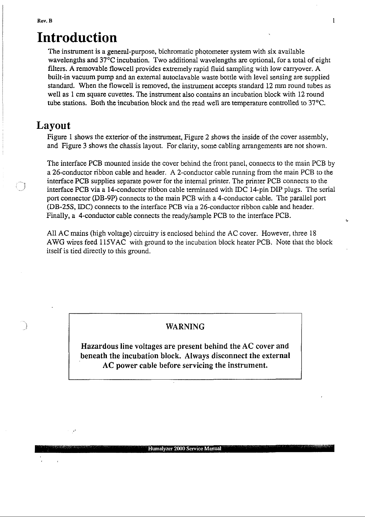
Hazardous
beneath
(high
115VAC
AC
voltage)
with
to
this
ground.
line
the
incubation
power
circuitry
is
ground
voltages
block.
cable
before
enclosed
to
the
incubation
WARNING
are
present
Always
servicing
behind
the
behind
disconnect
the
AC
cover.
block
heater
the
AC
instrument.
However,
PCB.
cover
the
external
Note
and
three
that
the
18
block
:
i
Humalyzer
2000
Service
Manual
Wi
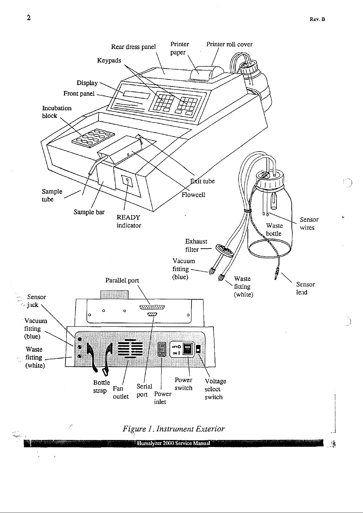
Front
Incubation
Display
panel
Rear
dress
panel
Printer
paper
Printer
roll
cover
Rev:
B
Sensor
ー
*
jack
Vacuum
fitting
(blue)
Waste
«.
fitting
(white)
M
indicator
Vacuum
fitting
Parallel
Bottle
SP
port
/
Fan
outlet
Serial
Port
(blue)
|
Power
inlet
Exhaust
filter
—__
Power
switch
—
g
Voltage
select
switch
Z
Waste
fitting
(white)
Sensor
wires
$
へ
Sensor
lead
Figure
*
Humalyzer
1.
Instrument
2000
Service
Exterior
Manual
ἐν
Κον.
Β
Display
ha
\
—
A
\
a
Printer
Г)
&
PCB
|
|
Interface
o
=
=
ーー
ES
PCB
\
|
l
N
\
~
|
>
=
Keypad
cables
Cable
main
to
PCB
P
PCB.
Cover
(raised)
Transformer
=
Incubation
trol.
Main
PCB
Vacuum
pump
Cover
Figure
Humalyzer
È
screw
3.
Chassis
2000
Service
\
Photometer
Layout
Manual
4
Principles
of
Photometer
The
light
from a tungsten-halogen
the
sample
filter
wavelengths,
filter
peak
voltage
compares
at
the
photodetector
phase
cap
(RC
end
absorbance
absorbance
it
wheel
passes
the
output
of
the
decay)
(offset).
contains.
and
photodiode. The
and
is
speed
in
front
of
produced
sampled
of the
comparator
output
comparator
determines
calibration
Operation
lamp
The
sealed box
controlled
the
photodetector,
by
the
photodetector.
voltage
is
proportional
output
to
enables a 16
is
the
base
(gain).
on
filter
wheel
to
the
output
to
the
proportional
of
the
Another
is
passed
the
approximately 3 rps
an
intensity
log (10
potentiometer
horizontally
opposite
contains
infrared
The
voltage
of
an
exponential
bit
counter
of
to
the
for
side
of
eight
optical
is
then
in
an
the
light,
absorbance.
absorbance)
is
though
the
interference
under
switch
capacitor
8254
used
the
read
well
filters
software
triggers a sampling
fed
to a comparator
decay
programmable
whereas
The
and
to
the
resistance
is
adjust
tube
or
flowcell
and
contains a rotating
of
various
control.
circuit.
width
used
the
high-end
timer.
across
to
adjust
As
each
of
which
The
The
of the
the
the
the
pulse
positive
log
Rev.
low-
B
=
Temperature
The
incubation
(025*C):
oscillator
centered-at
drive
the,
this
signal
Power
resistors
opto-triac.
employed
located
on
“Flowcell
An
integral
means
pinch
to
wires
PCB
of a solid-state
valve
the
flowcell.
built
to
indicate a full
These
U14A.
+2.5
CLK2
at
2.08
A red
for
the
the
cell
and
DC
is
opened
into
control
block
and
thermistors
The
waveform
V.
Schmitt
input
of
kHz,
the
located
LED
read
on
located
well
PCB.
Vacuum
vacuum
Sample
the
pump
vacuum
for a precise
(or
bottle
condition
read
well
are
maintained
are
multiplexed
at
U14A
triggers
U4.
37°C
the
except
U11
The
microprocessor
set
point.
bottom
on
the
that
of
block
driver
Pump
maintains a constant
air)
cap
sensor
are
interval
is
drawn
used
on
the
circuit
in
waste
at
at
0.5
second
is a sawtooth
convert
the
through
conjunction
this
heats
incubation
PCB
illuminates
U10
applies
vacuum
on
the
pump
under
microprocessor
the
flowcell
bottle.
37°C
by
means
rate
into
the
of
approximately
to a square
the
block
12VDC
control
with a detector
wave
system
are
switched
when
heat
on
an
external
PCB . A
control,
and
into
to
(raw)
circuit
of
thermistors
feedback
1.2
for
current
maintain
is
on. A similar
across
to
the
waste
path
Vpp
amplitude
reversal
the
to
115VAC
heater
waste
solenoid-operated
apply
on
the
bottle,
bottle.
(10k
of
and
frequency
via
system
resistors
by
this
vacuum
Sensor
pump
control
an
to
of
is
.
..
]
“Display,
A
24x
Keypad,
2:line
membrane
interface
cover
PCB
and
are
character
switch
keypads
via a 14-pin
connected
and
Liquid
are
DIP
the
to
Thermal
Crystal
sealed
cable.
interface
Display
behind
The
PCB.
Humalyzer
Printer
(LCD)
the
front
tails
of
the
printer
The
2000
Service
is
mounted
panel
Keypad
assembly,
Manual
inside
overlay.
switch
The
layers
consisting
the
LCD
are
cover.
Two 4 x
connects
fed
a
of
4
to
the
through
the
20-column
Rev.
B
5
thermal
connected
System
The
27256
incorporating a real-time
also
Almost
intervals
printer,
to
the
the
interface
Control
instrument
EPROM. A battery-backed
maintains
all
and
is
based
the
digital
I/O
pulse
date
timer.
printer
PCB
on
clock
and
is
accomplished
widths
are
PCB,
and
metal
via a 14-pin
the 8 bit
Z80
microprocessor.
non-volatile
is
used
store
time. A static
with
measured
using
supports,
DIP
cable.
RAM
data
RAM
chip
an
8255
the
is
mounted
The
(random
such
as
calibration,
(6264)
Programmable
counter
is
channels
to
the
software
access
used
memory)
test
for
Peripheral
of
an
rear
dress
is
permanently
chip
setups,
temporary
Interface.
8254
programmable
panel
and
stored
(MK48T08)
samples,
storage.
Time
is
and
in
a
6
Troubleshooting
The
instrument
section,
each
outlined.
incorporates
subassembly
or
solid-state
component
electronics
group
in
a-very
is
discussed,
reliable
possible
field-proven
problems
design.
and
solutions
In
Rev.
B
this
are
Power
The
power
voltage
bridge
+15
VDC
diode
regulates
A
"dead"
on
the
voltage.
power
rear
panel
fuse
holder
fuse
puller,
Use
only
If
voltage
present,
Supply
supply
supplied
BR2.
The
and
-15
bridge
main
cable
BR1,
this
down
instrument
PCB
If
there
and
and
lift
mounted
or
carefully
the
recommended
is
present
the
diode
consists
to
the
center
VDC
which
to
may
or
transformer.
is
no
open
the
at
bridge
of a transformer,
transformer
tap
is
for
analog
provides
+5
VDC
be
just a blown
voltage
the
instrument.
AC
cover
on
the
inside
pry
it
fuse.
J6,
check
BR1
is
converted
used
as a reference
circuitry.
+12VDC
for
the
logic
Also,
present
out
or
at
Remove
off
towards
of
the
with a small
Do
not
for
input
BR2
may
two
diode
to
for
Another
(raw,
and
other
fuse.
However, a blown
the
voltage
J6,
check
the
the
front
rear
panel.
screwdriver.
substitute
voltage
have
failed.
bridges,
36
VAC,
regulators
transformer
11-13
VDC
low
select
the
two
other
on
switch
fuse.
#4
screws
of
the
Locate
rating!
VR3, VR4,
and
three
center
voltage
tapped,
VR4
and
output
nominal)
control
fuse
setting
To
replace
holding
instrument.
the
blown
Install a 0.6A
Replace
and
VRS.
regulators.
which
VRS,
supplies
to
the
circuits.
may
must
the
fuse,
the
Locate
fuse
and
3AG
the
If
feeds
which
11
system,
indicate a problem
match
disconnect
AC
cover
the
remove
slow
AC
cover.
no
voltage
Line
diode
provide
VAC
and
the
line
to
double
it
blow
is
to
VR3
the
the
clip
with
fuse.
a
Photometer
The
photometer assembly
.
Read
.
Lamp
.
Photometer
*
Filter
The
read
well
fixed
plate
and a spring
tube
or
flowcell
the
cell
heat
PCB. A stainless
spring
The
life
inactivity.
replacement
shock
and
plate
lamp
of
the
to
lens
into
is
tungsten-halogen,
instrument,
However,
as
the
instrument
brackets
well
assembly
and
brackets
PCB
wheel
assembly
the
and
is
detected
the
light
since
under
output
simply
can
be
and
motor.
serves
loaded
by
to
plate.
an
steel
path
between
rated
the
lamp
heavy
becomes
may
necessitate
hold
the
examined
cell
heat
hold
the
tube
Mechanical
opto
pair
plunger
the
at
6V,
is
turned
usage
low
the
near
lamp
lamp
and
as
several
component
PCB
or
flowcell
adjustments
(phototransistor
in
the
bottom
opto
pair.
10W,
and
off
automatically
lamp
remains
the
end
replacement
lens
in
alignment
is
intended
of
its
centered
and
center
on
service
due
systems:
are
not
IR
LED)
of
to
after
for
longer
life.
to
filament
with
the
on
the
cell
required.
mounted
the
cell
block
be
maintenance
30
minutes
periods
In
addition, a physical
breakage.
rest
of
block,
The
between
presence
at
the
forces a small
free
of
instrument
and
may
The
the
assembly.
a
of
ends
of
for the
require
lamp
The
a
Humalyzer
2000
Service
Manual
Rev.
B
'
7
brackets
be
completely.
ENTER.
wavelength,
volts.
measure
regulator
lamp.
The
Because
attempt
The
neoprene
contained
maintenance
extreme
may
low,
provide
centered
The
If
all
the
circuitry
Refer
photometer
the
to
modify
filter
wheel
belt.
in
humidity
be
compromised.
the
filter(s)
adjustments
on
the
light
path.
To
check
instrument
position,
or
most
voltage
to
the
PCB
photodetector
turns
The
the
wheel
free
for
and
of the
at
the
on
the
section
contains a photodiode, a very sensitive
the
photometer
on a shoulder
filter
wheel
are
for the
or
may
life
temperature
Run
be
in
both
The
low
lamp
prints
the
voltages
main
“Lamp
suspect.
the
voltage
lamp
terminals.
PCB
and
related
itself
of
metal
of
the
are
test # 186
horizontal
lamp
must
be
output,
detected
are
(Q6
Replacement”.
PCB.
screw
requires
deposition
instrument.
encountered,
Refer
run
voltage
for
each
filter.
low,
the
If
the
and
VR1)
circuitry
shaft
no
type
as
described
to
the
service
lamp
is
However,
and
vertical
replaced
test
lamp
may
solid-state,
and
adjustments.
construction
optical
if
output
#186.
is
above.
Press
for
each
The
voltages
is
the
likely
voltage
be
the
driven
in a non-ideal
characteristics
If
procedure
dimensions,
becomes
MENU,
filter.
The
printout
should
suspect.
is
much
problem.
op
amp
it
should
by
the
The
and
only
“Filter
lower
circuit
require
filter
optical
are
intended
environment
one
or
Replacement”.
so
that the
low
then
be
between 2 and
As a final
than
Otherwise,
and
wheel
interference
on
one
two
filter
filament
or
the
type
186
shows
4.5
phototransistors.
no
service.
motor
to
be
or
more
voltages
lamp
and
the
check,
VDC,
replace
Do
via
a
filters
where
filters
can
fails
press
10
the
the
not
are
Flowcell
If
proper
liquids
The
flowcell
flowcell
for
cleaning
Replacement"
Erratic
caused
section
coupling
readings
by
Valve
The
valve
the
pinch
vacuum
the
valve
is
clogged.
care
is
taken
have been
should
tubing
"Flowcell
tubes.
line
is
has
and
parts
and
(excessive
improper
Ensure
uses a short
valve
tubing
from
operating,
See
the
to
clean
sampled,
be
become
“Flowcell
installation
Tubing
the
section
the
cleaned
damaged
replacement.
dither)
Replacement’.
that a leak-free
length
may
be
Luer
fitting.
but
the
“Valve
the
flowcell
flowcell
regularly
Refer
Disassembly”.
may
of,
or
of
silicone
blocked.
Press
flowcell
Tubing
between
itself
as
or
the
to
be a result
failure
Check
seal
tubing.
To
PURGE
is
clogged.
Replacement”.
uses,
should
described
flowcell
the
of
is
made
check
require
is
service
of
the
flowcell
the
insertion
and
If
the
for
and
If
you
especially
little
in
"Cleaning
clogged,
procedures
trapped
tubing
that
valve
operates
clogged
listen
for
do
not
after
or
no
the
the
flowcell
“Flowcell
air
in
the
flowcell.
or
coupling
depth
no
of
the
tubes
are
but
valve
tubing,
aspiration.
hear
aspiration,
highly
proteinaceous
maintenance.
Flowcell".
can
flowcell
kinked
If
the
be
disassembled
Tubing
This
can
tubes.
tubes
or
pinched
|
no
sample
unscrew
If
you
hear
the
is
the
valve
be
See
the
into
the
off.
drawn
aspiration,
up,
flowcell
tubing
Humalyzer
2000
Service
Manual
8
Rev.
B
Vacuum
The
runs
fittings.
only
at a higher
very
Adjustment”.
than
the
event
section
Pump
vacuum
continuously,
until
high
usual,
pump
Check
that the
finger-tight.
or
lower
altitudes,
If
but
otherwise
that
the
"Exhaust
"Temperature
The
temperature
recalibration.
“Temperature
In
Calibration”.
and
and
pump
you
probably
tubing
Do
not
level
than
the
vacuum
the
vacuum
works),
exhaust
Filter
filter
Replacement".
Control
control
the
system
event
calibration
Pump
control
is
over-tighten
the
trimpot
pump
gets
is
Control
PCB
have a leak
firmly seated
instrument,
is
taking
the
exhaust
wet
very
must
should
in
on
the
such
may
require
longer
filter
due
to a waste
stable
and
be
verified
PCB
require
the
vacuum
barbs
plastic
Luer
as
on a shelf,
adjustment.
to
achieve
is
likely
bottle
ordinarily
or
no
maintenance.
side.
Check
and
all
fittings
fittings!
clogged
spill,
does
re-established,
or
See
full
vacuum
not
If
if
and
it
must
If
the
waste
are
tight.
the
waste
the
instrument
the
section
(runs
should
be
replaced.
require
adjustment
refer
to
the
vacuum
bottle
Turn
bottle
“Vacuum
much
be
replaced.
the
section
cap
the
is
located
is
used
longer
See
or
pump
and
fittings
at
In
the
Humalyzer
2000
Service
Manual
Rev.
B 9
Main
Swat
PCB
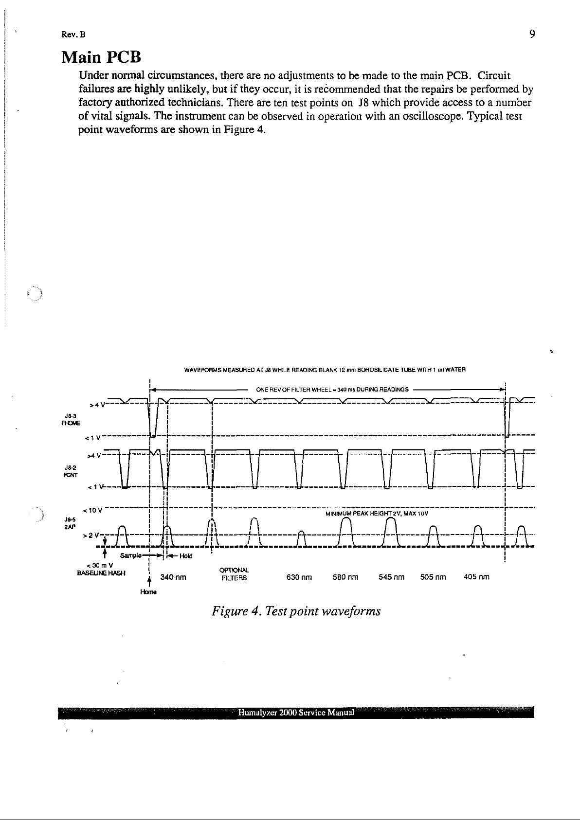
Under
failures
factory
of
point
normal
authorized
vital
signals.
waveforms
are
circumstances,
highly
unlikely,
technicians.
The
instrument
are
shown
there
but
if
There
can
in
Figure
are
they
occur,
are ten
be
observed
4.
no
adjustments
it
is
test
in
to
be
recommended
points
on
J8
operation
made
which
with
to
the
main
that the
an
repairs
provide
oscilloscope.
PCB.
be
performed
access
Typical
Circuit
by
to a number
test
ses
FROME
Je2
FONT
J8-5
Ar
BASELINE
à
VTT
<1V°
s>4 V 一 二 ~ £
<1¥
sov"
>2V
+
NA
<30mV
Sample
HASH
I
に
1
a
ET
m
i
RTE
一
一
mi
4
340
Home
WAVEFORMS
tin
Hold
nm
MEASURED
一
1
U
få
i
444
ET
OPTIONAL
FILTERS
Figure
AT
J8
ONE
REV
一
мм
=
- -
A
Г
Ja
tr
4.
Test
WHILE
OF
630
READING
FILTER
WHEEL = 340
1
m
TÃO
nm
point
BLANK
12
mm
BOROSILICATE
ms
DURING
그
그
~
MINIMUM
ーーー
PEAK
HEIGHT
ーーーー
LT.
580
nm
waveforms
READINGS
Af
キーーーーーーー
も
2V,
ーー
ゴ
545
TUBE
ーー
---
MAX
トーーーーー
nm
WITH 1 mi
MT
ee
İz
ヒーーーーーー
ヒ
10V
キ
ゴ
ー
505
nm
WATER
一
~
ゴ
ーーーーーー
000”
405
M
1
ー
キ
ーーーー
ーーーー
nm
νὶ
mm
ヒト
コ
ーー
1
1
©
+
mmm
ーー
一
Humalyzer
‘
‘
2000
Service
Manual
i
aa
10
Rev.
B
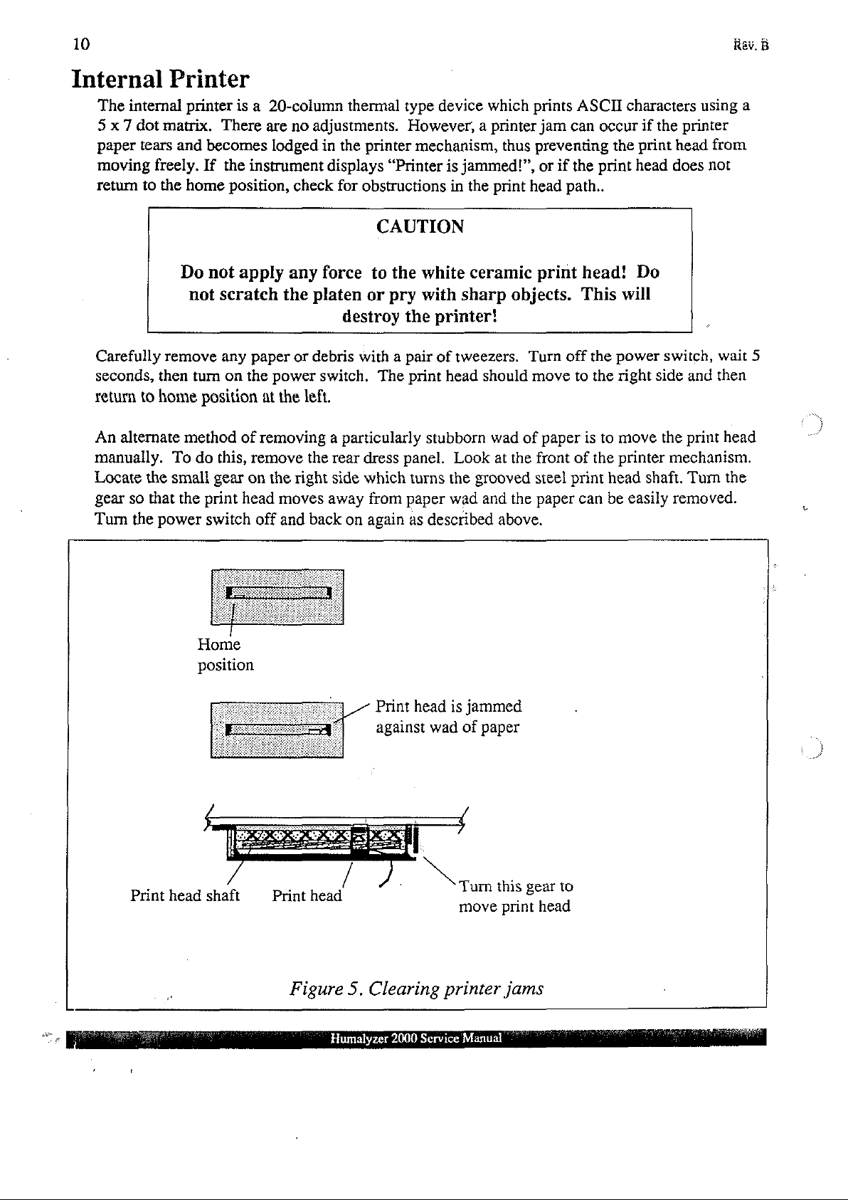
Internal
The
internal
5 x 7
dot
paper
tears
moving
return
Carefully
seconds,
return
An
manually.
Locate
gear
Turn
freely.
to
the
then
to
home
alternate
the
so
that
the
power
Printer
printer
matrix.
and
home
Do
not
remove
turn
method
To
small
the
is a
There
becomes
If
the
position,
not
apply
scratch
any
on
position
of
do
this,
gear
print
head
switch
20-column
are
no
lodged
instrument
check
thermal
adjustments.
in
the
displays
for
obstructions
type
printer
“Printer
CAUTION
any
force
the
platen
paper
or
debris
the
power
at
removing a particularly
remove
on
the
off
the
left.
the
right
moves
and
back
switch.
away
to
or
destroy
with a pair
The
rear
dress
side
which
from
on
again
the
pry
the
panel.
paper
device
However, a printer
mechanism,
white
with
printer!
of
print
stubborn
turns
as
described
which
thus
is
jammed!”,
in
the
print
ceramic
sharp
tweezers.
head
should
wad
Look
at
the
grooved
wad
and
above.
prints
jam
preventing
or
head
print
objects.
Turn
move
of
paper
the
front
steel
the
paper
ASCII
can
if
the
path..
head!
This
off
to
is
of
print
can
characters
occur
the
print
will
the
power
the
right
to
move
the
printer
head
be
easily
if
the
print
head
head
does
Do
switch,
side
the
mechanism.
shaft.
removed.
using
printer
from
not
wait
and
then
print
head
Turn
the
a
5
Print
head
İ
Home
position
shaft Print
head
Figure
|
Print
against
5.
Clearing
head
wad
printer
is
jammed
of
Turn
move
paper
this
.
print
jams
gear
head
to
Humalyzer
2000
Service
Manual
Rev.
B
Keypad
The
keypad
by
pressing
causes
Press
the
ENTER
Display
The
display
controller.
There
are
is
a
sealed
AUX,
instrument
is a 24 x 2
The
no
then
to
end
display
adjustments.
membrane
pressing
to
beep
the
test.
line
super
should
all
and
be
switch
keys
except
display
twisted
clearly
legible
layer
which
CLEAR
a
character.
nematic
at
is
not
Press
liquid
all
crystal
times,
serviceable.
and
ENTER.
CLEAR
display
with
no
You
Note
and
module
dark
can
that
the
display
spots
test
each
with
or
stray
the
keypad
key
clears.
integral
dots.
11
Serial
By
amale
is
The
Contact
Port
using a special
2400
pinout
cable, a serial
9-pin
DB-style
connector
baud, 8 bits, 1 stop
for
the
serial
port
1.
2
3
49
your
GND
TX
RX/DTR
NC
distributor
to
obtain a serial
bit,
and
is:
printer
using
or
RS-232
no
parity.
computer
signals
printer
cable.
with a serial
in
anon-standard
port
may
pinout.
be
connected.
The
data
This
format
is
Humalyzer
2000
Service
Manual
12
Rev.
B
Error
Error
help
usually
The
Lamp
Lamp
Printer
Printer
Messages
messages
the
operator
indicated.
following
Failure
Output
Paper
Not
error
Low
Jam
Ready
are
displayed
locate
messages
the
problem.
when
the
instrument
If
error
messages
indicate
The
were
eter"
The
voltages
due
possible
lamp
does
detected
under
lamp
does
were
to
degraded
interface
not
for
all
"Troubleshooting".
not
detected
filters.
"Troubleshooting".
The
internal
path.
If
connecting
The
external
out
of
paper
indicate
printer
the
paper
the
an
incorrectly
path
printer
printer
or
otherwise
fails
to
appear
or
appear
filter
appear
for
See
paper
path
is
clear,
PCB
attached
unable
wired
operate
component
to
positions.
to
some
the
to
correctly.
frequently, a hardware
problems.
illuminated
be
illuminated
filter
section
is
obstructed.
Check
the
interface
to
the
to
external
at all.
See
the
positions.
"Photometer"
the
14-pin
PCB.
parallel
print.
port
If
chronic,
cable.
They
are
intended
problem
Low
voltages
section
sufficiently.
Clear
This
the
DIP
or
serial
"Photom-
Low
is
possibly
under
paper
cable
port
this
may
to
is
is
Waste
Empty
Filter
Wheel
Vacuum
is
Full!
Waste-Press
Leak
XX
Err
Enter
The
waste
bottle
for
Check
See
The
wheel.
Q12
eter"
The
prescribed
at
is
empty,
shorts.
the
cable
"Waste
instrument
Check
and
Q13
under
self-check
all
connections.
material
On
is
"Troubleshooting".
length
has
check
the
pump
from
Full
!",
cannot
the
photometer
on
the
photometer
routine
of
time.
reached
the
sensor
control
the
pump
above.
correctly
LED
was
unable
Check
the
level
cable,
PCB,
control
detect
PCB.
for
check
pulses
board
See
to
achieve
leaks
jack,
PCB
sensors.
and
internal
U2A,
to
the
from
and
the
phototransistors
the
section
vacuum
at
the
waste
If
the
Q2
and
main
the
"Photom-
within
bottle
waste
wiring
U3:
PCB.
filter
the
and
Humalyzer
2000)
Service
Manual
Rev.
B
The
decoding
following
logic
error
at
U6,U7,
messages
and
indicate
U16.
U3
possible
can
be
checked
failure
of
by
the
NV
RAM
U3,
substitution.
or
the
address
13
**Memory
Filter
Water
Do
Do
Labels
Values
Temp
ABS
Error**
7&8
Test
Test
Clrd
Reset
210!
212!
The
was
The
section
, o The
The
found.
The
found.
checksum
deleted.
stored
stored
stored
stored
filter
"Restore
water
temperature
See
the
absorbance
See
the
failed
when
labels
were
Filter
Labels”.
absorbances
calibration
section
section
"Restore
calibration
"Restore
a
stored
corrupted
were
corrupted
test
values
Calibration”.
values
Calibration".
was
or
not
were
were
recalled.
found,
or
not
The
See
found.
corrupted
corrupted
test
the
or
or
not
not
14
Rev.
B
Service
Opening
Refer
allow
sensor
work
lift
the
Do
To
chassis,
to
Figure
access
lead
surface.
the
front
cover
not
reinstall
open
force
taking
Procedures
the
Instrument
3.,
Instrument
to
the
inside
from
the
Locate
of
the
cover
with a suitable
the
cover
the
cover,
care
of
rear
panel.
and
remove
upward,
backwards.
reverse
to
clear
the
Interior.
the
instrument.
Move
the
cover
taking
object.
Damage
the
procedure.
incubation
The
cover
is
hinged
Disconnect
the
instrument forward
screw
care
block
from
to
clear
to
the
cover
Carefully
and
the
at
the
the
power
until
the
underside
the
incubation
or
fittings
lower
the
Luer
rear
panel,
cable,
the
front
of the
block
may
cover
fitting.
until
Replace
and
the
tubing, and
edge
front
and
photometer.
result.
it
seats
the
can
be
raised
the
overhangs
edge.
on
Gently
the
screw.
to
the
Prop
Humalyzer
2000
Service
Manual
Rev.
B
15
Cleaning
The
overnight,
clogging
accurate,
the
To
一
the
flowcell
end
of
the
repeatable
flowcell,
clean
the
1.
Purge
2.
Aspirate
flowcell
3.
Aspirate
4.
Aspirate
for 3 minutes.
5.
Purge
Flowcell
should
it
flowcell:
be
of
shift,
flowcell
results.
is
extremely
with
air
several
for 3 minutes.
15
ml
0.1N
with
air
cleaned
and
tubing
when
when
and
If
reagent,
difficult
for
at
least 5 seconds.
ml
of
flowcell
of
distilled
sodium
for
hydroxide
at
least 5 seconds.
the
storing
valve
serum,
to
remove
cleaning
water
instrument
the
flowcell.
tubing.
Cleaning
or
other
and
its
solution.
then
purge
(NaOH
).
|
will
not
be
Proper
presence
with
Allow
cleaning
is
extremely
proteinaceous
can
Allow
air
for 5 seconds.
the
solution
used
affect
the
for
an
extended
will
help
important
fluid
is
test
solution
to
remain
period,
to
prevent
to
obtaining
allowed
to
results.
to
remain
in
the
e.g.
dry
in
in
the
flowcell
6.
7.
8.
Aspirate
3
minutes.
Purge
If
seen
the
flowcell
flowing
with
0.1N
hydrochloric
at
least
is
to
into
the
15
ml
be
removed
waste
acid
of
deionized
for
bottle.
(HCI).
Allow
water.
storage,,
Otherwise,
the
purge
leave
solution
with
the
to
air
until
flowcell
remain
no
more
filled
in
the
with
fluid
flowcell
can
be
water.
for
Humalyzer
2000
Service
Manual
16
Rev.
B
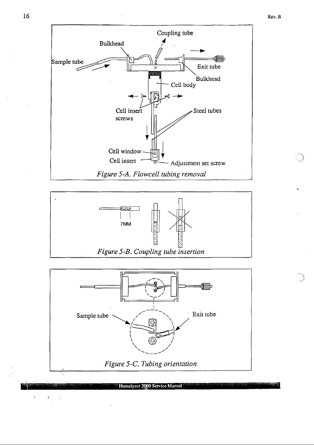
Sample
tube
Bulkhead
W
Cell
Screws
Cell
Cell
Figure
Coupling
A
Î
a
п
o
insert
window
insert
5-A.
Flowcell
——
tubing
tube
.
f
Exit
Bulkhead
Cell
body
Steel
Adjustment
removal
set
_
=
tube
tubes
screw
Nas
Sample
tube Exit
Sar
\
x
©
/
/
tube
Figure
5-C.
Humalyzer
Tubing
2000
Service
orientation
Manuâl
 Loading...