

Human HumaCount Plus Service manual

Service Manual
!"#$%&"'(
&
!"#$%&"'()*+,-
Hematology Analyzer
Revision 3.0
Cat.-No.: 16400/2
!

($./0)&1)%&'(0'(2
1 INTRODUCTION......................................................................................................................................... 5
1.1 Name and serial number ..................................................................................................................... 5
1.2 Intended use .......................................................................................................................................5
1.3 Integrated software.............................................................................................................................. 5
2 FUNCTIONAL DESCRIPTION ....................................................................................................................6
2.1 Main electronic parts of the analyzers .................................................................................................. 6
2.1.1 Cell-counter Probes....................................................................................................................... 7
2.1.2 HGB Head ....................................................................................................................................7
2.1.3 Volume Opto Board....................................................................................................................... 8
2.1.4 Amplifier Boards............................................................................................................................ 8
2.1.5 Measurement & Pneumatic Interface Card (MPNIF) .................................................................... 10
2.1.6 Safe configuration E
2.1.7 High Voltage Board (HVB)........................................................................................................... 11
2.1.8 Graphic LCD Module................................................................................................................... 12
2.1.9 Keyboard Panel........................................................................................................................... 13
2.1.10 Start key & glowing LED.............................................................................................................. 13
2.1.11 Pressure & Liquid Sensor Board (PCPRO).................................................................................. 13
2.1.12 Stepper Motor Opto Boards......................................................................................................... 14
2.1.13 Valve Driver Boards .................................................................................................................... 14
2.1.14 Main Board (MB4) ....................................................................................................................... 15
2.1.15 DimmPC Module ......................................................................................................................... 15
2.1.17 Switching Power Supply .............................................................................................................. 16
2.1.18 Floppy Disk Drive ........................................................................................................................ 16
2.1.19 Parallel and USB Printer Ports..................................................................................................... 16
2.1.20 Serial Port................................................................................................................................... 16
2.2 Main mechanic and fluidic parts of the Analyzer................................................................................. 17
2.2.1 Aspirating tip ............................................................................................................................... 18
2.2.2 Dilutor ......................................................................................................................................... 18
H&V moving unit (XY) ............................................................................................................................... 19
2.2.4 Volume Meter Tube (xVM) – HUMACOUNT PLUS only............................................................... 20
2.2.5 Peristaltic Pump .......................................................................................................................... 20
2.2.6 Chamber(s*)................................................................................................................................ 21
2.2.7 Valves (1-5, 6-10*, 11-15) ........................................................................................................... 21
2.2.8 Washing head ............................................................................................................................. 21
2.2.9 Puffer reservoir ........................................................................................................................... 22
2.2.10 Tubes.......................................................................................................................................... 22
2.3 Assembled Analyzers........................................................................................................................ 23
2.3.1 HUMACOUNT PLUS Electronic Block......................................................................................... 23
2.3.2 HUMACOUNT PLUS Mechanic and Fluidic Block........................................................................ 24
2.3.3 HUMACOUNT Electronic Block................................................................................................... 25
2.3.4 HUMACOUNT Mechanical and Fluidic Block ............................................................................... 26
2
PROM board (IDEPROM) ........................................................................... 11

3 OPERATION OF THE FLUIDIC SYSTEM ................................................................................................. 27
3.1 Waste Full Checking ......................................................................................................................... 27
3.2 Sampling process.............................................................................................................................. 28
3.3 Aspirating tip washing process........................................................................................................... 29
3.4 Diluting process................................................................................................................................. 30
3.5 Lysing process .................................................................................................................................. 31
3.6 WBC counting process ...................................................................................................................... 32
3.7 RBC counting process....................................................................................................................... 33
3.8 Washing processes ........................................................................................................................... 33
3.9 Cleaning process............................................................................................................................... 34
4 ADJUSTMENT.......................................................................................................................................... 35
4.1 Mechanical settings........................................................................................................................... 35
4.1.1 Opto wheel setting ...................................................................................................................... 35
4.1.2 Aspirating tip setting.................................................................................................................... 36
4.2 Hardware settings ............................................................................................................................. 36
4.2.1 Adjustment of the liquid detector sensitivity.................................................................................. 36
4.2.2 Amplifier offset setting ................................................................................................................. 37
5 CHECKING OF PROPER OPERATION.................................................................................................... 38
5.1 Self test............................................................................................................................................. 38
5.1.1 Self Test Screens........................................................................................................................ 38
5.1.2 Normal range of Self test parameters .......................................................................................... 39
5.1.3 Troubleshooting Guide for Self test.............................................................................................. 39
5.2 Service Menu .................................................................................................................................... 40
5.2.1 Entering to Service Menu ............................................................................................................ 40
5.2.2 Main Service Menu...................................................................................................................... 40
5.2.3 Edit Service Contact.................................................................................................................... 40
5.2.4 Device Information ...................................................................................................................... 40
5.2.5 Service Calibration...................................................................................................................... 40
5.2.6 Software Settings........................................................................................................................ 41
5.2.7 Service Testing Menu.................................................................................................................. 42
5.2.8 Valve Test Menu ......................................................................................................................... 42
5.2.9 Display and Keyboard Test.......................................................................................................... 43
5.2.10 Stress mode................................................................................................................................ 43
5.2.11 Miscellaneous settings ................................................................................................................ 43
5.2.12 Rescue Code for Multi-user Mode ............................................................................................... 43
6 SERVICE OPERATIONS.......................................................................................................................... 44
6.1 Opening of the instrument ................................................................................................................. 44
6.2 Removing/Installing DimmPC ............................................................................................................ 45
6.2.1 Removing DimmPC..................................................................................................................... 45
6.2.2 Installing DimmPC....................................................................................................................... 45
6.3 MDA (Monochrome Display Adapter) emulation mode....................................................................... 45
6.4 Key BIOS settings for correct operation ............................................................................................. 46
6.4.1 BIOS Settings of DimmPC........................................................................................................... 46
6.4.2 Exit Menu.................................................................................................................................... 47
6.5 DOS Functions on the Instrument...................................................................................................... 47
6.6 Error messages................................................................................................................................. 48
6.6.1 Error code list.............................................................................................................................. 48
6.6.2 Message code list ....................................................................................................................... 51
2/77 Service Manual HUMACOUNT & HUMACOUNT PLUS

6.7 Problems related to Warning flags..................................................................................................... 52
6.8 Possible Causes of Noise.................................................................................................................. 53
6.8.1 Contaminated reagent ................................................................................................................. 53
6.8.2 Bad earth grounding.................................................................................................................... 53
6.8.3 External electrical noise............................................................................................................... 53
6.8.4 Internal noise sources ................................................................................................................. 54
7 MAINTENANCE........................................................................................................................................ 55
7.1 Weekly Maintenance by User ............................................................................................................ 55
7.1.1 Cleaning the washing head ......................................................................................................... 55
7.2 Periodic Maintenance by Service....................................................................................................... 55
7.2.1 Check Self test and Device statistics ........................................................................................... 55
7.2.2 Cleaning and Greasing Dilutor Block ........................................................................................... 55
7.2.3 Checking and Lubricating Dilutor Piston Tips ............................................................................... 55
7.2.4 Cleaning and Lubricating Needle Moving Mechanics ................................................................... 55
7.2.5 Checking and Replacing Washing Head ...................................................................................... 55
7.2.6 Checking and Replacing Peristaltic Pump Tube........................................................................... 55
7.2.7 Checking of the Power Supply..................................................................................................... 55
7.2.8 Bleaching of Fluidic System......................................................................................................... 55
8 SPARE PARTS......................................................................................................................................... 56
9 APPENDICES........................................................................................................................................... 61
9.1 Warning Flags................................................................................................................................... 61
9.2 Serial Communication Protocol (V2.x) ............................................................................................... 62
9.2.1 General Description..................................................................................................................... 62
9.2.2 Format of Packages Sent by HUMACOUNT PLUS/HUMACOUNT .............................................. 63
9.2.3 Format of Acknowledge of the Receiver ...................................................................................... 63
9.2.4 Detailed Description of Packages ................................................................................................ 63
9.2.5 INIT package............................................................................................................................... 63
9.2.6 DATA package............................................................................................................................ 64
9.2.7 Transmission Example ................................................................................................................ 66
9.3 Recommended kit of tools ................................................................................................................. 67
9.4 HUMACOUNT PLUS tubing schematic..............................................................................................68
9.5 HUMACOUNT tubing schematic........................................................................................................ 69
9.6 HUMACOUNT PLUS Cabling Diagram.............................................................................................. 70
9.7 HUMACOUNT Cabling Diagram........................................................................................................ 71
9.8 HUMACOUNT PLUS Amplifier, High voltage & HGB Boards ............................................................. 72
9.9 HUMACOUNT Amplifier .................................................................................................................... 73
9.10 HUMACOUNT PLUS Amplifier PCB .................................................................................................. 74
9.11 HUMACOUNT Amplifier PCB ............................................................................................................ 75
9.12 H&V, DIL, VM, LD Opto and Valve Boards......................................................................................... 76
9.13 Electronic part PCBs ......................................................................................................................... 77
9.14 Revision History ................................................................................................................................ 77
Service Manual HUMACOUNT & HUMACOUNT PLUS 3/77

(34-)-456)+678)9+:;<
4/77 Service Manual HUMACOUNT & HUMACOUNT PLUS

=) >'(?&@"%(>&'
Since
!"#$%&"'() */"2
and
!"#$%&"'(
have so much common characteristics, we
cover both instruments in a common Service Manual. Information herein applies for both
analyzers unless otherwise noted.
To be well up in the instruments,
A+6:-6)B6:5)834-)C:;,:+)D:B67,++E
to have the knowledge
for servicing the instruments perfectly and avoid extra costs and wasting precious time.
This
!"#$%&"'() */"2F!"#$%&"'() 26BG4D6) #:;,:+)
analyzers, the operation of the fluidic systems, the adjustments and settings and very important information for
the Service Personnel about the service operations and possible problems.
contains the functional descriptions of both
=H=) ':C6):;5)-6B4:+);,C96B
':C6I !"#$%&"'()*/"2F!"#$%&"'(
26B4:+)'JHI
Every instrument has its own serial number, which is printed on the rear panel label and it can be
read out from Device Information or from the Self test submenu. This serial number is write
protected by HUMAN.
Hematology Analyzer
=HK) >;86;565),-6
!"#$%&"'() */"2F!"#$%&"'(
diagnostic use. The compact instruments were developed for small to medium size labs.
!"#$%&"'()*/"2
!"#"$%&'"(#)"(*+,,+-&'.(/0()"%1#+,+.2(31$1%"#"$4(*$+%(1(56(7,(-)+,"(8,++!(41%3,"9
! WBC – LYM# - MID# - GRA# - LYM% - MID% - GRA% (three-part WBC differential)
! HGB – RBC – HCT – MCV – RDW – MCH – MCHC
! PLT – MPV – PCT – PDW
can process 60,
hematology analyzers are fully automated cell counters for !"# $!%&'
!"#$%&"'(
can process 30 samples per hour and they are intended to
=HL) >;86MB:865)-J78N:B6
The integrated software controls the instrument operations, displays, stores, recalls data, and allows the User to
perform QC and calibration procedures and modify the user settings. The software version number can be read
out from the Device Information or from the Self test submenu.
Instrument software (V1.7 and above) is absolutely ()*+,#-".#)*-/0,#it can detect what type of instrument is used
and it will control the analyzer according to the hardware, without any user or service help. Every
*/"2F!"#$%&"'(
software version can be updated by the latest release available from HUMAN.
!"#$%&"'(
Service Manual HUMACOUNT & HUMACOUNT PLUS 5/77
K) 1"'%(>&'$/)@02%?>*(>&'
KH=) #:4;)6+6D8BJ;4D)A:B8-)J7)836):;:+EO6B-
!"#$%&"'()*/"2F!"#$%&"'(
1. Cellcounter Probe(s)
2. HGB Head
3. Volume Opto Board)– only for
4. Amplifier Board
5. Measurement & Pneumatic InterFace Card (MPNIF)
6. Safe configuration E
2
PROM board
7. High Voltage Board
8. Graphic LCD Display Module
9. Keyboard Panel
10. Start key & glowing LED
11. Pressure & Liquid Sensor Board
12. Stepper Motor Opto Boards
13. Valve Driver Boards
14. Switching Power Supply
15. MB4 Main Board with DimmPC
16. Floppy Disk Drive
17. Parallel Port (optional USB printer port)
18. Serial Port
Hematology Analyzers consist of the following electronic parts:
)!"#$%&"'()*/"2
B&43,12(L44"%8,2
M"28+1$!(=1'",
I&.)(J+,#1."
<+1$!
C"14D$&'.(:'&#
J+,D%"(K3#+
<+1$!F
A",,?+D'#"$
=$+8"E4FG(H(I> <
)"1!
>$13)&?(@AB
B&43,12(C+!D,"
L%3 ,&* &"$(< +1$ !
=1$1,,",(=$&'#"$
;"$&1,(B1#1(=+$#
+3#&+'1,(:;<
=$&'#"$(=+$#
=+$#
;#1$#(U"2
=+-"$
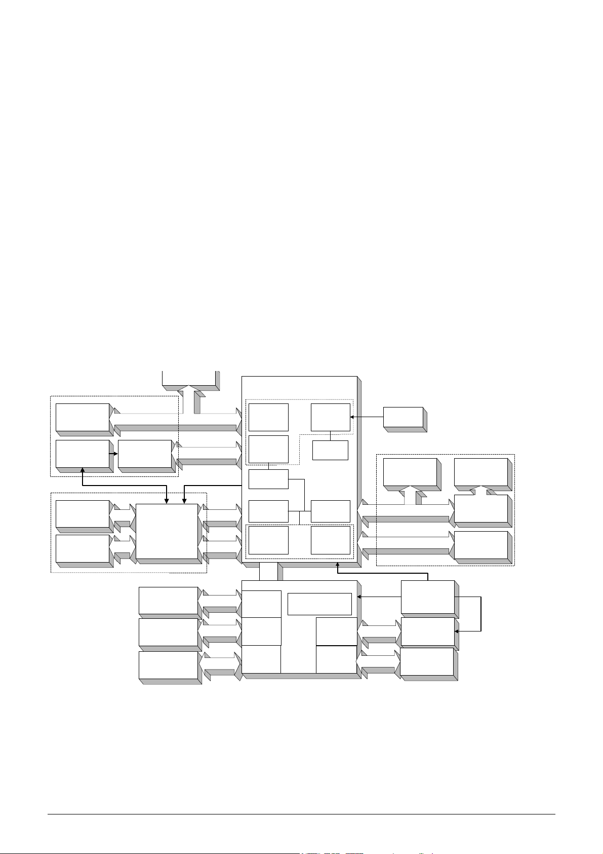
.%)&0"%1%23'4'!2%01)35$'623%"7)$%
,#23"# 88%"'9 '.!:6;
O;L
8D4
=OA
T=>L
?+'*&.D$1#+$
A+'*&.W
5
=PKC
X
C+#+$
A+'#$+,,"$4
H(B$&N"$4
T=>L
J1,N"
O'#"$*1?"
H(B$&N"$4
B&%%=A
PLCZ(T,14)B&4U
PQAA
@&R81##"$2
T,+332(B&4U
O'#"$*1?"
M"28+1$!
&'#"$*1?"
M"28+1$!
O'#"$*1?"
CBL
"%D,1#+$
JOBXK
PLC
LSB
A+'N"$#"$
B&.,(OSK(H
O;L(8D4
O'#"$*1?"
!"#$%&&#"'(#) "*'+,-.(/
=1$1,,",(=+$#
O'#"$*1?"
;"$&1,(=+$#
O'#"$*1?"
:;<
O'#"$*1?"
;1*"(A+'*W
5
=PKC
X
=$"44D$"(H
@&VD&!(;"'4+$
<+1$!
B$&N&'.(=+-"$
;-&#?)&'.(=+-"$
T,+332(B&4U
=;S5(M"28+1$!
&'#"$*1?"
;D33,2
B$&N"
='"D%1#&?(;24#"%
Y""!,"(C+N&'.
C"?)1'&4%(H
B&,D#+$(<,+?U
;#"33"$(C+#+$
K3#+(<+1$!4
J1,N"(B$&N"$
<+1$!4
<=.>,-=:?'!@=AB<=.>,-=:?
1*23%&'"!3#4+"3%!'"-*#5*'36#7!-,&-8
6/77 Service Manual HUMACOUNT & HUMACOUNT PLUS
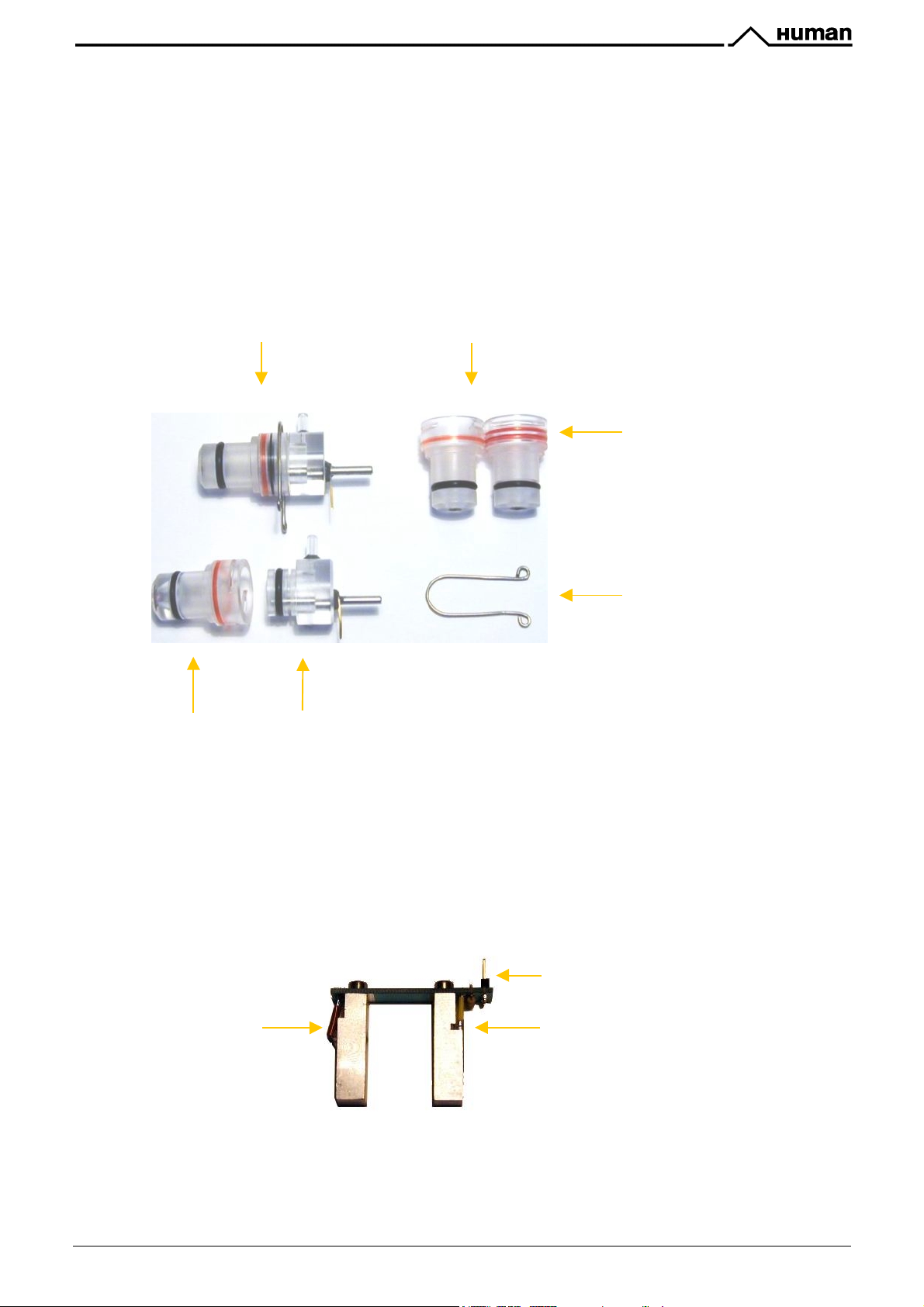
KH=H=) %6++PDJ,;86B)*BJ96-
Impedance method is used for determination of volume and number of cells. In this method a known volume of
dilution is drawn through a small aperture. Constant current is passed through the aperture from one side to the
other. When a cell passes through the aperture, it causes a change in resistance, which generates a voltage
pulse.
The amplitude of the voltage pulse is proportional to the ratio of cell volume per aperture volume. This is used to
determine the volume of cells. The number of cells can be obtained by counting the pulses.
! In the
! In the
!"#$%&"'() */"2
3$+8"( -&#)( 0\( 7%( 13"$#D$"W( <+#)( )1N"( 1( .$+D'!( ","?#$+!"( 144"%8,2( 1'!( :R4)13"!( %"#1,( *&]&'.( 14( &#( &4
shown in the next figure.
!"#$%&"'(
the RBC probe in the
(#)"$"(&4(+',2(+'"(A",,?+D'#"$(=$+8"9(#)"(13"$#D$"(4&^"(&4(0\( 7%(_(#)&4(&4(#)"( 41%"(14
!"#$%&"'()*/"2
#)"$"(1$"(#-+(A",,?+D'#"$(=$+8"49([<A(3$+8"(-&#)(/\\(7%(13"$#D$"Z(1'!(P<A
.
Assembled Cellcounter Probe
Measuring tube
The aperture is made of ruby and it is moulded into the measuring tube. The correct sealing around the aperture
is very important for measurements.
Ground electrode assembly
Measuring tubes
Red rings mark
measuring tubes:
K'"9(P<A((_(((0\(7%
Q-+9([<A(_(/\\(7%
U-shaped metal fixing
KH=HK) !Q.)!6:5
Hemoglobin head is placed at the bottom of the WBC chamber in the
the measuring chamber in the
(TSL235). The Photo Detector converts the light to frequency. The HGB concentration is a logarithmic function of
this frequency measured by the FPGA circuit of the MPNIF card.
LED
Service Manual HUMACOUNT & HUMACOUNT PLUS 7/77
!"#$%&"'(
. It contains: light source (LED) at 540 nm and Photo Detector
!"#$%&"'()*/"2R)
Connection to the amplifier
Light sensor
and at the bottom of
!"#$%&"'()*/"2
makes four kinds of HGB measurements (diluent measurements are performed on diluent
reagent):
! Sample dark measurement (before WBC counting)
! Sample light measurement (before RBC counting)
! Diluent light measurement (in WBC washing phase)
! Diluent dark measurement (immediately after the previous one)
The HGB result is calculated from these measurements by:
HGB " log [(CNT
!"#$%&"'(
HGB " log (CNT
diluentlight
does not perform any dark measurements (it is always zero), so this equation is simpler:
diluentlight
– CNT
/ CNT
diluentdark
samplelight
) / (CNT
)
samplelight
– CNT
sampledark
)]
C#'2#3'#D%2'#"'$8#&%'3E%'52&3"01%23'*##"'*0"52F')2G'1%)&0"%1%23'$G$8%H'I%$)0&%'3E5&'1)G
$)0&%' %""#"' 52' <J(' 1%)&0"%1%23K' :#"1)88GH' *##"' &E#08*' I%' $8#&%*' *0"52F' "%)8
1%)&0"%1%23&K
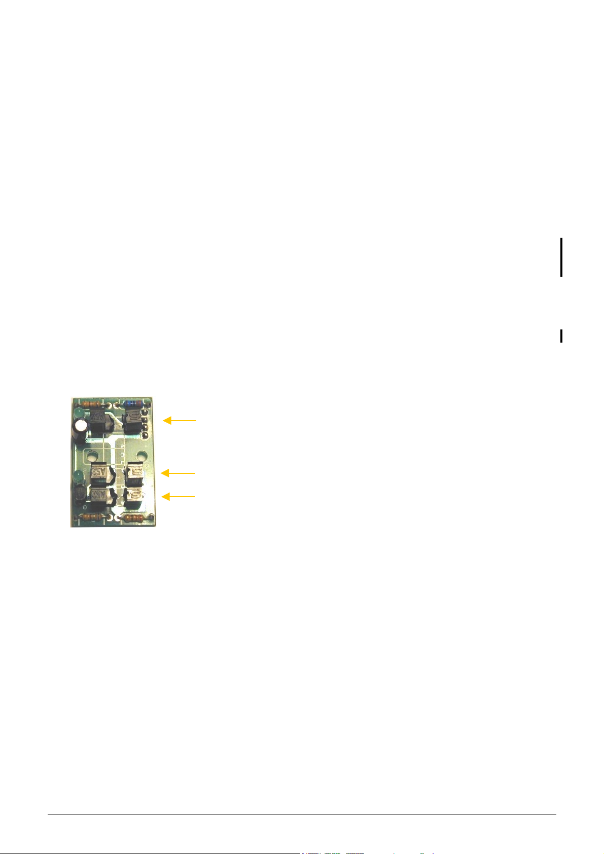
KH=HL) SJ+,C6)&A8J).J:B5
?E5&'I#)"*'5&'D"%&%23'#28G'52'<=.>,-=:?'!@=AK
It contains three opto switches which make possible to measure a constant volume of the diluted sample with a
special float. The volume opto board is connected to the amplifier board through the VM connector (on the other
side of this board).
Measurement is made between OM1 and OM3 – no
LED on, (OM2: gate opto is for bubble error
OM1: Top opto
prevention).
The upper LED is lit, when the float is between the
OM1 sensor.
OM3: Bottom opto
The lower LED is lit, when the float is between the
OM2 sensor, but OM3 sensor is not
OM2: Gate opto
KH=HT) $CA+4746B).J:B5!"#$%&"'()*/"2):;5)!"#$%&"'():CA+4746B)9J:B5-):B6)54776B6;8)*%.-
, but there are a lot of common
functional parts on them.
%JCCJ;
functional parts: amplifier board includes its own voltage regulator, the connection interfaces for HGB
head, for high voltage board and for MPNIF card.
In this board there is the current generator circuit, which works from 50 V measuring voltage (coming from high
voltage board) and the probe (DC) voltage is amplified with a voltage follower (output: ELV). Nominal measuring
current is
UVW)X$
.
The amplifier board includes the main 3-stage amplifier channel, which amplifies the input signal to the 0...5 V
range (this is the input range of the A/D converter, which is on the MPNIF card). The offset voltage is set by P1
potentiometer by the manufacturer.
$5Y,-8)836)J77-68)GJ+8:M6)J;+E)4;)D:-6)48)4-)J,8)J7)836)ZFP)[CS)B:;M6H
The test circuit makes possible to generate test pulses (with TEST and PLS signals through FETs) for checking
the proper operation of the amplifier channel.
8/77 Service Manual HUMACOUNT & HUMACOUNT PLUS
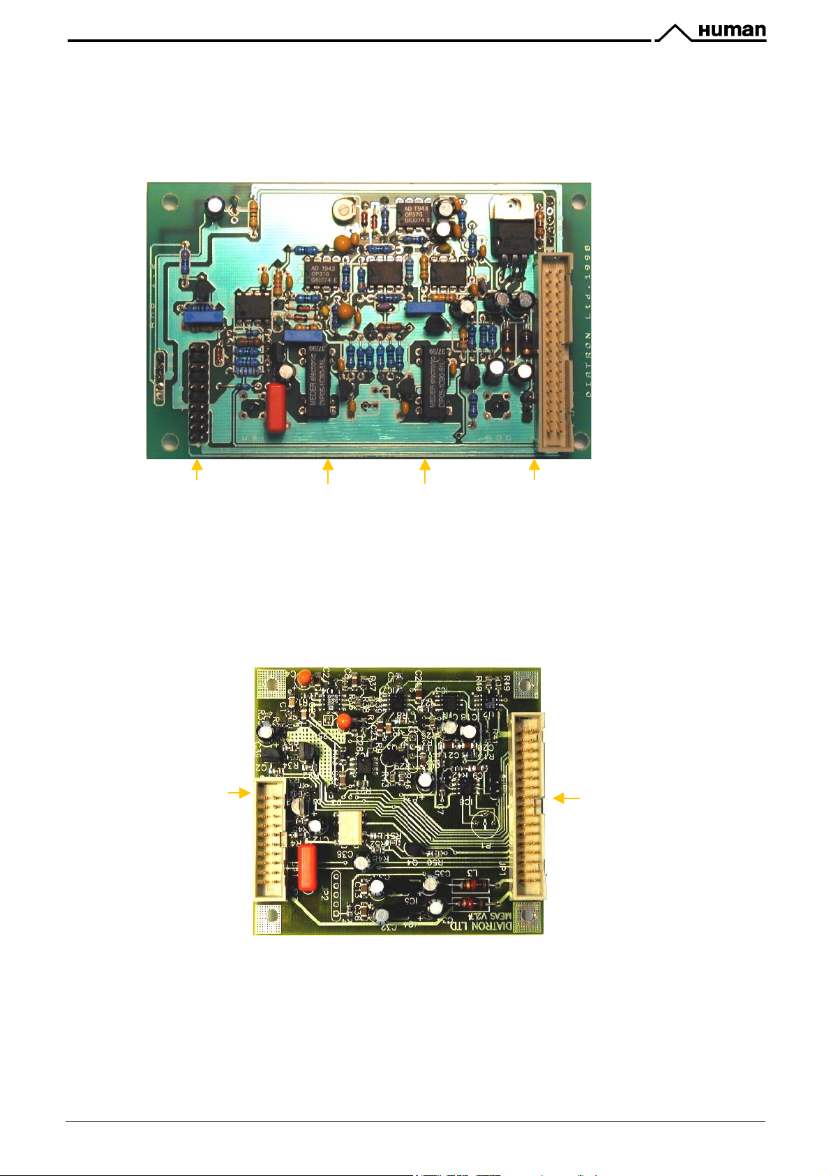
!"#$%&"'()*/"2):CA+4746B
board includes also the connection (JP2) for volume opto limiter.
In this board there are two reed relays on the input side: IC10 can select between the two channels (RBC, WBC)
with RSW signal; IC11 connects high voltage (from high voltage board) to the selected probe with HSW signal.
The DHON signal (from the MPNIF card) switches on the LED in the HGB head via a transistor (Q3), but the
Photo Detector in the HGB head is working continuously.
Connection. to the
high voltage board
!"#$%&"'():CA+4746B
Reed relays
board includes only one input connector for the chamber.
Connection to the MPNIF
card (AMP and DIGIO)
In this board there is no relay in the input stage, but there are two opto switches (U1, U3: TLP627) to connect
high voltage (from high voltage board) to the probe with HSW signal and isolate the input of the amplifier.
The RSW signal changes the gain (RBC, WBC) in the feed back of the second amplifier stage with U2 (MAX319)
analog switch.
The DHON signal (from the MPNIF card) switches on the LED and also the Photo Detector in the HGB head via
a transistor (Q3) that is why there is no dark HGB value in
Connection to the
high voltage board
!"#$%&"'(
.
Connection to
the MPNIF card
The other side of the amplifier boards includes special connectors for the chamber(s) and connector for the
HGB head (JP4).
Service Manual HUMACOUNT & HUMACOUNT PLUS 9/77
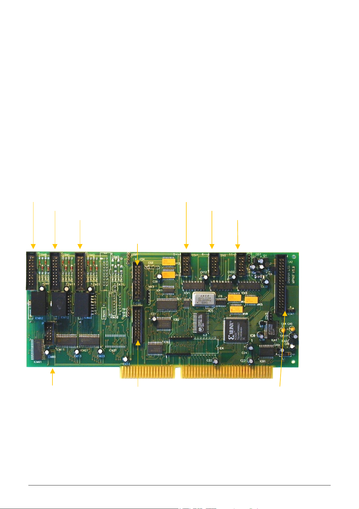
KH=H[) #6:-,B6C6;8)\)*;6,C:84D)>;86B7:D6)%:B5)]#*'>1^
(
)
#*'>1
card incorporates measurement processing, and also the pneumatic, display and keyboard functions in
one board.
In addition, this card has an
(monochrome display adapter) emulation mode, which allows the Service
#@$
Person to use the LCD like a computer monitor or checking the proper operation of the instrument’s main board.
The controller card is connected to the main board through the ISA bus. After power on the card holds the main
board in wait state (with
configuration E
that the
1*Q$
2
PROM located on the card, or from the safe E2PROM, located on the IDEPROM board. After
makes the I/O and memory address decoding and selects the actual part placed on the board:
–IOCHRDY
signal) until the
(micro-controller) configures the FPGA circuit from the
*>%)
! Video RAM for MDA (Monochrome Display Adapter) emulation and Graphics
! Card controller PIC
! Motor controller PICs (micro-controllers, controlling stepper motors)
The FPGA circuit also performs the main measurement data sampling and communication tasks. The board’s
A/D chip with its own sample/hold circuit makes the analog to digital conversion. After that the FPGA makes the
data processing and stores the results in a temporary FIFO memory. The results are sent to the PC main board
by DMA cycles.
With the internal registers of the FPGA the software can control the valves, the digital interface of the amplifier
and the controller PIC. The PIC makes displaying (even greeting screen at start-up) and keyboard scanning,
after the loading the configuration into FPGA.
CSM0: Connection to Horizontal motor
CSM1: Connection to Vertical motor
CSM2: Connection to Dilutor motor
CSV1: Connection to 1-5 valves
CSV2: Connection to 6-10 valves
CSV3: Connection to 11-16 valves
Valve 16 = PUMP
CSK: Connection
to keypad
CSP: Connection. to the liquid
& pressure sensor board
10/77 Service Manual HUMACOUNT & HUMACOUNT PLUS
CSD: Connection to
the LCD module
CSA1, CSA2: Connection
to the amplifier

KH=H_) 2:76)DJ;74M,B:84J;)0K*?&#)9J:B5)]>@0*?&#^
This board contains a 24FC256 serial E
2
PROM, which stores the FPGA’s configuration data, Safe greeting
screen and identity information about the instrument. Keeping the hardware identity information (OEM
information, model version: HUMACOUNT PLUS/HUMACOUNT) the IDEPROM makes possible to run the
correct software (HUMACOUNT PLUS or HUMACOUNT) and store the instrument’s serial number.
The IDEPROM is connected to the MPNIF card and it is write protected.
2
The data of the normal configuration E
PROM on the MPNIF card can be modified by the software, allowing to
change the FPGA functions. If there is any problem (e.g. power off) during this overwriting process, the
instrument will start in “Safe mode” (this is displayed on the LCD) and the FPGA will be configured from the Safe
2
PROM (IDEPROM card).
E
KH=HV) !4M3)SJ+8:M6).J:B5)]!S.^
High Voltage Board generates the backlight voltage (300Vrms, 180 kHz) for CCFL (cold-cathode fluorescent
lamp) of the LCD, the aperture cleaning voltage (150Vdc), and the measuring voltage (50Vdc). The high voltage
board is connected to the system through the amplifier board and the MPNIF card.
This unit contains INVC191 inverter, which is a high voltage, high frequency circuit producing suitable voltage for
CCFL of the LCD.
Connection
to amplifier
Connection
to LCD lamp
The CFSW digital signal (from the MPNIF card) controls the high voltage board, if it is high (1) the inverter is off,
if it is low (0) the inverter is on.
The MVON digital signal (from the MPNIF card) switches the measuring voltage (50 Vdc) on/off by an opto
switch.
L)"252FM' (%' $)"%708' N53E' &%"O5$52F' 3E5&' I#)"*' 52' )$35O%' &3)3%H' I%$)0&%' 3E%' E5FE' O#83)F%
+PQQR/')3'@,C'8)1D'$#22%$3#"'$)2'$)0&%'*)1)F%&'#"'%8%$3"5$'&E#$SK
:%O%"' #D%")3%' 3E%' )2)8GT%"' N53E#03' 3E%' @,C' I)$S85FE3' $#22%$3%*' 3#' 3E%' <R(H' I%$)0&%' 3E%
#O%"UO#83)F%'#2'3E%'#03D03'#7'3E%'<R('$)2'*)1)F%'3E%'<R('I#)"*')2*'3E%')1D8575%"K
Service Manual HUMACOUNT & HUMACOUNT PLUS 11/77
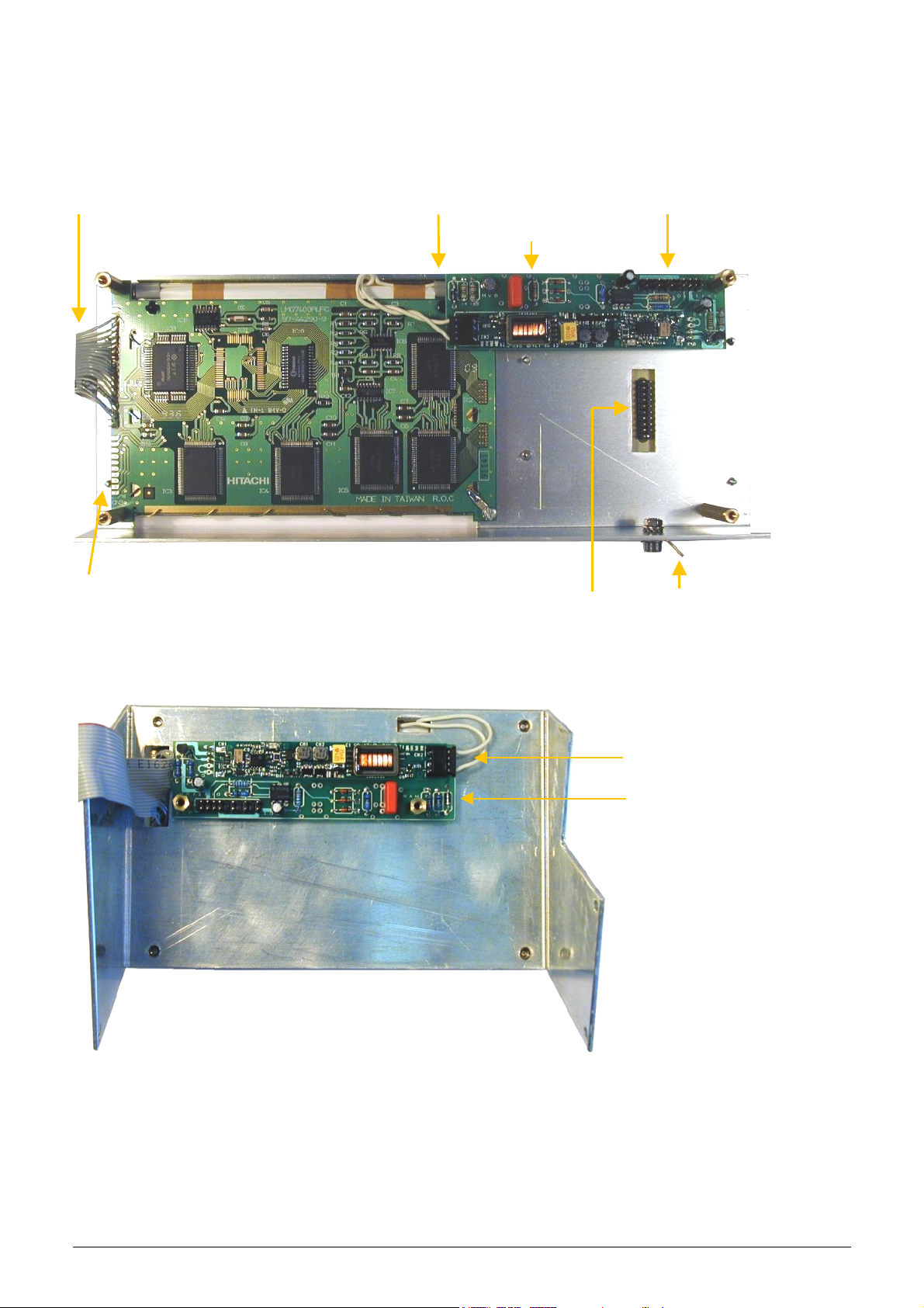
KH=HU) QB:A34D)/%@)#J5,+6
This module contains 240x128 dots LCD display (HITACHI LMG7400PLFC or SP14N002), the HVB and this is
the back panel of the keyboard module. LCD has a high voltage backlight lamp (the high voltage board
generates the required voltage).
LCD Connection to MPNIF
Temperature sensor
Connection to backlight lamp Connection to amplifier
High voltage board
Keyboard connection
Ground connection
In the
!"#$%&"'(
9:7#-;;28<*/#'=#
<=.>,-=:?'!@=A
the HVB is fixed onto the LCD display holding frame:
Connection to LCD
backlight lamp
HVB (Old version)
In the LCD module and on the MPNIF card there is a special temperature compensation circuit, which makes
possible to use the LCD module in wide temperature ranges with the adjusted contrast.
12/77 Service Manual HUMACOUNT & HUMACOUNT PLUS
KH=H`) a6E9J:B5)*:;6+
The analyzer has a 24-button foil keyboard including numerical keypad (0...9, .), cursor moving and OK buttons,
Delete and Help (?) keys and 6 function buttons, under the LCD display as it is shown in the figure below
(
!"#$%&"'(
KH=H=W) 28:B8)<6E)\)M+JN4;M)/0@
The Start key is a micro switch, connected to the MPNIF card (through the K&L ribbon cable). The glowing LED
indicates the actual status of the analyzer and it has three colors: red, green and amber (See User’s Manual).
The LED has three pins and the actual color depends on the controlled pins. The LED is also connected to the
MPNIF card through the K&L ribbon cable.
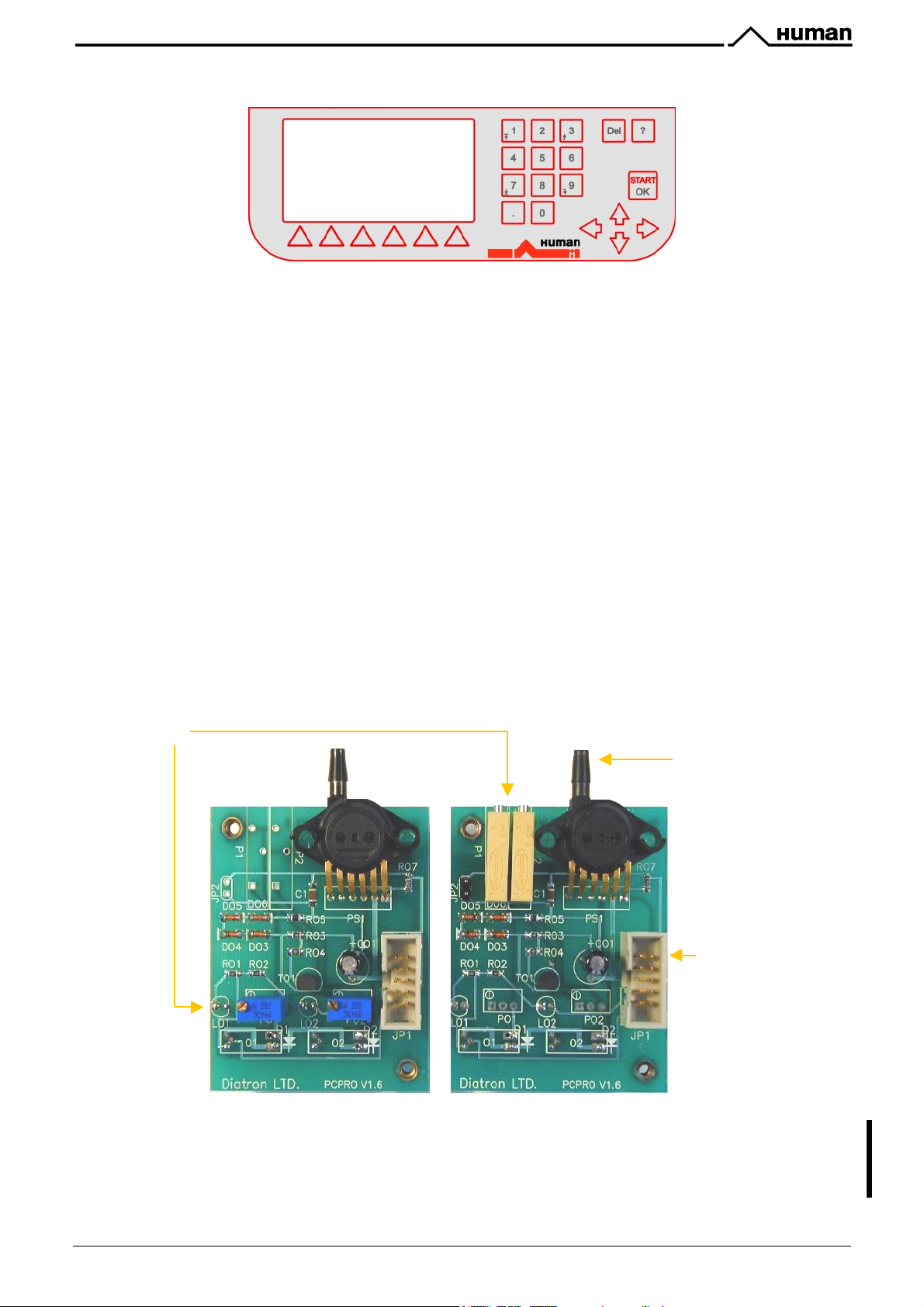
KH=H==) *B6--,B6)\)/4b,45)26;-JB).J:B5)]*%*?&^
This board contains MPX5100AP calibrated pressure sensor, which can measure the pressure of air. It has two
liquid detectors, for sensing diluent/cleaner and lyse reagents.
There are two potentiometers to adjust the sensitivity of both liquid sensors, but in different position for
!"#$%&"'() */"2
Diluent/Cleaner, the one on the right is for the Lyse detector sensitivity. The PCPRO board is connected to the
MPNIF card through the P ribbon cable.
keyboard panel):
and
!"#$%&"'(
(see the pictures below). The potentiometer on the left is for the
On the other side of the board there are two liquid detectors with indicator LEDs which show the actual state of
the sensors: the corresponding LED is on if no reagent in the tube.
!"#$%&"'()*/"2)\)!"#$%&"'()*%*?&
Potentiometers
Pressure
sensor
Connection
to P cable
?E%'D"%&&0"%'&%2&#"'3#8%")3%&'1)V5101'WX'R')2*'53'E)&'3E%'&)1%'D#N%"'O#83)F%')&'3E%'#D3#
&%2&#"&'E)O%K'C#'2#3'$#22%$3'E5FE%"'O#83)F%'3E)2'WX'R'3#'3E5&'I#)"*'I%$)0&%'53'$)2'*)1)F%
3E%'D"%&&0"%'&%2&#"K
Service Manual HUMACOUNT & HUMACOUNT PLUS 13/77
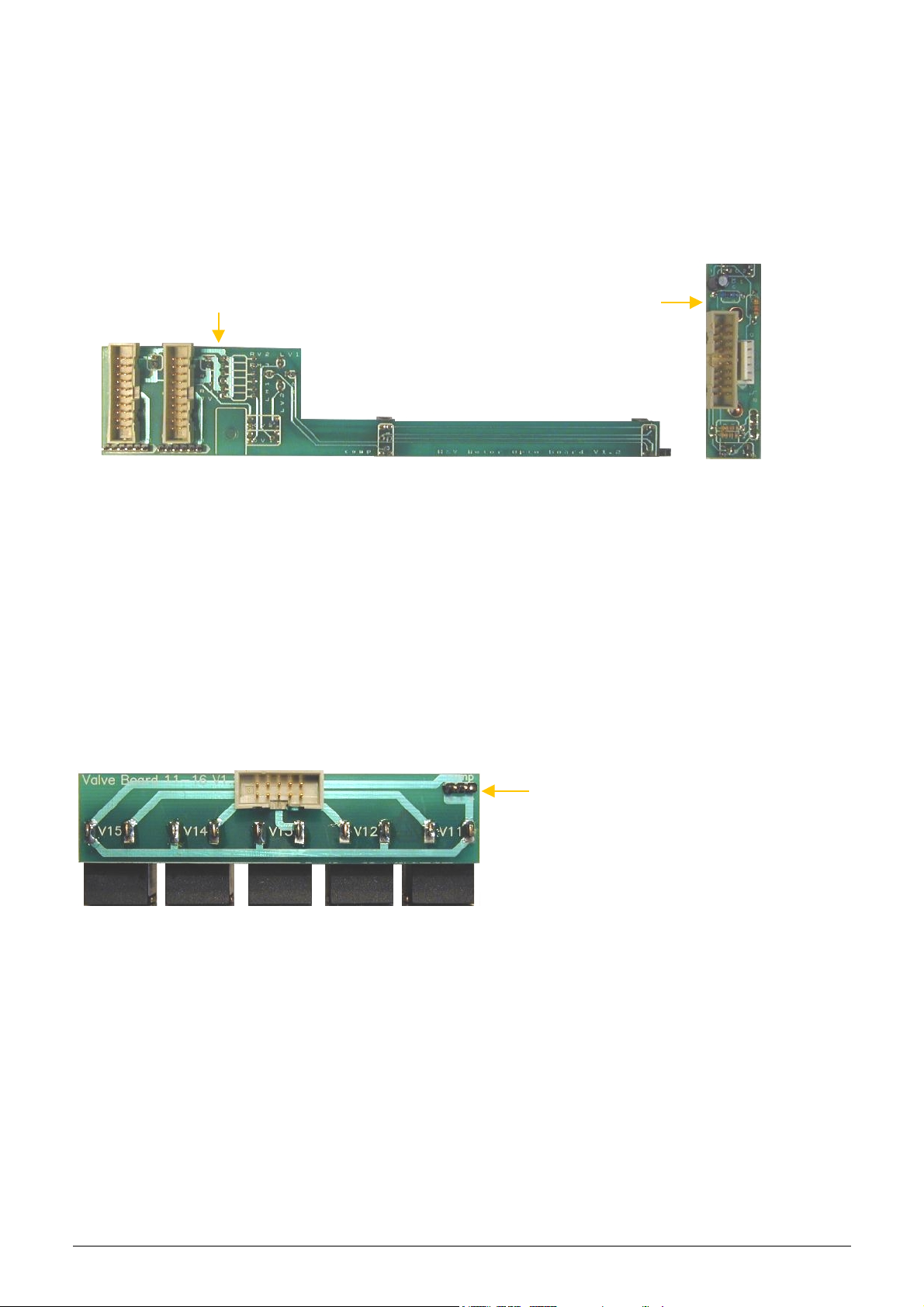
KH=H=K) 286AA6B)#J8JB)&A8J).J:B5-
There are three stepper motors in the system: Horizontal and Vertical motors, which make the movements of the
aspirating tip moving carriage, and Dilutor motor, which moves the three syringes (macro, lyse, micro). The
stepper motor opto boards make the connections between the motor controller PICs and motors, and have opto
switches for the motor’s end and home positions. The actual status of the stepper motor’s optos is indicated by
two LEDs on both stepper motor opto boards.
H&V motor opto board connects to the horizontal and vertical stepper motors and to the MPNIF card (through
HM and VM ribbon cables). On the other side of this board, there are four opto switches of the two stepper
motors positions (home and end for both) and its own indicator LEDs.
H&V motor opto board Dilutor motor opto board
Dilutor motor opto board contains the opto switches of the dilutor motor, which moves the syringes in the fluidic
system and the connection between the motor and the DM ribbon cable (from the MPNIF card). On the other
side of the board there are two opto switches (home and end switches) and their own indicator LEDs.
KH=H=L) S:+G6)@B4G6B).J:B5-
In the
!"#$%&"'()*/"2
there are three kinds of different valve driver boards:
! Valve board 1-5
! Valve board 6-10
! Valve board 11-15 & pump
In the
!"#$%&"'(
there are only two kinds of valve driver boards:
! Valve board 1-5
! Valve board 11-15 & pump
The Valve 11-15 driver board contains the
MO connection to the Pump unit.
The valve driver boards are connected to controller chips located on the MPNIF card through A, B and C ribbon
cables. (In
!"#$%&"'(
there is no B cable). These boards control the valves in 5-valve sets.
14/77 Service Manual HUMACOUNT & HUMACOUNT PLUS
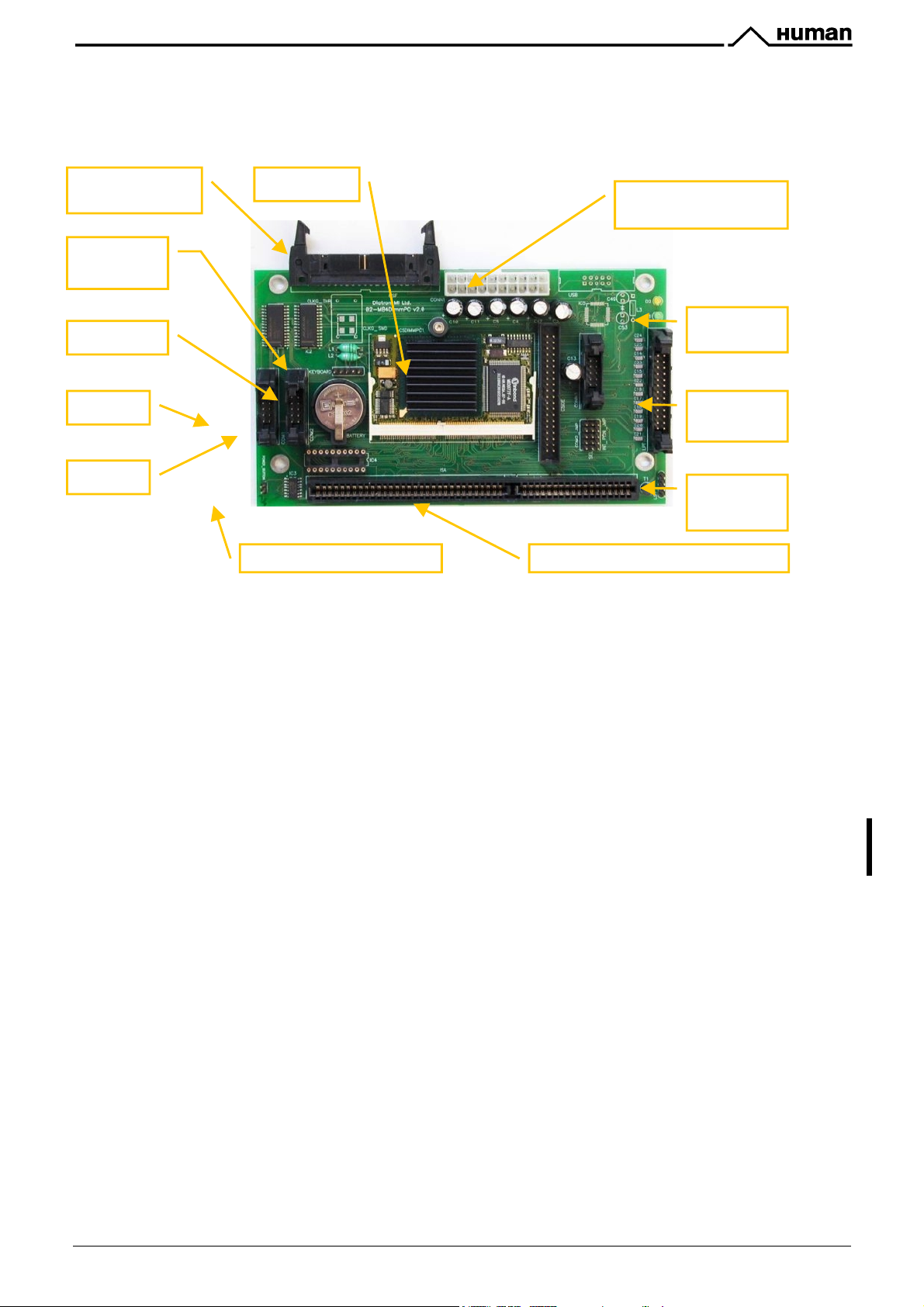
KH=H=T) #:4;).J:B5)]#.T^
The analyzer works with a main board called
detailed in Chapter 6.
. Required settings of MB4 board and BIOS setup values are
#.T
Floppy
Connector
DimmPC
ATX Power Supply
Connector
Keyboard
Connector
Standby
Li battery
COM1
Printer
Connector
COM2
Speaker
Connector
#.T)9J:B5
contains the necessary connectors for the different resources, and an ISA slot for the MPNIF board.
There is a 3V Li-battery to feed Real-Time Clock and Calendar (RTCC) chip during power down.
1+JAAE)54-<)5B4G6
is connected to the MB4 with a ribbon cable. The required configuration of the floppy disk
drive (boot sequence) can be set in the Boot priority section of the BIOS settings.
S456J):5:A86B
(MDA: Monochrome Display Adapter) and
G456J) C6CJBE
are placed on the MPNIF card. In
MDA mode the instrument displays the text monitor output on the LCD.
Two LEDs are indicating the state of power on MB4 main board:
1. Green LED is on, if external power is present (stand-by mode),
2. Yellow LED is on, if power is turned on.
>8N)G&'"%1#O%'%V3%"2)8'D#N%"H'#"'30"2'#77'D#N%"'&N53$E'#2'3E%'D#N%"'&0DD8G'57'G#0'"%1#O%
#"'"%D8)$%'$#1D#2%23&'+%KFK'C511!,H'.!:6;H'.(Y'1)52'I#)"*H'%3$K
KH=H=[) @4CC*%)#J5,+6
The MB4 board incorporates a credit-card sized PC, named
@4CC*%c
133MHz Pentium-class core, with 32Mbytes on-board RAM, and 32Mbytes on-board SanDisk. This is the HDD
(hard disk drive) of the analyzer, so instrument software with all user settings, calibration, database, etc. is
stored on the DimmPC.
>#7!88):?#!;#%@2#A&-.2#B-&6#'=#C'"%&'"#18<2..2.#B'.+*2;#D8<E
Service Manual HUMACOUNT & HUMACOUNT PLUS 15/77
. The processor on the DimmPC is a
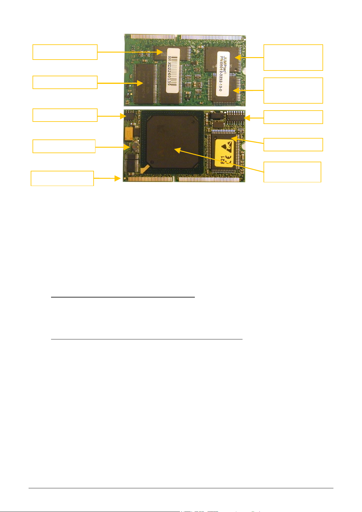
Flash
Hard Disk
(SanDisk)
32 Mbytes RAM
SanDisk
controller
CMOS
On-board
Real-timeclock
Super I/O
AMD Elan
Edgeconnector
KH=H=_)
KH=H=V) 2N48D34;M)*JN6B)2,AA+E
The analyzer works with a standard, 200 or 230VA ATX type PC switching power supply. The power supply has
its own internal fuse and a built in fan. The most frequent problem is the malfunction of the fan, so check and
clean it regularly. The power supply has a temperature sensor, which can detect overheating and shut down the
power.
KH=H=U) 1+JAAE)@4-<)@B4G6
The built in Floppy Disk Drive makes possible to save data on floppy disks, and to install (or upgrade) the
software.
I normal case (and for SW upgrade), the boot device priority should be Hard Drive then Floppy drive in BIOS
Setup. In this case, the analyzer starts up from SanDisk.
Boot Device Priority submenu – for Normal operation:
+ Hard Drive
+ Removable Devices
If you need to boot from Floppy disk, set up the following boot order. In this case it is possible to boot from an
external floppy disk, containing bootable code (e.g. MS-DOS). You can refer to the floppy disk as A:, SanDisk
will be C:.
Boot Device Priority submenu – for booting from a bootable floppy disk:
+ Removable Devices
+ Hard Drive
SC520
KH=H=`) *:B:++6+):;5)"2.)*B4;86B)*JB8-
The “Printer” port located on the rear panel is for external printers with parallel port.
The USB port is an option. If DimmPC is equipped with USB module, and at least SW V3.0 is installed the
analyzer supports USB printer connection.
KH=HKW) 26B4:+)*JB8
The Serial port is a standard RS232 V24 port with the standard pin-out. COM1 – marked “Serial” can be used is
useful for communication with a host computer.
16/77 Service Manual HUMACOUNT & HUMACOUNT PLUS
KHK) #:4;)C6D3:;4D):;5)7+,454D)A:B8-)J7)836)$;:+EO6B
!"#$%&"'()*/"2F!"#$%&"'(
1. Dilutor
2. H&V moving unit
3. Volume meter tube (xVM) – only for
4. Pump
5. Aspirating tip
6. Chamber(sc)
7. Valves (1-5, 6-10c, 11-15)
8. Washing head
9. Puffer reservoir
10. Tubing
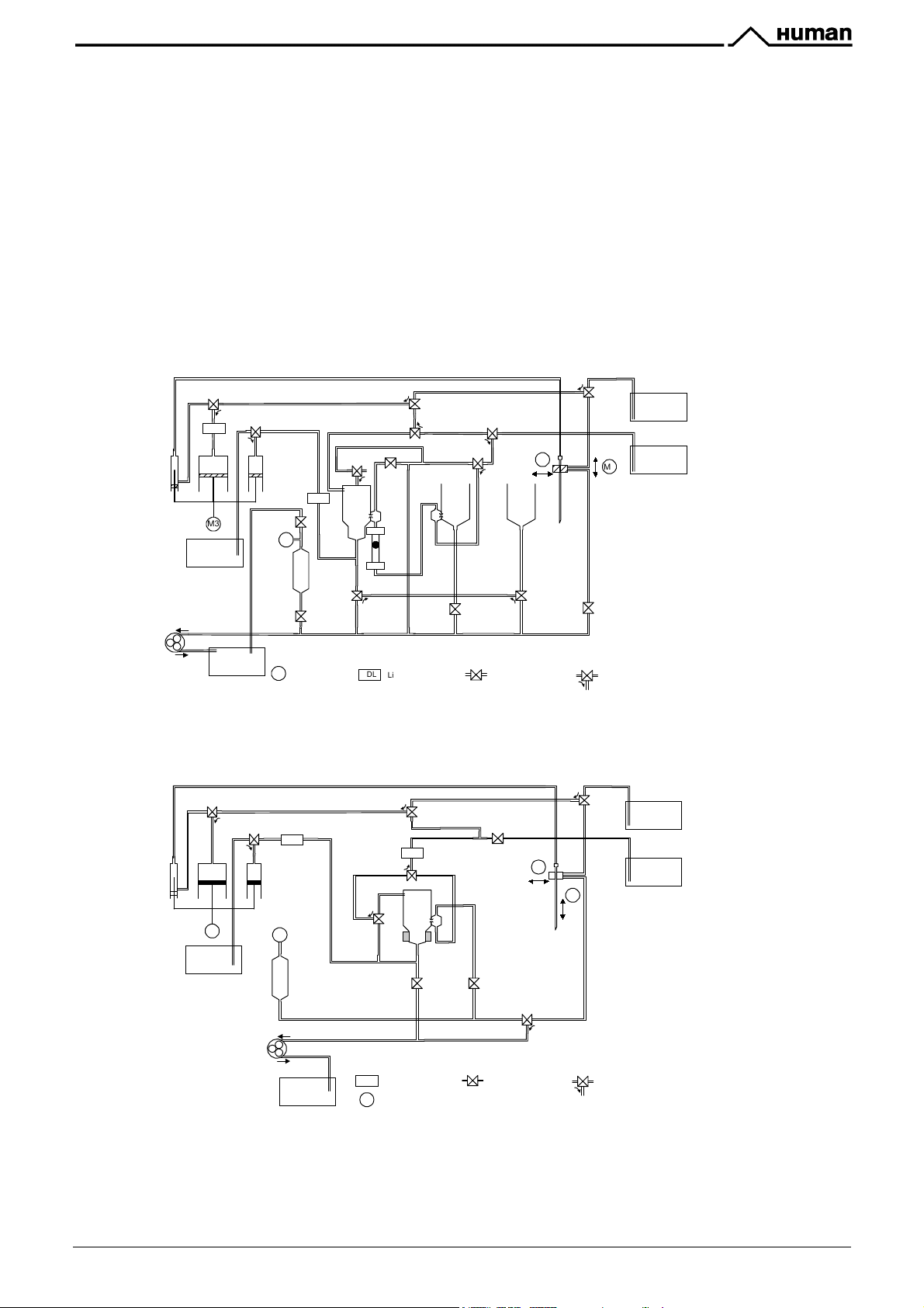
S=L)@4+'665+6
1
2
3
S=T)/E-6d9D
1
2
3
Lyse
S=[)*,776B$4B
Pressure
Meter
Micro Macro
Dil
LDL
M3
LYSE
Hematology Analyzers consist of the following mechanic and fluidic parts:
!"#$%&"'()*/"2
12
3
S=K)@4+1+J:8
3
2
1
S=W)@4+d9D
SV)1+J:8"A
SU)$-Ad9D
1
2
3
LDL
WBC
*
HGB
xV
M
SL)1+J:8@JN;
3
RBC
S`)%+6:;6B
12
3
12
M1
Hor Ver
MIX
S==)@4+d:-3
12
3
DILUENT
CLEANER
M2
Pump
Micro Macro
Dil
WASTE
S=L)@4+'665+6
12
3
M3
LYSE
2
Puffer
Reservoir
Waste Full Sensor
ST)@B:4;d9D
S[)*,776B
M1
Stepper Motor 2-way Valve
3
1
LDL
Liquid Detector
<=.>,-=:?'!@=A
<=.>,-=:?
1
3
S=K)@4+%3:C96B
S=T)/E-6d9D
1
2
3
Lyse
Pump
LDL
Lyse
Sensor
*
Pressure
Meter
Puffer
Reservoir
Diluent & Cleaner
Sensor
SL).,99+6
2
LDD
3
S=[)@4+$A6B8,B6
2
1
1
3
2
HGB
RBC/WBC
3
S=)@B:4;#4e
12
Closed = Off
Open = On
S_)@B:4;d:-3
SK)@B:4;?9D
4*+!.!3#F3@28-%!3;
4*+!.!3#F3@28-%!3;
S==)@4+d:-3
S[)%+6:;6B
M1
Hor
M2
Ver
SK)@B:4;$A6B8,B6S=)@B:4;%3:C96B
1
2
3
ST)@B:4;*,776B
12
1
3
2
3
3-way
Valve
1-3 = Off
2-3 = On
DILUENT
CLEANER
12
WASTE
LDx
M1
Liquid Detector
Stepper Motor
2-way Valve
Closed = Off
Open = On
3
3-way
Valve
1-3 = Off
2-3 = On
Service Manual HUMACOUNT & HUMACOUNT PLUS 17/77
KHKH=) $-A4B:84;M)84A
The aspirating tip is assembled in the H&V moving unit and it makes the sample aspirations. The right setting of
the aspirating tip is necessary and very important (see Chapter Adjustments).
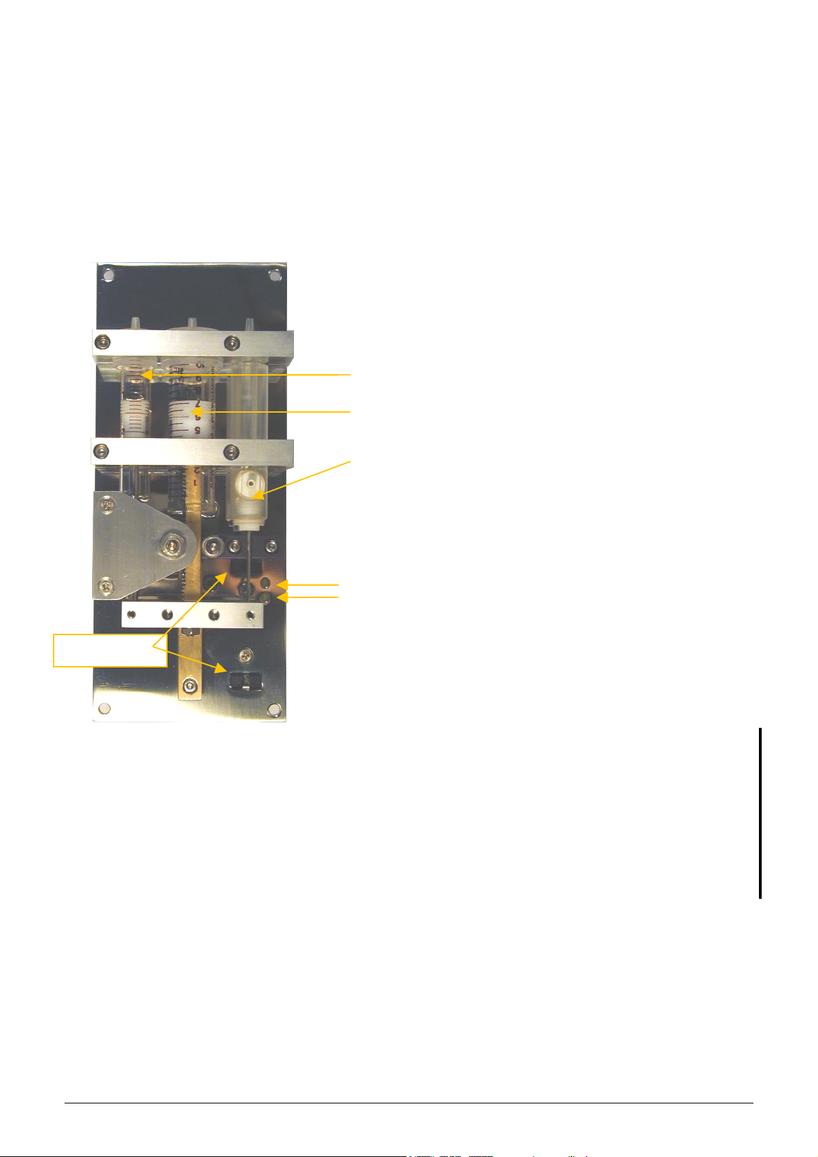
KHKHK) @4+,8JB
This unit is the same for both instruments (
stepper motor, the dilutor motor opto board, three syringes and the piston rods with special transmission. The
dilutor motor opto board is on the other side of this unit.
The picture below shows the
syringes.
!"#$%&"'() */"2F!"#$%&"'(
!"#$%&"'() */"2
Lyse syringe
Macro syringe
Micro syringe
Control lights
(LEDs) for
chackin the
state of opto
switches
and
!"#$%&"'(
dilutor module with the three separated
The dilutor block is operated by a stepper
motor, which is connected to the motor opto
board. The motor opto board has home &
end position opto switches. The optical
home/end position switches are operated by
a small tag fixed on the moving part. The
principle is the interruption of infra-red light
emitted by the diode of the sensor. The
control lights (LEDs) are showing the actual
state of the sensors: if the light is on, the
dilutor moving part reached the
corresponding sensor.
!"#$%&"'() */"2F!"#$%&"'(
module works with separated syringes (glass
for Macro and Lyse; plexiglass for Micro).
Macro syringe is for diluent reagent, Lyse
syringe is for lyse reagent, and the Micro
syringe is for precision sampling during
measurement.
) and includes the dilutor
dilutor
Opto switches
.)523%2)2$%'&E#08*'I%'D"#O5*%*'3#'3E%'D5&3#2'35D&H'IG')DD8G52F'2%03")8'&585$#2'F"%)&%'3#'3E%
$#FF%*'%2*'#7'3E%'.)$"#')2*'@G&%'D5&3#2&H'I%3N%%2' 3E%' &G"52F%')2*'3E%' 35D'53&%87K' ?E5&'N588
%2&0"%'#D35101'&%)852F')2*'8#2F%"'857%351%'#7'D5&3#2'35D&K
J"%)&52F' #7' 3E%' $#FF%*' 3")2&15&&5#2' D)"3&' +$#FNE%%8' )2*' $#FF%*' I)"/' &E#08*' I%' *#2%
"%F08)"8G'0&52F'1)$E52%'F"%)&%K
63'5&'"%$#11%2*%*'3#'$E%$S')2*'"%D%)3'F"%)&52F'#7'D5&3#2'35D&H')2*'3")2&15&&5#2'F%)"'%O%"G
G%)"H'#"')73%"'ZQQQQ'1%)&0"%1%23&K
18/77 Service Manual HUMACOUNT & HUMACOUNT PLUS
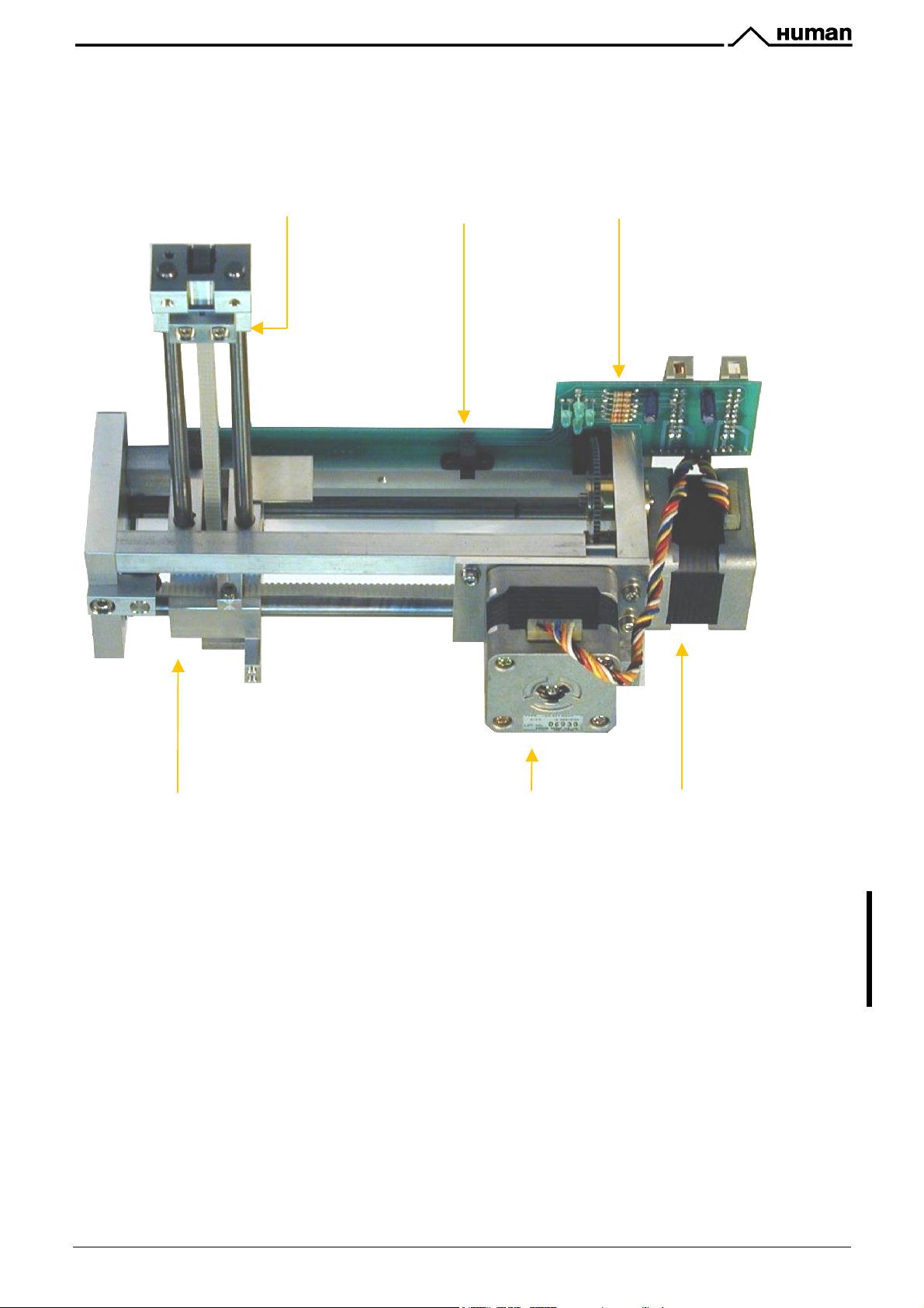
KHKHL) !\S)CJG4;M),;48)]fg^
This unit is the same for both instruments (
Horizontal and Vertical stepper motors, H&V motor opto board, opto wheel and the special mounting.
This moving unit moves the aspirating tip holding carriage and in the assembled analyzer it includes the
aspirating tip and the washing head.
Aspirating tip holder Home opto switch H&V motor opto board
!"#$%&"'() */"2
and
!"#$%&"'(
) and it contains the
Washing head housing Horizontal motor Vertical motor
The Vertical motor works with a special opto wheel for detecting home & end positions. See the adjustment
section of this manual to place this wheel to the proper position.
J"%)&52F'#7'3E%'E#"5T#23)8BO%"35$)8'F05*52F'"#*&'&E#08*'I%'*#2%'"%F08)"8G'0&52F'[!E#3#"0I\H
)'!?;]UI)&%*'3E52'80I"5$)23K
63'5&'"%$#11%2*%*'3#'$E%$S')2*'"%D%)3'F"%)&52F'#7'F05*52F'"#*&'%O%"G'G%)"H'#"')73%"'ZQQQQ
1%)&0"%1%23&K
Service Manual HUMACOUNT & HUMACOUNT PLUS 19/77

KHKHT) SJ+,C6)#686B)(,96)]eS#^)h)!"#$%&"'()*/"2)J;+E
The volume meter tube (xVM) is mounted on the volume opto board (see photo).
The tube contains a float, which is moved up by diluent flow
before counting.
Volume Meter tube
Float
During counting, first it comes down, the measurement is
started when the top LED goes off, and the movement of the
float is proportional to the volume of WBC dilution measured.
Counting stops when bottom LED goes on.
RBC counting is performed when the float goes upwards (none
of the LEDs are on).
?E%')""#N'#2'3E%' 30I%'10&3'D#523' 0DN)"*&'NE%2
"%D8)$52F'30I%K
C#'2#3'15V'0D'3E%'78#)3'*5"%$35#2'*0"52F'$8%)252F'#7'3E%'30I%H'I%$)0&%'3E%'$E)17%"52F'5&'2#3
&G11%3"5$)8H')2*'3E%'78#)3'1)G'I8#$S'3E%'30I%K'?E%'8#2FH'&1)88')2F8%'$E)17%"'10&3'7)$%'3#
3E%'I#33#1'#7'3E%'30I%K
KHKH[) *6B4-8:+84D)*,CA
The pump generates the regulated vacuum and drains the fluidic system. The pump is connected to the Valve
11-15 driver board (MO connection) and the control chip located on the MPNIF card, which drives this unit. The
pump is operated from 12Vdc.
If the tube of the peristaltic pump becomes worn, it can be broken, causing Pressure error.
63'5&'"%$#11%2*%*'3#'$E%$S'3E%'&3)3%'#7'3E%'30I%H')2*'"%D8)$%'53'%O%"G'^'G%)"&H'#"')73%"'^Q'QQQ
1%)&0"%1%23&K
>8N)G&'"%D8)$%'3E%'D%"5&3)835$'D01D'30I%'3#'3E%'&)1%'!E)".%*_'3GD%H'N53E'3E%'&)1%'8%2F3EK
For servicing the tube of the pump, open the peristaltic pump from its top (see picture) and remove the tube
together with the white plastic side wall (see picture):
In case of damaged tubes, it can be replaced by a new one by opening the two metal locks located at the two
ends of the tube (see picture).
20/77 Service Manual HUMACOUNT & HUMACOUNT PLUS
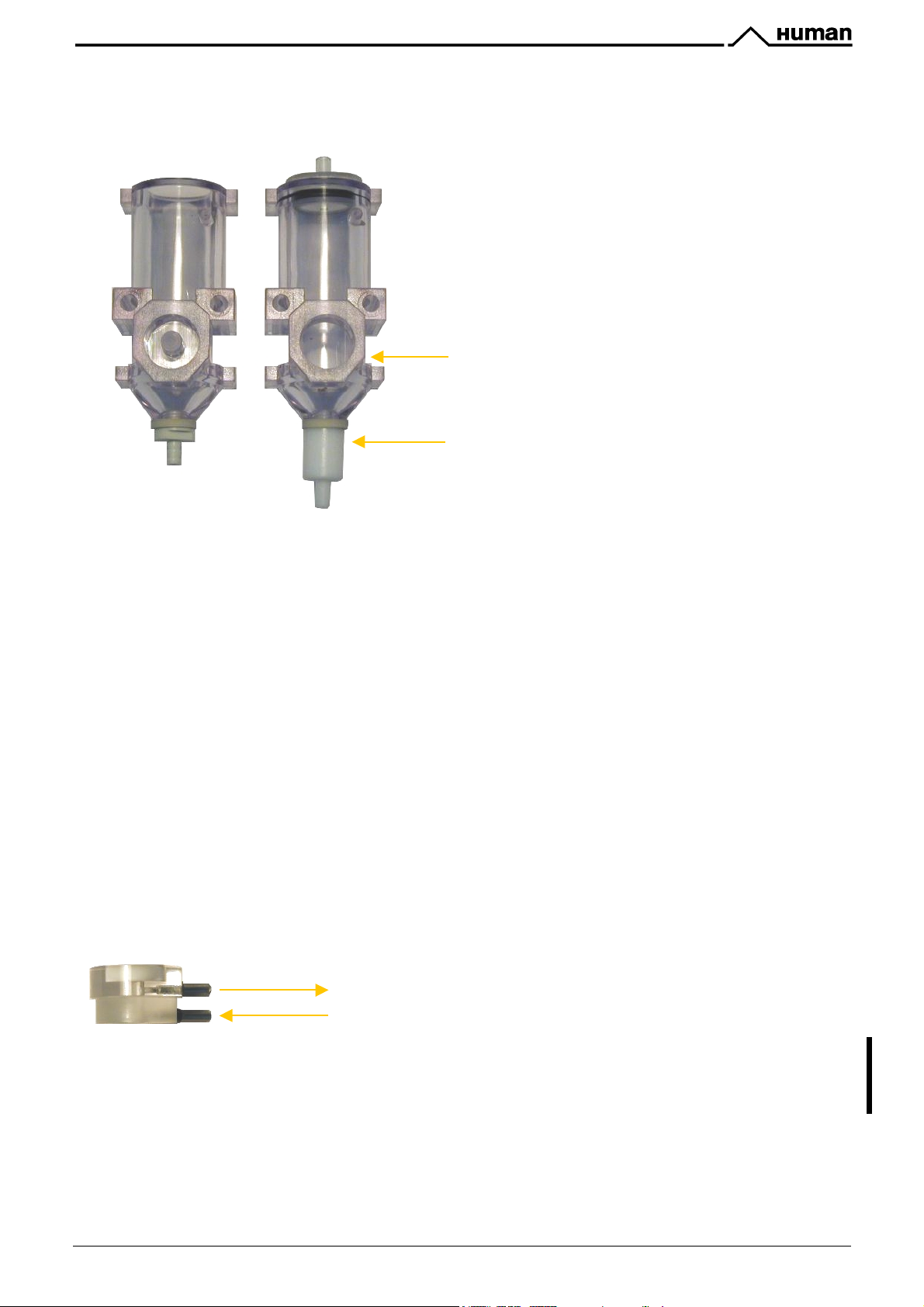
KHKH_) %3:C96B]-c^
In the
!"#$%&"'() */"2
there are three different chambers made of polycarbon. The MIX chamber is for the
first sample dilution. The RBC and the WBC chambers are mounted with the cell counter probes.
The chamber on the left is an
!"#$%&"'()*/"2
MIX
chamber, it is closed from the front and it is open at the
top.
The chamber on the right is an
!"#$%&"'() */"2
WBC chamber with the hole in the front for the
cellcounter probe. It is closed at the top and it has the
special WBC long PTFE draining connector.
Place for cellcounter probe
Long PTFE draining connector
In the
!"#$%&"'(
same as the WBC chamber in the
there is only one chamber for diluting and measuring the blood cells. This chamber is the
!"#$%&"'()*/"2
with the long draining connector but it is open at the top
– and it has an extender cap on it.
It is extremely important for both instruments that these chambers should have no damage or crack because it
could cause erroneous measurements (noise).
KHKHV) S:+G6-)]=P[R)_P=WcR)==P=[^
There are two kind of pneumatic valves in the system:
! 2-way Valve
! 3-way Valve
Valves are assembled in a unit of five on the valve blocks.
!"#$%&"'()*/"2
contains 3 of these boards (15 valves),
!"#$%&"'(
has only 2 valve blocks (10 valves).
KHKHU) d:-34;M)36:5
Washing head is located at the bottom of the H&V moving unit and it is for cleaning the outer surface of the
aspirating tip. This washing process is made by diluent reagent and the fluid is drained by the pump. The arrows
on the picture show the direction of diluent flow.
Draining by the pump
Diluent reagent
63'5&'"%$#11%2*%*'3#'$E%$S'3E%'&3)3%'#7'3E%'N)&E52F'E%)*')3'"%F08)"'&%"O5$%'O5&53&K
,8%)2'#"'"%D8)$%'53'G%)"8GH'#"')73%"'ZQ'QQQ'1%)&0"%1%23&K
Service Manual HUMACOUNT & HUMACOUNT PLUS 21/77

KHKH`) *,776B)B6-6BGJ4B
The puffer reservoir insures the stable vacuum during the measuring process.
!"#$%&"'(
on the assembled analyzers section of this manual.
KHKH=W) (,96-
The fluidic system contains tubes, which have different diameters and lengths and also made by different
materials.
Reagent paths requiring perfect sealing are made of Tygon tubing, the draining circuit is made of silicon.
The Tubing Schematics Section contains the parameters of the tubes (length & diameter).
puffer reservoirs
made by glass but in
:B6
54776B6;8
sizes. The figures of these units are shown
!"#$%&"'() */"2
and
63'5&'"%$#11%2*%*'3#'$E%$S'3E%'&3)3%'#7'3E%' 30I52F'`'%&D%$5)88G'8G&%'D)3E'`'"%F08)"8GH'*0"52F
&%"O5$%'O5&53&K
a02')'$#1D8%3%'I8%)$E52F'$G$8%H'$E%$S'#"'"%D8)$%'30I52F')2*'753352F&'G%)"8GH'#"')73%"
ZQ'QQQ'1%)&0"%1%23&K
22/77 Service Manual HUMACOUNT & HUMACOUNT PLUS
KHL) $--6C9+65)$;:+EO6B-
This section includes the photos of the assembled analyzers. There are two main parts for both instruments:
! The electronic block located on the left side
! The mechanic and fluidic block located on the right side and it is assembled to a stainless steal assembly
plate, which makes also the separation from the electronic block
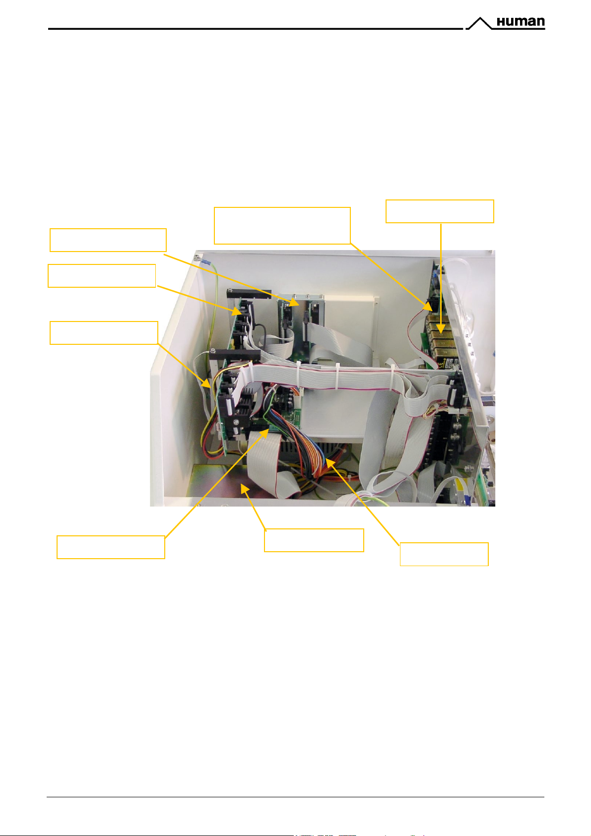
KHLH=) !"#$%&"'()*/"2)0+6D8BJ;4D).+JD<
This block contains the main electronic parts of
plate.
!"#$%&"'() */"2
, the cables and the main board holder
Interface connectors
MPNIF Card
IDEPROM Board
KHLHK)
Pressure and Reagent
Sensor Board
Valve Block III.
Main Board (MB4)
Service Manual HUMACOUNT & HUMACOUNT PLUS 23/77
Floppy disk drive
Power Supply
 Loading...