

Human HumaCount 30TS, HumaCount 60TS Service manual
HumaCount 30TS and 60
|
Service Manual
TS
16420/302

REVISION LIST OF THE MANUAL
Rev. /DATE REVISION DESCRIPTION
01/2010-09 First edition
SYSTEM VERSION
HumaCount 60TS and HumaCount 30TSwith software version 1.2 .
COPYRIGHT
Copyright 2010, Human GmbH, Wiesbaden, Germany. All rights reserved.
No part of this documentation may be reproduced in any form, nor processed, copied or
distributed by means of electronic systems, without prior permission of Human GmbH in
writing. Since all precautionary measures were taken into account in producing these operating
instructions, the manufacturer accepts no responsibility for any errors or omissions. This
includes any liability for damage that could arise from possible incorrect operation based on this
information. Subject to changes without notice as result of technical development.
SERVICE UND SUPPORT


CONTENTS
TABLE OF CONTENTS
1 SAFETY INSTRUCTIONS
1.1 INTRODUCTION 5
1.2 USER WARRANTY 5
1.3 INTENDED USE OF THE INSTRUMENT 6
1.4 GENERAL SAFETY WARNINGS 6
1.5 DISPOSAL MANAGEMENT CONCEPT 7
1.6 INSTRUMENT DISINFECTION 7
1.7 BIOHAZARD WARNING 8
2 INTRODUCTION 11
2.1 NAME AND SERIAL NUMBER 11
2.2 INTEGRATED SOFTWARE 11
3 FUNCTIONAL DESCRIPTION 13
3.1 MAIN ELECTRONIC PARTS OF THE ANALYZERS 13
3.1.1 Counting chamber with electrodes and measuring aperture 15
3.1.2 HGB Measuring Head 16
3.1.3 Cell Counter Amplifier Board – HC30TS 16
3.1.4 Cell Counter Amplifier Board – HC60TS 17
3.1.5 MAIN CPU Board 19
3.1.6 Dimm-PC* Module 22
3.1.7 Opto sensors 22
3.1.8 Valve boards 23
3.1.9 TFT Display and START button Board 23
3.1.10 External Power Supply 24
5
4 MAIN MECHANIC AND FLUIDIC PARTS 25
4.1 SINGLE PARTS 26
4.1.1 Sample/Horizontal and Vertical motors 26
4.1.2 Sampling needle 27
4.1.3 Needle washing head 27
4.1.4 Puffer reservoir 27
4.1.5 Dilutor block – HC30TS 28
4.1.6 Dilutor block – HC60TS 29
4.1.7 Measuring block (HC30TS) 30
4.1.8 Measuring block (HC60TS) 30
4.1.9 Pump 31

4.2 ASSEMBLED ANALYZER 31
4.2.1 Front Panel 31
4.2.2 Side Panel 32
4.2.3 Rear Panel (HC30TS) 32
4.2.4 Construction Front 33
4.2.5 Construction Side 33
5 OPERATION OF THE FLUIDIC SYSTEM 35
5.1 INITIALIZATION OF THE FLUIDIC SYSTEM 35
5.2 OPERATION OF THE FLUIDIC SYSTEM IN HUMACOUNT 30 TS 36
5.2.1 Flow diagram of measurement 36
5.2.2 Sampling process 38
5.2.3 Needle washing process 39
5.2.4 Diluting process 40
5.2.5 Lysing process 41
5.2.6 Counting process 42
5.2.7 Chamber draining process 43
5.2.8 Shutdown process 43
5.3 OPERATION OF THE FLUIDIC SYSTEM IN HC60TS 44
5.3.1 Sampling process 45
5.3.2 Diluting process 46
5.3.3 Lysing process 47
5.3.4 Counting process 48
5.3.5 Chamber draining process 49
5.3.6 Cleaning process 50
5.3.7 Shutdown process 50
6 ADJUSTMENTS 51
6.1 COMMON ADJUSTMENTS 51
6.1.1 Vertical movement, setting timing belt tension 51
6.1.2 Vertical opto sensor and needle settings 51
6.1.3 Setting the needle shaft 52
6.1.4 Setting the position of the chambers 53
6.2 HC30TS SPECIFIC ADJUSTMENTS 54
6.2.1 Setting the dilutor mechanics 54
6.2.2 Setting the horizontal movement 54
6.3 HC60TS SPECIFIC ADJUSTMENTS 55
6.3.1 Setting the dilutor mechanics 55
6.3.2 Setting the horizontal movement 55

CONTENTS
6.4 SERVICE CALIBRATION 56
6.5 SETTING RBC AMPLIFIER GAIN 57
6.6 SETTING WBC AMPLIFIER GAIN 58
7 CHECKIG THE PROPER OPERATION 59
7.1 SELF TEST 59
7.1.1 Self Test Screens 59
7.1.2 Normal range of Self Test parameters 60
7.1.3 Troubleshooting Guide for Self test 60
7.2 SERVICE MENU 61
7.2.1 Entering to Service Menu 61
7.2.2 Troubleshooting 62
7.2.3 Stress 63
7.2.4 Needle position check 64
7.2.5 Log in as SERVICE User 64
8 SERVICE OPERATION 67
8.1 POSSIBLE CAUSES OF NOISE 67
8.1.1 Contaminated reagent 67
8.1.2 Bad earth grounding 67
8.1.3 External electrical noise 68
8.1.4 Internal noise sources 68
9 MAINTENANCE 71
9.1 WEEKLY USER MAINTENANCE 71
9.1.1 Cleaning needle washing head 71
9.2 PERIODIC MAINTENANCE BY SERVICE 72
9.2.1 Check Self test and Device statistics 72
9.2.2 Cleaning and Greasing Dilutor Block 72
9.2.3 Checking and Lubricating Dilutor Piston Tips 72
9.2.4 Checking and Replacing Washing Head 73
9.2.5 Bleaching of Fluidic System 73
10 APPENDICES 75
10.1 WARNING FLAGS 75
10.2 USB B CONNECTOR COMMUNICATION 76
10.2.1 Characters and basic structure 77
10.2.2 Details of the 3.1 protocol 77

10.3 CABLING DIAGRAM 80
10.4 TUBING SCHEMATICS 82
10.5 RECOMMENDED KIT OF TOOLS 84

SAFETY INSTRUCTIONS 5
1 SAFETY INSTRUCTIONS
1.1 Introduction
This manual is considered as a part of the instrument; it has to be at the
operator’s hand as well as at the maintenance operator’s availability. For
accurate installation, use and maintenance, please read the following
instructions carefully. In order to avoid instrument damage or personal
injury, carefully read the ”GENERAL SAFETY WARNINGS”, describing the suitable
operating procedures. In case of breakdowns or any troubles with the
instrument, apply to the local Technical Service.
1.2 User Warranty
HUMAN warrants that instruments sold by one of its authorised representatives shall be free of any defect in material or workmanship, provided that this
warranty shall apply only to defects which become apparent within one year
from the date of delivery of the new instrument to the purchaser.
The HUMAN representative shall replace or repair any defective item at no char-
ge, except for transportation expenses to the point of repair.
This warranty excludes the HUMAN representative from liability to replace
any item considered as expendable in the course of normal usage, e.g.: lamps,
valves, syringes, glassware, fuses, diskettes, tubing etc.
The HUMAN representative shall be relieved of any liability under this warranty
if the product is not used in accordance with the manufacturer‘s instructions,
altered in any way not specified by HUMAN, not regularly maintained, used with
equipment not approved by HUMAN or used for purposes for which it was not
designed.
HUMAN shall be relieved of any obligation under this warranty, unless a
completed installation / warranty registration form is received by HUMAN
within 15 days of installation of this product.
This warranty does not apply to damages incurred in shipment of goods. Any da-
mage so incurred shall be reported to the freight carrier for settlement or claim.
equipment not approved by Human or used for purposes for which it was not
designed.
Human shall be relieved of any obligation under this warranty, unless a completed installation / warranty registration form is received by Human within
15 days of installation of this product.

6
This warranty does not apply to damages incurred in shipment of goods. Any
damage so incurred shall be reported to the freight carrier for settlement or
claim.
1.3 Intended Use of the Instrument
[IVD]
The instrument is intended for in vitro diagnostic application by professional
users. It has to be used for the expected purposes and in perfect technical
conditions, by qualified personnel, in working conditions and maintenance
operations as described in this manual, according to the GENERAL SAFETY
WARNINGS. This manual contains instructions for professional qualified
operators.
TS
HumaCount 30
/ HumaCount 60TS hematology analyzers are fully automated cell counters for in vitro diagnostic use. The compact instruments were
developed for small clinics, point-of-cares, and hospitals.
TS
HumaCount 30
can process 30, HumaCount 60TS can process 60 samples
per hour and they are intended to determine the following 18 hematology
parameters from a 25μL whole blood sample:
- WBC - LYM - MON - GRA - LYM% - MON% - GRA% (three-part WBC
differential)
- HGB - RBC - HCT - MCV - RDW - MCH - MCHC
- PLT - MPV - PCT – PDW
HumaCount 30TS / 60TS | Service manual
1.4 General Safety Warnings
Use only chemical reagents and accessories specified and supplied by HUMAN and/or mentioned in this manual. Place the product so that it has proper
ventilation.
The instrument should be installed on a stationary flat working surface, free
from vibrations.
Do not operate in area with excessive dust.
Work at room temperature and humidity, according to the specifications listed
in this manual.
Do not operate this instrument with covers and panels removed.
Only use the power cord specified for this product, with the grounding
conductor of the power cord connected to earth ground.
Use only the fuse type and rating specified by the manufacturer for this instrument, use of fuses with improper ratings may pose electrical and fire hazards.
To avoid fire or shock hazard, observe all ratings and markings on the
instrument.

SAFETY INSTRUCTIONS 7
Do not power the instrument in potentially explosive environment or at risk of
fire.
Prior to cleaning and/or maintaining the instrument, switch off the instrument
and remove the power cord.
For cleaning use only materials specified in this manual, otherwise parts may
become damaged. It is recommended always to wear protective apparel and
eye protection while using this instrument. Respective warning symbols, if
appearing in this manual, should be carefully considered.
1.5 Disposal Management Concept
The currently valid local regulations governing disposal must be observed. It is in
the responsibility of the user to arrange proper disposal of the individual
components.
All parts which may comprise potentially infectious materials have to be
disinfected by suitable validated procedures (autoclaving, chemical treatment)
prior to disposal. Applicable local regulations for disposal have to be carefully
observed.
The instruments and electronic accessories (without batteries, power packs etc.)
must be disposed off according to the regulations for the disposal of electronic
components.
Batteries, power packs and similar power source have to be dismounted from
electric/electronic parts and disposed off in accordance with applicable local
regulations.
1.6 Instrument Disinfection
Analytical instruments for in vitro diagnostic involve the handling of human
samples and controls which should be considered at least potentially infectious.
Therefore every part and accessory of the respective instrument which may have
come into contact with such samples must equally be considered as potentially
infectious.
Before doing any servicing on the instrument it is very important to
thoroughly disinfect all possibly contaminated parts. Before the instrument is
removed from the laboratory for disposal or servicing, it must be
decontaminated.
Decontamination should be performed by authorised well-trained personnel
only, observing all necessary safety precautions. Instruments to be returned
have to be accompanied by a decontamination certificate completed by the
responsible laboratory manager. If a decontamination certificate is not
8
supplied, the returning laboratory will be responsible for charges resulting from
non-acceptance of the instrument by the servicing centre, or from authority’s
interventions.
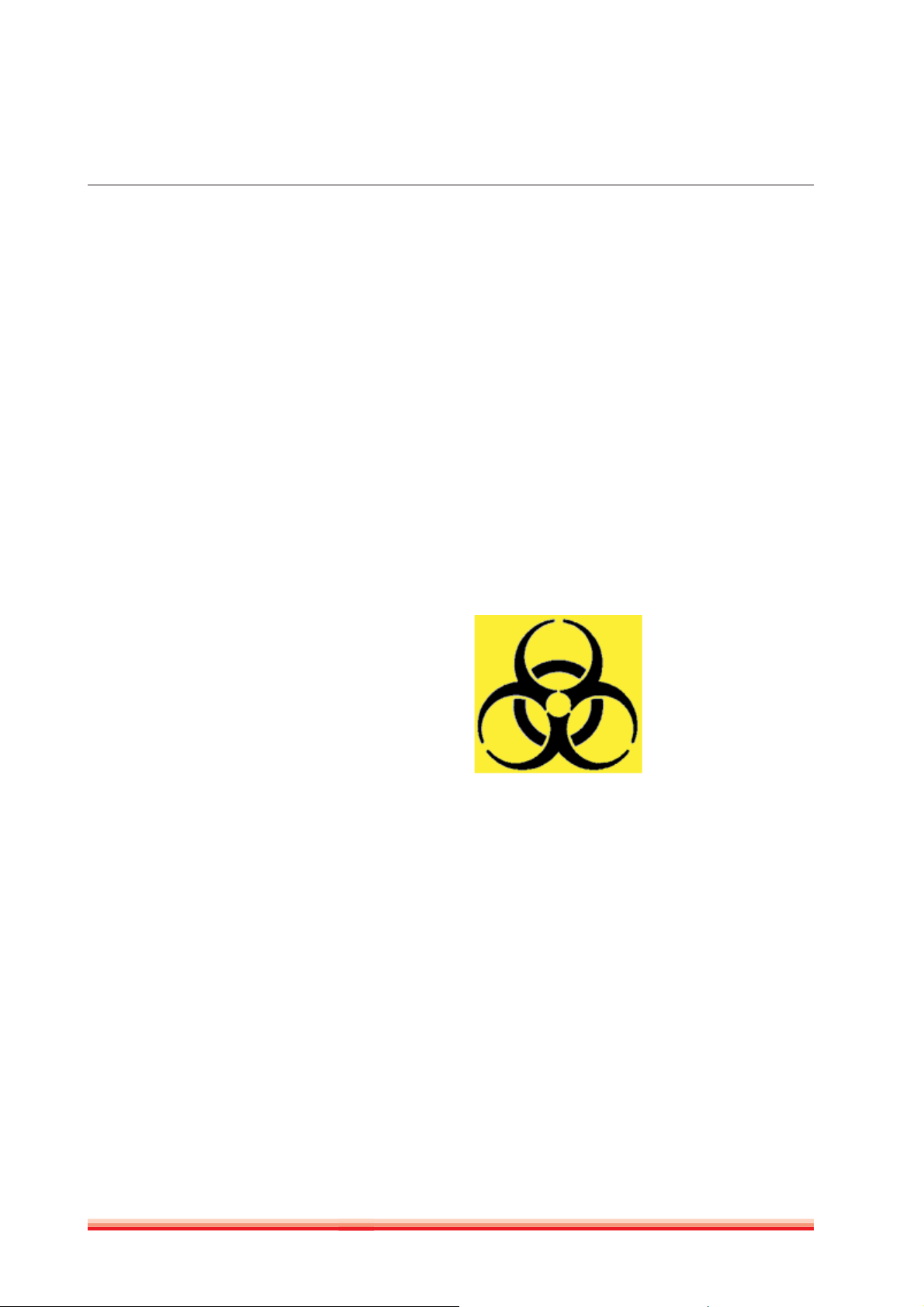
1.7 Biohazard warning
Analytical instruments for in vitro diagnostic application involve the handling
of human samples and controls which should be considered at least potentially
infectious.
Therefore every part and accessory of the respective instrument which may have
come into contact with such samples must equally be considered as potentially
infectious.
For safety reasons, we have labeled instruments with the „BIOHAZARD“
warning label below.
FIGURE 1
Biological Hazard
Symbol
HumaCount 30TS / 60TS | Service manual

SAFETY INSTRUCTIONS 9
Notes:

10
HumaCount 30TS / 60TS | Service manual

INTRODUCTION 11
2 INTRODUCTION
Since HumaCount 30TS and HumaCount 60TS have so much common
characteristics, we issue a common Service Manual covering both instruments.
Information herein applies for all instruments unless otherwise noted.
To be well up in the instruments, please read this manual carefully to have the
knowledge for servicing the instruments perfectly and avoid extra costs and
wasting precious time.
In this manual, we are using the following conventions:
HC30TS – stands for HumaCount 30
HC60TS – stands for HumaCount 60
This HumaCount 30TS / HumaCount 60TS Service Manual contains the functional
descriptions of all analyzers, operation of the fluidic systems, adjustments and
settings, and very important information for the service personnel about the
service operations and possible problems.
TS
TS
2.1 Name and serial number
Name: HumaCount 30TS / HumaCount 60TS Hematology Analyzer
Every instrument has its own serial number, which is printed
Serial No.:
on the rear panel label and it can be read out from Device Information or from the self test submenu. This identity number
is write-protected by HUMAN.
2.2 Integrated software
The integrated software controls the instrument operations, displays, stores,
recalls data, and allows the user to perform QC and calibration procedures and
modify the user settings. The software version number can be read out from the
Device Information or from the Self test submenu.
Every HC30TS / HC60TS software version is upgradeable (using an USB flash
drive) by the latest program developed by HUMAN, and it can be downloaded
from: http://www.human.de

12
HumaCount 30TS / 60TS | Service manual

FUNCTIONAL DESCRIPTION 13
3 FUNCTIONAL DESCRIPTION
3.1 Main electronic parts of the analyzers
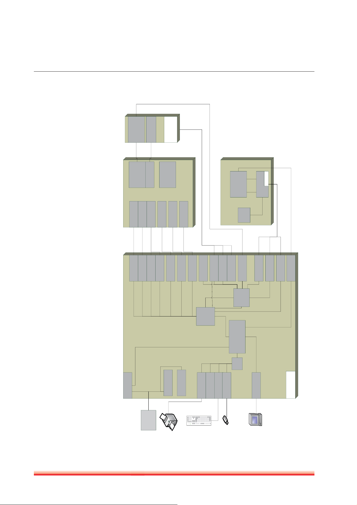
HC30TS / HC60TS contain the following electronic parts:
1. Counting chamber (2 pcs in HC60TS) with electrodes and measuring aperture
2. HGB Measuring Head
3. Cell Counter Amplifier Board
4. MAIN CPU Board with Dimm-PC and measurement processing unit, 4 motor controllers, valve & pneumatic
controller/driver, pump driver and power supply for internal printer (+7.5V) and digital circuitry (+5V, +3.3V)
5. DIMM-PC module
6. Motors with opto-boards of needle moving motor (H) and sample rotor/needle moving motor (V)
7. Dilutor block with opto-board for sampling, diluent, lyse and cleaner
8. Valve boards (set of 5 and max. 7)
9. Peristaltic Pump (2 pcs in HC60TS)
10. USB interface
11. Graphic LCD Display Module with touch-screen
12. Start Button Panel
13. Internal Printer
14
(HC30TS)
FIGURE 2
Block diagram
Amplifier Board
HGB int erface
Cell counter Amplifier
HC60TS)
(MIX/WBC in
Counting chamber
HGB measuring head
(HC60TS)
AJ-Meas v3.1
AJ5-Meas v1.0
Display
Assembly
RBC chamber
(in HC60TS only)
TFT modul
w/ touchscreen
320*240 (QVGA)
w/ LED backlight
BLTS v1.0
Sign Collection Board
Rotor motor
Motor driver 1
MAIN Board (CPU, Pneumatic and Power Board) Fluidic System
interface
Internal printer
HC60TS)
Motor driver 1
Dilutor motor( 2 in
Snap in optosensors
Motor driver 2
Motor driver 3
in HC60TS only)
Motor driver 4 (used
Pump
Valve block I_II
Pump driver
Valve drivers
Opto sensor inte rface
Digital power 5V
Digital power 3.3V
DIGIO
Measure control
Pressure sensor
FPGA
XCS30XL
USB A 1
USB A 3
USB A 2
Start
Status
button &
LED board
USB B
interface
Touchscreen
LCD backlight driver
To PIC ADC
DC/DC ±12V
HVB(50V, 150V)
PIC24
ȝController
DIMMPC
AMD Elan SC-520
USB
HUB
USB A 4
LCD driver
LEDs interface
Start Button, Status
ACS Main Board v2.1
HumaCount 30TS / 60TS | Service manual
Supply
12 VDC
external Power
External printer
USB stick
External keyboard
External PC
FUNCTIONAL DESCRIPTION 15
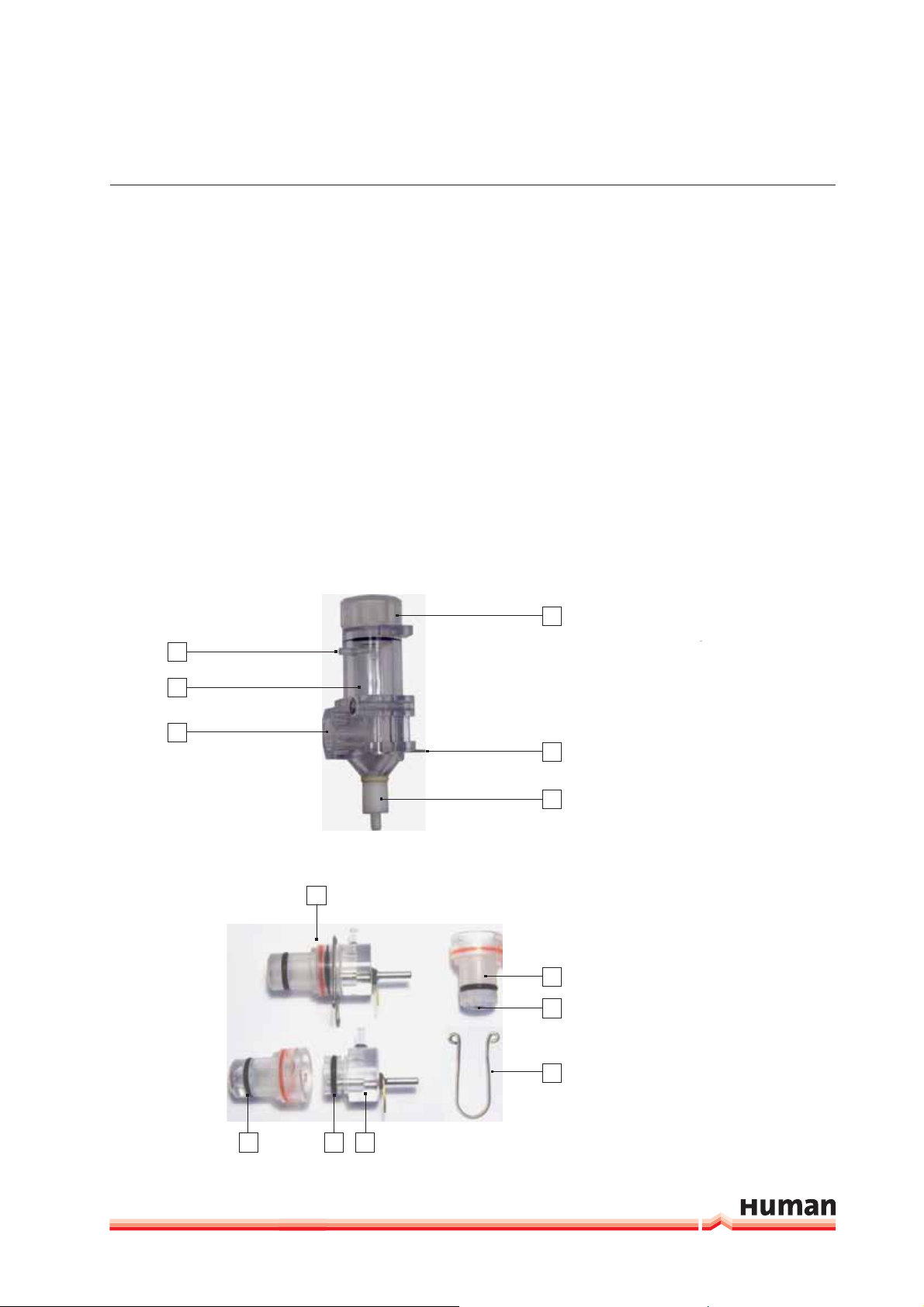
3.1.1 COUNTING CHAMBER WITH ELECTRODES AND MEASURING APERTURE
Impedance method is used for determination of volume and number of cells.
In this method a known volume of dilution is drawn through a small aperture.
Constant current is passed through the aperture from one side to the other.
When a cell passes through the aperture, it causes a change in resistance, which
generates a voltage pulse.
The amplitude of the voltage pulse is proportional to the ratio of cell volume
per aperture volume. This is used to determine the volume of cells. The number
TS
of cells can be obtained by counting the pulses. In the HC30
there is one
cell-counter probe: the aperture size is 70 μm and has a reference electrode
assembly and U-shaped metal fixing as it is shown in the figure below.
The aperture is made of ruby and it is molded into the end of the measuring tube.
TS
In the HC60
there are two separate chambers: one for counting RBC with an
aperture of 80 μm, and another for MIX/WBC/HGB with 100 μm aperture.
4
FIGURE 3
1
Measuring chamber
2
3
5
6
1
6
5
4
2 2
3
1 Washing inlet
2 Counting chamber
3 Opening for measuring tube
4 Chamber extender
5 Platinum electrode
6 Draining connection
FIGURE 4
Measuring tube
1 Complete measuring tube
2 O-rings
3 Reference electrode
4 U-shaped metal fixing
5 Aperture
6 Measuring tube with aper-
ture (70/80/100μm)
16
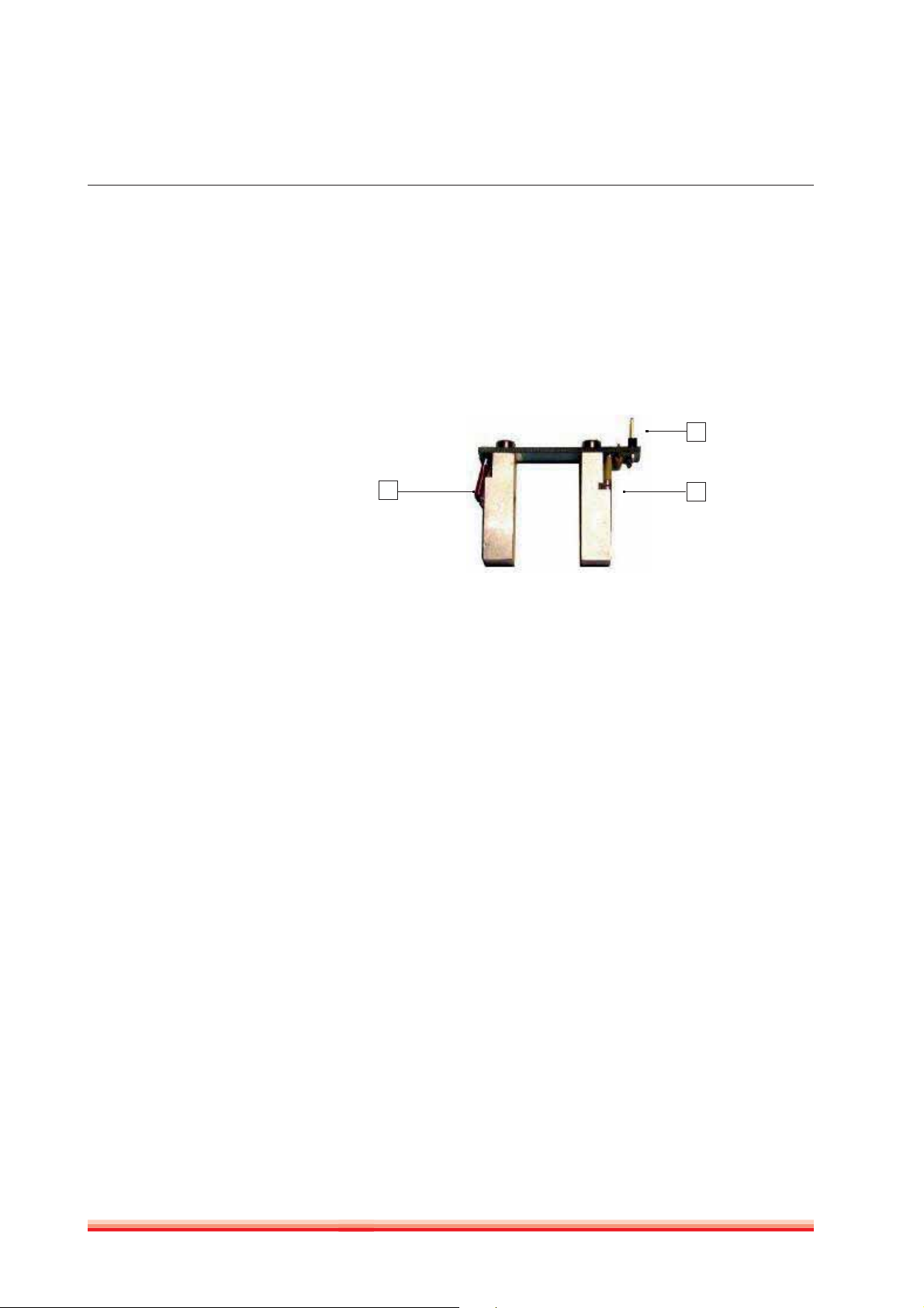
3.1.2 HGB MEASURING HEAD
Hemoglobin head is placed around one measuring chamber in all instruments.
It contains: light source (LED) at 540 nm wavelength and Photo
Detector (TSL235). The Photo Detector converts the light to frequency. The HGB
concentration is a logarithmic function of this frequency measured by the
FPGA circuit of the MAIN board.
FIGURE 5
HGB measuring head
1 LED
2 Connection to
the amplifier
3 TSL 235
Due to enhanced HGB tech-
nology, HC30TS / HC60TS is
!
less sensitive to incident light
changes. However, it is recom-
mended to keep side door closed
during measurements.
2
1
3
The analyzer performs enhanced hemoglobin measurement technology for HGB
measurement. The frequency output signal of TSL235 is counted by a digital
counter in the FPGA circuit.
This counter counts up while the LED is on and counts down while the LED
is off. The LED and direction of counting are switched with a 100 Hz signal.
This method provides “real time backlight correction”, which makes the HGB
measurement more precise in changing backlight environment situation as well.
There are two kinds of HGB measurement:
- Sample measurement (before RBC counting)
- Diluent/blank measurement (in WBC washing phase)
The HGB result is calculated from these measurements by:
HGB log (CNT
diluent light
/ CNT
sample light
)
HumaCount 30TS / 60TS | Service manual
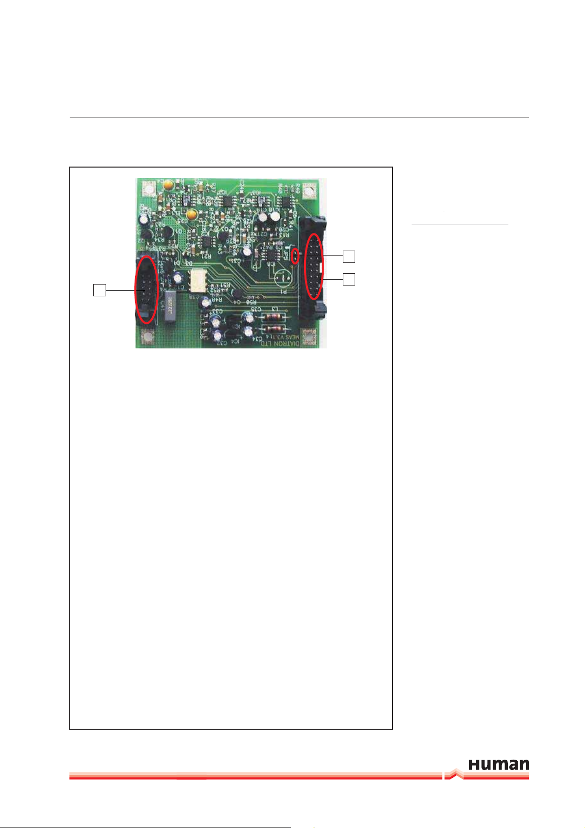
3.1.3 CELL COUNTER AMPLIFIER BOARD – HC30TS
Amplifier board includes its own voltage regulator, connection interfaces to
HGB head and to MAIN board. There is a current generator circuit on it, which
works from 50V measuring voltage (generated by MAIN) and the probe voltage
(DC) is amplified with a voltage follower (output: ELV). Nominal measuring
current is 870 μA.
Amplifier board includes one input connector for the chamber (measuring
electrode). There are two opto switches (U1, U3) to connect high voltage to the
probe with HSW signal and isolate the input of the amplifier. Test circuit makes
possible to generate test pulses (with TEST and PLS signals through FETs) for
checking the proper operation of the amplifier channel.
FUNCTIONAL DESCRIPTION 17
FIGURE 6
Cell counter amplifier board
2
3
1
Amplifier board includes a 3-stage main amplifier channel, which gains input
signal to the 0...3.3 V range (this is the input range of the A/D converter, which
is placed on the MAIN board). The RSW signal changes the gain (RBC, WBC) in
the feedback of the second amplifier stage with U2 (MAX319) analog switch.
Amplifier gain and offset are adjusted by software.
DHON signal switches on the LED and the MVON signal – which is active during
counting – switches off the Photo Detector in the HGB head, to prevent noise
generated by the HGB detector.
The other side of the amplifier board contains special connectors for the cham-
ber and the HGB head (JP4).
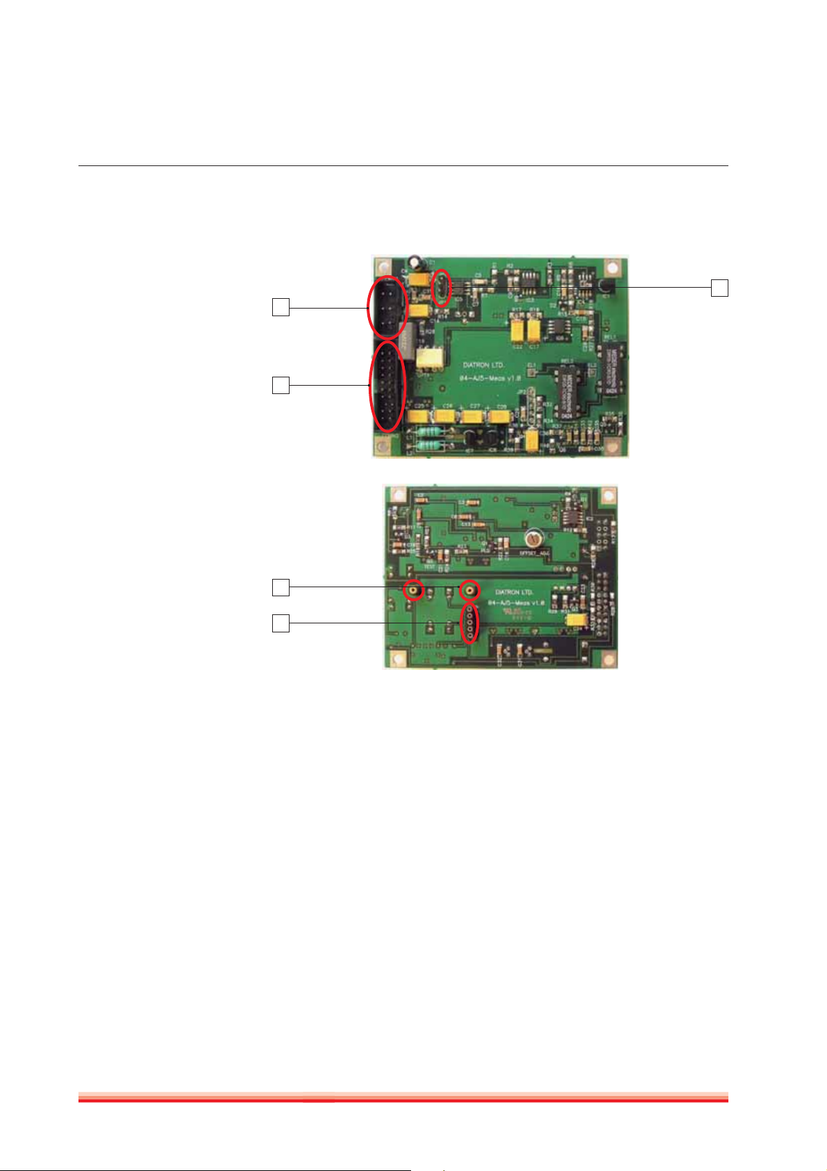
3.1.4 CELL COUNTER AMPLIFIER BOARD – HC60TS
Amplifier board includes its own voltage regulators, connection interfaces to
HGB head, to chamber electrodes, high voltage and DIGIO connector to Main
board. There is a current generator circuit on this board, which works from
50V measuring voltage (generated by the High Voltage Circuit on Main board)
and the probe voltage (DC) is amplified with a voltage follower (output: ELV).
Nominal measuring current is 870 μA.
Amplifier board includes one input connector for each measuring chamber
(measuring electrodes). There is one opto switch (OPT1) and a relay (REL1) to
connect high voltage to one of the probes with HSW signal and to isolate the
input of the amplifier. Test circuit allows generating test pulses (with TEST and
PLS signals through Q1, Q2 FETs) for checking proper operation of each amplifier
channel.
1 Connection to HVB on Main
2 Connection to CSA1 on Main
3 Connection to DIGIO on
Main
18
FIGURE 7
Cell counter amplifier board -
front side
1 Connection to Main board,
HVB
2 Connection to Main board,
DIGIO
3 Connection to Main board,
amplifier in
FIGURE 8
Cell counter amplifier board -
back side
3
1
2
1 Connection to the electrodes
2 Connection to HGB head
1
2
Amplifier board includes a 3-stage main amplifier channel, which gains input
signal to the 0...3.3 V range (this is the input range of the A/D converter on the
Main board). The RSW signal (with Q8 transistor) changes the input electrode
through REL2 relay.
The bottom side of the amplifier board contains special connectors for the
electrodes and the HGB head (JP2).
DHON signal - from the MAIN board - switches on (with Q4) the LED and the
PLS signal switches off the Photo Detector in the HGB head, to prevent noise
generated by the HGB detector.
HumaCount 30TS / 60TS | Service manual

FUNCTIONAL DESCRIPTION 19
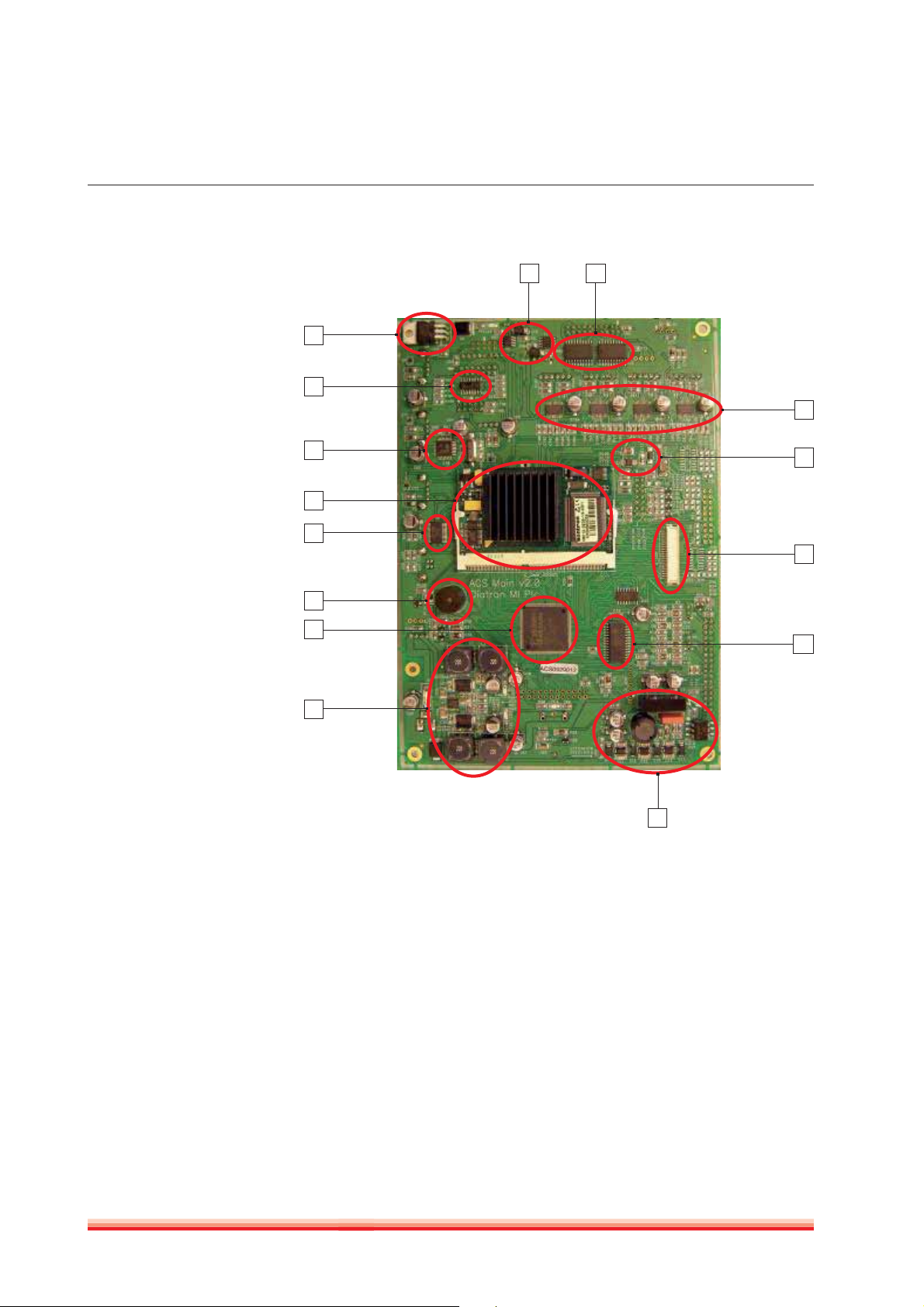
3.1.5 MAIN CPU BOARD
This board contains:
- DIMM-PC and measurement processing unit,
- 4 motor controllers,
- valve & pneumatic controller/drivers, pump driver(s)
- power supply for internal printer (+7.5V) and digital circuitry (+5V, +3.3V)
MAIN board is responsible to control the instrument: contains the main power
regulator circuits, valve and motor driver circuits and other connections for the
fluidic and pneumatic system’s parts, responsible for the specific measurement
processing functions.
The central micro-controller with a FPGA and with several other digital chips
(buffers, decoder, multiplexer) handles the pneumatic system, displaying,
measurement and data management.
Power system: filtering the +12V Input and generates +3.3V (FPGA), +5V (Digital
power), +7.5V (Printer power). Filtered +12V is used for the power of motors and
valves.
Motor drivers: 4 power drivers; Horizontal, Vertical/Sample rotor motors and
dilutor motors (2 in HC60TS) have separated ribbon cable connections.
Valve driver: consists two 8-bit, powered output shift registers (with built in
protection diodes) and there is one common ribbon cable connection for the
valve boards. The peristaltic pump has a separated power FET driver circuit for
more reliable operation.
Measurement processing: the A/D conversion made by the microcontroller itself, but several preprocessing steps (time limits, noise handling,
pulse integration) taken by the external analog circuitry.
20
1415
FIGURE 9
Main board - front view
1 Power Supply
for internal printer 7.5 VDC
2 Opto detectors` shift regi-
ster
3 USB HUB
4 DIMMPC
5 RS232/USB Converter
6 Speaker
7 FPGA
8 Power Supply 12VDC-
>5VDC, 3.3VDC
9 High Voltage Circuit 12VDC
-> ±12VDC, 50VDC for
measurement, 150VDC for
cleaning
10 Microcontroller
11 TFT connection
12 TFT backlight driver
13 Motor drivers
14 Valve drivers
15 Pump drivers
1
2
13
3
4
5
6
7
8
12
11
10
9
HumaCount 30TS / 60TS | Service manual
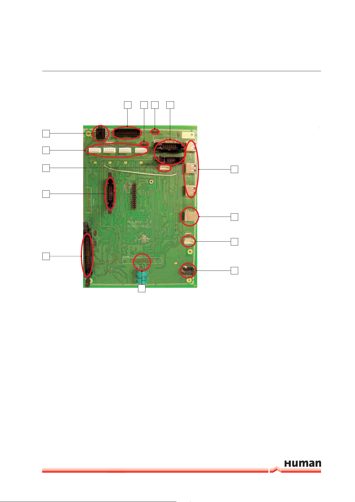
FUNCTIONAL DESCRIPTION 21
14
1113 12
FIGURE 10
1
2
Main board - rear view
1 Pressure Sensor
3
2 Motor Connectors
10
3 Front Panel USB Connector
4 Connector to TFT, Backlight
4
and Start Button
5 Connectors to Amplifiers
6 Internal battery
9
7 Power Connector
8 Power Switch Connector
9 USB B Type Interface
8
10 USB A Type Interfaces
5
6
11 Connectors to Optos
12 Pump Connector #1
13 Pump Connector #2 (HC60TS
7
Only)
14 Valves Connector
22
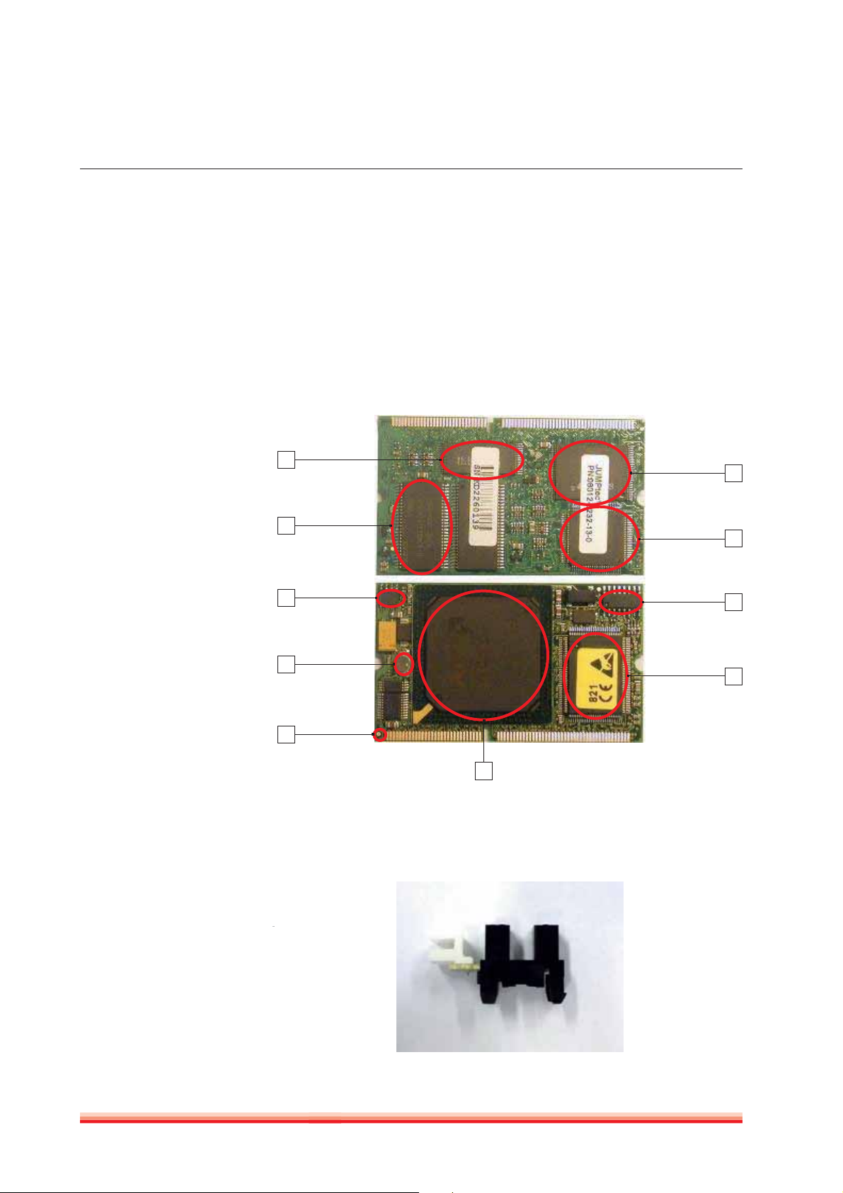
FIGURE 11
DIMM-PC
3.1.6 DIMM-PC* MODULE
The MAIN board incorporates a credit-card sized PC, named Dimm-PC*. The
processor on the Dimm-PC is a 133MHz Pentium-class core, with 32Mbytes
on-board RAM, and 32Mbytes on-board flash. This is the SSD (Solid State Disk)
of the analyzer, so instrument software with all user settings, calibration, database, etc. is stored on the Dimm-PC.
* DimmPC® is the Trade Mark of Kontron Embedded Modules GmbH
1
10
1 Flash BIOS
2 32 Mbytes RAM
3 CMOS EEPROM
4 On-board SMPS
5 Edge connector
6 AMD Elan SC520 CPU
7 Super I/O
8 Realtime clock
9 SSD controller
10 SSD
FIGURE 12
Opto sensor
2
3
4
5
6
9
8
7
3.1.7 OPTO SENSORS
Opto sensor snap-in modules are responsible for checking motor positions.
There are 6 opto sensors in HC60TS, and 5 in HC30TS (see cabling diagram).
HumaCount 30TS / 60TS | Service manual
FUNCTIONAL DESCRIPTION 23
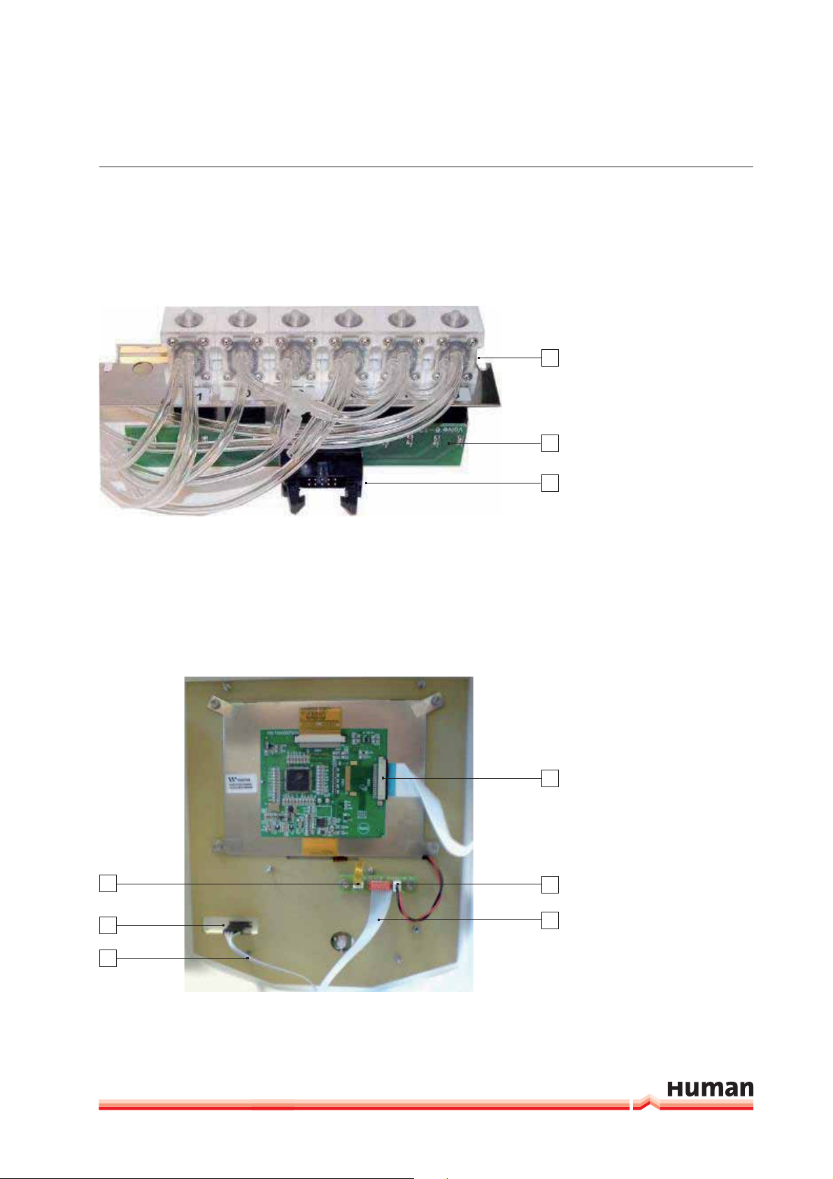
3.1.8 VALVE BOARDS
There are two kinds of valve boards: Valve board 1-5 and Valve board 6-12.
FIGURE 13
Valve assembly
1
1 Valves
2 Valve Board
3 Connection to Main board
2
3
HC30TS has 5 valves, while HC60TS has 6 valves in Valve board 6-12 module.
The valve boards are connected to controller and driver chips which are located
on the MAIN board.
3.1.9 TFT DISPLAY AND START BUTTON BOARD
1
2
3
FIGURE 14
Front panel connections
1 Touchscreen connector
2 Start button & status LED
4
connector
3 Ribbon cable from TFT/
Touch board to Main board
4 TFT connector to Main board
5 TFT Backlight connector
5
6 Ribbon cable from TFT/
Touch board to Main board
6
 Loading...