

Human Elisys 2 User manual

User Manual
!"#$%$&'
Cat.-No.: 17300/1
!

(!)#$#*+&"#$,&*-&,.!&/0+10"
No. DATE / Rev. REVISION DESCRIPTION
0 990614 Preliminary issue
1 000727 NEW: Block- and Group-Definitions
2 000915 NEW: Spare Parts, Page 55
NEW: Rack definition, Page 56
3 000921 NEW: External Incubation, Page 45;
NEW: Single step operations, Page 30
4 000925 CHANGE: Maintenance, Page 46
NEW: Change syringe tip, Page 48
CHANGE: Decontamination procedure, Page 47
5 020423 NEW: Software Version 3.28
CHANGE : Spare Parts- Consumables, Page 68
6 030217 NEW: Integration of new ELISA Tests
CHANGE: Updated rack description
User Manual ELISYS 2 Rev. 6 1/75

,234&4356&7689&:7;<=
2/75 User Manual ELISYS 2 Rev. 6

>*+,!+,$
INTRODUCTION 5
0.1. Description 5
0.2. User Warranty 5
SECTION 1 7
GENERAL SAFETY WARNINGS 7
1.1. Danger-Warning Symbols 7
1.2. Intended Use of the Instrument 7
1.3. Use of the Instrument 8
SECTION 2 9
GENERAL INFORMATION 9
2.1. Instrument Description: Purpose and Features 9
2.2. Manufacturer’s Identification Label 9
2.3. Instrument Description 10
2.4. Instrument Measuring Principle 11
SECTION 3 12
INSTRUMENT TECHNICAL DATA 12
3.1. Main Features 12
3.2. Instrument Technical Specifications (*) 13
SECTION 4 15
INSTALLATION AND START-UP INSTRUCTIONS 15
4.1. Unpacking 15
4.2. Placing the Instrument 16
4.3. Power Supply 16
4.4. Wash And Waste Container Installation 17
4.5. Work Area 18
4.5.1 Samples Tray 19
4.5.2. Trays for Reagents and Controls 19
4.5.3. Pre-dilution Plate 19
4.5.4. Microplate 19
4.5.5. Wash Basin for the Needle 19
4.5.6. Reader – Washer Group 19
4.6. Elisys 2 - PC Connection 20
4.7. Software Installation on PC 20
4.7.1. PC Minimum Requirements 20
4.7.2. Software Installation 20
SECTION 5 21
OPERATING INSTRUCTIONS 21
5.1. Introduction 21
5.1.1. Operating Overview 21
5.1.2. Powering the Instrument 22
5.1.3. PC program starting 22
5.1.4. Operating Menu 22
5.2. Work Session Setup 24
5.2.1. Select Profile 25
5.2.2. Set Parameters 26
5.2.3. Sample Setting 27
5.2.4. Single Step Operation 28
5.2.5. Entering the Patient Card 31
5.3. Run Analysis 32
5.3.1. Run the Process 33
5.3.2. Work Area Preparation 33
5.3.3. Analysis Execution (Running Phase) 34
5.3.4. Displaying the Results and their Acceptance Evaluation 35
5.3.5. Patient Reports 36
5.4. Databases 37
5.4.1. Medical reports 37
5.4.2. Patient Cards 38
5.4.3. Notes 39
5.4.4. Assays 39
User Manual ELISYS 2 Rev. 6 3/75

5.5 Assay Parameter Setup 40
5.5.1 Working Parameters 47
5.6 Rack Arrangements 53
5.6.1 Disposition on the Working Area- Standard Racks 53
5.6.2 Disposition on the Working Area -Universal Racks 54
5.6.3 Disposition on the Working Area - Mixed Arrangement 54
5.6.4 Working with two Substrates 55
5.6.5. Definitions for BLOCK-, RACK TYPE- AND GROUP PARAMETER 55
5.7. Settings 56
5.7.1 Break on error 56
5.7.2 External Incubation 56
5.7.3 Simulation mode 57
5.7.4 92 Positions for predilution 58
5.7.5 Substrate incubation at 37° 58
5.7.6 Dilution and wash buffer names 58
5.8 Commands 59
SECTION 6 60
MAINTENANCE 60
6.1. Checks and Preventive Maintenance 60
6.2 Cleaning the Instrument’s Parts 61
6.3 Tubing, Diluter and Manifold Decontamination 61
6.4 General Inspections and Checks 61
6.5 Replace the Syringe Tip 62
SECTION 7 63
PUTTING THE INSTRUMENT OUT OF SERVICE 63
7.1. General Warnings 63
7.2. Put the Instrument out of Service 63
7.2.1. Momentary Stocking 63
7.3. Instrument Transport and Handling 64
7.4. Instrument Storage 64
APPENDIX A 65
INSTRUMENT DECONTAMINATION 65
Decontamination Procedure 65
Decontamination Declaration 66
APPENDIX B 67
Spare Parts – Consumables – Accessory Parts 67
APPENDIX C 68
ELISYS 2 Rack Description 68
APPENDIX D 69
Group – Rack-Block -Division 69
APPENDIX E 70
Definitions for Groups 70
Group No.1 70
Group No.2 70
Group No.3 71
Group No.5 71
Group No.20 72
Group No.131 72
APPENDIX F 73
On Line Module 73
APPENDIX G 75
Operating Flow Diagramm 75
4/75 User Manual ELISYS 2 Rev. 6

#+,(*?1>,#*+
@ABA ?64CD3E93F<
The purpose of the automated microplates analyzer ELISYS 2 is to analyse samples on microplates; it
has been specifically conceived to automatically process up to 2 plates on line.
This manual provides the operator with all the necessary instructions for a safety, suitable use as well as
the instrument maintenance recommendations.
Manual content:
G& 3<9DF5HC93F<&
G& 46C93F<&B&G&
G& 46C93F<&'&G&
G& 46C93F<&I&G&
G& 46C93F<&J&G&
G& 46C93F<&K&G&
G& 46C93F<&L&G&
G& 46C93F<&M&
G& 46C93F<&N&
This manual is considered as a part of the instrument; it has to be at the operator’s hand as well as at
the maintenance operator’s availability.
For accurate installation, use and maintenance, please read the following instructions carefully.
In order to avoid instrument or personal damages, carefully read the ”GENERAL SAFETY WARNINGS”
Section 1, describing the suitable operating procedures.
In case of breakdowns or any troubles with the instrument, apply to the local Technical Service.
@A'A 146D&O;DD;<9P
HUMAN warrants that instruments sold by one of its authorised representatives shall be free of any
defect in material or workmanship, provided that this warranty shall apply only to defects which become
apparent within one year from the date of delivery of the new instrument to the purchaser.
- warranty information and the CE conformity declaration
general safety-warnings;
general information such as the producer data, instrument description;
instrument performances, technical data;
installation and start up;
operating instructions;
the user’s periodic maintenance and checking and the repair policy;
- how to put the instrument out of service, packaging, transport instructions;
– Appendices including instrument decontamination and spare parts list .
The HUMAN representative shall replace or repair any defective item at no charge, except for
transportation expenses to the point of repair.
This warranty excludes the HUMAN representative from liability to replace any item considered as
expendable in the course of normal usage, e.g.: lamps, valves, syringes, glassware, fuses, diskettes,
tubing etc.
The HUMAN representative shall be relieved of any liability under this warranty if the product is not used
in accordance with the manufacturer's instructions, not regularly maintained, used with equipment not
approved by HUMAN or used for purposes for which it was not designed.
HUMAN shall be relieved of any obligation under this warranty, unless a completed installation /
warranty registration form is received by HUMAN within 15 days of installation of this product.
This warranty does not apply to damages incurred in shipment of goods. Any damage so incurred shall be
reported to the freight carrier for settlement or claim.
User Manual ELISYS 2 Rev. 6 5/75

@AIA >!&>*+-*(/#,%
?!>"0(0,#*+&*-&>*+-*(/#,%
The producer declares that the instrument:
!"#$%!#&'(%)*+$,-!#&(!.!-/0&+
123456
%9:;<9=>;?43(<2?(@"%!.(A1B@(A4?19:C
*9>D(.2 EFGHH
conforms to the following EEC Directives, included the last modifications:
73/23/EEC regarding low voltage
89/336/EEC regarding Electromagnetic Compatibility
93/68/EEC regarding the CE marking
and that the below harmonized standard specifications have been applied:
Safety:
CEI EN 61010-1 (1994) / CEI 66-5 ” Safety requirement regarding electrical equipment for
measurement, control and laboratory use ”
Electromagnetic Compatibility:
Emission: EN 55011 (1989) (CEI 110-6)
Immunity: EN 50082-1 (1992) (CEI 110-8)
&-)7/7(8
The General Manager
6/75 User Manual ELISYS 2 Rev. 6
$!>,#*+&B
Q!+!(0"&$0-!,%&O0(+#+Q$
BABA ?;<R6DGO;D<3<R&$PS:F74
In this manual the following symbols are to remind the user of the safety rules:
This is a symbol of generic DANGER. It means that serious dangers might occur to the operator if
the described precautions are not fulfilled.
This is a symbol of high electrical voltage; by touching parts reporting this label, lif e endanger
might occur. Parts reporting this label can be handled only by qualified operators after having
unplugged the power supply cable.
This symbol indicates that the instrument makes use of chemical reagents and other dangerous
(corrosive, irritant and harmful) CHEMICAL SUBSTANCES which c an cause damages to people
and material. When this label is found, pay attention to the producer’s recommendations
This symbol indicates that the instrument involves the handling of s amples which can be infected
(urine and human serum). In this condition INFECTIONS or CONTAMINATION might occur. Pay
attention to the general safety warnings when in presence of such biological substances. Use
protective clothes, gloves and glasses.
This symbol indicates that damages to the instrument and/or its inc orrect results c ould occur if the
given warnings are not respected.
This symbol is to advise that the instrument or part of the manual which is particularly important
has to be consulted.
BA'A #<96<565&146&F8&926&#<49DHS6<9
The instrument is intended to be used in the following working conditions:
!
reading of medical substances as specified in the technical data;
!
only use the chemical reagents and accessories supplied and/or mentioned in this manual;
!
work at room temperature and humidity, according to the specified data;
!
do not power the instrument in a potentially explosive environment or at risk of fire.
The instrument has to be used as described in this manual. Any other use has to be regarded as
improper.
User Manual ELISYS 2 Rev. 6 7/75

BAIA 146&F8&926&#<49DHS6<9
The instrument has to be used for the expected purposes and in perfect technical conditions, by qualified
personnel, in working conditions and maintenance operations as described in this manual, according to
the safety rules.
This manual contains instructions for qualified operators.
!
TH;738365&146D
the use and maintenance are proper, according to the general safety rules as well as to the
particular precautions described in the manual (although he is not entitled to repair the instrument).
!
TH;738365& ,6C2<3C3;<
received and using the original spare parts.
has to make sure that environmental condition is suitable, the installation is correct,
is entitled to maintain and fix the instrument, according to the instructions
0796D;93F<4& F8& 9 26& 3<49DHS6<9& ;D6& EDF23:3965A& ,26& H46D& 34& 73;:76& 8FD& ;<P& 3<49DHS6<9& 3SEDFE6D
SF5383C;93F<&;4&U677&;4&926&56D3V3<R&CF<46WH6<C64A
Should the instrument need extraordinary maintenance, ask for
.HS;<&$6DV3C6&
or for licensed service
centres. The maintenance will be carried out by Specialised Technicians that will be able to fix the
instrument using the original spare parts to replace the defective ones.
8/75 User Manual ELISYS 2 Rev. 6
$!>,#*+&'
Q!+!(0"&#+-*(/0,#*+
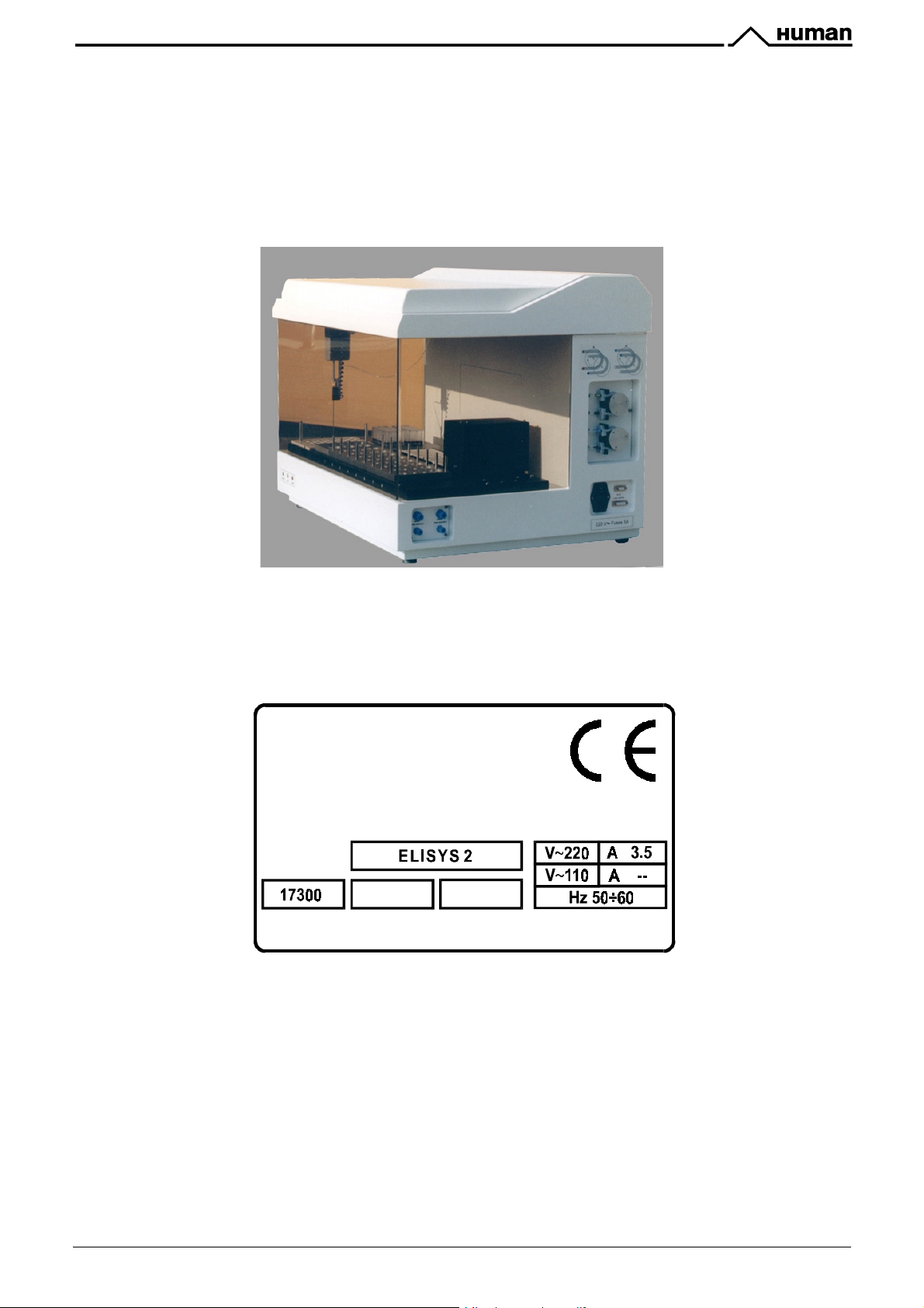
'ABA #<49DHS6<9&?64CD3E93F<X&YHDEF46&;<5&-6;9HD64
ELISYS 2 (fig.2.1) is an automated instrument designed to carry out tests on microplates by optical
density reading. It is able to mix organic samples (by pre-diluting them, if necessary) with reagents and
to process up to 2 plates on line.
'A'A /;<H8;C9HD6DZ48<9383C;93F<&";:67
/;56&3<&!>
/;<H8;C9HD65&8FD&.1/0+
QS:.&Q6DS;<P
0YY 0( AX
>;9AG&+F $!(#0"&+A
fig. 2.1
-0[(#>0,!?
User Manual ELISYS 2 Rev. 6 9/75
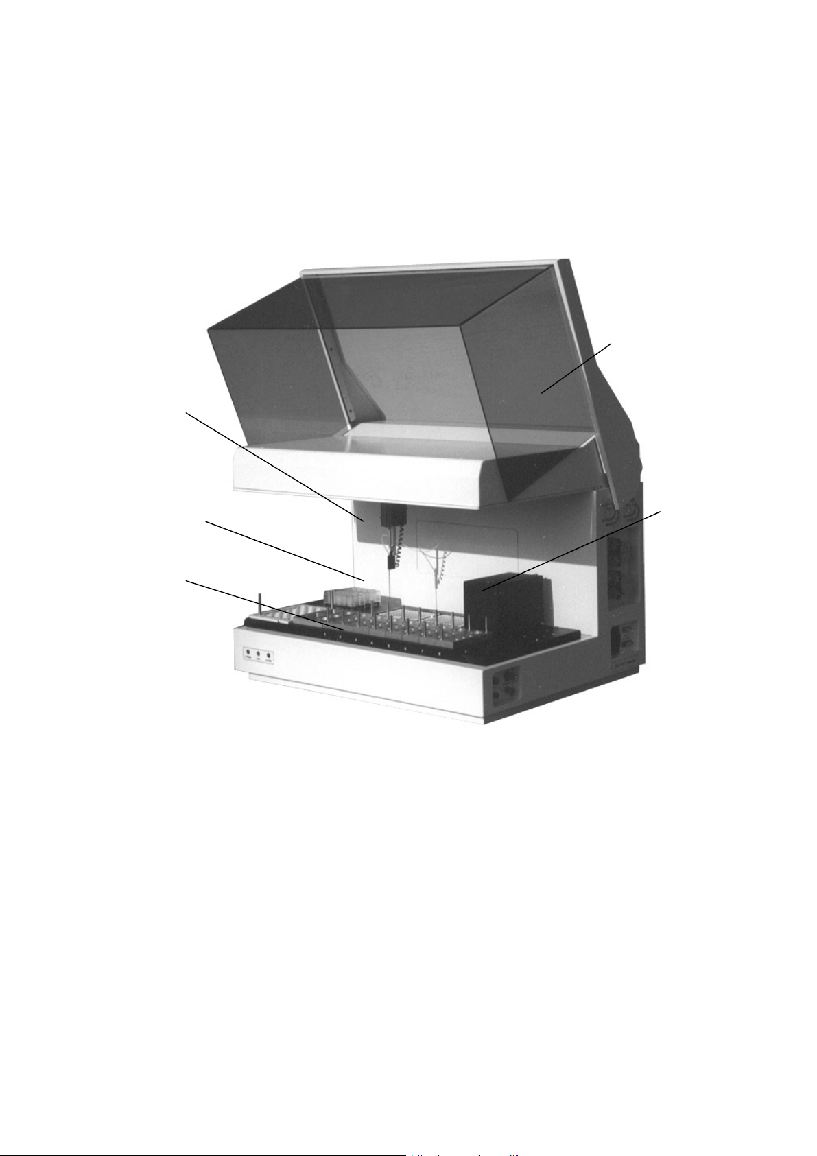
'AIA #<49DHS6<9&?64CD3E93F<
The instrument that is shown in figure 2.2 is composed of:
- Instrument framework and protection lid
- Control system run by electronic parts
- Aspirating and dispensing system
- Mechanical arm carrying a dispensing needle
- Movable photometer and plate washer
- Work area with: two microplate places, a washing basin, reagent trays, a tray for samples and two
predilution plates.
Arm
Needle
Protection lid
Photometer and
Plate washer
Work area
fig. 2.2 Front view (Lid lifted up)
10/75 User Manual ELISYS 2 Rev. 6
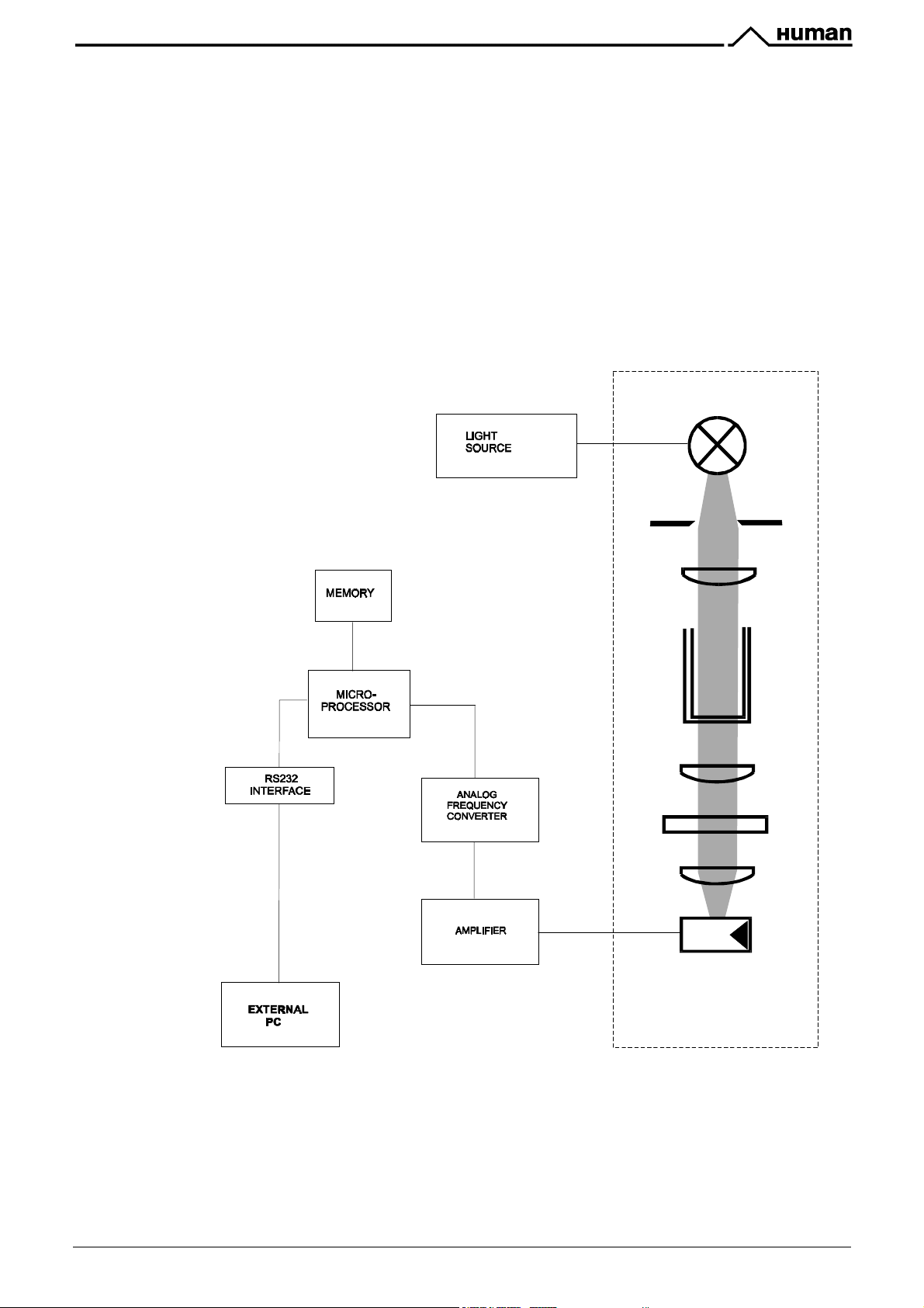
'AJA #<49DHS6<9&/6;4HD3<R&YD3<C3E76
Below (fig. 2.3) is the diagram representing the main functional elements of the instrument photometric
section.
A monochromatic filtered beam of light produced by a lamp goes through the well containing the sample.
Part of the light is absorbed by the sample, the remaining one is detected by a photodiode. The
photodiode converts the received light in an electrical signal that is once again transformed into
frequency. By this frequency the microprocessor calculates the absorbance, taking in account of the
blank measure carried out at the beginning. The following is the formula to calculate the absorbance:
!"#$%&'$()*+,-$./0120,345$6$%&'$(7+89*0$./0120,345
B&&&"0/Y&
'&&&"!+$
I&&&?#0Y.(0Q/
J&&&O!""
K&&&#+,!(-!(!+,#0"&-#",!( $
L&&Y.*,*?#*?!
1
3
2
4
2
5
2
6
X
8
fig.2.3
User Manual ELISYS 2 Rev. 6 11/75
channels

$!>,#*+&I
#+$,(1/!+,&,!>.+#>0" ?0,0
IABA /;3<&-6;9HD64
).7#+"%&.#(!)%
ELISYS 2 is a fully automated analyzer able to carry out up to 8 tests on two microplates.
7!%,-&7
Max capacity 40 samples in 16 mm primary tubes or 60 samples in 10 mm primary tubes (optional).
Samples predilution on two 20 well plates, programmable for each assay.
+&!A&.#7
Modular trays for calibrators, controls, conjugate, chromogen, stop solution, reagents and sample
dilution.
+&!*#)$.(!+&!
Max location of 2 microplates with 96 wells each which can be incubated at programmable temperature.
')7,&.7!#)$.
An arm with three directions (x, y, z axis) carrying a level sensor dispensing needle.
In the aspiration phase, the sensitive needle stops at liquid meniscus level to reduce contamination.
I!7@).A
Needle: external surface by dipping it into the washing basin with flowing water;
internal surface by dispensing the washing solution in the washing basin discharge.
Plates: one 8-channel dispensing manifold, able to run two independent washing solutions
one 8-channel manifold to drain a row of wells at one time
$,#)*!-(7/7#&%
Reader: 8 photometric channels equipped with lenses, interferential filters and lamps.
Results: available at the end of the work session to be stored and printed.
&J#&+.!-(-)K")'(*$.#!).&+7
External containers are delivered with the instrument to contain washing solutions, dispensing solution
and the liquids waste (each container is equipped with a level switch),
7$L#I!+&
A PC software, run by WINDOWS ’95/’98, allows to:
!
set up the requested analysis and to process on line different methods
!
give to the instrument the relevant commands
!
receive and transfer the analysis result
!
print and file the results
!
memorise the calibration curves.
12/75 User Manual ELISYS 2 Rev. 6

IA'A& #<49DHS6<9&,6C2<3C;7&$E6C383C;93F<4&\]^
PROCESS CAPABILIT Y
WORK AREA
" Microtiter plates
" Sample tray
" Common reagent trays
" Specific reagent trays
" Predilution plates
PREDILUTION
DISPENSATION
DISPENSATION SYRINGE
PIPETTING SPEED
CARRY OVER
LIQUID SENSORS
MICROPLATES W ASHING
NEEDLE W ASHING
" Total volume
" Minimum volume
" Accuracy
" Samples
" Reagents
" Sample dead volume
" R eagent dead volume
Combination up 8 ass ays on 2 micr otiter plates on line
Modular composition:
2 microplates with 96 wells (12 strips, each one with 8 wells)
one tray f or 60 primary tube Ø10#12 x 100 mm, replaceable with a 40 primary tube
Ø14#16 x 100 mm tray
different types (depending on the assay category), f or substrate, stop solution,
cleaner, dilution solution bottles, common reagents
different types (depending on the specific assay), for calibrators, controls, specific
reagents
2 plates, eac h one with 20-wells
Programmable for each sample,
Three freedom degr ees Arm (x, y, z axis) c arrying the needle
1000 µl
10 µl
Better than 1% at a volume of 100 µl
35 minutes for 96 wells for a washing volume of 1 ml
7 minutes for 96 wells for a washing volume of 1 ml
Minimis ed to less than 3% by washing the pipetting system after each single
sample dispensing and after each reagent dispensation phase
Sample and reagent levels are sensed by the needle used as a capacitive
sensor
Less than 150 µl
Between 100 µl and 400 µl depending on the bottles used
8-channel moving manifold with separate filling and aspiration ports
2 different washing s olution to choosing from within a work session
External and internal washing
REAGENT W ASTE
EXTERNAL TANKS
" Wash buffer 1and 2
" Wash solution
" Waste
INCUBATION
PHOTOMETER
" Light source
" Filters
" Detectors
" Measurement range
" Accuracy
from 0.000 to 1.500 OD
from 1.500 to 3.000 OD
" Stability (short term)
About 10% (*) of reagent aspirated for all the assays
(*) used for cleaning the sampling system
two 2-liter bottles
a 5-liter bottle
a 10-liter tank
Each one is equipped with a level switch to check whether the tank is full or empty
At room temper ature (Ta) or programmable from T a+5°C up to 45 °C in steps of
1°C
Moving 8 channel device with automatic blanking and internal calibration
Tungsten lamps
2 standard interferential filters: 450 and 630 nm, bandwidth 8 nm
Other wavelength values on request .Two more optional filters to be added .
Silicon photodiodes
0.000 - 3.000 OD (Optical Density)
$ 1% or $ 0.010 OD whichever the bigger
$ 2%
0.001 OD in 1 minute
User Manual ELISYS 2 Rev. 6 13/75

:;<=>?@A;=$=ABC;:BD%$<EAB:F:BD=:!;<
(B&,GH,20I5
SERIAL INTERFACE
ELECTRICAL POW ER REQUIREMENT Standard 220 or 110 Vac 50/60 Hz
RS232
POWER CONSUMPTION
OPERATING CONDITIONS
Temperature
Relative Humidity
SHELF CONDITIONS
Temperature
Relative Humidity
DIMENSIONS
" Width
" Height
" Depth
WEIGHT
" Instrument
" Packed instrument
EUROPEAN REFERENCE DIRECTIVES
HARMONIZED STANDARD
SPECIFICATIONS
INSTRUMENT OUTFIT
PC (optional supply)
(*) The described features can be altered at the producer’s discretion without f orewarning.
500 W Max
from +15°C to +30°C
up to 80%
from "10°C up to +60 °C
up to 85%
790 mm
595 mm (980 mm with lifted up lid)
600 mm ( 650 mm with lifted up lid)
72 Kg
97 Kg (wooden box dimensions: 89x68x75 cm)
" 73/23/EEC regarding low voltage electrical material
" 89/336/EEC regarding Electromagnetic Compatibility
" 93/68/EEC r egarding the CE mark
Safety:
EN 61010-1 (1994) / CEI 66-5 ”Safety requirements for measurement
electric al equipment checking and laboratory use”
Electromagnetic Compatibility:
Emission: EN 55011 (1989) (CEI 110-6)
Immunity: EN 50082-1 (1992) (CEI 110-8)
The instrument is equipped with:
! User’s manual
! Mains power cable.
! Modular reagents trays (kit)
! Two predilution plates
! A tray for 40 samples
! Two 2-liter bottles for wash buffer 1and 2.
! A 5-liter bottle for wash solution.
! A 10-liter waste tank
! RS232 PC connection c able
! Software for PC to master the instrument
! (On request: BDE Installer f or Microsoft Windows 98 II.Edition)
The PC minimum requirements are:
! Microsoft Windows 95 or 98 (for Microsoft W indows 98 II.Edition you
need the BDE-Installer version 1.0)
! 15 MB free on hard disk
! 1.44Mb floppy driver
! RAM 32 Mb
! Pentium or compatible processor at 166 MH z
! Display adapter standard VGA 640x480
! Printer
14/75 User Manual ELISYS 2 Rev. 6

$!>,#*+&J
#+$,0""0,#*+&0+?&$,0(,G1Y&#+$,(1>,#*+$
#<49;773<R&;<5&46993<R&HE& 926& 3<49DHS6<9_&926&4;869P&U;D<3<R4&;<5&R6<6D;7& DH764& 564CD3:65& 3<& $6C93F<&B
SH49&:6&F:46DV65A
O;D<3<R`&&U26<&SFV3<R&FD&73893<R&926&3<49DHS6<9&CF<4 356D&X
JABA 1<E;C=3<R
The instrument is packed with a plywood box, which can be easily moved by a lifting trolley.
Be careful when placing the instrument onto the work area.
To unpack the instrument follow the instructions as below described:
"
Remove the packaging band around the plywood box.
"
Lift the plywood box straight up from the bottom plate and place it beside the instrument.
"
Remove the packaging band and the protective plastic sheets around the instrument.
"
Unscrew the four 10 MA screws fixing the instrument body to the bottom plate of the box.
"
Save the empty box and the fixing screws for future transportation.
If the instrument was already in use check for the
manual).
Y"!0$!&$0)!&,.!&!/Y,%&[*b&`
used in future transportation.
#+$,(1/!+,&O!#Q.,&
!
Y0>a!?&#+$,(1/!+,&O!#Q.,&
!
?!>*+,0/#+0,#*+& ?!>"0(0,#*+
This box is designed and manufactured for this instrument only and should be
&N@&aR
%%%%
&B@@&aR
%%%%
(see Appendix A of this
User Manual ELISYS 2 Rev. 6 15/75

JA'A Y7;C3<R&926&#<49DHS6<9
The instrument has to be placed on a levelled bench, assuring enough free space around the instrument
to allow maintenance operations (35
Room temperature has to be between 10 and 30 °C with relative humidity below 80%; protect it from
direct sunshine.
JAIA YFU6D&$HEE7P
Once the instrument and its outfit have been placed, plug it to the right power source using the supplied
cable.
#
50 cm on the rear and on the lateral sides).
fig.4.1
O;D<3<RX&S;=6&4HD6&92;9&926&676C9D3C;7&EFU6D&4FHDC6&34&926&F<6&;4&D6WH64965&;<5&3<53C;965&F<&926
7;:67&:64356&926&3<49DHS6<9&EFU6D&4FC=69&`
c&&''@&)d&&FD&&BB@&)d&e
O;D<3<RX& S;=6& 4HD6& 92;9& 926& 8H464& V;7H6& CFDD64EF<54& 9F& 926& F<6& 3<53C;965& :64356& 926& 8H46
2F756D`
''@&);C&S;3<4&&&
BB@&);C&S;3<4&&&&
&&&&
&'&&WH3C=&8H464&IAK&0
&&&&
&'&&WH3C=&8H464&&&M&0
16/75 User Manual ELISYS 2 Rev. 6
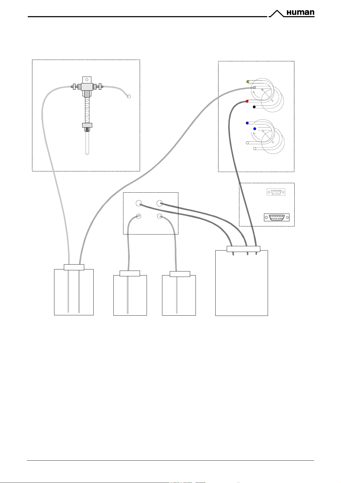
JAJA O;42&0<5&O;496&>F<9;3<6D&#<49;77;93F<
In figure 4.2 are shown the washing/discharging containers and their connections with the instrument.
$
Blank
Red
0
[
WASTE
WASTE
RS 232
LEV EL CONTROL
(
Wash
buffer 1
Blank
O0$.
O;42
:H886D&
&&&&B
$
0
[
,B
,'
,I
,J
,I
Precision Syringe
Peristaltic Pump for needle external washing
Peristaltic Pump for Microplate washer
O;42&:H886D&BX
O;42&:H886D&'X
O;42
: bottle for the needle ext ernal washing solution (see note 1).
O;496X&
tank to collect the waste.
bottle for the microplates washing solution (see note 1).
bottle for the microplates washing solution.
,B
Wash
buffer 2
O;42
:H886D&
&&&&'
,'
Red
O0$,!
,J
(
Level control connector
fig. 4.2
User Manual ELISYS 2 Rev. 6 17/75
0
Before switching on the instrument:
"
fill up the T1, T2, T3, bottles with the right solution according to the method requirement
"
place the T4 empty container (waste)
"
connect the tubing to their relevant container as shown in figure 4.2.
"
make sure that the tubing are properly connected and that they are in good condition.
"
plug the lead of the level sensor to the instrument socket (connector R).
;&G0$J$K$DG$GL0$0,I$&.$+$M&/-$7077H&,N$&/$.&/$73L0I2*0I$8+H,G0,+,30N$GL0$H,7G/280,G$/012H/07$+$M+7LH,'$343*0O$:,$GLH7$3+7
P
"
)&GG*0$ =J$ L+7$ G&$ )0$ 72)7GHG2G0I$ MHGL$ +,$ 012HQ+*0,G$ )&GG*0$ 3&,G+H,H,'$IH7GH**0I$ M+G0/$ &/$I03&,G+8H,+GH,'$ 7&*2GH&,$.&/
8+,H.&*I$3*0+,H,'$(700$<03GO$R5O
"
)&GG*0$=S$L+7$G&$)0$72)7GHG2G0I$MHGL$+,$012HQ+*0,G$)&GG*0$3&,G+H,H,'$I03&,G+8H,+GH,'$7&*2GH&,$.&/$,00I*0$H,G0/,+*$+,I
0TG0/,+*$3*0+,H,'$(700$<03GO$R5O
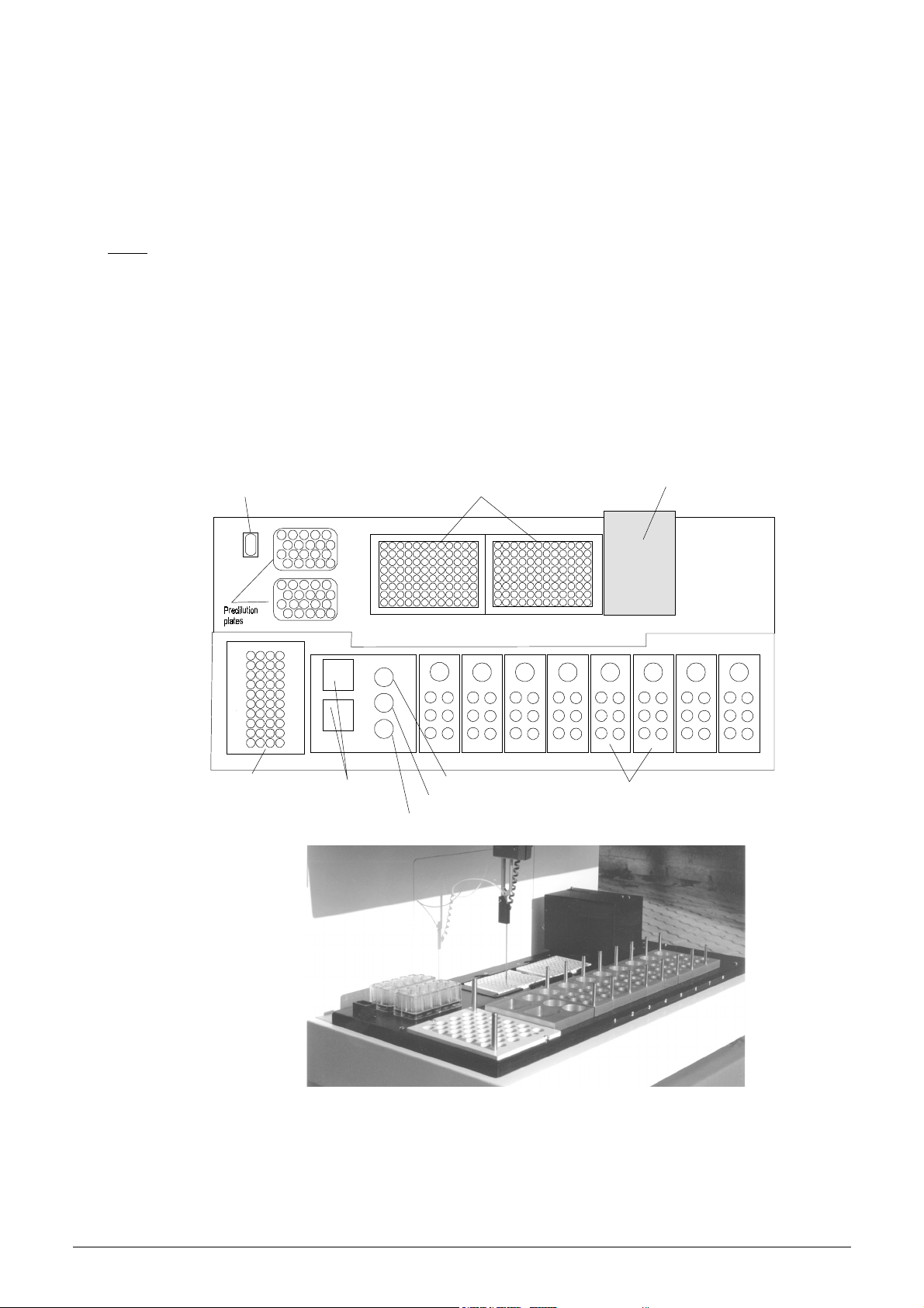
JAKA OFD=&0D6;
Figure 4.3-a and fig.4.3-b show a typical work area layout.
Needle
Washing
basin
Micropla te s
Reade r/ W asher
Group
1
11
21 31
2
3
4
5
6
7
8
9
10
Samples
tray
Dilution
solution
bottles
S u b str ate
S top so lu t io n
Cleaner
Reagents
tray s
fig. 4.3 - a
fig. 4.3 - b
18/75 User Manual ELISYS 2 Rev. 6
JAKAB $;SE764&,D;P
The sample tray is a support for sample vials (primary tubes) to be analysed.
The tray may be for 60 primary tubes sized 10#12 mm in diameter and 100 mm in height (optional) , or
40 primary tubes sized 14#16 mm in diameter and 100 mm in height.
Vials are manually loaded, according to the program instructions (see paragraph 5.3).
JAKA'A ,D;P4&8FD&(6;R6<94&;<5&>F<9DF74
Different types of reagent trays may contain dilution solutions, substrate, stopping solution, cleaner,
conjugate, calibrators and controls. Part of them are common for all the assay methods of the session,
wile other trays contain the reagents for the specific assay methods.
The reagent vials have to be placed on particular positions as shown as typical example in fig. 4.3-a and
according to the given program instructions (see paragraph 5.3) for the specific assay method.
JAKAIA YD6G537H93F<&Y7;96
The pre-dilution plate is a molded 20 wells plastic container. The needle dispenses the sample along
with dilution solution into each cup according to the running program.
There are two pre-dilution plates, so that a total of 40 pre-dilution cups are available.
The program advises to locate the pre-dilution plates before starting the process (see paragraph 5.3).
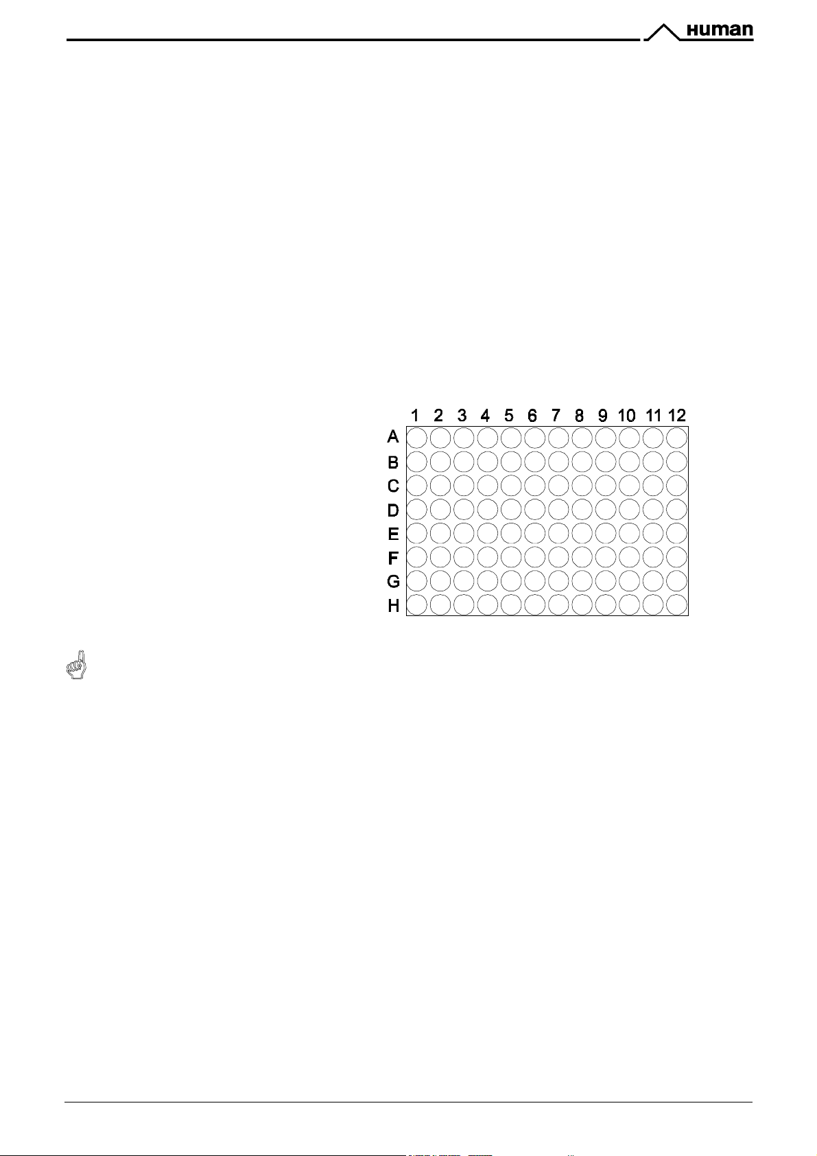
JAKAJA /3CDFE7;96
The microplate is a support for 96
reaction wells. One or two microplates
have to be located on their relevant
places.
The washer and the photometer are able
to run through the plate in order to read
and wash the related wells.
Each microplate can host up to 12 strips,
each strip containing 8 wells.
The PC program advises to locate the
microplates before the start of the
running process (see paragraph 5.3).
I9?:M:N6(>2(O?4P4:>(M:Q>?;14:>(>?2;B54Q(3;?M:N(1M=?2O59>4(R9QSM:N(Q4T;4:=4U(955(>S4(?4T;4Q>43(Q>?MOQ(1;Q>
B4(=21O54>43(RM>S(>S4(V(R455Q(W
JAKAKA O;42&[;43<&8FD&926&+66576
In order to wash the external part of the dispensing needle, it is dipped into the wash basin where the
washing liquid continuously flows. To wash the internal part of the needle the dispensation liquid is
pumped into it.
To prevent samples contamination, the needle washing system is automatically activated, when
necessary.
JAKALA (6;56D&f&O;426D&QDFHE
The reader–washer group is located on the top of the microplates area. It allows to run automatically
both the photometric reading and the microplates washing, in succession according to the program.
fig.4.3 -b
User Manual ELISYS 2 Rev. 6 19/75
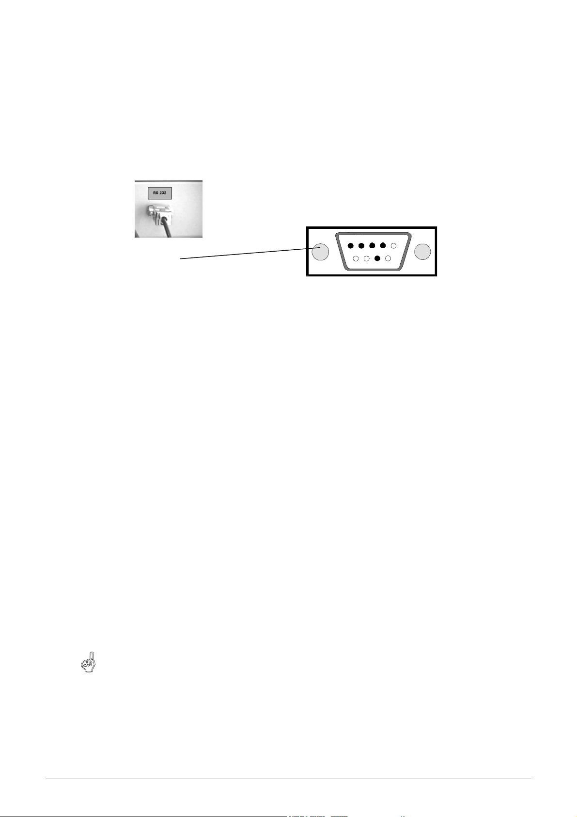
JALA !734P4&'&G&Y>&>F<<6C93F<
The instrument is equipped with an RS232 serial port for PC connection.
A 9-pin connector is available on the instrument right side panel (see fig. 4.4).
Generally two serial ports to choose from are located on the rear panel of a PC: COM1 and COM2, a 9pin male connector and/or a 25-pin male connector.
A connection cable PC- ELISYS 2 with two 9 pin connectors (female- male) is supplied with the
instrument. An adapter 9-25 pin may be necessary on the PC side connection.
Fig. 4.4 RS232 serial port located at the instrument right side
JAMA $F89U;D6&#<49;77;93F<&F<&Y>
JAMABA Y>&/3<3SHS&(6WH3D6S6<94
"
Microsoft Windows 95 or 98
"
15 MB free on hard disk
"
1.44 Mb floppy driver
"
RAM 32 Mb
"
Pentium or compatible processor at 166 MHz
"
Display adapter standard VGA 640x480
"
Printer .
JAMA'A $F89U;D6&#<49;77;93F<
AP 2 is the program specifically developed for ELISYS 2.
5
2
374
2 Tx
3 Rx
4 DTR
5 GND
7 RTS
To install AP 2 program on the PC place ELISYS 2 CD in the CD-ROM drive. If the installation program
does not start automatically, proceed as follows:
"
Start Explorer from the Start menu and select the letter of the CD drive.
"
Start the
$69HEA6g6
program by double clicking with the left key on the mouse.
The installation program is now initialised. Follow the instructions shown on the screen.
The program is now installed and the ELISYS 2 icon is available on the desktop. Double click on it to run
the program.
+419?X6(L2?(%M=?2Q2<>(IM:32RQ(YV())D&3M>M2:(C2;(:443(>S4(Z'&[):Q>9554?(P4?QM2:(EDH
\(Q>9?>(Z'&[):Q>9554?(95Q2(RM>S(74>;OD4]4^D
20/75 User Manual ELISYS 2 Rev. 6
$!>,#*+&K
*Y!(0,#+Q&#+$,(1>,#*+$
KABA #<9DF5HC93F<
KABABA *E6D;93<R&*V6DV36U
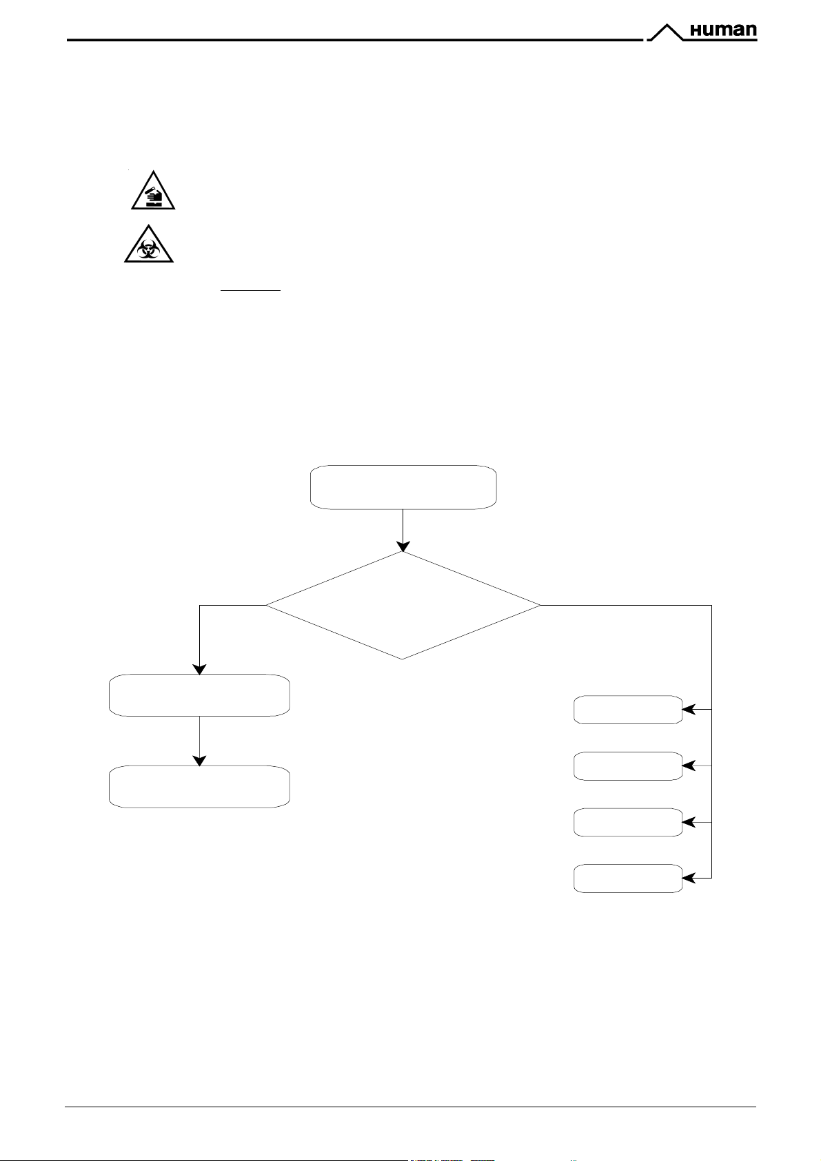
Table 5.1 shows the general operating sequence.
The instrument requires the use of chemical reagents and other dangerous (corrosive, irritant and harmful)
CHEMICAL SUBSTANCES which can cause damages. When this label is found, be careful and pay attention
to the producer recommendations
The instrument requires to handle samples which can be infected (urine and human serum). In this condition
INFECTIONS or CONTAMINATION might occur. Pay att ention to the general safety warnings as to the
presenc e of such biological substances. Use protective clothes, gloves and glasses.
In particular:
!
Wear protective clothes and gloves.
!
At the end of a work Session, clean the work panel and its acc essories carefully by using a cloth s oaked
in a 0.5% sodium hypochlorite solution.
!
Waste material produced by the analytic al and cleaning process is a dangerous material which might
contaminate people and material. Get rid of the waste material according to the local regulations.
PC switch ing on
and program start
WO RK SESSION
Work session
setup
Run Analysis
Start w ork ses sion
or
other functions?
Par. 5.2
Par. 5.3
,;:76&KAB&f&Q6<6D;7&FE6D;93<R&87FU&53;RD;S
OTHER FUNCTIONS
Par. 5.4
Par. 5.5
Par. 5.6
Par. 5.7
Databases
Settings
Commands
Help
User Manual ELISYS 2 Rev. 6 21/75
KABA'A YFU6D3<R&926&#<49DHS6<9
Switch on the instrument (the switch is located on the right side).
On the front side of the instrument there are three coloured lamps as below specified:
Y*O!(
(1+
!((*(
green lamp
yellow lamp
red lamp
;&G0$JP$=L0$8+3LH,0$M&,UG$7G&9N$)2G$GL0$IH79*+4$7L&M7$GL0$Q&HI$9&7HGH&,7O
KABAIA Y>&EDFRD;S&49;D93<R
The ELISYS 2 icon is available on the desktop. Double click on it to run the program.
indicating that the instrument is switched on
indicating that the instrument is in running phase
indicating that no liquid is inside some container of the work panel
;&G0$J
(
)
The main menu will appear:
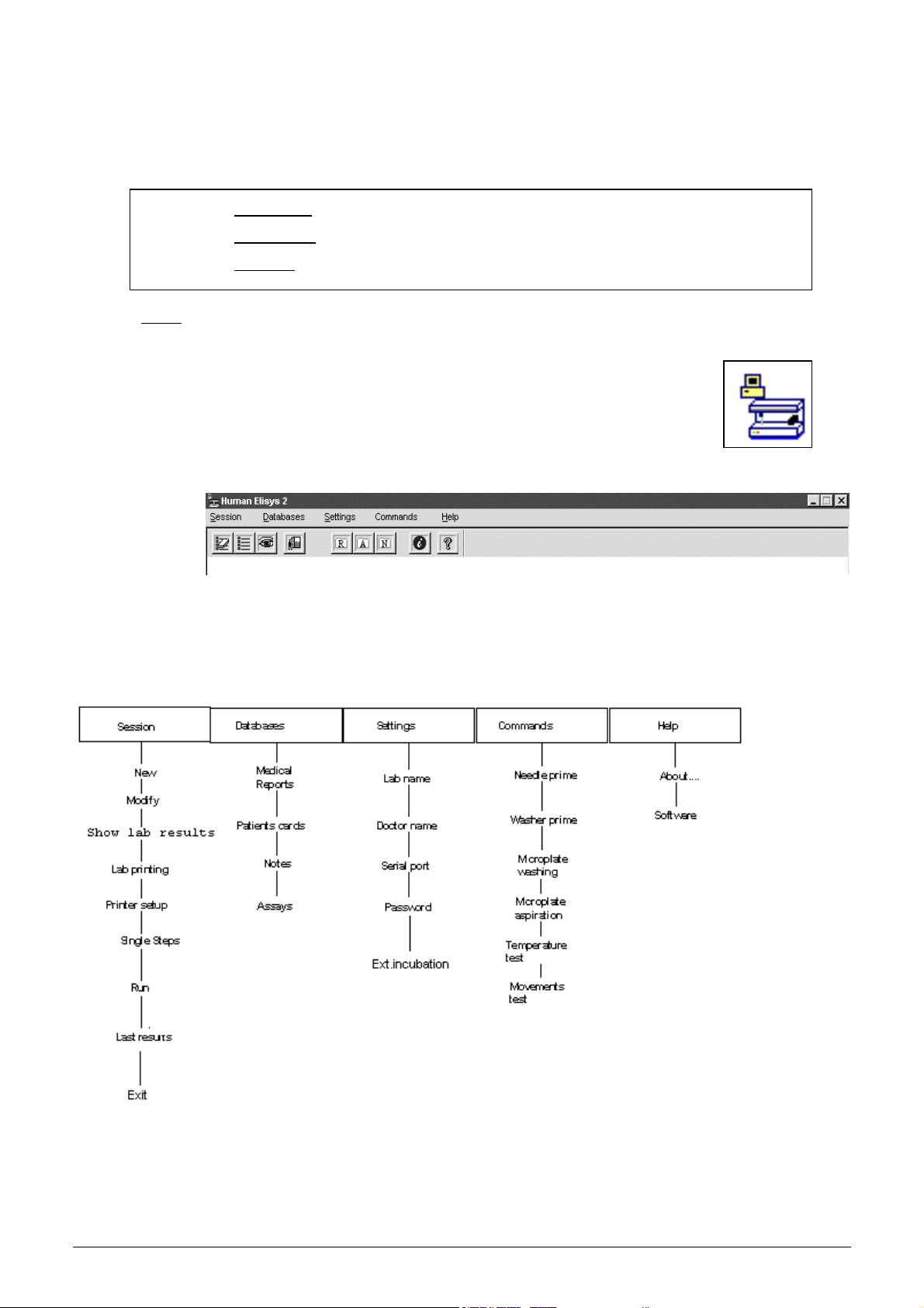
KABAJA *E6D;93<R&/6<H
Tables 5.2 and 5.2a show the instrument operating menus and their function.
/6<H&8H<C93F<&6gE7;<;93F<
22/75 User Manual ELISYS 2 Rev. 6

$6443F<
New To start a new work session.
Modify To modify the setting of the last loaded session, if processed or not. If no
session has been programmed, it assumes the New function as the previous
paragraph.
Show lab results Display of existing Labfiles
Lab Printing To print all the information concerning each analysis session already
processed, values for the samples, controls and standards, as well as any
mistake if any.
Printer Set-up
Single Steps
To set up the printer
Activates the single steps operation
Run This command runs the working procedure, if a session has been set up.
Last results
display
Activates the display of the results of a processed but not stored working
session.
Exit Exit from the program.
?;9;:;464
Medical report Displays the stored medical reports. They can be accessed or by the
patient's name and/or the execution session date.
Patient card To display, modify and insert the patients in the database.
Notes To display, modify and insert the sentences frequently used and associated
to the notes in the report.
Assays To display, modify and insert the parameters for each method.
$6993<R4
Lab name To set the heading to be printed on the lab printing reports.
Doctor’s name To indicate the doctor's name on the analysis report.
Serial port To choose the serial port or simulation mode
Password To insert or modify the password.
Ext. incubation Enables the external incubation function.
>FSS;<54
Needle prime To prime the needle.
Washer prime To prime the washer.
Micro-plate
To set the number of strips to be washed.
washing
Micro-plate
To set the number of strips to be emptied.
aspiration
Temperature test To set the reference temperature and to monitor it continuously.
Movements test To check the instrument's moving parts and show any bad functioning.
.67E
About…. To display all the information concerning that software version.
Software To display the software interactive guide.
User Manual ELISYS 2 Rev. 6 23/75
 Loading...