

Page 1

Service Documents
Confidential, for authorized service technicians only!
Do not disclose this information to or share these documents
with third parties.
Vertraulich! Nur für autorisierte Servicetechniker!
Nicht zur Weitergabe an Dritte freigegeben!
TECHNICAL SERVICE:
Stamer Musikanlagen GmbH • Magdeburger Str. 8 • 66606 St.Wendel • Germany
Music & Sales P.E. GmbH • Leipziger Str. 3 • 66606 St.Wendel • Germany
Note!
The components used in this product - particularly parts affecting
safety as well as speakers and transformers - were developed and
manufactured to certain specifications. Please use original spare
parts only to ensure the product remains fully functional and safe.
Achtung!
Die in diesem Produkt verwendeten Komponenten, insbesondere
sicherheitsrelevante Teile, Lautsprecher und Transformatoren
wurden nach spezifischen Vorgaben entwickelt und gefertigt.
Bitte benutzen Sie ausschließlich Original-Ersatzteile – nur so ist
die volle Funktionalität und Sicherheit gewährleistet.
L.U.C.A.S
XT
31.10.07
Page 2

Directory
features
drawing-numbers-example
standard for single wire confection
HK2001- L.U.C.A.S XT
exploded drawings:
layout diagrams
page: 3-10
page: 11
page: 12
page: 13
top complete Rev.: B page: 14-15
top front grille Rev.: B page: 16
top cabling Rev.: B page: 17
sub complete Rev.: B page: 18-19
sub front grille Rev.: A page: 20
sub chassis/ cabling Rev.: H page: 21-24
preamp Rev.: H page: 25-26
circuit diagrams
poweramp/powersupply Rev.: E page: 27-28
crossover Rev.: B page: 29
preamp Rev.: H page: 30-35
poweramp/powersupply Rev.: F page: 36-40
crossover Rev.: B page: 41
Page 3
L.U.C.A.S XT Manual 2.0
Welcome to the
HK AUDIO
®
family!
Thank you for choosing (another) HK AUDIO
®
product.
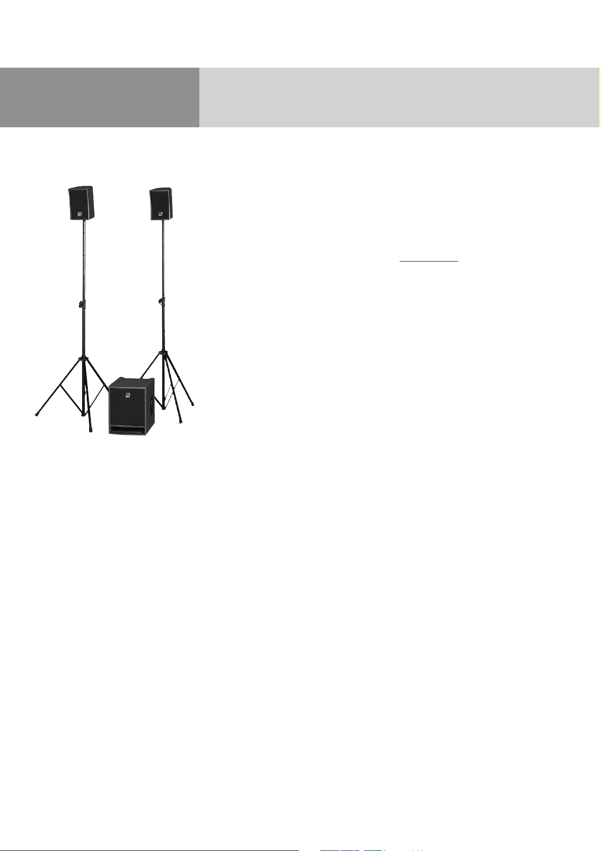
L.U.C.A.S
®
XT consists of two satellites and a compact subwoofer equipped with a power amp and all
the electronics required to drive the bass bin and
satellite. Painstakingly fine-tuned to match the
speakers for superior impulse response and the
best possible sound, the electronic circuitry makes
the system easy to handle and protects it from
overloads. You don't have to worry about tweaking
frequencies and finessing levels, all you have to
do is set up the system components, connect the
signal-carrying cords and power cable, and you're
ready for action.
Every HK AUDIO
®
active system is much more than
just a cabinet with an onboard power amp. Each
one is a full-fledged sound reinforcement solution
consisting of a subwoofer, satellite and meticulously
matched electronics. Our engineers brainstormed
new technologies specifically to satisfy stringent
performance requirements. Unique and sophisticated,
these features make an active HK AUDIO
®
sound
reinforcement system stand out from the crowd.
Warranty
Register your L.U.C.A.S®XT using the enclosed
warranty card to extend your warranty to five years
free of charge.
Use the convenient Online Registration option at
www
.hkaudio.com
If you are unable to register online, please fill out the
enclosed warranty card completely and mail
or fax it to us. The registration is only valid if the
warranty registration card is filled out and returned
to HK AUDIO
®
or the device is registered via the
Internet within 30 days after the date of purchase.
We are also interested in learning where and by
whom our devices are used. This information will
help us design future products. Your data is of course
protected by privacy laws.
Thank you.
HK AUDIO
®
Technical Service
Postfach 1509
D-66595 St. Wendel, Germany
Table of Contents
1 L.U.C.A.S®XT’s Control Features . . . . . . . . . . . . 6
2 Setting Up and Connecting L.U.C.A.S
®
XT . . . . 7
3 Mounting Satellites on Speaker Stands . . . . . . . 7
4 Operating the System . . . . . . . . . . . . . . . . . . . . 8
5 Settings . . . . . . . . . . . . . . . . . . . . . . . . . . . . . . . 8
6 L.U.C.A.S
®
XT Accessories . . . . . . . . . . . . . . . . . 9
7 Tips and Tricks . . . . . . . . . . . . . . . . . . . . . . . . . . 9
8 Troubleshooting . . . . . . . . . . . . . . . . . . . . . . . . 10
9 Technical Specifications . . . . . . . . . . . . . . . . . . 11
Page 4
5
English
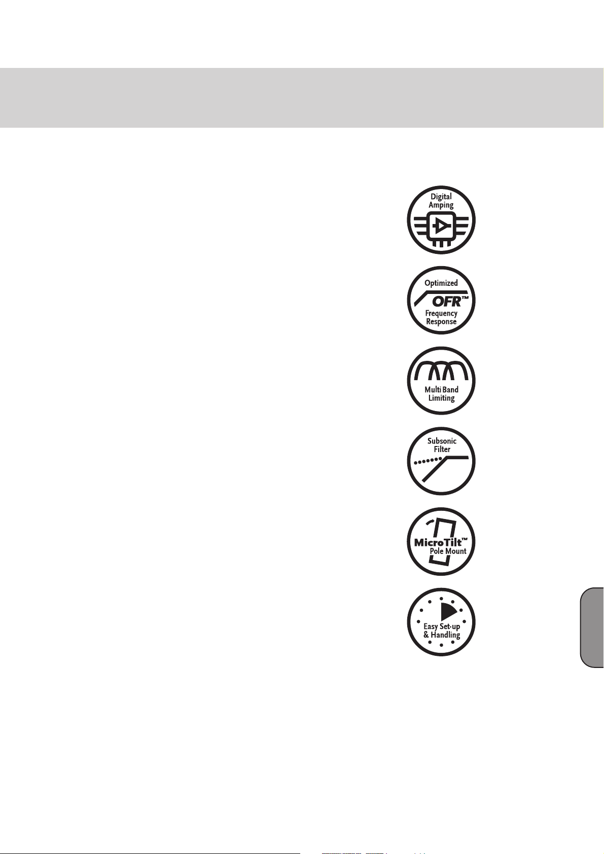
Digital Amping
Enhanced Efficiency and Dynamic Response
With an efficiency rating topping the 90% mark,
digital power amps are smaller, lighter, and more
compact than comparable conventional amps.
The reduced thermal load on components clearly
enhances reliability. The slew rate is far faster and
the damping factor is higher, resulting in audibly
more responsive and accurate performance.
• Outperforms analog power amps in efficiency for
greater reliability and lower current consumption
• Faster signal transmission for enhanced dynamic
response
OFR™
Optimized Frequency Response Technology
HK AUDIO
®
’s unique OFR™ technology deliver
commanding yet well-balanced sound at every level.
It corrects for non-linear frequency response in the
speaker components at the same time as it compensates for the way human hearing works at varying
levels.
• Fine-tuned to each system
• Rectifies non-linear frequency response
• Adapts the system to different volumes
• Powerful, balanced sound in every situation
MultiBand Limiting
Specialized limiting for each frequency range
Several limiters, each specializing in its own
frequency range, work side by side to keep the entire
system under control. This ensures even dynamic
response and punchy projection for a highly musical
sound across the entire frequency spectrum.
• Tighter low-end punch, snappier kick
• Clean, emphatic mids for smooth, rich vocals
• Transparent, glossy highs with extra headroom
• Speaker overload protection
Subsonic Filter
Preventing Low Frequency Interference
The integrated subsonic filter eliminates accidental
and unintentional signals such as footfalls, wind, or
the sound of a hand accidentally brushing a microphone. It cuts these frequencies drastically, freeing
energy to render bass impulses better. Goodbye
squashed dynamics and artificial sound, hello
authenticity and natural sounding low/mid
frequencies.
• Increases power and volume in the useful
frequency range
• Protects power amps and speakers from harmful
ultra-low frequencies
DuoTilt™ and MicroTilt™
Making the Most of Sonic Energy
The new DuoTilt™ and MicroTilt™ speaker stand
mounting collars allow sound energy to be utilized
far more efficiently. The DuoTilt™ offers downward
angles of 7.5° and 15°, and MicroTilt™ 10°, to better
aim the mid/high-range cabinets directly at the
audience. Troublesome ceiling reflections are
minimized; the soundscape is clearer, tighter, and
more focused.
• Tilts at angles designed for the best possible
alignment of the enclosure to the audience
• Minimizes ceiling reflections, maximizes energy
efficiency
Easy Setup and Handling
Less Pre-Gig Stress for a Better Show
All HK AUDIO
®
Active Systems were designed
as cohesive units consisting of perfectly matched
components. Painstaking effort was invested in
developing systems that are easily transported and
swiftly set up. Operation couldn’t be easier; endless
tweaking is a thing of the past.
• A true system design: All components were
perfectly matched for performance as a unit.
• Fast set-up and effortless handling saves time and
spells less pre-performance stress
Page 5
L.U.C.A.S XT Manual 2.0
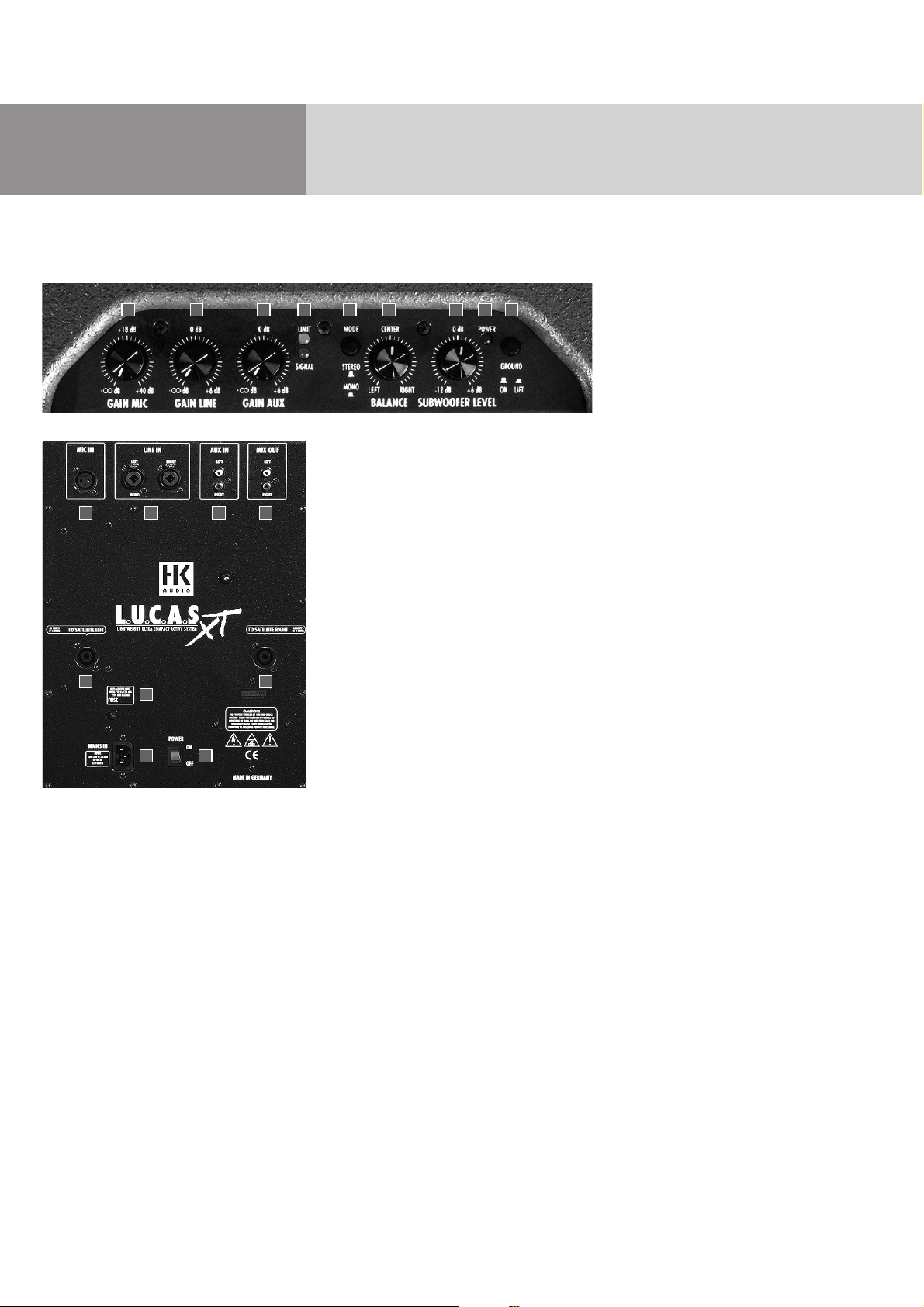
1 L.U.C.A.S
®
XT’s Control Features
1 Gain Mic
Twist this knob to adjust the microphone level.
Note: You can adjust the microphone and line or
auxiliary inputs separately and mix them as desired.
2 Gain Line
This knob adjusts power amp gain to match input
signal levels. In the event that distortion becomes
audible, the incoming signal level is too high. Simply
back off this knob.
3 Gain Aux
This knob adjusts power amp gain to match input
signal levels. In the event that distortion becomes
audible, the incoming signal level is too high. Simply
back off this knob.
4 Limiter Status LEDs
These dual-color LEDs indicate the operating status
of the multi-band limiter. Green = incoming signal,
limiters inactive; yellow = limiter occasionally activated;
red = limiters operating continuously.
5 Mode
If you have just a mono signal available, patch it to
the left input of the Line In or Aux In circuits. Set the
Mode switch to Mono. When you do this, the system
outputs the monaural input signal on both sides (the
left and right).
6 Balance
Use this knob to adjust the relative levels of the left
and right channels.
7 Subwoofer Level
Use this knob to adjust the relative volume of the
subwoofer.
8 Power On LED
This LED lights up when the system is plugged into a
mains power supply and the Power switch (see rear
panel) is set to On.
9 Ground
Ground lift switch for separating the signal and
chassis ground when you encounter problems with
humming noises. The ground circuit is severed when
you press the button in.
Caution: Never tape over the plug’s ground terminal
– this endangers lives!
10 Mic In
You may plug a microphone directly into this electronically balanced XLR input. (pin 1= ground, 2= +, 3= -).
11 Line In Left/Right
This electronically balanced XLR input is designed
to take mixer signals (pin 1= ground, 2= +, 3= -).
You can also use cables equipped with 1/4" TRS (stereostyle) plugs (tip = +, ring = -, shield = ground).
12 Aux In
RCA connector designed to take external signal
sources such as (DJ) mixing consoles and CD players.
13 Mix Out
Master output for patching Line, Aux In and Mic In
signals through to other devices such as tape decks
and MD recorders or another L.U.C.A.S
®
XT system.
14 To Satellite Left/Right
Connect these Speakon
®
outputs to L.U.C.A.S®XT’s
satellite speakers.
15 Fuse
Mains fuse. In the event of a malfunction, this
fuse will blow, severing the connection between
L.U.C.A.S®XT and the mains power supply in order
to protect the system from harm. Replace only with
another fuse of the same type and rating as specified.
16 Mains Input
Use the factory-included power cord to connect this
socket to a mains outlet.
1 2 3 4 5 6 7 8 9
10 11 12 13
14
15
16 17
14
Page 6
7
English
Caution! Make sure the local mains voltage matches
the voltage specified on the rear panel of L.U.C.A.S
®
XT.
If you connect the L.U.C.A.S
®
XT system to the wrong
mains voltage, you can damage its electronic
components.
17 Power Switch
L.U.C.A.S
®
XT on/off switch. The light within the
switch will glow red to indicate that it is powered up.
2 Setting Up and Connecting
L.U.C.A.S
®
XT
Line In
Connect cables carrying signals from your mixer
(master left/right, line out, or a similar circuit) to the
balanced Input sockets using a cord equipped with
standard XLR microphone connectors or 1/4" plugs.
Make sure the XLR connectors have the following pin
assignments: 1= ground, 2= +, 3= -. You can also use
cables equipped with 1/4" TRS (stereo-style) plugs
(tip = +, ring = -, shield = ground).
Aux In
Connect cables carrying signals from your DJ mixer,
CD player or tape deck (CD out, tape out, or similar
output) to Aux In using a cable equipped with RCA
connectors.
Mic In
If you want to connect a microphone directly to
L.U.C.A.S
®
XT without going into a mixer first, plug it
into the balanced Mic In socket. Use a standard XLR
microphone cable for this. Make sure the XLR connectors are wired with pin 2 hot (pin assignments:
1 = ground, 2 = +, 3 = -).
Satellite Left/ Right
Connect the L.U.C.A.S
®
XT system’s satellite speakers
to the Satellite Left and Satellite Right outputs. Use
Speakon
®
loudspeaker cables with wire cross-sections
of at least 2 x 1.5 mm2to do this.
Caution: The Satellite Left and Satellite Right outputs
are designed for a nominal impedance of four ohms.
Under no circumstances may the impedance fall
below this value, otherwise the power amp may
suffer serious damage! Use L.U.C.A.S
®
XT satellite
loudspeakers only!
Note: This system’s components were matched
and tuned for superior audio performance in the
configuration described herein. Do not set up or
use this system in any other configuration. If you use
satellites other than those that ship with the system,
this could degrade the system’s sound or even damage
the power amp.
An electrical connection between the cord and input
jack is not established until the Speakon
®
connector
locks into place. Turn the Speakon connector
clockwise until it engages.
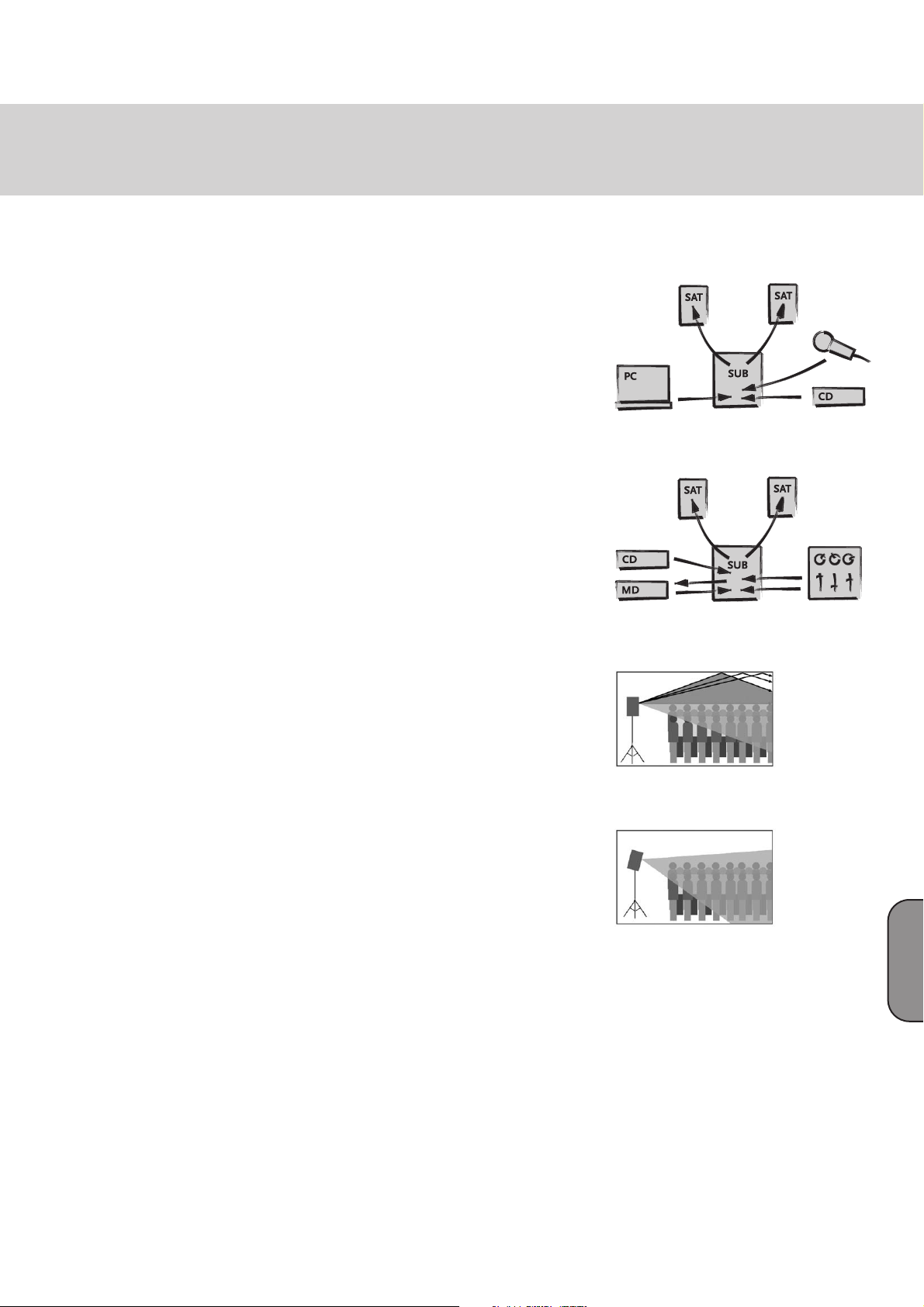
3 Mounting the Satellites
on Speaker Stands
The newly developed, integrated MicroTilt™ pole
mount enables far more efficient use of sound energy.
Offering a 10° angle of tilt, it lets you line up cabinets
so that they face the audience rather than towards
walls and ceilings. Troublesome ceiling reflections
are minimized, and you end up with a focused sound
that is clear and punchy. Cabinets are stabilized
at their center of gravity - no wobbling, tilting, or
unintentional turning. What’s more, the HK AUDIO
®
MicroTilt™ collar can accept microphone stands.
The maximum attainable height with microphone
stands is 165 to 170 cm (about 5 1/2 feet), which is
often sufficient for smaller events or presentations
at which the audience is seated.
The HK AUDIO
®
L.U.C.A.S®XT Add-On Package is
highly recommended for musical performances or
presentations requiring coverage of greater areas
and distance (10 to 15 meters / 30 to 50 feet). This
kit consists of two stands (extendable to a height of
205 cm / 6’ 8"), a practical gig bag for easy transport
and two loudspeaker cables for connecting the
satellites to the subwoofer.
Presentation setup
Live performance setup
That was then: Up to 50% of the
sound energy was wasted
HK AUDIO®MicroTilt™: Full
utilization of sound energy
Page 7

L.U.C.A.S XT Manual 2.0
4 Operating the System
First, make sure the Power On switch is set to the
Off position.
Caution! Connect the power cable only after you have
made absolutely sure that the local mains voltage
matches the voltage specified on the device. If you
connect the system to the wrong mains voltage, you
can easily damage the electronic components of the
L.U.C.A.S
®
XT system.
Gain Line In, Aux In, Mic In
Turn all Gain knobs (Gain Line, Gain Mic and Gain
Aux) all the way down (counterclockwise as far as
they will go).
Before you power L.U.C.A.S
®
XT up, make sure that all
connected peripheral components are switched on
first. Your mixer, and all signal sources connected to
it such as keyboards, instrument amps, effects and
so forth, should be switched on first.
The L.U.C.A.S
®
XT system should always be switched
on last. Again, that means after you switch on all
connected devices. After you power the system up by
activating the On/Off switch (it will light up red
when it is set to On and getting mains power),
set the Gain Line knob to the center or 12 o’clock
position (= 0 dBV).
This is the preferred level if you have connected
a mixer to L.U.C.A.S
®
XT. If you connect a CD player
or a keyboard directly to the system, turn the Gain
Line knob clockwise all the way to the far right to
achieve maximum volume.
Note: Many DJ mixing desks are equipped with RCAformat outputs only. If you want to employ this type
of mixer, use either an RCA/XLR adapter (or RCA/1/4"
jack adapter) and plug it into the Line In port,
or connect the mixer to Aux In using a standard
RCA connector-equipped cord.
If you want to plug a CD player directly into the system,
use Aux In to do this. Depending on signal level, you
can turn the Gain Aux knob all the way to the right in
order to achieve maximum volume.
5 Settings
Gain Mic Knob
Use this knob to adjust microphone level.
Note: You can adjust the microphone and line inputs
separately and mix them as desired. In the event of
audible distortion or saturated signals, back off the
Gain Mic knob.
Gain Line Knob
If you hear distortion or saturated signals, first check
the signal sources and, if possible, reduce the output
signal level there. If the signal that you are routing to
the L.U.C.A.S
®
XT system cannot be adjusted at the
source, adjust the power amp by backing off the
Gain Line knob.
Gain Aux Knob
Use this knob to adjust the level of the Aux In channel.
Note: You can adjust Aux In and Line In separately
and mix them as desired. In the event of audible
distortion or saturated signals, back off the
Gain Aux knob.
Mode
If you have just a mono signal available, patch it to
the left input of the Line In or Aux In circuits. Set
the Mode switch to Mono. This way the system can
output the monaural input signal on both left and
right sides.
Balance
Use the Balance knob to adjust the relative levels of
the left and right channels. The two sides’ volume
levels are equal when the knob is set to the center
position.
Subwoofer Level
When this knob is set to the center position, the
volume of the subwoofer is perfectly balanced with
the levels of the satellites so that the audience
is treated to a homogeneous sound with an even
distribution of bottom-end and top-end (satellite)
signals. If you want to boost or cut the bass frequencies, simply turn the Subwoofer Level knob to the left
(down to -12 dB) or right (up to +6 dB).
Page 8

9
English
Ground Lift Switch
If you encounter low frequency hum, try activating
the Ground Lift switch, which severs the chassis
earth circuit. If this doesn’t eliminate the problem,
check all cables connected to the L.U.C.A.S
®
XT system
and all signals routed to the mixer until you pinpoint
the problem.
Caution: Never tape over the plug’s ground terminal
– this endangers lives!
6 L.U.C.A.S®XT Accessories
L.U.C.A.S®XT Add-On Package
This complete accessory kit for L.U.C.A.S
®
XT consists
of two aluminum speaker stands, one gig bag and
two seven-meter speaker cables.
Item number: 191813
L.U.C.A.S
®
XT Roller Bag
A convenient and secure transportation solution for
the L.U.C.A.S
®
XT system, this roller bag offers rugged upholstered bags designed to protect the subwoofer and satellites. Simply strap the bag containing
the satellites to the subwoofer and transport the
entire PA system easily on the built-in casters. The
roller bag also offers several practical compartments,
perfect for storing cables, microphones and even
small mixers.
Item number: 191823
L.U.C.A.S
®
XT Wall Mount
Wall-mounting bracket for L.U.C.A.S
®
XT satellite
speakers.
Item number: 191803
To learn more about original HK AUDIO
®
accessories,
talk to an HK AUDIO
®
dealer near you or visit
www
.hkaudio.com
7 Tips and Tricks
1 Don’t expose electronic circuitry to moisture! When
you set the system up outdoors, be sure to protect
it against rain. Keep soft drinks, beer or any other
liquids well away from the cabinets to protect their
electronic components from short circuits.
2 L.U.C.A.S
®
XT delivers optimum sound when you
provide it with optimum input signals! Noise such
as hum is generally caused by defective cables, the
wrong type of cables, or unbalanced signals routed
into the mixing console. Check all signal and mains
cables.
3 Prevent distortion! Not only is it unpleasant to
the ears of your audience, it can also endanger
your equipment. Make sure all components that
are connected directly and indirectly to the
L.U.C.A.S
®
XT system have sufficient power ratings,
and that they don’t distort from running at their
respective limits. Provide an undistorted signal
to the system. If you send a distorted signal,
backing off the Gain knob won’t help clean it up.
Keep it clean!
4 Avoid ground loops! Even if the signal-carrying
circuit is balanced, redundant ground circuits in
a single audio system may generate undesirable
humming. For example, you may encounter a
ground loop when the mixer is grounded via a
mains cord that isn’t connected to the same mains
circuit as the L.U.C.A.S
®
XT system. To prevent this
problem, always be sure to connect L.U.C.A.S
®
XT
and the mixing console to the same electrical circuit.
(Same phase!) If your equipment hums despite
this precaution, the Ground Lift switch can be a
great help.
Caution: Never tape over the plug’s ground terminal
– this endangers lives!
L.U.C.A.S® XT Roller Bag
L.U.C.A.S®XT Add On Package
L.U.C.A.S®XT Add On Package
Page 9

L.U.C.A.S XT Manual 2.0
8 Troubleshooting
The Power On LED and the mains switch do not
light up red after you switch the system on.
• Check if the power cord is plugged into the
Mains Input.
• Check if the mains power supply is actually
providing current.
• Check if L.U.C.A.S
®
XT’s fuse is defective. Replace
only with another fuse of the same type and rating
as specified.
The Power On LED and the Power switch light up
red, but no sound is coming from the cabinets.
• Check the cables that you connected to the Line In,
Mic In and Aux ports.
• Check if the signal sources (mixer, keyboard,
CD player) are on.
• Are the Gain knobs turned up?
• Check the loudspeaker cables for damage.
• Check if the Speakon
®
connectors plugged into the
Satellite Left and Satellite Right sockets are engaged
all the way (rotated fully to the right). Only then
will an electrical connection be established.
The subwoofer’s bass response sounds thin or weak.
• Check the setting of the Subwoofer Level knob.
Adjust the volume of the subwoofer using the
Subwoofer Level knob until you get the kind of
bottom end you want to hear.
The signal sounds distorted.
• Check the LED displays on your mixer. They should
not be constantly in the red. If necessary, back off
the volume at the mixer.
• If the LED displays on your mixer are in the green,
turn down the L.U.C.A.S
®
XT’s Gain knob (Line In
or Aux In).
• Observe the LEDs of the Limiter Status displays on
L.U.C.A.S
®
XT’s control panel. If the yellow LED lights
up continuously, the integrated protective functions
are working at full capacity. In this instance, do not
turn the volume level up any higher.
Annoying hum
• Check the cables that you are using to connect the
signal source to L.U.C.A.S
®
XT. Replace damaged cables.
• If you cannot pinpoint the cause of the hum, press
the Ground Lift switch. This should remedy the
problem in most cases.
Page 10

11
English
9 Technical Specifications
L.U.C.A.S®XT Subwoofer
Inputs/Outputs:
Line In: XLR female, 1/4" combination jack
(pin 1= ground; 2= +, 3= -) electronically balanced &
floating
Aux In: RCA connector unbalanced
Mic In: XLR female (pin 1 = ground; 2 = +, 3 = -)
electronically balanced & floating
Sum Out, Master Out: RCA connector unbalanced
Output level: +4 dBV peak
Satellite speaker outs: Speakon®(pin 1+ = +, 1- = -)
Amplifier and loudspeakers Subwoofer
Subwoofer power output: 250 W / 3 ohms @ 0.3 % THD
Satellite power output: 2x 60 W / 4 ohms @ 0,3 % THD
Protection circuits: HK AUDIO
®
Multi Band Limiter,
Subsonic Filter
Low-frequency loudspeaker: 1x 10" HK AUDIO
®
Custom
Impedance: 3 ohms
Active crossover: 90 Hz; 24 dB/octave,
Frequency response: 43 Hz to 92 Hz, +/-3dB
34 Hz to 140 Hz, -10dB
Sound pressure level 1W/1m, half-space: 97 dB
Max. sound pressure level/1m, half-space: 117 dB @
10% THD
Weight: 16 kg/ 35.2 lbs.
Dimensions (WxHxD): 32 cm x 41 cm x 46,5 cm
(12 5/8" x 16 1/8" x 18 3/8")
L.U.C.A.S
®
XT Satellite
Loudspeaker input: Speakon
®
NL 4 (pin 1+ = +, 1- = -)
Mid-range loudspeaker: 1x 6.5" HK AUDIO
®
Custom
Tweeter: 1x 1" Dome Tweeter
Mounting collar: HK AUDIO
®
MicroTilt™, 15 mm
Directivity: 80° x 50°
Impedance: 4 ohms
Nominal power handling capacity: 60 W RMS
Crossover frequency (passive, internal): 3 kHz;
12 dB/octave
Frequency response (via active crossover): 92 Hz to
21 kHz, +/-3dB; 85 Hz to 23 kHz, -10dB
Sound pressure level 1W/1m, half-space: 97 dB
Max. sound pressure level/1m, half-space: 115 dB
@ 10% THD
Weight: 4.5 kg/9.9 lbs.
Dimensions (WxHxD): 18.5 cm x 27.5 cm x 21.5 cm
(7 1/4" x 10 7/8" x 8 1/2")
General electrical data:
Protection class 1 (protectively earthed)
Max. current consumption: 1.6 A (230 V), 3.15 A (117 V),
3.15 A (100 V)
Max. power consumption: 370 VA
Mains voltage range: ± 10%
Ambient operating temperature: -10° C to +35° C
Page 11
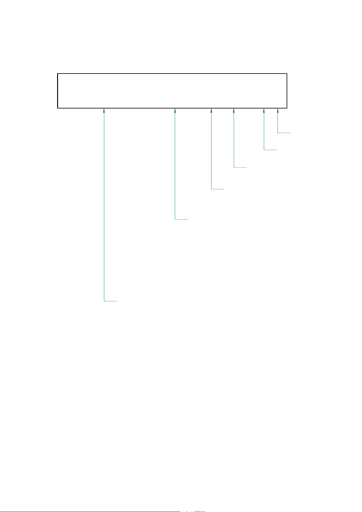
DRAWING-NUMBERS
EXAMPLE
HK0106-EX-R01-1A
PROJECT-NR.:
HK = HK AUDIO
HU = HUGHES&KETTNER
MP = MINDPRINT
CHARACTER:
BL = SHEET METAL / BLECH
EX = EXPLODED DRAWING / EXPLOSIONSZEICHNUNG
HZ = CABINET / HOLZGEHÄUSE
KU = PLASTIC / KUNSTSTOFF
LP = PCB / LEITERPLATTEN
SO = MISCELLANEOUS / SONSTIGES
SP = SCHEMATIC / SCHALTPLÄNE
TR = TRANSFORMER / TRANSFORMATOR
GK = WIRING DIAGRAM / GERÄTEVERKABELUNG
DEPARTMENT:
R = R&D
SERIAL NUMBER
VERSION
REVISION
Page 12
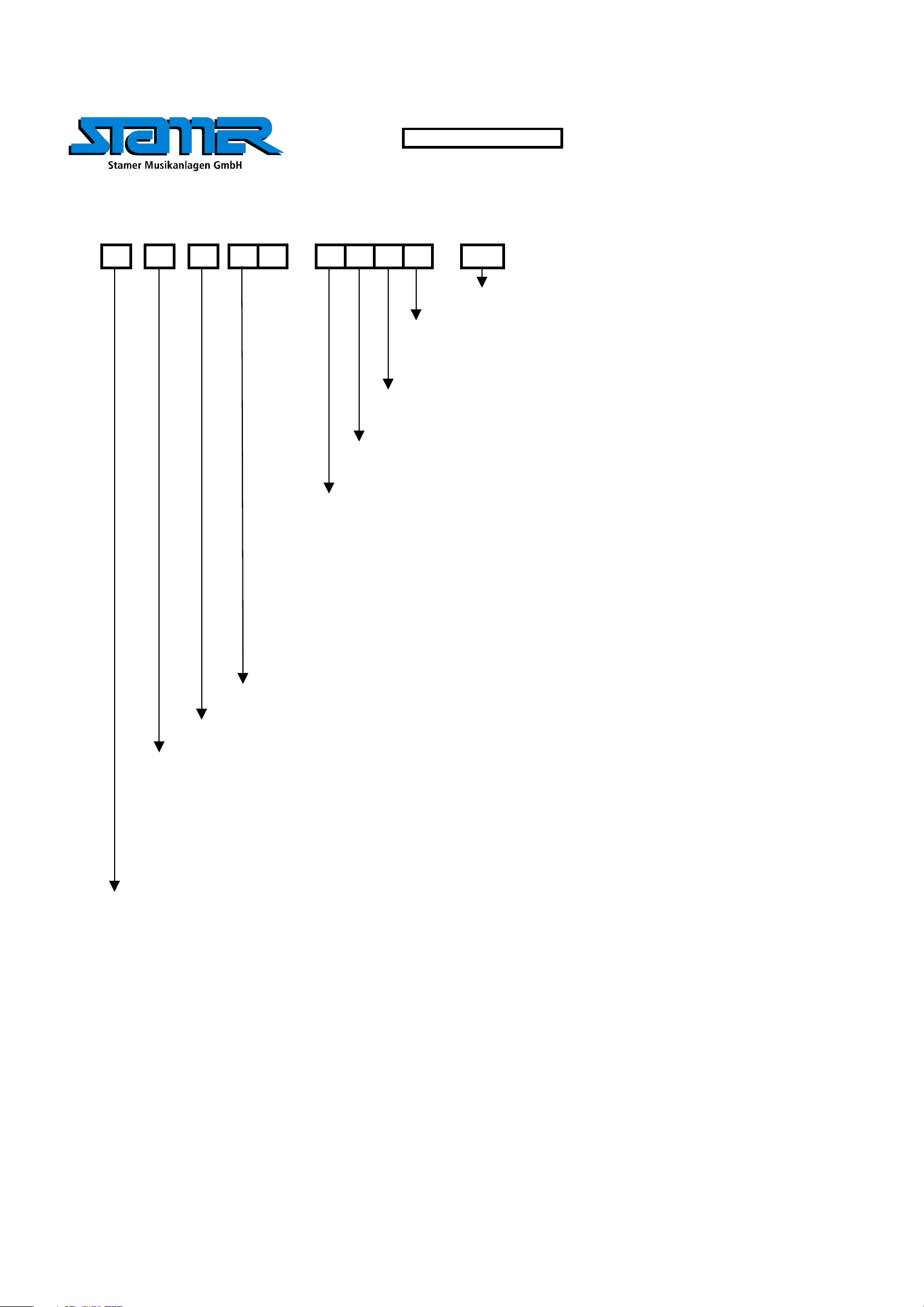
Stand
W
Y
r
Standard for single wire confection.
16 B 150 638 I - 485 W Z I 1015
style 1015 according UL specifications
I = completely insulated with black shrinktube or appropriate sleeve
IT = partly insulated; only crimp connection insulated.
no marking = without insulation
Z = with additional junction
no marking = without additional junction
W = angled faston
no marking = straight faston
17. Jun 04
Faston connector brass tin-plated DIN 46245
638 = 6,3 * 0,8 [mm]
488 = 4,8 * 0,8 [mm]
485 = 4,8 * 0,5 [mm]
288 = 2,8 * 0,8 [mm]
285 = 2,8 * 0,5 [mm]
abiso = 5mm bared and tin-plated (teilabzug)
text for special constructions, (for example. 4mm ringshaped faston)
the larger faston connector always mentioned at first. (Nathan drawing number controlling)
lenght in mm within a 50 mm raster
colour
B = black (phase conductor)
R = red
BR = brown
BL = blue (neutral conductor)
= white
G = yellow-green (ground bonding/ earthing connection)
if fully insulated (I) insulation with blue shrinktube
if partly insulated (IT) use IF 602 485 .
if fully insulated (I) insulation with blue shrinktube
if partly insulated (IT) use IF 602 485
cross section
16 = AWG 16 (prefered usage)
Q1.5 = H07VK 1,5mm² (prefered usage)
wire designation:
P + lfd Nr. = AWG single wire black, red, blue, brown or white
E + lfd Nr. = AWG single wire green- yellow
L + lfd N
FQL + lfd Nr. = crossover wiring H07VK
Regarding special wirings like wiring harness or similar, drawings will be prepared and appropriate
. = twisted AWG double wire, lenght specification always in twisted condition
drawing numbers will be stored in the article archive.
Page 13

Confidential, for authorized service technicians only! Do not disclose
this information to or share these documents with third parties.
TECHNICAL SERVICE:
Stamer Musikanlagen GmbH • Magdeburger Str. 8 • 66606 St.Wendel • Germany
Music & Sales P.E. GmbH • Leipziger Str. 3 • 66606 St.Wendel • Germany
Service Documents
HK2001
L.U.C.A.S
XT
SAT/SUB
Page 14

4E 972008
6 E 974216
11 E 994151
3 E 520071
ÄNDERUNG
INDEX
Bezugslinien ergänzt
1B
6
2 E 400146
1E 1101
8 E 976015
7E 974322
10E 994150
TITEL:
LUCAS XT HK2001
LUCAS XT-TOP
GESAMT
OBERFLÄCHE:
VERSION:
AM:
28.01.03
AM:
07.02.03
REVISION:
BLATT:
B
1/2
BLÄTTER
1
ZEICHNER
C. Loris
9 E 976118
5E 974094
66606 St. Wendel / Germany
ZEICHNUNGS-NR.:
ERSTELLT VON:
GEPRÜFT/
FREIGEGEBEN VON:
WERKSTOFF:
DATEINAME:
HK2001-EX-R02-1B
C. LORIS
KLAUS BIRSTER
HK2001-EX-R02-1B-TOP-GESAMT
Page 15

ÄNDERUNG
INDEX
Bezugslinien ergänzt
1B
ZEICHNER
C. Loris
66606 St. Wendel / Germany
ZEICHNUNGS-NR.:
ERSTELLT VON:
GEPRÜFT/
FREIGEGEBEN VON:
WERKSTOFF:
DATEINAME:
HK2001-EX-R02-1B
C. LORIS
KLAUS BIRSTER
HK2001-EX-R02-1B-TOP-GESAMT
TITEL:
LUCAS XT HK2001
LUCAS XT-TOP
GESAMT
OBERFLÄCHE:
VERSION:
AM:
28.01.03
AM:
07.02.03
REVISION:
BLATT:
B
2/2
BLÄTTER
1
Page 16

1 E 970335
ÄNDERUNG
INDEX
QUADRATMETER GEÄNDERT
1B
ZEICHNER
C. LORIS
3E 974158
4980124
66606 St. Wendel / Germany
ZEICHNUNGS-NR.:
ERSTELLT VON:
2 E 972009
GEPRÜFT/
FREIGEGEBEN VON:
WERKSTOFF:
DATEINAME:
HK2001-EX-R01-1B-TOP-FRONTBAUGRUPPE
SERVICE-NR.: 1101
TITEL:
LUCAS XT HK2001
LUKAS XT-TOP
FRONTBAUGRUPPE
HK2001-EX-R01-1B
C. LORIS
KLAUS BIRSTER
OBERFLÄCHE:
VERSION:
AM:
28.01.03
AM:
07.02.03
REVISION:
1
BLATT:
B
1
BLÄTTER
Page 17

66606 St. Wendel / Germany66606 St. Wendel / Germany
Zeichnungsnummer:
Erstellt von:
Geprüft /
freigegeben von:
Werkstoff:
Dateiname:
HK2001-GK-R02-1B
M. Marx
HK2001-GK-R02-1B.vlm
Titel:
HK2001 - Lucas XP Top
Verkabelungsplan
Version:
am:
06.06.2002 1
am:
21.03.2002
Oberfläche:
Revision:
1
Blatt
1
B
Blätter
Page 18

10 E 974322
3E 502096 (230V)
E 502097 (117V)
6E 974096
14 E 976097
2E 400145
E 502098 (100V)
11E 974336
15E 994149
4 E 970481
7E 974159
1E 1100
ÄNDERUNG
INDEX
Artikel-Nr. 2+3 ergänzt,
1B
Zeichnungs-Nr. aktualisiert
14
5 E 972047
9E 974314
13 E 976015
12E 976009
66606 St. Wendel / Germany
ZEICHNUNGS-NR.:
ERSTELLT VON:
GEPRÜFT/
FREIGEGEBEN VON:
WERKSTOFF:
DATEINAME:
ZEICHNER
C. Loris
8E 974194
6
TITEL:
LUCAS XT HK2001
LUCAS XT BASS
GESAMT
OBERFLÄCHE:
VERSION:
AM:
28.01.03
AM:
07.02.03
HK2001-EX-R06-1B
C. LORIS
KLAUS BIRSTER
HK2001-EX-R06-1B-BASS-GESAMT
REVISION:
1
BLATT:
B
1/2
BLÄTTER
Page 19

ÄNDERUNG
INDEX
Artikel-Nr. 2+3 ergänzt,
1B
Zeichnungs-Nr. aktualisiert
ZEICHNER
C. Loris
TITEL:
LUCAS XT HK2001
LUCAS XT BASS
66606 St. Wendel / Germany
ZEICHNUNGS-NR.:
ERSTELLT VON:
GEPRÜFT/
FREIGEGEBEN VON:
WERKSTOFF:
DATEINAME:
HK2001-EX-R06-1B
C. LORIS
KLAUS BIRSTER
HK2001-EX-R06-1B-BASS-GESAMT
GESAMT
OBERFLÄCHE:
VERSION:
AM:
28.01.03
AM:
07.02.03
REVISION:
1
BLATT:
B
2/2
BLÄTTER
Page 20

1E 970335
SERVICE-NR.: 1100
INDEX
ÄNDERUNG
ZEICHNER
2E 972042
3E 974158
TITEL:
LUCAS XT HK2001
LUCAS XT-BASS
4E 980124
66606 St. Wendel / Germany
ZEICHNUNGS-NR.:
ERSTELLT VON:
GEPRÜFT/
FREIGEGEBEN VON:
WERKSTOFF:
DATEINAME:
HK2001-EX-R04-1A
C. LORIS
KLAUS BIRSTER
HK2001-EX-R04-1A-BASS-FRONTBAUGRUPPE
FRONTBAUGRUPPE
VERSION:
AM:
21.11.02
AM:
07.02.03
OBERFLÄCHE:
REVISION:
1
BLATT:
A
1
BLÄTTER
Page 21

11 E 966044
2E 547030
1E 547030
10 E 966018
16 E 970546
15 E 970528
14 E 970517
3 E 547031
5 E 932016 (230V)
ÄNDERUNG
INDEX
Ferritringe eingesetzt,
1B
Zeichnungsnr. aktualisiert,
Artikel-Nr. 2 eingesetzt
ZEICHNER
C. Loris
9 E 958146 (230V)
4 E 930077
13 E 970516
8 E 956239
7E 952022
TITEL:
LUCAS XT HK2001
LUCAS XT-BASS
CHASSIS
OBERFLÄCHE:
VERSION:
AM:
28.01.03
AM:
07.02.03
REVISION:
1
BLATT:
B
1
BLÄTTER
6 E 950006 (230V)
12 E 970515
66606 St. Wendel / Germany
ZEICHNUNGS-NR.:
ERSTELLT VON:
GEPRÜFT/
FREIGEGEBEN VON:
WERKSTOFF:
DATEINAME:
HK2001-EX-R05-1B
C. LORIS
KLAUS BIRSTER
HK2001-EX-R05-1B-BASS-CHASSIS
Page 22

ÄNDERUNG
INDEX
Ferritringe eingesetzt,
1B
Zeichnungsnr. aktualisiert,
Artikel-Nr. 2 eingesetzt
ZEICHNER
C. Loris
TITEL:
LUCAS XT HK2001
LUCAS XT-BASS
66606 St. Wendel / Germany
ZEICHNUNGS-NR.:
ERSTELLT VON:
GEPRÜFT/
FREIGEGEBEN VON:
WERKSTOFF:
DATEINAME:
HK2001-EX-R05-1B
C. LORIS
KLAUS BIRSTER
HK2001-EX-R05-1B-BASS-CHASSIS
CHASSIS
OBERFLÄCHE:
VERSION:
AM:
28.01.03
AM:
07.02.03
REVISION:
1
BLATT:
B
1
BLÄTTER
Page 23

Nathan Nr.: 962052
Nathan Nr.: 962017
B
R
GRR
G
B
PIN 1
GB
DATUM
10.06.02 F. Sitter
ÄNDERUNG
Ersterstellung
INDEX
A
ZEICHNER
Titel:
HK2001 - L.U.C.A.S. 400
66606 St. Wendel / Germany66606 St. Wendel / Germany
Zeichnungsnummer:
Erstellt von:
Geprüft /
freigegeben von:
Werkstoff:
Dateiname:
HK2001-GK-R03-1A
F. Sitter
F. Sitter
-n/aHK2001-GK-R03-1A-Verkabelung.vlm
Preamp Wiring
Version:
am:
am:
Oberfläche:
1
10.06.2002
10.01.2002
-n/a-
Revision:
Blatt
1
A
1
Blätter
Page 24

Nathan Nr.: 962319
ICE Power
ICE250 A
Nathan Nr.: 964045
To ICE Power
YELLOW
BLUE
From ICE Power
Speaker
+
Eminence 3R 10"
-
From
Preamp
Nathan Nr.: 962332
To Top Left
BLACK
RED
Nathan Nr.: 962319
To Top Right
BLACK
RED
To ICE Power
BLACK
RED
GREENYELLOW
Nathan Nr.: 962035
connected
to chassis
WHITE
connected
to chassis
BLACK
RED
Nathan Nr.: 962184
BLACK
WHITE
Power
Switch
WHITE
RED
RED
26V
1,92A
BLUE
0V
26V
1,92A
Primary
36V
6,39A
BROWN OR
YELLOW
0V
DATUM
06.06.02
23.10.02
ÄNDERUNG
Ersterstellung
Vorstufenverbindungskabel
INDEX
A
B
ZEICHNER
F. Sitter
F. Sitter
Nathan Nr.: 962031
Titel:
HK2001 - L.U.C.A.S. 400
66606 St. Wendel / Germany66606 St. Wendel / Germany
Zeichnungsnummer:
Erstellt von:
Geprüft /
freigegeben von:
Werkstoff:
Dateiname:
HK2001-GK-R01-1A
F. Sitter
F. Sitter
-n/aHK2001-GK-R01-1B-Verkabelung.vlm
Amplifier and Power Supply Wiring
Version:
am:
am:
Oberfläche:
1
23.10.2002
23.10.2002
-n/a-
Revision:
Blatt
1
B
1
Blätter
Page 25

66
4
55
INDEX CHANGES
9
1
7
2
8
1010
TITLE:
LUCAS XT HK2001
PREAMP
3
3
RESP.
66606 St. Wendel / Germany
DRAWING-NO.:
DRAWN BY:
CHECKED BY:
MATERIAL:
FILENAME:
HK2001_LP_R01_1H
Frank Sitter 1
Fehler: Keine Referenz
HK1505_LP_R01_1A_preamp
FINISH:
VERSION:
DATE:
22.08.2007
DATE:
REVISION:
PAGE:
H1
PAGES
Page 26

INDEX CHANGES
RESP.
66606 St. Wendel / Germany
DRAWING-NO.:
DRAWN BY:
CHECKED BY:
MATERIAL:
FILENAME:
HK2001_LP_R01_1H
Frank Sitter 2
Fehler: Keine Referenz
HK1505_LP_R01_1A_preamp
TITLE:
LUCAS XT HK2001
PREAMP
FINISH:
VERSION:
DATE:
22.08.2007
DATE:
REVISION:
PAGE:
H1
PAGES
Page 27

12
6
6
7
4
4
2
INDEX CHANGES
2
1
14
999
14
5
3
14
11
TITLE:
LUCAS XT HK2001
88
10
RESP.
66606 St. Wendel / Germany
DRAWING-NO.:
DRAWN BY:
CHECKED BY:
MATERIAL:
FILENAME:
HK1901_LP_R02_1E
Frank Sitter 1
Fehler: Keine Referenz
HK1505_LP_R02_1A_poweramp
POWERAMP & POWERSUPPLY
FINISH:
VERSION:
DATE:
22.08.2007
DATE:
REVISION:
PAGE:
E1
PAGES
Page 28

INDEX CHANGES
RESP.
66606 St. Wendel / Germany
DRAWING-NO.:
DRAWN BY:
CHECKED BY:
MATERIAL:
FILENAME:
HK1901_LP_R02_1E
Frank Sitter 2
Fehler: Keine Referenz
HK1505_LP_R02_1A_poweramp
TITLE:
LUCAS XT HK2001
POWERAMP & POWERSUPPLY
VERSION:
DATE:
22.08.2007
DATE:
FINISH:
REVISION:
PAGE:
E1
PAGES
Page 29

CAM Products 2000(TM):
Page 30

4321
FilterRight
D
HK2001-SP-R01-1H-05FilterRight.Sch
+15V
GND
-15V
To Out Right
To Filter Right
D
Input
C
B
A
All rights reserved. No part of this schematic may be reproduced, stored in a retrieval system, transmitted in any form or
by any means, electronic, mechanical, photocopying, recording or otherwise, without the prior permission of the author.
HK2001-SP-R01-1H-01Input.Sch +15V
1 2 3 4
Gain
HK2001-SP-R01-1H-02Gain.Sch
To Filter Right
To Bass
To Filter Left
GND
-15V
FilterBass
HK2001-SP-R01-1H-03FilterBass .Sch
+15V
GND
-15V
To Bass
FilterLeft
HK2001-SP-R01-1H-04FilterLeft.Sch
To Filter Left
+15V
GND
-15V
66606 St. Wendel / Germany
Number: Version: Revision:
Drawn by: Date:
Material: Surface:
Filename: HK2001-SP-R01-1H.Sch
To Out RightTo Out Left
To Out Left
F.Sitter
Name geprüft
Title:
HK2001 Preamp
Date:
1HK02001-SP-R01 H
15.12.2004
01.01.2001
Page:
6Checked by:
1
Pages
C
B
A
Page 31

+12Vi +12Vi
D
LINE IN
C
B
LINE IN
A
All rights reserved. No part of this schematic may be reproduced, stored in a retrieval system, transmitted in any form or by any means, electronic, mechanical, photocopying, recording or otherwise, without the prior permission of the author. Filename: HK2001-SP-R01-1H-01Input.Sch
Input Left/Mono
J3
NCJ9FI-H
*
Input Right
J2
NCJ9FI-H
*
AUX IN
1 2 3 4 5 6 7 8
CINCH--2L2P-1
AUX IN
CINCH--2L2P-1
2
3
1
4
5
6
7
8
9
10
C8
10u/63V
J4B
2
3
1
4
5
6
7
8
9
10
C11
10u/63V
J4A
C9
10u/63V
C10
10u/63V
R3
47R/1W
C2
10n/63V_RM5
R23
4K7
C6
10u/63V
C7
10u/63V
R2
47R/1W
C3
10n/63V_RM5
R24
4K7
R13
2K2
R14
2K2
C46
100pF/100V-K
R8
2K2
R9
2K2
C47
100pF/100V-K
100pF/100V-K
+12Vi
1N4148
-12Vi
R12
22K
100pF/100V-K
+12Vi
1N4148
-12Vi
R18
22K
D5
D10
1N4148
D15
D16
1N4148
C14
-12Vi -12Vi
R41
47K
5
6
+12Vi +12Vi
C13
-12Vi
R42
47K
3
2
D11
D13
1N4148
1N4148
D12
D14
1N4148
1N4148
U2B
MC33079P(MOT)
+
-
R15
22K
D6
1N4148D81N4148
D7
1N4148D91N4148
-12Vi
+12Vi
U2A
411
MC33079P(MOT)
+
VCC
-
VEE
-12Vi
R19
22K
R16
11K
+12Vi
U3A
MC33078P(MOT)
84
3
VCC
+
-
VEE
-12Vi
R17
11K
C17
47pF/100V-K
U3B
MC33078P(MOT)
+
-
R11
11K
C16
47pF/100V-K
1
+12Vi +12Vi
D1
R4
2K2
R5
2K2
C12
100pF/100V-K
R36
10K
R45
10K
1N4148D31N4148
D2
1N4148D41N4148
-12Vi -12Vi
10
9
R46
10K
12
13
R81
10K
U2C
MC33079P(MOT)
+
-
C44
47pF/100V-K
U2D
MC33079P(MOT)
+
-
C45
47pF/100V-K
66606 St. Wendel / Germany
Number: Version: Revision:
Drawn by: Date:
Checked by:
Material: Surface:
MICROPHONE
J1
XLR/F-RX90702
7
C42
+
2u2/25V-T
C70
100n/63V_RM5
5
6
U1B
MC33078P(MOT)
+
-
C43
+
2u2/25V-T
C41
100n/63V_RM5
7
2
3
1
C1
10n/63V_RM5
C4
10u/63V
C5
10u/63V
R1
47R/1W
-12Vi+12Vi
R6
10K
8
14
Frank Sitter
Name
3
2
R7
10K
U1A
MC33078P(MOT)
+12Vi
84
VCC
+
-
VEE
-12Vi
C15
47pF/100V-K
R88
47R
R89
47R
2
7
R10
11K
5
6
1
Chinch Left
XLR Left
XLR Right
Chinch Right
1
J5A
CINCH--2L2P-1
J5B
CINCH--2L2P-1
Title:
HK2001 - Preamp - Input
+12Vi
-12Vi
Rec Out Left
Rec Out Right
Rec Out Left
1HK2001-SP-R01 H
15.12.2004
01.01.2001
Date:
87654321
12
11
10
9
8
7
6
5
4
3
2
1
Rec Out Right
JP1
SL-12P12X1W
2
Page:
6
Pages
D
C
B
A
Page 32

87654321
J6
12
+12V
11
-12V
SB-12P12X1
10
9
8
7
6
5
4
3
2
1
Rec Left
Rec Right
Cinch Left
XLR Left
XLR Right
Cinch Right
R20
4K7
D
C
B
LR
BR5
0R0
BR6
0R0
BR7
0R0
BR8
0R0
P1
RK16-B10K
C18
22u/50V
R21
470R
P2A
RK16-B10K-ST-CC
L1 R1
P6B
L2 R2
RK16-B10K-ST-CC
P2B
L2 R2
RK16-B10K-ST-CC
P6A
L1 R1
RK16-B10K-ST-CC
12
+
13
-
C19
47pF/100V-K
R22
15K
C25
22u/50V
C53
22u/50V
C51
22u/50V
C54
22u/50V
U9D
MC33079P(MOT)
R90
10K NA
BR1
0R0
NA
R29
15K
BR2
0R0
NA
R30
15K
R91
10K NA
BR3
0R0
NA
R34
15K
BR4
0R0
NA
R31
15K
R25
14
10K
R26
10K
P4B
RK16-B100K-ST-CC
*
L2 R2
P4A
RK16-B100K-ST-CC
10
9
12
13
L1R1
C26
+
2u2/25V-T
C59
+
2u2/25V-T
U4C
MC33079P(MOT)
+
-
R47
22K
C20
47pF/100V-K
C52
22u/50V
U4D
MC33079P(MOT)
+
-
R48
22K
C21
47pF/100V-K
C61
22u/50V
8
14
C27
+
2u2/25V-T
C60
+
2u2/25V-T
To Filter Left
SW2A
SW2B
23
54
R50
R49
820R
820R
C24
220n/63V_RM5
L RP3RK16-B10K-CC
R84
1K5
+12V
411
+
VCC
1
-
VEE
-12V
To Filter Right
R85
100K
R86
8K2
5
6
U4B
MC33079P(MOT)
+
-
R80
10K
C38
47pF/100V-K
7
To Bass
1
6
PBN-S2A3.5NIL-A-AG
U4A
MC33079P(MOT)
-12V+12V
-12V+12V
3
2
D
C
B
+12V
A
All rights reserved. No part of this schematic may be reproduced, stored in a retrieval system, transmitted in any form or by any means, electronic, mechanical, photocopying, recording or otherwise, without the prior permission of the author. Filename: HK2001-SP-R01-1H-02Gain.Sch
1 2 3 4 5 6 7 8
-12V
+15V
-15V
GND
66606 St. Wendel / Germany
Number: Version: Revision:
Frank Sitter
Drawn by: Date:
Name
Checked by:
Material: Surface:
Title:
HK2001 - Preamp - Gain
1HK2001-SP-R01 H
15.12.2004
01.01.2001
Date:
Page:
6
A
3
Pages
Page 33

87654321
D
C
B
To Filter Right
R37
10K
R127
27K
R72
C48
6K2
22n/63V_RM5
R243
68K
MC33079P(MOT)
-12V
2
-
3
+
4 11
+12V
U5A
VCCVEE
22n/63V_RM5
1
R255
39K
R38
10K
C49
12
13
R256
47K
NA
R73
15K
+
-
R271
10K
C22
47pF/100V-K
R129
24K
C50
6n8/63V_RM5
R244
39K
6
5
U6D
MC33079P(MOT)
14
U5B
MC33079P(MOT)
-
+
C139
220n/63V_RM5
6n8/63V_RM5
7
R63
5K6
C62
R257
R258
47K
20K
NA
C140
220n/63V_RM5
R74
2K2
R251
6K8
10
9
R131
33K
C63
4n7/63V_RM5
R245
47K
U5C
MC33079P(MOT)
9
-
10
+
U6C
MC33079P(MOT)
+
-
8
4n7/63V_RM5
8
R259
47K
NA
C141
150n/63V_RM5
C64
R75
3K3
R260
22K
C142
150n/63V_RM5
R64
2K7
R238
36K
C65
2n2/63V_RM5
13
12
R252
33K
5
6
R246
47K
U5D
MC33079P(MOT)
-
+
U6B
MC33079P(MOT)
+
-
2n2/63V_RM5
14
7
C66
R261
47K
NA
15n/63V_RM5
C147
NA
R92
12K
R262
27K
C39
2n2/63V
6n8/63V_RM5
R273
1K8
NA
C149
NA
+12V
U6A
MC33079P(MOT)
411
3
VCC
+
2
R43
12K
R51
10K
-
VEE
-12V
R53
10K
R52
10K
NA
R68
1
47R
To Out Right
D
C
B
C56
100n/63V_RM5
NA
A
All rights reserved. No part of this schematic may be reproduced, stored in a retrieval system, transmitted in any form or by any means, electronic, mechanical, photocopying, recording or otherwise, without the prior permission of the author. Filename: HK2001-SP-R01-1H-05FilterRight.Sch
1 2 3 4 5 6 7 8
+12V
-12V
+15V
-15V
GND
66606 St. Wendel / Germany
Number: Version: Revision:
Frank Sitter
Drawn by: Date:
Name
Checked by:
Material: Surface:
Title:
HK2001 - Preamp - FilterRight
1HK2001-SP-R01 H
15.12.2004
01.01.2001
Date:
Page:
6
A
5
Pages
Page 34

87654321
D
R58
+12V
R57
39K
Limit Bass
JP4
3
R
2
G
1
B
JST-B03B-EH-A
Limit Right
JP5
3
R
2
G
1
B
JST-B03B-EH-A
Limit Left
JP6
3
R
2
G
1
B
JST-B03B-EH-A
5K6
R70
20K
To Bass
C
B
C28
220n/63V_RM5
C29
220n/63V_RM5
3
2
D17
1N4148
D18
1N4148
D19
1N4148
U9A
411
VCC
+
-
VEE
-12V
MC33079P(MOT)
R71
2K0
1
D20
1N4148
D21
1N4148
D22
1N4148
R59
11K
R61
4K7
LD2
L-1503EB/2-GREEN-YELLOW
220n/63V_RM5
C30
150n/63V_RM5
C31
U9B
MC33079P(MOT)
5
+
6
-
R60
7
12K
R87
-12V
330R
R35
47R/2W
C55
47n/250V_RM5
SW1A
2 3
5 4
PBN-S2A3.5NIL-A-AG
R62
12K
D23
BZX55V_6V2
1
6
330n/63V_RM5
C32
56n/63V_RM5
LD1
L-1503CB/1-RED
C33
U9C
MC33079P(MOT)
10
+
9
-
Z1
HALTEBOLZEN-LG
Z2
HALTEBOLZEN-LG
Z3
HALTEBOLZEN-LG
Z4
HALTEBOLZEN-LG
Z5
HALTEBOLZEN-LG
R67
47R
8
C35
100p/100V-K
C37
100p/100V-K
BR10
0R0
HO3
DK-R70-B32
HO1
NDK-R0-B40
HO7
NDK-R0-B40
-12V+12V
BR12
0R0
BR11
-12V IN
10
W1
AWG24-10-2.54
BR9
0R0
+12V IN
To Out Left
0R0
0R0
BR13
BASS OUT
LEFT OUT
HO4
DK-R70-B32
HO2
NDK-R0-B40
To Out Right
0R0
BR14
RIGHT OUT
123456789
C34
100p/100V-K
C36
100p/100V-K
C58
100p/100V-K
D
C
B
A
All rights reserved. No part of this schematic may be reproduced, stored in a retrieval system, transmitted in any form or by any means, electronic, mechanical, photocopying, recording or otherwise, without the prior permission of the author. Filename: HK2001-SP-R01-1H-03FilterBass .Sch
1 2 3 4 5 6 7 8
+12V
-12V
+15V
-15V
GND
66606 St. Wendel / Germany
Number: Version: Revision:
Frank Sitter
Drawn by: Date:
Name
Checked by:
Material: Surface:
Title:
HK2001 - Preamp - FilterBass
1HK2001-SP-R01 H
15.12.2004
01.01.2001
Date:
Page:
6
A
6
Pages
Page 35

87654321
D
C
B
To Filter Left
R39
10K
R76
6K2
R239
27K
C67
22n/63V_RM5
2
3
R247
68K
MC33079P(MOT)
-12V
-
+
4 11
+12V
VCCVEE
U7A
22n/63V_RM5
1
R263
39K
R40
10K
C68
12
13
R77
15K
R264
47K
NA
U8D
MC33079P(MOT)
+
-
R272
10K
C23
47pF/100V-K
R240
24K
C69
6n8/63V_RM5
6
5
14
R248
39K
U7B
MC33079P(MOT)
-
+
C143
220n/63V_RM5
R241
33K
R78
C71
6n8/63V_RM5
7
R265
R266
47K
20K
NA
C144
220n/63V_RM5
R65
5K6 R66
C73
2K2
4n7/63V_RM5
R249
47K
U7C
MC33079P(MOT)
9
-
10
+
R253
6K8 R254
U8C
MC33079P(MOT)
10
+
9
-
8
4n7/63V_RM5
8
C145
150n/63V_RM5
R267
47K
NA
C136
R79
3K3
R268
22K
C146
150n/63V_RM5
2K7
R242
36K
C137
2n2/63V_RM5
13
12
33K
5
6
R250
47K
U7D
MC33079P(MOT)
-
+
U8B
MC33079P(MOT)
+
-
2n2/63V_RM5
14
7
C138
R269
47K
NA
15n/63V_RM5
C148
NA
R270
27K
C40
2n2/63V
R54
12K
6n8/63V_RM5
R274
1K8
NA
C150
NA
+12V
U8A
MC33079P(MOT)
411
3
VCC
+
2
R44
12K
R93
10K
-
VEE
-12V
R56
10K
R55
10K
NA
R69
1
47R
To Out Left
D
C
B
C57
100n/63V_RM5
NA
+12V
A
All rights reserved. No part of this schematic may be reproduced, stored in a retrieval system, transmitted in any form or by any means, electronic, mechanical, photocopying, recording or otherwise, without the prior permission of the author. Filename: HK2001-SP-R01-1H-04FilterLeft.Sch
1 2 3 4 5 6 7 8
-12V
+15V
-15V
GND
66606 St. Wendel / Germany
Number: Version: Revision:
Frank Sitter
Drawn by: Date:
Name
Checked by:
Material: Surface:
Title:
HK2001 - Preamp - FilterLeft
1HK2001-SP-R01 H
15.12.2004
01.01.2001
Date:
Page:
6
A
4
Pages
Page 36

87654321
D
C
Input_Power_Supply
Input_Power_Supply.Sch
From Preamp
B
AC Inlet
INTOP_1
INTOP_2
INBASS
26VAC
+35V
-35V
+75VDC
0VDC
+12V
-12V
GND
CHASSIS
Top_ Amplifier_1
Top_ Amplifier_1.Sch
INTOP_1
+35V
-35V
+12V
-12V
GND
CHASSIS
26VAC
Top_Amplifier_2
Top_Amplifier_2.Sch
INTOP_2
+35V
-35V
+12V
-12V
GND
CHASSIS
Bass_Amplifier
Bass_Amplifier.Sch
INBASS
+75VDC
0VDC
+35V
+12V
-12V
GND
CHASSIS
REF+35V
REF+35V
Bridging_Input
Bridging_Output
Bridging_Input
Bridging_Output
Top Speaker 1
MUTE
Or Top Speaker Brigded
MUTE
Top Speaker 2
Bass Speaker
D
C
B
A
PCB Board: HK1901-LP-R02-XX
All rights reserved. No part of this schematic may be reproduced, stored in a retrieval system, transmitted in any form or by any means, electronic, mechanical, photocopying, recording or otherwise, without the prior permission of the author. Filename: HK2001-SP-R03-1F.SCH
1 2 3 4 5 6 7 8
66606 St. Wendel / Germany
Number: Version: Revision:
Frank Sitter
Drawn by: Date:
Name
Checked by:
Material: Surface:
Title:
HK2001
Amplifiers and Power Supply
1HK2001-SP-R03 F
06.09.2004
01.01.2001
Date:
Page:
5
A
1
Pages
Page 37

Attention: Please replace ferrite beads (FB*) with standart zero ohm jumpers (BR*) on PCB Board !
To Main Switch
D
J30
FASTON-4.8-ST
NA
J49
L
PE
N
GSP_MAINS
J37
FASTON-6.3-ST
NA
J38
C
B
A
FASTON-4.8-ST
All rights reserved. No part of this schematic may be reproduced, stored in a retrieval system, transmitted in any form or by any means, electronic, mechanical, photocopying, recording or otherwise, without the prior permission of the author. Filename: Input_Power_Supply.Sch
1 2 3 4 5 6 7 8
FASTON-4.8-ST
FU3
104-PR-3A
NA
FU4
FAB-1600MAT
J1
FASTON-4.8-ST NA
J6
FASTON-4.8-ST NA
J31
1
C70
10nF/250V-X2
J43
FASTON-6.3-LG or ST
J44
FASTON-6.3-LG or ST
J32
FASTON-4.8-ST
3
R116
1MEG
R114
RVAR-S10K275
J39
FASTON-4.8-ST
J41
FASTON-4.8-ST
J42
FASTON-4.8-ST
C103
220n/100V_RM7.5
C104 C105: in combination with ICE Power 250 use 63V types
C84
NA
47nF/250V-X2
FU1
T5000MA-FAF
FU2
T5000MA-FAF
AC
V- V+
AC
in combination with ICE Power 500 use 100V type
26VAC
D24
KBU12D
4700U/100V
BR14
0R0
*
BR15
0R0
*
L2
42V25-2500
NA
L1
DR-RO32V2560
NA
AC
V- V+
AC
+75VDC-1
C104
0VDC-1
D1
KBU8D
C105
4700U/100V
C87
4700u/50V
C88
4700u/50V
-35V
C2
47pF/100V-K
NA
C4
47pF/100V-K
NA
C5
47pF/100V-K
NA
C85
47nF/250V-X2
NA
2
J33
FASTON-4.8-ST
+35V
-35V
L4
42V25-2500
NA
L3
DR-RO32V2560
NA
Main Switch Lamp
100V-117V Version:
R3: 150R/5W
Nathannr.: 910030
R3
100R/5W
R4
100R/5W
R5
180R/5W
R121
150R/5W
BR19
0R0
BR20
0R0
C68
4n7/250V-Y2
NA
C69
4n7/250V-Y2
NA
C91
2200u/35V
C92
2200u/35V
C93
100n/63V_RM5
C94
100n/63V_RM5
C21
47pF/100V-K
NA
C22
47pF/100V-K
NA
C23
47pF/100V-K
NA
R115
q
NTC-B57234
435
REL2B
812BH-24VDC-1
U17
L7812CV
ICO
ICO
U14
L7912CV
L5
42V25-2500
NA
L6
DR-RO32V2560
NA
CHASSIS
J36
FASTON-6.3-ST
J40
FASTON-4.8-ST
100V-117V Version:
U17: LM2940CT Low Drop Vol. Reg.
Nathannr.: 940056
100n/63V_RM5
100n/63V_RM5
BR21
0R0
BR22
0R0
+12V
-12V
GND
C95
C96
+12V
-12V
GND
C6
100n/63V_RM5
C3
100n/63V_RM5
C24
47pF/100V-K
NA
C25
47pF/100V-K
NA
C26
47pF/100V-K
NA
SW2
G2UEE*2UM
NA
2 3
5 6
+
C8
2u2/35V-T
+
C9
2u2/35V-T
HO33
DK-R23-B13
+75VDC
0VDC
HO32
DK-R23-B13
Input
C71
NA
68pF/100V-K
BR16
-12V
0R0
BR17
+12V
R39
47R/2W
NA
C86
47n/250V_RM5
NA
NA
+12V
GND
-12V
0R0
JP1
JST-B03B-EH-A
NA
C72
NA
68pF/100V-K
GND
1
4
-12V
GND
R1
1K5
NA
3
R
2
G
1
B
GND
LED-5MM-RED NA
LED-5MM-RED NA
Z2
FK237-SA220V
Z3
FK240-SA220V
Mounted on U14 and U17
HO25
DK-R34-B32
HO26
DK-R34-B32
66606 St. Wendel / Germany
Number: Version: Revision:
Frank Sitter
Drawn by: Date:
Name
Checked by:
Material: Surface:
W2
AWG24-10-2.54
10
-35V
LD1
LD2
DK-R34-B32
DK-R34-B32
DK-R34-B32
123456789
R2
1K0
47u/100V
GND
GND
1
1
1
1
HO22
HO20
NDK-R0-B40
HO21
Title:
HK2001
Input Power Supply
BR18
0R0
C10
HO29
1
DK-R17-B09
HO31
2
DK-R17-B09
HO30
3
DK-R17-B09
HO4
DK-R70-B32
HO5
DK-R70-B32
HO27
DK-R70-B32
HO28
DK-R70-B32
HO6
Date:
87654321
GND
INTOP_1
INTOP_2
INBASS
REL2A
2
1
812BH-24VDC-1
BR5
0R0
HO24
HO23
HO1
1
DK-R70-B32
HO2
1
DK-R70-B32
HO3
1
DK-R70-B32
HO19
NDK-R0-B40
NDK-R0-B40
1HK2001-SP-R03 F
06.09.2004
Page:
5
01.01.2001
D
C
B
HO7
A
5
Pages
Page 38

87654321
+35V
+35V
C108
470p/100V-K
1
BR3
0R0
R168
1K0
C122
22uF/50V
C15
100n/63V_RM5
D3
1N4148
1
+35V*
10
9
8
7
R12
2MEG2
R15
1K0
5
6
R10
220K
U2
VS+ Signal
IN+
IN-
MUTE
GND
LM3886T
+
-
R9
47K
R173
22K
C124
47pF/100V-K
NA
U4B
TL072CN
R11
1MEG
-12V
VS+ Power
VS- Power
R174
22K
NA
7
1u/63V_RM5
1u/63V_RM5
7
C106
10u/63V
C13
47u/50V
C27
D30
1N4148
Bridging_Input
D2
1N4148
3
2
R23
47K
R6
22K
R40
2K4
D8
1N4148
+12V
84
VCCVEE
+
-
-12V
C131
47n/63V_RM5
NA
MUTE
R13
220K
U15A
TL072CN
-12V
D
R19
INTOP_1
C
B
A
All rights reserved. No part of this schematic may be reproduced, stored in a retrieval system, transmitted in any form or by any means, electronic, mechanical, photocopying, recording or otherwise, without the prior permission of the author. Filename: Top_ Amplifier_1.Sch
BR23
15K
0R0
C73
NA
68pF/100V-K
BR8
0R0
R155
10K
R183
22K
R177
1K1
1 2 3 4 5 6 7 8
R122
3K9
R125
47R
U1A
VEE64
2150A
GND
Ec+
Ec+
8
VCC
Ec-
3 217 5
+12V
R158
C114
22K
22u/50V
+12V
U3A
84
MC33078P(MOT)
VCCVEE
3
+
2
-
-12V
R184
22K
D25
1N4148
D26
1
1N4148
D27
1N4148
-12V
R193
10K
5
6
R25
10K
U3B
+
-
MC33078P(MOT)
C74
68pF/100V-K
R161
15K
R126
47K
R189
220R
+35V*
+12V
1N4148
100K
REF+35V
D29
R212
7
R192
16K
C128
680p/100V-K
R152
10K
R146
47R
26VAC
R127
47K
U15B
5
+
6
TL072CN
C7
C28
470u/25V
R32
0R0
47pF/100V-K
R194
10K
R178
820R
R29
68R
OUT
NC
NC
NC
DK-R30-B16
R16
150K
2
3
C16
5
4
3
11
6
2
HO18
R17
470R/1W
R14 220K
-12V
-
+
8 4
+12V
-35V
-35V
MKP-1.8u/250V NA
R165
22R/2W
C126
100N/63V_RM5
U4A
1
VCCVEE
TL072CN
Z1
NA
24V/18W_15/41
BR1
0R0
BR2
0R0
R26
3R9/20WS NA
R8
2R2/10WS NA
C1
JP2
JST-B03B-EH-A
1
2
3
LD4
LED-5MM-DUO
NA
R18
470R/1W
DK-R30-B16
HO17
DK-R30-B16
HO8
BR4
0R0 NA
BR6
0R0 NA
J2
FASTON-4.8-ST
J3
FASTON-4.8-ST
B
G
R
66606 St. Wendel / Germany
Number: Version: Revision:
Frank Sitter
Drawn by: Date:
Name
Checked by:
Material: Surface:
J51
1
1+
2
1-
SPEAKON-NL2MD-H
NA
BR9
0R0
BR10
0R0
BR11
0R0 NA
BR12
0R0 NA
+12V
-12V
GND
CHASSIS
Title:
Bridging_Output
+12V
-12V
HK2001
Top Amplifier 1
1HK2001-SP-R03 F
06.09.2004
01.01.2001
Date:
Page:
5
D
C
B
A
2
Pages
Page 39

U9B
MC33078P(MOT)
5
GND
+
R195
Bridging_Input
D
INTOP_2
C
B
A
All rights reserved. No part of this schematic may be reproduced, stored in a retrieval system, transmitted in any form or by any means, electronic, mechanical, photocopying, recording or otherwise, without the prior permission of the author. Filename: Top_Amplifier_2.Sch
1 2 3 4 5 6 7 8
BR24
0R0
C75
NA
68pF/100V-K
R20
15K
BR13
0R0
R156
10K
GND
R185
22K
R179
1K1
GND
-12V
GND
R123
3K9
GND
VEE64
GND
VCC
3 217 5
+12V
R159
22K
GND GND
+12V
U7A
84
MC33078P(MOT)
3
VCC
+
-
R186
22K
D31
1N4148
1
VEE
-12V
2
10K
Ec+
Ec-
R132
47R
U5A
2150A
Ec+
8
D32
1N4148
D33
1N4148
GND
-12V
C115
22u/50V
6
5
6
R198
10K
R27
10K
7
-
R196
10K
C134
47pF/100V-K
U7B
MC33078P(MOT)
+
-
C76
68pF/100V-K
R162
15K
R133
47K
R190
220R
+12V
1N4148
100K
7
REF+35V
D35
R213
680p/100V-K
GND
R153
R148
47R
R30
68R
R134
47K
5
6
10K
U16B
+
TL072CN
C11
47pF/100V-K
R33
0R0
GND
7
R199
10K
BR7
0R0
NA
GND
C129
MUTE
C107
10u/63V
D36
1N4148
D4
1N4148
3
2
GND
R24
47K
R7
22K
+12V
84
VCCVEE
+
-
-12V
C132
47n/63V_RM5
NA
C109
470p/100V-K
GND
R207
220K
U16A
TL072CN
C14
47u/50V
1
GND
R169
1K0
C123
22uF/50V
GND
GND GND
C99
100n/63V_RM5
D5
1N4148
U6
1
10
9
8
7
R171
2MEG2
5
6
R216
1K0
GND
R137
220K
VS+ Signal
IN+
IN-
MUTE
GND
LM3886T
+
-
R135
47K
R175
22K
C125
47pF/100V-K
NA
U8B
TL072CN
R138
1MEG
-12V
VS+ Power
VS- Power
R176
22K
NA
7
1u/63V_RM5
GND
OUT
R219
150K
NC
NC
NC
2
3
C17
Attention: Please replace ferrite beads (FB*) with standart zero ohm jumpers (BR*) on PCB Board !
5
4
3
11
6
2
100N/63V_RM5
R223
470R/1W
R208 220K
-12V
-
+
8 4
+12V
GND
VCCVEE
R167
22R/2W
C127
GND
U8A
1
TL072CN
+35V
+35V
-35V
-35V
1
2
GND
J4
FASTON-4.8-ST
J5
FASTON-4.8-ST
JP3
1
B
2
G
3
R
JST-B03B-EH-A
LD5
GND
LED-5MM-DUO
NA
R224
470R/1W
66606 St. Wendel / Germany
Number: Version: Revision:
Frank Sitter
Drawn by: Date:
Name
Checked by:
Material: Surface:
J52
1+
1-
SPEAKON-NL2MD-H
NA
GND
Bridging_Output
+12V
-12V
GND
CHASSIS
Title:
HK2001
Top Amplifier 2
+12V
-12V
GND
1HK2001-SP-R03 F
06.09.2004
01.01.2001
Date:
87654321
D
C
B
A
3
Page:
5
Pages
Page 40

87654321
1
C82
NA
R220
150K
C18
J46
FASTON-4.8-LG or ST
HO15
1
DK-R30-B16
BR29
0R0
+12V -12V
R225
470R/1W
R211 220K
-12V
2
-
3
+
+12V
0VDC
Speaker+
Speaker-
8 4
VCCVEE
HO16
1
DK-R30-B16
BR30
0R0
68pF/100V-K
GND
U12A
1
TL072CN
C83
NA
JP4
1
B
2
G
3
R
JST-B03B-EH-A
LD6
GND
LED-5MM-DUO
NA
R226
470R/1W
66606 St. Wendel / Germany
Number: Version: Revision:
Frank Sitter
Drawn by: Date:
Name
Checked by:
Material: Surface:
+75VDC
-12V
GND
+12V
+
-
R188
22K
D37
1N4148
-12V
R124
3K9
+12V
U11A
84
MC33078P(MOT)
VCCVEE
GND
R22
47R
VEE64
GND
Ec+
VCC
Ec-
3 217 5
R160
47K
GND GND
1
D40
1N4148
Ec+
U10A
8
2150A
D38
1N4148
+35V
GND
C116
22u/50V
U11B
7
MC33078P(MOT)
-12V
R35
470K
R201
10K
GND
R154
+12V
U9A
84
VCCVEE
3
+
-
+
R191
220R
-
-12V
R163
20K
R140
150K
MC33078P(MOT)
C80
68pF/100V-K
6
5
R36
470K
GND
R214
100K
1
R37
68K
GND
GND
C130
680p/100V-K
2
R38
22K
R28
10K
Attention: Please replace ferrite beads (FB*) with standart zero ohm jumpers (BR*) on PCB Board !
10K
R150
47R
C19
GND
2u2/63V
C20
22n/63V-K
R141
47K
U13B
5
+
6
TL072CN
+4VDC
C12
47pF/100V-K
R182
1K0
R31
82R
R202
10K
R34
0R0
GND
BR26
0R0
C77
68pF/100V-K
NA
D39
1N4148
D6
7
1N4148
+12V
3
+
2
-
-12V
C133
47n/63V_RM5
NA
HO9
1
DK-R30-B16
HO10
1
DK-R30-B16
100n/63V_RM5
R210
220K
84
U13A
VCCVEE
1
TL072CN
D
R21
INBASS
C
B
A
All rights reserved. No part of this schematic may be reproduced, stored in a retrieval system, transmitted in any form or by any means, electronic, mechanical, photocopying, recording or otherwise, without the prior permission of the author. Filename: Bass_Amplifier.Sch
1 2 3 4 5 6 7 8
BR25
0R0
68pF/100V-K
R157
10K
R187
22K
R181
3K3
15K
3
GND
2
C79
NA
GND
+75VDC
J45
FASTON-4.8-LG or ST
+75VDC 0VDC
VIN+
VIN-
Monitor Standby
HO11
HO12
1
DK-R30-B16
1
DK-R30-B16
BR27
0R0
GND
C81
68pF/100V-K
NA
GND GND
R172
C101
2MEG2
5
+
6
-
R142
47K
R217
1K0
GND
D7
R144
220K
1N4148
-12V
AV = 27dB
Mute
HO13
1
DK-R30-B16
BR28
0R0
U12B
TL072CN
R145
1MEG
HO14
DK-R30-B16
68pF/100V-K
7
1u/63V_RM5
GND
+12V
-12V
GND
CHASSIS
Title:
HK2001
Bass Amplifier
1HK2001-SP-R03 F
06.09.2004
01.01.2001
Date:
+12V
-12V
GND
Page:
5
D
C
B
A
4
Pages
Page 41

4321
D
JS6
JP1
FASTON-4.8-LG
SP1.5Q
*
JS5
SP1.5Q
*
1+
12+
2-
C
JS7
SP1.5Q
*
B
C1
BIPOLAR-6.8U/100V
C3
MKP-3.3u/250V
NA
L2
0.68mH/0.71mm_LU
L1
0.27MH/0.71MM_LU
C4
NA
MKP-3.3u/250V
NA
FU1
RXE090-60V/0.9A
BIPOLAR-10U/100V
C2
JP2
FASTON-4.8-LG
NA
JP3
FASTON-4.8-LG
NA
JP4
FASTON-4.8-LG
NA
JP5
FASTON-4.8-LG
NA
JS1
SP1.5Q
*
JS2
SP1.5Q
*
JS3
SP1.5Q
*
JS4
SP1.5Q
*
D
C
B
A
All rights reserved. No part of this schematic may be reproduced, stored in a retrieval system, transmitted in any form or
by any means, electronic, mechanical, photocopying, recording or otherwise, without the prior permission of the author.
1 2 3 4
N.A. - Not Assembled
Title:
HK2001 - L.U.C.A.S. 400
66606 St. Wendel / Germany
Number: Version: Revision:
Drawn by: Date:
Checked by:
Material: Surface:
Filename: HK2001-SP-R02-1B.Sch
Frank Sitter
Name geprüft
1HK2001-SP-R02-1B B
21.08.2002
01.01.2001
Date:
Page:
1
1
Pages
A
 Loading...