

Page 1

Service Documents
Confidential, for authorized service technicians only!
Do not disclose this information to or share these documents
with third parties.
Vertraulich! Nur für autorisierte Servicetechniker!
Nicht zur Weitergabe an Dritte freigegeben!
TECHNICAL SERVICE:
Stamer Musikanlagen GmbH • Magdeburger Str. 8 • 66606 St.Wendel • Germany
Music & Sales P.E. GmbH • Leipziger Str. 3 • 66606 St.Wendel • Germany
Note!
The components used in this product - particularly parts affecting
safety as well as speakers and transformers - were developed and
manufactured to certain specifications. Please use original spare
parts only to ensure the product remains fully functional and safe.
Achtung!
Die in diesem Produkt verwendeten Komponenten, insbesondere
sicherheitsrelevante Teile, Lautsprecher und Transformatoren
wurden nach spezifischen Vorgaben entwickelt und gefertigt.
Bitte benutzen Sie ausschließlich Original-Ersatzteile – nur so ist
die volle Funktionalität und Sicherheit gewährleistet.
L.U.C.A.S.
IMPACT
SUB
2006/07/03
Page 2

Directory
features page: 3-8
drawing-numbers-example page: 9
standard for single wire confection page: 10
HK1005-LUCAS IMPACT Subwoofer page: 11
exploded drawings: complete Rev.: A page: 12-13
front grille Rev.: A page: 14
chassis/ cabling Rev.: A page: 15-19
preamp assembly Rev.: A page: 20
preamp Rev.: A page: 21
amp module page: 22
spare parts list Rev.: A page: 23-24
circuit diagrams preamp Rev.: D page: 25-29
LED-board Rev.: A page: 30
input-board Rev.: B page: 31
power filter Rev.: A page: 32
layout diagrams preamp Rev.: C page: 33
Page 3

L.U.C.A.S IMPACT Manual 1.0
1 L.U.C.A.S IMPACT System
Components
Subwoofer
The L.U.C.A.S IMPACT subwoofer’s housing is split
into two chambers. The front chamber serves as the
speaker cabinet for the 15" direct-loaded loudspeaker, which has a power-handling capacity of
700 W RMS and a nominal impedance of 8 ohms.
The active electronic circuitry, the power unit,
DDO™ digital controllers and Class D power amps
are housed in a separate compartment at the rear of
the cabinet.
Satellites
Satellites are loaded with a 8" HK AUDIO Custom
speaker and a 1" compression driver with a 60° x 40°
CD horn. They are rated for 250 W RMS power-handling capacity and a nominal impedance of 8 ohms.
The newly developed, integrated MonoTilt ™ pole
mount allows sound energy to be utilized with great
efficiency. Troublesome ceiling reflections are
minimized; the sound is clearer, tighter, and more
focused.
Beyond that, the cabinet is stabilized at its center of
gravity - no wobbling, tilting, or unintentional
turning.
2 Transport
To transport the system, simply set the subwoofer
on its casters and place the satellites onto the subwoofer with the foam-rubber grille side facing down.
Secure the satellites, for example, using a locking
strap. Use original HK Audio L.U.C.A.S IMPACT
protective covers to gear up your personal system
for the rigors of the road. Amply padded and
protected against moisture, your L.U.C.A.S IMPACT
is sure to deliver satisfying performance for a long
time to come.
More about limiters
Limiters are designed to protect power amps and
the speakers connected to them from damage. The
functionality and response of a limiter is determined
by parameters called attack time, threshold and
release time. Adjusting these parameters incorrectly
can degrade the sound and bring about dynamic
distortion. At peak volume levels, for example,
vocals may fail to cut through the mix and
instruments that are played percussively may lose
their punch and dynamics.
HK AUDIO limiting technologies are more than
merely technical tools serving to protect components. We put a premium on authenticity, that is,
retaining an audio event’s true dynamics. This
explains why our limiters are first and foremost
designed to optimise the sound, though they of
course also protect the system.
Page 4
7
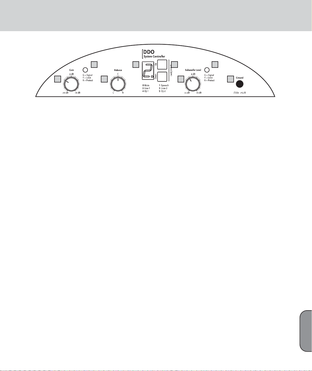
3 Connections and Control
Features
L.U.C.A.S IMPACT Subwoofer
1 Limiter LEDs
Much like rev counters, these LEDs indicate the
active system’s operating status. For more info, read
the sidebar “More about Limiter LEDs.”
2 Gain
Operation: Turn the Gain knob all the way down
(counterclockwise) before switching the system on.
Ensure the system is connected to the satellites and
all other connected components are on before
powering it up. Be sure to switch on the connected
mixer as well as all signal sources connected to it,
for example, keyboards, amps, effects, and so forth.
After you power the system up, set the Gain knob to
the 0 dBV or 12 o’clock setting. This is the preferred
level if you have connected a mixer. (Note: If you
connect a CD player or a keyboard directly to the
system, you may not be able to achieve peak volume
at this setting. If this is the case, twist the Gain knob
to the far right.)
If you hear distortion or a saturated signal, first
check the signal sources and, if possible, reduce the
output signal level there. If you are unable to turn
down the level of the signal sent to L.U.C.A.S
IMPACT at the signal source, adjust the input
sensitivity using the Gain knobs. (see also Tips and
Tricks—section 4).
3 Balance
Operation: Twist the Balance knob to the left or right
to adjust the relative balance of levels between the
left and right channels.
4 Display
Display: The numeric display indicates the currently
selected system configuration (0 to 5).
0 Mute - System switched to silent mode.
Zero sound signal reproduction.
1 Speech - Set-up for speech.
This mode places emphasis upon vocal and spoken
language reproduction. To minimize subsonic interference and background noise over the microphone,
the subwoofer level is reduced.
2 Live 1 - Set-up 1 for use during live performance.
The Live 1 setup enables punchy, dynamic bass with
rapid transient response. Vocals are likewise
predominant in this sound profile.
3 Live 2 - Set-up 2 for use during live performance.
The Live 2 set-up delivers softer and deeper bass
reproduction at a slightly lower level. The vocals are
slightly less in the foreground when compared to the
Live 1 set-up.
4 DJ 1 - Set-up 1 for reproduction of music from
CDs.
The DJ 1 set-up provides an ideal setting for CD
reproduction, with strong deep bass, discreet
midrange and accentuated highs.
5 DJ 2 - Set-up 2 for reproduction of CD/ MP3
music.
Like DJ1 above, the DJ 2 set-up can also be used for
CD reproduction, but is optimised for MP3-encoded
sources to revitalize the sound with more dynamic
bass, smoother highs and a more natural, less
compressed sound.
Note: A flashing display indicates that the controller
has muted the input. This mute function is triggered
via the input signal level. The system is muted when
its level falls below the threshold value. The system
is enabled as soon as the input signal level rises
above the threshold value.
5 Up/Down Buttons
Press these buttons to change system configurations. Operation: Simultaneously press and hold the
Up and Down buttons for about 1-2 seconds. Once
the letter U (Unlock) appears briefly in the display
you can use the Up and Down buttons to select the
desired setup. The buttons lock again automatically
after a moment, at which time the letter L (Lock)
appears briefly in the display.
6 Subwoofer Level
Handling: When this knob is set to the 12 o’clock
position, the subwoofer’s and the satellite’s
respective volumes are matched, ensuring the
proper balance between the subwoofer’s bass output
and the stallites’ mid/high-range output. If desired,
you can twist the Subwoofer Level knob to the left,
i.e. counterclockwise, to cut the subwoofer’s level by
as much as -12 dB and to the right to boost it by as
much as 6 dB.
7 Ground
Ground lift button for separating the signal and
chassis ground in the event of hum. To rid the
system of low-frequency hum, press the Ground
switch in. If this doesn’t solve the problem, check all
power and audio cables connected to L.U.C.A.S
IMPACT for damage, as well as all cables routing
signals to the mixing console (see also Tips and
Tr icks in Section 4).
L.U.C.A.S IMPACT -- user panel
2 3 6 7
1 4 5 1
English
Page 5
L.U.C.A.S IMPACT Manual 1.0
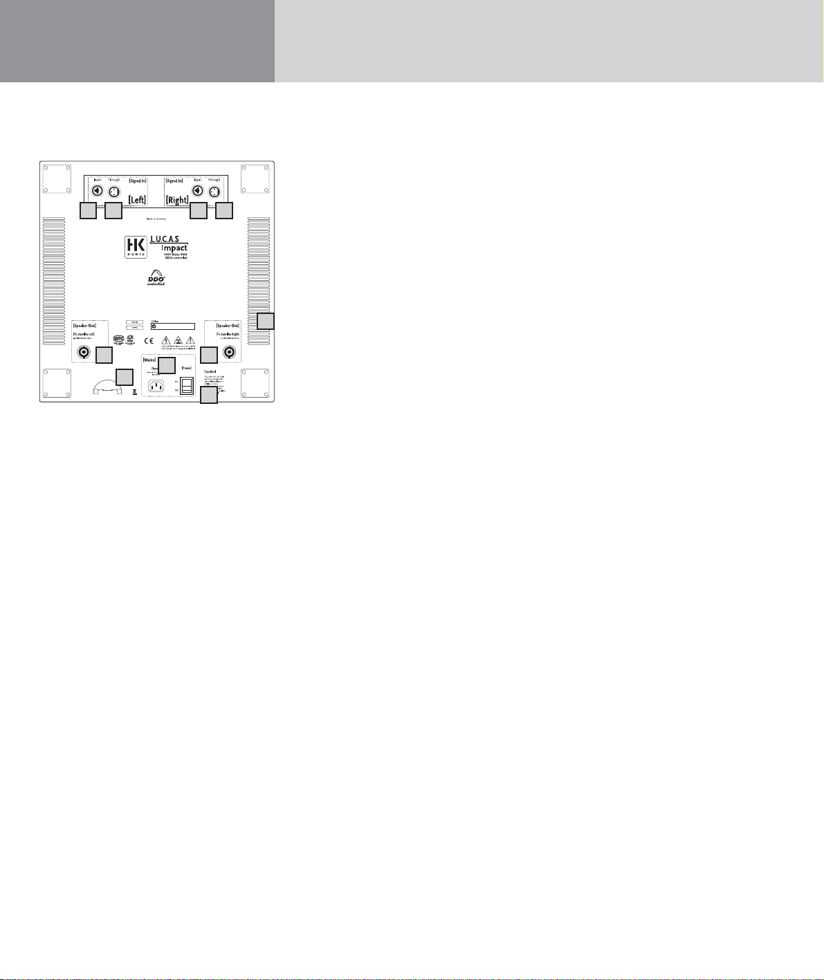
8 Input Left and Input Right (Combination XLR/1/4"
jacks)
L.U.C.A.S IMPACT is equipped with separate left and
right channel inputs for connecting to a mixer.
Connections: Connect the audio cables that route
the signal coming from your mixer (master
left/right, line out, or a similar circuit) to these
balanced inputs using microphone cables equipped
with XLR connectors. The XLR connectors’ pin
assignments must be as follows:
1= ground, 2= +, 3= -.
You can also use a 1/4" Tip-Ring-Sleeve plug to route
signals via balanced circuits. Unbalanced signals can
be patched in via a mono plug.
9 Through Left, Through Right
Connections: Parallel outputs for routing the line
signal (left or right) to other systems, outboard components, monitor power amps, etc., via XLR cables
10 Speaker Out (To Satellite Left und Right)
Connections: Connect these Speakon
®
outputs to
the left and right L.U.C.A.S IMPACT satellites using
speaker cables equipped with Speakon
®
connectors.
Note: Be sure to rotate the Speakon®connectors
clockwise until they lock in place!
11 Power Switch
Operation: On/off switch for the active system.
The display on the system controller glows orange to
indicate that the system is on.
Note: Once you have engaged the Power switch, it
will take several seconds for the display to light up
and the system to be ready for operation. This is
standard procedure and does not indicate a malfunction.
The active L.U.C.A.S IMPACT system should always
be switched on last after you power up all equipment connected to it, and should be switched off
first before you switch off all the other equipment
connected to it.
12 Mains Input
Connections: Use the factory-included mains cable
(power cord) to connect from this socket to a wall
receptacle. Caution! Make sure the local mains
voltage matches the voltage specified on the device.
Connecting the system to the wrong mains voltage
may destroy the L.U.C.A.S IMPACT system’s
electronic components.
13 Mains Cable Tab
Clamp the power cable into the tab to prevent it
from being pulled out inadvertently.
14 Fans
These fans (on the side and back of the housing)
keep the power amp modules cool. Always keep the
fan and ventilation vents free of dirt and debris, and
ensure they remain unobstructed so air can circulate
freely.
L.U.C.A.S IMPACT Satellite
Input
Connections: Connect the Speakon®inputs to the
left and right L.U.C.A.S IMPACT satellite outputs
using speaker cables equipped with Speakon“
connectors.
Note: Be sure to twist the Speakon®connectors
clockwise until they lock in place! You must first
disengage the safety catch before you can unplug
the connector. To do this, pull the bayonet catch
towards the cord.
8
12
13
14
11
10 10
9 8 9
L.U.C.A.S IMPACT - user panel rear
Page 6

9
4 Tips and Tricks
• Do not expose electronic circuitry to moisture!
When you set the system up outdoors, be sure to
protect it against rain. Keep soft drinks, beer or any
other liquids well away from the cabinets to protect
their electronic components from short circuits.
• To ensure proper ventilation, make sure the subwoofer is placed a sufficient distance away from
walls and isn’t covered by curtains and the like.
This is vital to keep the power amps cool.
• Ensure that the vents on the subwoofer’s side
panels are free of dirt and that the fan blades can
rotate freely. Otherwise, electronic components
may overheat and suffer damage.
• L.U.C.A.S IMPACT takes care of delivering
optimum sound—so provide it with optimum
input signals! Noise such as hum is generally
caused by defective cables, the wrong type of cables, or unbalanced signals being fed to the mixing
console. Check all audio cables and mains cables.
• Avoid distortion! Not only is it unpleasant to your
audience’s ears, it also endangers your equipment.
Make sure all components that are connected
directly and indirectly to L.U.C.A.S IMPACT have
sufficient power ratings, and that they are not
distorting from being driven at their respective
limits. Provide a clean, undistorted signal to the
system that won’t require backing off the Gain
knob to clean it up.
• Avoid ground loops! If, for example, you connect
the mixer to one mains circuit/wall outlet, and
L.U.C.A.S IMPACT to another, you may encounter a
ground loop. To prevent this problem, always
connect the L.U.C.A.S IMPACT system and the
mixing console to the same electrical circuit (same
phase!). If your equipment hums despite this precaution, the Ground Lift switch can be a great help.
CAUTION: Never tape over the plug’s ground
terminal – this endangers lives!
5 L.U.C.A.S IMPACT Accessories
HK AUDIO Speaker Add On Package
This is the complete L.U.C.A.S IMPACT accessory kit
consisting of two aluminum cabinet tripods, one gig
bag, and two speaker cables.
HK AUDIO Protective Covers for L.U.C.A.S IMPACT
This set comprises one cover for the subwoofer and
two covers for the satellites. Tear-resistant and
water-repellant, these rugged covers are thickly
padded to afford lasting protection for the L.U.C.A.S
IMPACT system during transport.
To learn more about Original HK Audio Accessories,
talk to your HK AUDIO dealer or visit
www.hkaudio.com.
English
Page 7
L.U.C.A.S IMPACT Manual 1.0
6 Troubleshooting
The display does not light up when switched on.
1 Check if the power cable is plugged into the Mains
Input.
2 Check if the mains power supply is providing
current.
The display lights up, but there is no sound coming
from the cabinets.
1 Check the cables connected to the Left and Right
inputs.
2 Check if the signal sources (mixer, keyboard, CD
player) are on.
3 Is the Gain knob turned up?
4 Check the speaker cables for damage.
5 Check if the Speakon“ connectors are fully engaged
in their sockets (rotated to the right). They must be
locked in place to establish an electrical
connection.
The subwoofer’s low frequency output is too soft.
1 Check the setting of the Subwoofer Level knob.
Adjust this knob to set the volume of the subwoofer to the desired level.
Sound seems distorted.
1 Check the LED displays on your mixer. They should
not be constantly in the red. If necessary, reduce
the volume at the mixer.
2 If the LED displays on your mixer are in the green,
turn back L.U.C.A.S IMPACT’s Gain knob.
3 Watch the LEDs of the Limit Left, Limit Right and
Limit Subwoofer displays on L.U.C.A.S IMPACT’s
control panel. These may light up yellow, but only
intermittently. Under no circumstances may they
continuously illuminate yellow. If this is the case,
turn the Gain down (knob counterclockwise).
Annoying hum
1 Check the cables connecting the source of the
audio signal to L.U.C.A.S IMPACT. Replace any
damaged cords.
2 If you cannot pinpoint the cause of the humming,
press the Ground switch in. This should remedy
the problem in most cases.
This is to certify that
HK AUDIO®L.U.C.A.S IMPACT
complies with the provisions of the Directive of
the Council of the European Communities on the
approximation of the laws of the Member States
relating to electromagnetic compatibility (EMC
Directive 89/336/EEC) and the low voltage Directive
(73/23/EEC). This declaration of conformity of the
European Communities is the result of an examination
carried out by the Quality Assurance Department
of STAMER GmbH in accordance with European
Standards EN 50081-1, EN 50082-1and EN 60065
for low voltage, as laid down in Article 10 of the
EMC Directive.
Stamer Musikanlagen
GmbH*
Magdeburger Str. 8
66606 St.Wendel
Lothar Stamer Dipl.Ing.
Managing Director
St.Wendel, 01/03/06
* Stamer Musikanlagen manufactures exclusively
for HK AUDIO
®
.
Page 8

Service Documents
TECHNICAL SERVICE:
Stamer Musikanlagen GmbH • Magdeburger Str. 8 • 66606 St.Wendel • Germany
Music & Sales P.E. GmbH • Leipziger Str. 3 • 66606 St.Wendel • Germany
L.U.C.A.S IMPACT Subwoofer
Line In: XLR female (pin 1= ground; 2= +, 3= -)
Input: Electronically balanced & floating
Input impedance: 47 k ohms
Sensitivity: +4 dBu
Max. input level: + 19 dBu
Parallel out: XLR male (pin 1= ground; 2=+, 3= -)
Speaker outputs: Speakon
®
NL 4 (pin 1+= +, 1-= -)
Digital controller:
Sampling frequency: 24 bits/ 48 kHz
Internal signal processing: 56 bits
Amplifiers:
Subwoofer output: 1x 500 W @ 8 ohms RMS /
Class D power amp
Satellites output: 2x 250 W @ 8 ohms RMS /
Class D power amp
Protective circuits: DDO™ controlled multi-band limiter
Speakers:
Woofer: 1x 15"
Subwoofer frequency response: 45 Hz -130 Hz, ± 3 dB
36 Hz -130 Hz, - 10 dB
SPL 1W / 1m: 101 dB (half space)
Max. SPL / 1m: 127 dB @ 10% THD (half space)
Weights and measures:
Weight: 32 kg / 70.4 lbs.
Dimensions without casters: 47.5 cm x 47 cm x 58.5 cm
(WxHxD) 18 3/4 " x 18 1/2" x 23"
L.U.C.A.S IMPACT Satellite
Inputs:
Speaker input: Speakon NL 4 (pin 1+= +, 1-= -)
Speakers:
Woofer: 1x 8“
Driver: 1x 1"
Directivity: 60°x 40° CD horn
Overall nominal impedance: 8 ohms
Nominal power handling: 250 W RMS
SPL 1W / 1m: 103 dB (half space)
Max. SPL / 1m: 125 dB @ 10% THD (half space)
Frequency response: 130 Hz - 19 kHz, +/- 3 dB
(via DDO™ Controller)
Crossover frequency (passive): 2.2 kHz/ 12 dB / octave
Driver protection: Dynamic protective circuit
Pole mount: HK Audio MonoTilt™ 36 mm, -10°
Weights and measures:
Weight: 7.5 kg / 16.5 lbs.
Dimensions (WxHxD): 25.8 cm x 38.5 cm x 28.5 cm
10 1/8" x 15 1/8" x 11 1/4"
General electrical data::
Protection class 1 (protectively earthed)
Max. current consumption: 4.4 A (220 – 240 V) • 8 A (110 – 120 V)
Max. power consumption: 1000 Watts
Mains voltage range: +/- 10%
Internal fuses: 250V/ T 8A IEC127
Ambient temperature range during operation: -10° C to +35° C
Technical Specifications L.U.C.A.S IMPACT
Page 9
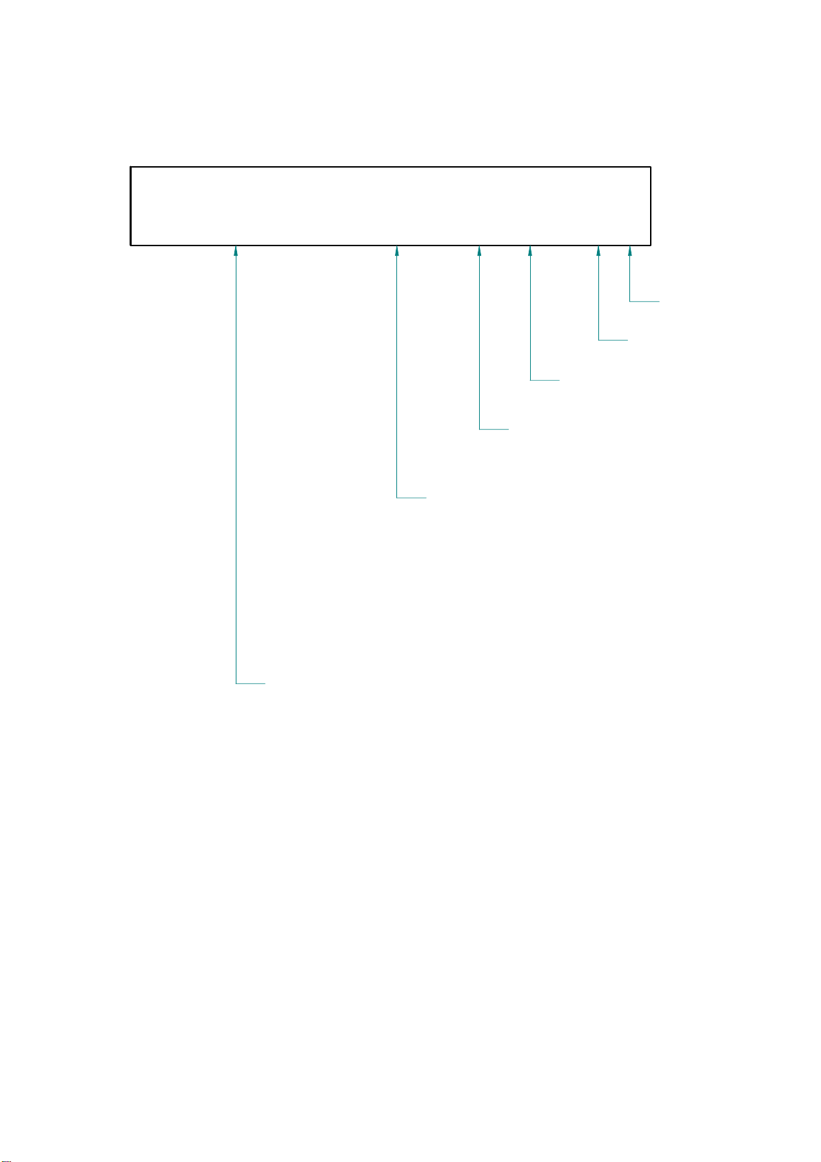
DRAWING-NUMBERS
EXAMPLE
HK0106-EX-R01-1A
VERSION
SERIAL NUMBER
DEPARTMENT:
R = R&D
REVISION
PROJECT-NR.:
HK = HK AUDIO
HU = HUGHES&KETTNER
MP = MINDPRINT
CHARACTER:
BL = SHEET METAL / BLECH
EX = EXPLODED DRAWING / EXPLOSIONSZEICHNUNG
HZ = CABINET / HOLZGEHÄUSE
KU = PLASTIC / KUNSTSTOFF
LP = PCB / LEITERPLATTEN
SO = MISCELLANEOUS / SONSTIGES
SP = SCHEMATIC / SCHALTPLÄNE
TR = TRANSFORMER / TRANSFORMATOR
GK = WIRING DIAGRAM / GERÄTEVERKABELUNG
Page 10
Stand
Standard for single wire confection.
16 B 150 638 I
-
I
IT
Z
W
Faston connector brass tin-plated DIN 46245
638
488
485
288
285
abiso
text
colour
B
R
BR
BL
W
YG
cross section
16
Q1.5
P + lfd Nr.
E + lfd Nr.
L + lfd Nr
FQL + lfd Nr.
17. Jun 04
Regarding special wirings like wiring harness or similar, drawings will be prepared and appropriate
the larger faston connector always mentioned at first. (Nathan drawing number controlling)
485 W Z I 1015
style 1015 according UL specifications
= completely insulated with black shrinktube or appropriate sleeve
= partly insulated; only crimp connection insulated.
no marking = without insulation
= with additional junction
no marking = without additional junction
= angled faston
no marking = straight faston
= 6,3 * 0,8 [mm]
= 4,8 * 0,8 [mm]
= 4,8 * 0,5 [mm] if fully insulated (I) insulation with blue shrinktube
if partly insulated (IT) use IF 602 485 .
= 2,8 * 0,8 [mm]
= 2,8 * 0,5 [mm] if fully insulated (I) insulation with blue shrinktube
if partly insulated (IT) use IF 602 485
= 5mm bared and tin-plated (teilabzug)
for special constructions, (for example. 4mm ringshaped faston)
lenght in mm within a 50 mm raster
= black (phase conductor)
= red
= brown
= blue (neutral conductor)
= white
= yellow-green (ground bonding/ earthing connection)
= AWG 16 (prefered usage)
= H07VK 1,5mm² (prefered usage)
wire designation:
= AWG single wire black, red, blue, brown or white
= AWG single wire green- yellow
. = twisted AWG double wire, lenght specification always in twisted condition
= crossover wiring H07VK
drawing numbers will be stored in the article archive.
Page 11

Confidential, for authorized service technicians only! Do not disclose
this information to or share these documents with third parties.
TECHNICAL SERVICE:
Stamer Musikanlagen GmbH • Magdeburger Str. 8 • 66606 St.Wendel • Germany
Music & Sales P.E. GmbH • Leipziger Str. 3 • 66606 St.Wendel • Germany
Service Documents
HK1005
L.U.C.A.S.
IMPACT
SUBWOOFER
Page 12

10E 974017
22E 976115
HK1005-EX-R03-1A
3E 502190
17
20
HK1005-HZ-R02-1C
23
15E 974355
2E 400275
15
HK1005-EX-R04-1A
21 E 976015
5E 962292
4E 962291
15
29E 994184
Q1.5 S 1000 638I-488I
Q1.5 R 1000 638I-488I
9E 974011
16E 974454
11E 974108
1E 1142
6E 970451
19
16
13
12
7E 972008
8E 972047
23 E 976159
18E 974475
INDEX
14E 974322
ÄNDERUNG
ZEICHNER
16
13 E 974233
12 E 974220
16
11
18
19 E 976001
20 E 976009
17 E 974455
TITEL:
HK1005-SUBWOOFER
66606 St. Wendel / Germany
ZEICHNUNGS-NR.:
ERSTELLT VON:
GEPRÜFT/
FREIGEGEBEN VON:
WERKSTOFF:
DATEINAME:
HK1005-EX-R05-1A
C. LORIS 1
HK1005-EX-R05-1A-GESAMT_BASS
EXPLOSION DRAWING COMPLETE
OBERFLÄCHE:
VERSION:
AM:
13.04.2006
AM:
n/a
REVISION:
BLATT:
2
BLÄTTER
A1
Page 13

INDEX
ÄNDERUNG
Pos. Artikel-Nr. 1 description Titel Menge
1 1142 front grille assembly Impact subwoofer Lucas Impact Frontgitterbaugruppe 1
2 400275 wooden cabinet Lucas Impact subwoofer Holzgeh. Lucas Impact Bass 1
3 502190 chassis Lucas Impact 100-240V Chassis Lucas Impact 100-240V 1
4 962291 stranded wire, color: red, 1000mm Litze FQL21 rot 1000mm 1
5 962292 stranded wire, color: black, 1000mm Litze FQL21 schwarz 1000mm 1
6 970451 front grill reeinforcement profile 15" Blech Verstrebungswinkel 15" 1
7 972008 damping wool Dämmwolle Hochbauschvlies 1
8 972047 PE-foam tube PE-Schaumstoff-Röhrchen 8
9 974011 hexagon socket head cap screw, M6x25, black Inbusschraube M6*25 sw 4
10 974017 hexagon socket countersunk head screw, M6x25, black Inbussenkschraube M6x25 sw 4
11 974108 plastic PCB spacer, 6.2x10x15, Polyamid black Dist.Hülse PE 6,2*10*15 [mm] 2
12 974220 hexagon socket countersunk head screw, M6x40, black Inbussenkschraube M6x40 sw 2
13 974233 washer, form A, D=6.4mm, zinc plated Unterleg-Scheibe 6,4 vz 2
14 974322 ABC-Spax-S screws for backwall, 4x20, black Rückwandschraube, 4*20 sw 2
15 974355 cross recessed panhead tapping screw with collar, 3.9x30, black Blechschr. KFR-Kopf 3,9* 30 sw 14
16 974454 plastic PCB spacer, 6.2x10x10, Polyamid black Dist.Hülse PE 6,2*10*10[mm] 4
17 974455 ABC-Spax-S chipboard screw, panhead Z, 5x16, black Pan Head-Z ABC-Spax sw 5*16 5
18 974475 hexagon socket head cap screw, M6x50, black Inbusschraube M6*50 sw 2
19 976001 rubber foot square, self-adhesive, black Gummifuss quadr. selbstkleb. sw 2
20 976009 rubber foot D38*H11 [mm] Gummifuss D38*H11 [mm] 5
21 976015 plug AD=1705 PA, black Lochstopfen AD=1705 PA-schwarz 1
22 976115 connector plate Befestigungsplatte M20 1
23 976159 plastic dish Premium One Griffinnenschale Premium One 2
24* 982037 sealing tape 2x6mm Iso-Zell-Band fadenvers. 2*6mm 0,22 lfdm
25* 982044 sealing tape 2x15mm Iso-Zell-Band fadenvers. 2*15mm 1,54 lfdm
26* 982078 sealing tape 2x20mm Iso-Zell-Band fadenvers. 2*20mm 0,50 lfdm
27* 986016 foam glue, Alfa D 4572 Klebstoff Alfa D 4572 xxx
28* 988165 1k polyurethane glue, 310mltrs. tube Polyurethan 1-K Kleber, 310ml Kartusche xxx
29 994184 B&C 15NW76-8OHMS 3" Coil B&C 15NW76-8OHMS 3" Coil 1
ZEICHNER
66606 St. Wendel / Germany
ZEICHNUNGS-NR.:
ERSTELLT VON:
GEPRÜFT/
FREIGEGEBEN VON:
WERKSTOFF:
DATEINAME:
HK1005-EX-R05-1A
C. LORIS 2
HK1005-EX-R05-1A-GESAMT_BASS
TITEL:
HK1005-SUBWOOFER
EXPLOSION DRAWING COMPLETE
OBERFLÄCHE:
VERSION:
AM:
13.04.2006
AM:
n/a
REVISION:
BLATT:
2
A1
BLÄTTER
Page 14

Pos. Artikel-Nr. 1 description Titel Menge
1 970335 front grille Streckgitter 1
2 972085 acoustic foam anthracite 15mm Akustikschaum Anthrazit 15mm 1
3 974158 snapon retaining ring (for logo) Schnellbefestiger f. Logo 1
4 980105 logo ´HK Audio´ 55x55 mm Logo ´HK Audio´ 55x55 mm 1
3 E 974158
INDEX
ÄNDERUNG
ZEICHNER
HK1005-SO-R06-1A
2E 972085
1 E 970335
HK1005-SO-R01-1A
service-nr.: E1142
4E 980105
66606 St. Wendel / Germany
ZEICHNUNGS-NR.:
ERSTELLT VON:
GEPRÜFT/
FREIGEGEBEN VON:
WERKSTOFF:
DATEINAME:
TITEL:
HK1005-IMPACT SUBWOOFER
EXPLOSION FRONT GRILLE
HK1005-EX-R03-1A
C. LORIS 1
HK1005-EX-R03-1A-FRONTGITTER_BASS
OBERFLÄCHE:
VERSION:
AM:
10.04.2006
AM:
n/a
REVISION:
BLATT:
1
BLÄTTER
A1
Page 15

1E 547056
15
23E 976007
13E 972041
INDEX
20E 974356
ÄNDERUNG
4 E 931304
5
2E 600088
HK1105-BL-R02-1C
10E 970767
22E 974521
26E 976169
14
21
22
17E 974228
21 E 974416
15
7
25 E 976141
15
7 E 952022
19 E 974290
9 E 959068
15 E 974110
3 E 600089
11 E 970769
HK1105-BL-R03-1A
16 E 974197
5 E 943239
HK1105-SO-R07-1A
12 E 970771
HK1005-BL-R02-1D
6 E 950060
ZEICHNER
18 E 974271
24 E 976125
14 E 974007
8 E 952260
66606 St. Wendel / Germany
ZEICHNUNGS-NR.:
ERSTELLT VON:
GEPRÜFT/
FREIGEGEBEN VON:
WERKSTOFF:
DATEINAME:
TITEL:
HK1005-IMPACT SUBWOOFER
EXPLOSION DRAWING CHASSIS
HK1005-EX-R04-1A
C. LORIS 1
HK1005-EX-R04-1A-CHASSIS
OBERFLÄCHE:
VERSION:
AM:
10.04.2006
AM:
n/a
REVISION:
BLATT:
5
BLÄTTER
A1
Page 16

Pos. Artikel-Nr. 1 description Titel Menge
1 547056 54 Lucas Impact Preamp Assembly 54 Lucas Impact Vorstufe 1
2 600088 60 Inputboard Lucas Max 60 Inputboard Lucas Max 1
3 600089 60 Mains Filter Lucas Impact 100-240V 60 Netzfilt.Lucas Imp 100-240V 1
4 931304 ferrite teroid core, 25x15x12 Ferritring, geschlossen 25x15x12 2
5 943239 dust protection, acoustic foam, black, PPI15, 5mm Staubschutz Lucas Max "07" 2
6 950060 hi-inrush, mains rocker switch, C13150VB Netzschalter gross C1350VB 1
7 952022 speakon chassis connector, NL4MP Speakonbuchse 4pol eckig 2
8 952260 power inlet, type 6100.3300, Schurter Netzbuchse Typ 6100.3300 1
9 959068 QuadAMP, 4ch PWM unit, RD0303 QuadAMP, 4ch PWM Modul, RD0303 1
10 970767 LUCAS MAX, preamp cover plate Blech Lucas MAX Vorstufemodul 1
11 970769 Lucas Max castor stabilizer Blech Lucas Max Stützwinkel 4
12 970771 Subwoofer Sheet Metal Chassis, Lucas Impact Blech Lucas Impact Bass Chassis 1
13 972041 rubber punching 25x25x15 Zellkaut.-Stanzteil 25x25x15 2
14 974007 hexagon socket oval head screw, M3x6, black Linsenschr.m.Innens. M3*6 sw 8
15 974110 self locking hexagon nut with plastic insert, M3, zinc plated Stopmutter M3 vz 11
16 974197 hexagon PCB spacer, type B, M3x8, zinc plated Dist. Bol Innen/Außengew. M3*8 vz 3
17 974228 cross recessed raised countersunk screw, M3x10, black Linsensenkschraube M3*10 sw 4
18 974271 cross recessed raised countersunk screw, M3x8, black Linsensenkschraube M3*8 sw 2
19 974290 self locking hexagon nut with plastic insert, M4, zinc plated Stopmutter M4 vz 4
20 974356 blind rivet steel standard, 6x10, black Blindniete Stahl schw. 6*10 16
21 974416 cross rec. raised counters. tap. screw w. cutting slot, 2.9x6.5, black Senkschr. f. Kunststoff 2,9*6,5, sw 4
22 974521 cross rec. raised counters. tap. screw w. cutting slot, 2.9x9.5, black Senkschr. f. Kunststoff 2,9*9,5, sw 4
23 976007 cable tie 2,5x100 (mm) Kabelbinder natur 2,5x100 (mm) 12
24 976125 mains cable strain relief, HKAudio custom made Kabelhalter HK Audio 1
25 976141 rubberbuffer 15x15 B Gummipuffer GM-Puffer 15x15 B 4
26 976169 Swivel castor LPA-TPA 75K-FK, black Lenkrolle 75mm RAL2005 schwarz 4
27* 986016 foam glue, Alfa D 4572 Klebstoff Alfa D 4572 xxx
INDEX
ÄNDERUNG
ZEICHNER
66606 St. Wendel / Germany
ZEICHNUNGS-NR.:
ERSTELLT VON:
GEPRÜFT/
FREIGEGEBEN VON:
WERKSTOFF:
DATEINAME:
HK1005-EX-R04-1A
C. LORIS 2
HK1005-EX-R04-1A-CHASSIS
TITEL:
HK1005-IMPACT SUBWOOFER
EXPLOSION DRAWING CHASSIS
OBERFLÄCHE:
VERSION:
AM:
10.04.2006
AM:
n/a
REVISION:
BLATT:
5
A1
BLÄTTER
Page 17

1
2
9
INDEX
ÄNDERUNG
7
ZEICHNER
7
TITEL:
3
8
66606 St. Wendel / Germany
ZEICHNUNGS-NR.:
ERSTELLT VON:
GEPRÜFT/
FREIGEGEBEN VON:
WERKSTOFF:
DATEINAME:
HK1005-EX-R04-1A
C. LORIS 3
HK1005-EX-R04-1A-CHASSIS
HK1005-IMPACT SUBWOOFER
EXPLOSION DRAWING CHASSIS
OBERFLÄCHE:
VERSION:
AM:
10.04.2006
AM:
n/a
REVISION:
BLATT:
5
A1
BLÄTTER
Page 18

E962030, Litze E5 grün-gelb 200mm,
AWG 16 Style 1015
16-YG-200-638-638 1015
E965617, Flachb. 20-2-150mm Typ 5,
AWG 28 flexibel grau RM1,27
E965607, Flachb. Flachb. 10-2-150mm Typ 5
AWG 28 flexibel grau RM1,27
E962261, Litze P23 schwarz 300mm,
16-B-300-488I-485IT 1015
E965617, Flachb. 20-2-150mm Typ 5,
AWG 28 flexibel grau RM1,27
E965626, Flachb. 20-2-200mm Typ 5,
AWG 28 flexibel grau RM1,27
All DIP switches are off
E962293, Litze P26 rot 350mm,
16 R 350 488I-485IT 1015
INDEX
ÄNDERUNG
ZEICHNER
E964050, Powerkabel Lucas Impact,
HK1005-KA-R01-1B
E962081, Litze TRI 1 schwarz 110mm,
16-B-110-638I-638I 1015
E962255, Litze P29 blau 120mm,
16-BL-120-638I-638I 1015
E962255, Litze P29 blau 120mm,
16 B 120 638I-638I 1015
E962081, Litze TRI 1 schwarz 110mm,
16-B-110-638I-638I 1015
E962261, Litze P23 schwarz 300mm,
16-B-300-488I-485IT 1015
E962038, Litze E4 grün-gelb 120mm,
16-YG-120-638-638 1015
E962293, Litze P26 rot 350mm,
16 R 350 488I-485IT 1015
66606 St. Wendel / Germany
ZEICHNUNGS-NR.:
ERSTELLT VON:
GEPRÜFT/
FREIGEGEBEN VON:
WERKSTOFF:
DATEINAME:
HK1005-EX-R04-1A
C. LORIS 4
HK1005-EX-R04-1A-CHASSIS
TITEL:
HK1005-IMPACT SUBWOOFER
EXPLOSION DRAWING CHASSIS
OBERFLÄCHE:
VERSION:
AM:
10.04.2006
AM:
n/a
REVISION:
BLATT:
5
A1
BLÄTTER
Page 19

Pos. Artikel-Nr. 1 Artikel-Nr. 2 Artikel-Nr. 3 description Titel Menge
1 962030 stranded wire 16- YG-200-638-368 1015 Litze 16-Y G- 200-638- 368 1015 1
2 962038 stranded wire 16-YG-120-638- 638 1015 Litze 16- YG- 120-638-638 1015 1
3 962081 stranded wi re 16-B-110-638I-638I 1015 Litze 16-B- 110-638I-638I 1015 2
4 962255 stranded wi re 16-BL-120-638I-638I 1015 Litze 16-BL-120- 638I-638I 1015 2
5 962261 stranded w ire 16- B-300- 488I-485IT 1015 Litze 16-B-300-488I- 485IT 1015 2
6 962293 stranded wire 16-R-350-488I-485IT 1015, A WG, UL, CSA Litze 16-R-350- 488I-485IT 1015, AWG, UL, CSA 2
7 964050 powercable Lucas Impact Powerkabel Lucas Impact 1
8 965607 f lat ri bbon cable 10- 2-150 typ 5 Fl achbandkabel 10-2- 150 typ 5 1
9 965617 flat ribbon cable 20- 2-150m m typ 5 Fl achbandkabel 20-2-150mm Typ 5 2
10 965626 flat ribbon cabl e 20-2- 200m m typ 5 Flachbandkabel 20-2- 200mm typ 5 1
INDEX
ÄNDERUNG
ZEICHNER
66606 St. Wendel / Germany
ZEICHNUNGS-NR.:
ERSTELLT VON:
GEPRÜFT/
FREIGEGEBEN VON:
WERKSTOFF:
DATEINAME:
HK1005-EX-R04-1A
C. LORIS 5
HK1005-EX-R04-1A-CHASSIS
TITEL:
HK1005-IMPACT SUBWOOFER
EXPLOSION DRAWING CHASSIS
OBERFLÄCHE:
VERSION:
AM:
10.04.2006
AM:
n/a
REVISION:
BLATT:
5
A1
BLÄTTER
Page 20

Pos. Artikel-Nr. 1 description Titel Menge
1 547056 54 Lucas Impact Preamp (Display PCB) 54 Lucas Impact Vorstufe (Displayplatine) 1
5E 966076
2 547056 54 Lucas Impact Preamp (PCB only) 54 Lucas Impact Vorstufe (Platine) 1
3 966046 plunger type key top, 9*9, B32-1210 Knopf-Taster 9*9 B32-1210 2
4 966075 Push-Bottom-Trio Knopf-Swtich TRIO 1
5 966076 softtouch poti knob, REAN, flexifit, F313 Knopf-Poti 13mm sw/sw/ws 3
6 970766 Lucas MAX/Impact, control panel, acryl glass Plexiglas Lucas Max 1
7 974110 self locking hexagon nut with plastic insert, M3, zinc plated Stopmutter M3 vz 5
8 974221 hexagon socket countersunk head screw, M3x8, zinc plated Inbussenkschraube M3x8 vz 5
9 974362 hexagon PCB spacer, type B, M3x12, zinc plated Dist. Bol Innen/Außengew. M3*12 vz 5
HK1105-KU-R01-1C
6E 970766
8 E 974221
3 E 966046
1 E 547056
9 E 974362
4 E 966075
2 E 547056
TITEL:
INDEX
ÄNDERUNG
ZEICHNER
7 E 974110
66606 St. Wendel / Germany
ZEICHNUNGS-NR.:
ERSTELLT VON:
GEPRÜFT/
FREIGEGEBEN VON:
WERKSTOFF:
DATEINAME:
HK1005-EX-R07-1A
C. LORIS 1
HK1005-EX-R07-1A-PREAMP
HK1005-SUB PREAMP ASSEMBLY
EXPLOSION DRAWING
OBERFLÄCHE:
VERSION:
AM:
03.05.2006
AM:
n/a
REVISION:
BLATT:
1
BLÄTTER
A1
Page 21

Spare Parts Lis t fo r: HK1005-SP-R01-1C
Project: LUCAS IMPACT
Project Number: HK1005
Assembly: Preamp
Pos. Article No. Description Bezeichnung Reference Designators Quantity
1 836004
2 914091
3 950021
4 950083
1
Surf ace mount LED display 7-Segmentdispl. Orange SMD14mm LD100 1
Poti B10K lin mono CC heavy T Poti B10K lin mono CC heavy T P3, P2, P1 3
tactile push button w ith projected plunger Taster Tac- Sw itch B3F-4055 SW100, SW101 2
Push Button Switch, ver tical, (2 Pols) Drucksc halter ohne LED 11,25mm SW1 1
3
INDEX
ÄNDERUNG
2 2 2
ZEICHNER
66606 St. Wendel / Germany
ZEICHNUNGS-NR.:
ERSTELLT VON:
GEPRÜFT/
FREIGEGEBEN VON:
WERKSTOFF:
DATEINAME:
HK1005-SP-R01-1A
MICHAEL BOHLENDER 1
MICHAEL BOHLENDER 29.06.2006
HK1005-SP-R01-1C-Preamp
4
TITEL:
HK1005 -- L.U.C.A.S. IMPACT
PREAMP PCB SPARE PARTS
OBERFLÄCHE:
VERSION:
AM:
29.06.2006
AM:
n/a
REVISION:
BLATT:
1
A1
BLÄTTER
Page 22

E 959068
QuadAMP, 4ch PWM unit
To ensure the procedure of our quality assurance
(burn-in-test, quality-test,...) please send the complete
module to our technical service for replacement.
For customer inquiry please contact our service-team.
Page 23

HK1005-EX-R05-1A-SUB-COMPLETE
G
Article No. 1 (230V) Article No. 2 (117V) Article No. 3 (100V) Description Bezeichnung Quantity
E1142 front grille assembly Impact subwoofer Lucas Impact Frontgitterbaugruppe 1
400275 wooden cabinet Lucas Impact subwoofer Holzgeh. Lucas Impact Bass 1
502190 chassis Lucas Impact 100-240V Chassis Lucas Impact 100-240V 1
962291 stranded wire, color: red, 1000mm Litze FQL21 rot 1000mm 1
962292 stranded wire, color: black, 1000mm Litze FQL21 schwarz 1000mm 1
970451 front grill reeinforcement profile 15" Blech Verstrebungswinkel 15" 1
972008 damping wool Dämmwolle Hochbauschvlies 1
972047 PE-foam tube PE-Schaumstoff-Röhrchen 8
974011 hexagon socket head cap screw, M6x25, black Inbusschraube M6*25 sw 4
974017 hexagon socket countersunk head screw, M6x25, black Inbussenkschraube M6x25 sw 4
974108 plastic PCB spacer, 6.2x10x15, Polyamid black Dist.Hülse PE 6,2*10*15 [mm] 2
974220 hexagon socket countersunk head screw, M6x40, black Inbussenkschraube M6x40 sw 2
974233 washer, form A, D=6.4mm, zinc plated Unterleg-Scheibe 6,4 vz 2
974322 ABC-Spax-S screws for backwall, 4x20, black Rückwandschraube, 4*20 sw 2
974355 cross recessed panhead tapping screw with collar, 3.9x30, black Blechschr. KFR-Kopf 3,9* 30 sw 14
974454 plastic PCB spacer, 6.2x10x10, Polyamid black Dist.Hülse PE 6,2*10*10[mm] 4
974455 ABC-Spax-S chipboard screw, panhead Z, 5x16, black Pan Head-Z ABC-Spax sw 5*16 5
974475 hexagon socket head cap screw, M6x50, black Inbusschraube M6*50 sw 2
976001 rubber foot square, self-adhesive, black Gummifuss quadr. selbstkleb. sw 2
976009 rubber foot D38*H11 [mm] Gummifuss D38*H11 [mm] 5
976015 plug AD=1705 PA, black Lochstopfen AD=1705 PA-schwarz 1
976115 connector plate Befestigungsplatte M20 1
976159 plastic dish Premium One Griffinnenschale Premium One 2
982037 sealing tape 2x6mm Iso-Zell-Band fadenvers. 2*6mm 0,22 lfdm
982044 sealing tape 2x15mm Iso-Zell-Band fadenvers. 2*15mm 1,54 lfdm
982078 sealing tape 2x20mm Iso-Zell-Band fadenvers. 2*20mm 0,50 lfdm
986016 foam glue, Alfa D 4572 Klebstoff Alfa D 4572 xxx
988165 1k polyurethane glue, 310mltrs. tube Polyurethan 1-K Kleber, 310ml Kartusche xxx
994184 B&C 15NW76-8OHMS 3" Coil B&C 15NW76-8OHMS 3" Coil 1
HK1005-EX-R03-1A-SUB-FRONT GRILLE
Article No. 1 (230V) Article No. 2 (117V) Article No. 3 (100V) Description Bezeichnung Quantity
970335 front grille Streckgitter 1
972085 acoustic foam anthracite 15mm Akustikschaum Anthrazit 15mm 1
974158 snapon retaining ring (for logo) Schnellbefestiger f. Logo 1
980105 logo ´HK Audio´ 55x55 mm Logo ´HK Audio´ 55x55 mm 1
HK1005-EX-R04-1A-CHASSIS / CABLIN
Article No. 1 (230V) Article No. 2 (117V) Article No. 3 (100V) Description Bezeichnung Quantity
547056 54 Lucas Impact Preamp Assembly 54 Lucas Impact Vorstufe 1
600088 60 Inputboard Lucas Max 60 Inputboard Lucas Max 1
600089 60 Mains Filter Lucas Impact 100-240V 60 Netzfilt.Lucas Imp 100-240V 1
931304 ferrite teroid core, 25x15x12 Ferritring, geschlossen 25x15x12 2
943239 dust protection, acoustic foam, black, PPI15, 5mm Staubschutz Lucas Max "07" 2
950060 hi-inrush, mains rocker switch, C13150VB Netzschalter gross C1350VB 1
952022 speakon chassis connector, NL4MP Speakonbuchse 4pol eckig 2
952260 power inlet, type 6100.3300, Schurter Netzbuchse Typ 6100.3300 1
959068 QuadAMP, 4ch PWM unit, RD0303 QuadAMP, 4ch PWM Modul, RD0303 1
962030 stranded wire 16-YG-200-638-368 1015 Litze 16-YG-200-638-368 1015 1
Page 24

962038 stranded wire 16-YG-120-638-638 1015 Litze 16-YG-120-638-638 1015 1
Y
962081 stranded wire 16-B-110-638I-638I 1015 Litze 16-B-110-638I-638I 1015 2
962255 stranded wire 16-BL-120-638I-638I 1015 Litze 16-BL-120-638I-638I 1015 2
962261 stranded wire 16-B-300-488I-485IT 1015 Litze 16-B-300-488I-485IT 1015 2
962293 stranded wire 16-R-350-488I-485IT 1015, AWG, UL, CSA Litze 16-R-350-488I-485IT 1015, AWG, UL, CSA 2
964050 powercable Lucas Impact Powerkabel Lucas Impact 1
965607 flat ribbon cable 10-2-150 typ 5 Flachbandkabel 10-2-150 typ 5 1
965617 flat ribbon cable 20-2-150mm typ 5 Flachbandkabel 20-2-150mm Typ 5 2
965626 flat ribbon cable 20-2-200mm typ 5 Flachbandkabel 20-2-200mm typ 5 1
970767 LUCAS MAX, preamp cover plate Blech Lucas MAX Vorstufemodul 1
970769 Lucas Max castor stabilizer Blech Lucas Max Stützwinkel 4
970771 Subwoofer Sheet Metal Chassis, Lucas Impact Blech Lucas Impact Bass Chassis 1
972041 rubber punching 25x25x15 Zellkaut.-Stanzteil 25x25x15 2
974007 hexagon socket oval head screw, M3x6, black Linsenschr.m.Innens. M3*6 sw 8
974110 self locking hexagon nut with plastic insert, M3, zinc plated Stopmutter M3 vz 11
974197 hexagon PCB spacer, type B, M3x8, zinc plated Dist. Bol Innen/Außengew. M3*8 vz 3
974228 cross recessed raised countersunk screw, M3x10, black Linsensenkschraube M3*10 sw 4
974271 cross recessed raised countersunk screw, M3x8, black Linsensenkschraube M3*8 sw 2
974290 self locking hexagon nut with plastic insert, M4, zinc plated Stopmutter M4 vz 4
974356 blind rivet steel standard, 6x10, black Blindniete Stahl schw. 6*10 16
974416 cross rec. raised counters. tap. screw w. cutting slot, 2.9x6.5, black Senkschr. f. Kunststoff 2,9*6,5, sw 4
974521 cross rec. raised counters. tap. screw w. cutting slot, 2.9x9.5, black Senkschr. f. Kunststoff 2,9*9,5, sw 4
976007 cable tie 2,5x100 (mm) Kabelbinder natur 2,5x100 (mm) 12
976125 mains cable strain relief, HKAudio custom made Kabelhalter HK Audio 1
976141 rubberbuffer 15x15 B Gummipuffer GM-Puffer 15x15 B 4
976169 Swivel castor LPA-TPA 75K-FK, black Lenkrolle 75mm RAL2005 schwarz 4
986016 foam glue, Alfa D 4572 Klebstoff Alfa D 4572 xxx
HK1005-EX-R07-1A-PREAMP-ASSEMBL
Article No. 1 (230V) Article No. 2 (117V) Article No. 3 (100V) Description Bezeichnung Quantity
547056 54 Lucas Impact Preamp (Display PCB) 54 Lucas Impact Vorstufe (Displayplatine) 1
547056 54 Lucas Impact Preamp (PCB only) 54 Lucas Impact Vorstufe (Platine) 1
966046 plunger type key top, 9*9, B32-1210 Knopf-Taster 9*9 B32-1210 2
966075 Push-Bottom-Trio Knopf-Swtich TRIO 1
966076 softtouch poti knob, REAN, flexifit, F313 Knopf-Poti 13mm sw/sw/ws 3
970766 Lucas MAX/Impact, control panel, acryl glass Plexiglas Lucas Max 1
974110 self locking hexagon nut with plastic insert, M3, zinc plated Stopmutter M3 vz 5
974221 hexagon socket countersunk head screw, M3x8, zinc plated Inbussenkschraube M3x8 vz 5
974362 hexagon PCB spacer, type B, M3x12, zinc plated Dist. Bol Innen/Außengew. M3*12 vz 5
HK1005-SP-R01-1C-Preamp
Article No. 1 Ref. Designator Description Bezeichnung Quantity
836004 LD100 Surface mount LED display 7-Segmentdispl. Orange SMD14mm 1
914091 P3, P2, P1 Poti B10K lin mono CC heavy T Poti B10K lin mono CC heavy T 3
950021 SW100, SW101 tactile push button with projected plunger Taster Tac-Switch B3F-4055 2
950083 SW1 Push Button Switch, vertical, (2 Pols) Druckschalter ohne LED 11,25mm 1
Page 25

87654321
EMI/HF damping
D
D
+5V
R116
U100
3
+5V
DGND
R100
+5V
DETECT
10K*
ISP_MOSI ISP_SCK
DETECT
C
+5V
RESET
1
DGND
MAX803L
ISP & Service Connector
2
+5V
4
6
DGND
8
10
+5V
DGND
Pin Length = 12.6mm / 6.8mm
JP101
SL-16P08X2
2
1
3
5
7
9
1112
1314
1516
RESET
ISP_MISO
DSP_SS
PD1-TXDPD0-RXD
CTRL_SDA
CTRL_SCLWP_EEPROM
RESET
1K0*
TP1
TP-SMD10
MicroController & Peripherals
CTRL_BUS
RESET
03-uC-Peripherals.sch
02-SigmaDSP-Codec
02-SigmaDSP-Codec.sch
CTRL_BUS
04-AnalogIO
04-AnalogIO.sch
DAOUT1-
DAOUT1+
DAOUT1+
DAOUT1-
DAOUT2+
DAOUT2-
DAOUT2+
DAOUT2-
DAOUT3+
DAOUT3-
DAOUT3+
DAOUT3-
UC_CLK
UC_CLK
UC_CLK
ADINL+
ADINL+
ADINL-
ADINL-
ADINR+
ADINR+
ADINR-
ADINR-
HO100
DK-R70-B32
NA
HO102
DK-R70-B32
NA
HO103
DK-R70-B32
NA
HO1
DK-R70-B32
NA
HO2
DK-R70-B32
NA
HO3
DK-R70-B32
NA
HO4
DK-R70-B32
NA
C119
1n0-K*
C120
1n0-K*
C121
1n0-K*
C14
47p-K*
C21
47p-K*
C22
47p-K*
C31
47p-K*
-15V
+15V
+5V
DGND
C
DGND
DGND
DGND
board protection
CTRL_BUS
ADINL+
ADINL-
ADINR+
DAOUT1-
DAOUT2-
DAOUT3-
DAOUT1+
DAOUT2+
DAOUT3+
B
AOUT
ADINR-
+5V
+15V
05-Amp_Matrix
05-Amp_Matrix.Sch
AOUT
-15V
CTRL_BUS
C108
22uF/16V-TD
D100
P6SMB6,8A
C110
22uF/16V-TD
D102
P6SMB18A
C109
22uF/16V-TD
D103
P6SMB18A
DGND
DGND
B
NA = not assembled part ----- EX = exclusive part, no alternative allowed
HT = high temperature part, assemble with distance from PCB
HO7
A
NDK-R0-B40
HO5
NDK-R0-B40
HO8
NDK-R0-B40
HO6
NDK-R0-B40
66606 St. Wendel / Germany
Number: Version: Revision:1HK1005-SP-R01 D
F. Sitter
Drawn by: Date:
A. Peter
Checked by:
PCB No.:
All rights reserved. No part of this schematic may be reproduced, stored in a retrieval system, transmitted in any form or by any means, electronic, mechanical, photocopying, recording or otherwise, without the prior permission of the author. Filename: HK1005-SP-R01-1D.sch
1 2 3 4 5 6 7 8
Title:
HK1005
A
Date:
07.10.2005
12.05.2005
Page:
5
1
Pages
Page 26

87654321
Serial I/F (Debug only)
JP301
PD0-RXD
1
2
PD1-TXD
3
PS_UP
PS_DO
DGND
+5V
C303
100n-K*
DGND DGND
RESET
CTRL_SCL
CTRL_SDA
DGNDA0
DGND
DGND
DGND
PS_UP
PS_DO
4
+5V
SL-04P04X1
NA
C304
100n-K*
15
1
2
3
4
5
DGND
+5V
L300
100uH/CM45
C307
4,7uF/6V-TA
DGND
+5V
DGND
U302
RESET
SCL
SDA
A0
A1
A2
GND8VDD
PCA9557PW
JP101-1
8
7
6
5
4
3
2
1
SL-08P08X1-SW
C306
100n-K*
I/O0
I/O1
I/O2
I/O3
I/O4
I/O5
I/O6
I/O7
D
C
R30 330R*
R28 330R*
R26 330R*
6
7
9
10
11
12
13
14
16
+5V
R23 330R*
R21 330R*
R20 330R*
R17 330R*
R15 330R*
8
7
6
5
4
3
2
1
JP100-1
SL-08P08X1-SW
B
R304
LD300
DGND
D
330R*
+5V
R98
R97
10K*
DGND
DGND
DGND
37
36
35
34
33
32
31
30
27
29
28
26
25
24
23
22
21
20
19
6
18
39
SPI_MISO
10K*
DGND
DGND
DGND
DGND
C300
100n-K*
DGND DGND DGND
RESET
CTRL_BUS
C
LEFT
RV110F-40E1-125A-B10K-0C61
RIGHT
RV110F-40E1-125A-B10K-0C61
B
SUB
RV110F-40E1-125A-B10K-0C61
+5V
L R
DGND
+5V
L R
DGND
+5V
L R
DGND
UC_CLK
P1
R19
GPIO0
100R*
100n-K*
DGND
P2
R22
GPIO1
100R*
100n-K*
DGND
P3
R24
GPIO2
100R*
100n-K*
DGND
RESET
LIMIT_1
LIMIT_2
LIMIT_3
PB3-DLD1G
DSP_SS
ISP_MOSI
ISP_MISO
ISP_SCK
UC_CLK
PD0-RXD
PD1-TXD
PD2-INT0
PD3-DLD1R
PD6-DLD3G
PD7-DLD3R
PD4-DLD2G
PD5-DLD2R
C7
WP_EEPROM
C8
C9
PD3-DLD1R
PB3-DLD1G
R27
R29
330R*
330R*
100n-K*
100n-K*
PD4-DLD2G
R31
330R*
+5V
C305
100n-K*
DGND
PD5-DLD2R
R32
330R*
U300
5
VCC
17
VCC
38
VCC
4
RESET
40
PB0 (XCK/T0)
41
PB1 (T1)
42
PB2 (AIN0/INT2)
43
PB3 (AIN1/OC0)
44
PB4 (SS)
1
PB5 (MOSI)
2
PB6 (MISO)
3
PB7 (SCK)
7
XTAL2
8
XTAL1
9
PD0 (RxD)
10
PD1 (TxD)
11
PD2 (INT0)
12
PD3 (INT1)
13
PD4 (OC1B)
14
PD5 (OC1A)
15
PD6 (ICP)
16
PD7 (OC2)
ATMEGA32-16AI
Application Memory
8
+5V
7
4
DGND
PD6-DLD3G
PD7-DLD3R
R33
R34
330R*
330R*
U301
VCC
WP
VSS
M24256-B
(ADC0) PA0
(ADC1) PA1
(ADC2) PA2
(ADC3) PA3
(ADC4) PA4
(ADC5) PA5
(ADC6) PA6
(ADC7) PA7
(TOSC2) PC7
(TSOC1) PC6
A1
A2
SDA
SCL
ISP_MISO
AVCC
AGND
(TDI) PC5
(TDO) PC4
(TMS) PC3
(TCK) PC2
(SDA) PC1
(SCL) PC0
AREF
GND
GND
GND
1
2
3
5
6
R309
100R*
C302
C301
KP-3216EC-RED
+5V +5VDGND DGND
R99
10K*
R306
4K7*
R305
4K7*
+5V
+5V
R101
10K*
R25
4K7*
+5V
R1
10K*
R2
10K*
STATUS_LED
GPIO0
GPIO2
GPIO1
RESET_DSP
WP_EEPROM
RESET_CODEC
DETECT
STATUS_LED
AVCC
PS_OT
AMP_OT
MUTE_IN
MUTE_ALL
PS_UP
PS_DO
CTRL_SDA
CTRL_SCL
+5V
+5V
LED-5MM-DUO
DGND
LD5
LED-5MM-DUO
DGND
LD6
LD7
LED-5MM-DUO
DGND
LEFT RIGHT SUB
A
R311
ISP_MOSI
100R*
R313
ISP_SCK
100R*
SPI decoupling
SPI_MOSI
SPI_SCK
NA = not assembled part ----- EX = exclusive part, no alternative allowed
HT = high temperature part, assemble with distance from PCB
66606 St. Wendel / Germany
Number: Version: Revision:1HK1005-SP-R01 D
F. Sitter
Drawn by: Date:
A. Peter
Checked by:
PCB No.:
All rights reserved. No part of this schematic may be reproduced, stored in a retrieval system, transmitted in any form or by any means, electronic, mechanical, photocopying, recording or otherwise, without the prior permission of the author. Filename: 03-uC-Peripherals.sch
1 2 3 4 5 6 7 8
Title:
HK1005_Preamp
Date:
07.10.2005
12.05.2005
Page:
5
A
3
Pages
Page 27

JP5
NA
JST-B03B-EH-A
R35
D1
NA
PMLL4148
10
-
R
G
B
3
PMLL4148
-
REL2A
FRT5-1
NA
3
2
1
240R*
NA
D
+15V
REL1A
FRT5-1
NA
1
+
JP3
JST-B03B-EH-A
NA
CTRL_BUS
+15V
B1G2R
C
PD0-RXD
PD1-TXD
JP10
SEK18-20P
+5V
1 2
3 4
5 6
7 8
9 10
11 12
13 14
DGND
+5VA
-15V
B
JP4
3
R
2
G
1
B
JST-B03B-EH-A
NA
R36
D2
240R*
NA
NA
1
10
+15V
+
FB1
1400/70
FB5
1400/70
C13
47p-K*
C37
22,0uF/25V-S6
R37
470K*
R38
470K*
C38
22,0uF/25V-S6
C20
47p-K*
C12
47p-K*
C16
47p-K*
FB4
1400/70
3
LTV75-SD11.25-CS
4
LTV75-SD11.25-CS
15 16
17 18
19 20
C17
47p-K*
R52
47R/1W
C19
SW1A
SW1B
C18
47p-K*
21
56
47n/250V
R76
2K0*
R77
2K0*
+5VA
V-
R84
2K7*
R83
3K3*
V+
D7
PMLL4148
D8
PMLL4148
D9
PMLL4148
D10
PMLL4148
V+
C61
R87
20K*
R88
20K*
R81
C60
10K*
100n-K*
R82
10K*
100uF/6V-TD
C25
R85
2K0*
R86
2K0*
V+
D11
PMLL4148
R89
20K*
D12
PMLL4148
V-
D13
PMLL4148
R90
20K*
D14
PMLL4148
FB7
1400/70
47p-K*
C26
47p-K*
C27
47p-K*
FB8
1400/70
FB9
1400/70
C28
47p-K*
C29
47p-K*
C39
22,0uF/25V-S6
R39
470K*
R40
470K*
C40
22,0uF/25V-S6
C30
47p-K*
V+
R3
10K* NA
R51
7K5*
C41
56p-K*
V-
U2A
2
-
3
+
VCCVEE
4 11
V+
U2B
5
+
6
-
MC33079
1
MC33079
7
R54
91R*
R55
91R*
C54
56p-K*
R6
7K5*
R7
10K*NA
R8
10K*NA
R53
7K5*
C44
56p-K*
U2D
13
-
12
+
MC33079
U2C
10
+
9
-
MC33079
R56
14
91R*
R57
8
91R*
C57
56p-K*
R12
7K5*
R13
10K*NA
V-V+
A
BR1
BR2
BR3
0*
0*
NA
BR4
0*
0*
NA
C10
100n-K*
-15V+15V +5VA
All rights reserved. No part of this schematic may be reproduced, stored in a retrieval system, transmitted in any form or by any means, electronic, mechanical, photocopying, recording or otherwise, without the prior permission of the author. Filename: 04-AnalogIO.sch
1 2 3 4 5 6 7 8
ADINL-
ADINL+
ADINR-
ADINR+
V-V+
2
3
4
C62
2n7-K*
7
8
9
2
3
4
C63
2n7-K*
7
8
9
C11
100n-K*
REL1B
FRT5-1
NA
REL1C
FRT5-1
NA
REL2B
FRT5-1
NA
REL2C
FRT5-1
NA
ADINL-
ADINL+
ADINR-
ADINR+
C64
100n-K*
DAOUT1+
DAOUT1-
DAOUT2+
DAOUT2-
DAOUT3+
DAOUT3-
-15V+15V
C65
100n-K*
TP2
TP-SMD10
DAOUT1+
DAOUT1-
TP3
TP-SMD10
TP4
TP-SMD10
DAOUT2+
DAOUT2-
TP5
TP-SMD10
TP6
TP-SMD10
DAOUT3+DAOUT3-
TP7
TP-SMD10
C66
100n-K*
R58
220R*
C42
68p-K*
R59
220R*
R60
220R*
C43
68p-K*
R61
220R*
R62
220R*
C45
68p-K*
R63
220R*
R64
8K2*
C46
22,0uF/16V-S4
C1
1n0-K*
R42
22K*
R4
10K*
2
3
R65
C47
22,0uF/16V-S4
C2
1n0-K*
R44
22K*
R5
10K*
8K2*
6
5
U3B
MC33078
R66
8K2*
C48
22,0uF/16V-S4
C3
1n0-K*
R45
22K*
R9
10K*
2
3
R67
C49
22,0uF/16V-S4
C4
1n0-K*
R48
22K*
R10
10K*
8K2*
6
5
U8B
MC33078
R68
C50
22,0uF/16V-S4
C5
1n0-K*
R49
22K*
R11
10K*
8K2*
6
5
U4B
MC33078
R69
8K2*
C51
22,0uF/16V-S4
C6
1n0-K*
-15V+15V
C67
100n-K*
C68
100n-K*
R14
10K*
R50
22K*
-15V+15V
C69
100n-K*
2
3
NA = not assembled part ----- EX = exclusive part, no alternative allowed
HT = high temperature part, assemble with distance from PCB
66606 St. Wendel / Germany
Number: Version: Revision:1HK1005-SP-R01 D
F. Sitter
Drawn by: Date:
A. Peter
Checked by:
PCB No.:
C52
56p-K*
-15V
-
+
+15V
C53
56p-K*
-
+
C55
56p-K*
-15V
-
+
+15V
C56
56p-K*
-
+
C58
56p-K*
-
+
C59
56p-K*
-15V
-
+
+15V
87654321
U3A
R70
47R*
R71
47R*
AOUT1-
AOUT1+
D
1
VCCVEE
8 4
MC33078
7
U8A
R72
47R*
R73
47R*
R74
47R*
R75
47R*
AOUT2-
AOUT2+
AOUT3-
AOUT3+
C
B
AOUT
1
VCCVEE
8 4
MC33078
7
7
U4A
1
VCCVEE
8 4
MC33078
Title:
HK1005_Preamp
A
Date:
07.10.2005
12.05.2005
Page:
5
4
Pages
Page 28

87654321
C234
C239
C227
C241
100n-K*
10uF/10V-TA
U202
VD
VD
DGND
DGND
VLC
RESET
INT
SCL/CCLK
SDA/CDOUT
AD1/CDIN
AD0/CS
VLS
ADC_IN2
ADC_IN1
ADC_SCLK
ADC_LRCK
ADC_SDOUT
DAC_SCLK
DAC_LRCK
DAC_SDIN1
DAC_SDIN2
DAC_SDIN3
DAC_SDIN4
OMCK
RMCK
GPO7
GPO6
GPO5
GPO4
GPO3
GPO2
GPO1
CS42426-CQZ
10uF/10V-TA
NA = not assembled part ----- EX = exclusive part, no alternative allowed
HT = high temperature part, assemble with distance from PCB
Number: Version: Revision:1HK1005-SP-R01 D
Drawn by: Date:
Checked by:
PCB No.:
L200
C223
100n-K*
TP200
TP-SMD10
+5V
DGND
DGND DGND+5V
R215
10K*
FB201
200/800
FB202
200/800
R212
10K*
C242
10n-K*
R211
10K*
C203
1n0-K*
C204
1n0-K*
C210
10n-K*
PD2-INT0
C226
C243
100n-K*
100n-K*
+5V
C224
C208
100n-K*
10n-K*
DGND DGND DGND
+5V
C225
C209
100n-K*
10n-K*
DGND DGND DGND
R201
100R*
R205
SAI_BCLK
47R*
R206
SAI_LRCLK
47R*
R207
SAI_ADIN
47R*
R208
SAI_OUT12
47R*
R209
SAI_OUT34
47R*
C205
1n0-K*
C231
1,0uF/16V-TA
C232
1,0uF/16V-TA
C244
10uF/10V-TA
DGND
DGND
10uF/10V-TA
RESET_CODEC
CTRL_SCL
CTRL_SDA
R216
10K*
R217
10K*
C233
DGND
DGND
TP201
TP-SMD10
4
51
5
52
6
12
11
7
8
9
10
53
57
58
61
60
56
2
3
1
64
63
62
59
55
42
43
44
45
46
47
48
D
FB203
600/100
PLL_GNDDGND
PLL_VDD
PLL_GND
PLL_CTRL0
PLL_CTRL1
PLL_CTRL2
LRCLK_OUT0
BCLK_OUT0
TDM_O0/SDATA_OUT0
SDATA_OUT1
SDATA_OUT2
SDATA_OUT3
LRCLK_OUT1
BCLK_OUT1
TDM_O1/SDATA_OUT4
SDATA_OUT5
SDATA_OUT6
DCSOUT/SDATA_OUT7
ADR_SEL
CLATCH
RESETB
CCLK
COUT
CIN
C214
100n-K*
DGND
10uF/10V-TA
L201
100uH/CM45
DGND DGND
100n-K*
+5V
C212
DGND
C215
DGND DGND
C219
100n-K*
C217
100n-K*
C228
100n-K*
C218
100n-K*
DGND
+2V5
R200
1K0*
+5V
Q200
ZX5T953G
TP8
TP-SMD10
C
+5V
DGND DGND
R218
DGND
10K*
R219
DGND
10K*
R220
DGND
10K*
C213
10uF/10V-TA
C221
100n-K*
C216
100n-K*
C222
100n-K*
C220
100n-K*
SAI_LRCLK
SAI_BCLK
SAI_ADIN
DGND
1n0-K*
DGND
DGND
DGND
DGND
DGND
C206
44
45
46
47
1
13
25
37
28
33
40
43
3
9
12
24
36
48
2
10
11
14
15
16
17
U201
VSUPPLY
VSENSE
VDRIVE
VREF
VDD
VDD
VDD
VDD
ODVDD
ODVDD
ODVDD
INVDD
RESERVED
NC
GND
GND
GND
GND
MCLK
LRCLK_IN
BCLK_IN
SDATA_IN0
SDATA_IN1
SDATA_IN2/TDM_IN1
SDATA_IN3/TDM_IN0
AD1940YST
+2V5
100uH/CM45
8
7
PLL_GND
4
5
6
SAI_LRCLK
26
SAI_BCLK
27
SAI_OUT12
29
SAI_OUT34
30
31
32
SAI_LRCLK
34
SAI_BCLK
35
38
39
Data capture
41
42
RESET_DSP
23
18
DGND
DSP_SS
21
SPI_SCK
20
SPI_MOSI
22
SPI_MISO
19
CTRL_BUS
B
R203
47R*
A
FB200
160/550
C207
DGND
10n-K*
All rights reserved. No part of this schematic may be reproduced, stored in a retrieval system, transmitted in any form or by any means, electronic, mechanical, photocopying, recording or otherwise, without the prior permission of the author. Filename: 02-SigmaDSP-Codec.sch
1 2 3 4 5 6 7 8
BR11
0*
BR200
0*
NA
R204
47R*
R202
47R*
U200
5
4
NC7SZ125M5X
4
3
UC_CLK
TP9
TP-SMD10
VCC
Y
XO200
VDD
OUTPUT
SXO5-12.288MHZ
GND
GND
UC_CLK
+5V +5VA
C200
1n0-K*
C201
1n0-K*
C202
1n0-K*
3
DGND+5V
1
OE
DGND
2
A
DGND
2
DGND+5V
1
INH
100n-K*
VA
VA
AGND
AGND
AINL-
AINL+
AINR+
AINR-
AOUTA1-
AOUTA1+
AOUTB1+
AOUTB1-
AOUTA2-
AOUTA2+
AOUTB2+
AOUTB2-
AOUTA3-
AOUTA3+
AOUTB3+
AOUTB3-
MUTEC
VQ
FILT+
REFGND
LPFLT
66606 St. Wendel / Germany
F. Sitter
A. Peter
C211
10n-K*
24
41
25
40
16
15
14
13
37
36
35
34
33
32
31
30
29
28
27
26
38
17
18
19
39
R221
2K55*
C235
47n-K*
+5VA
C240
10n-K*
+5VA
ADINLADINL+
ADINR+
ADINR-
DAOUT1DAOUT1+
DAOUT2+
DAOUT2-
DAOUT3DAOUT3+
Title:
HK1005_Preamp
DAOUT1-
DAOUT1+
DAOUT2+
DAOUT2-
DAOUT3-
DAOUT3+
C238
4,7uF/10V-TA
C230
100n-K*
C236
2n2-K*
Date:
ADINL-
ADINL+
ADINR+
ADINR-
C229
100n-K*
07.10.2005
12.05.2005
C237
100uF/6V-TD
Page:
5
D
C
B
A
2
Pages
Page 29

D16
MUTE_ALL
MUTE_IN
LIMIT_1
MUTE_IN
LIMIT_2
MUTE_IN
LIMIT_3
+15V
LIMIT_1
LIMIT_1
PMLL4148 NA
LIMIT_3
LIMIT_2
PMLL4148
MUTE_IN
MUTE_ALL
LIMIT_1
LIMIT_2
LIMIT_3
PMLL4148
D26
D17
PMLL4148
D18
PMLL4148
D19
D3
BAS81
R93
10K*
R94
10K*
R95
10K*
R96
10K*
R79
1K5-
LD11
5MM-O/50X100°
LD12
5MM-O/50X100°
PS_OT
+5V
+5V
+5V
+5V
R80
1K5-
LD13
5MM-O/50X100°
LD14
5MM-O/50X100°
-15V
JP2
19 20
17 18
15 16
13 14
11 12
9 10
7 8
5 6
3 4
1 2
SEK18-20P
C78
47p-K*
C79
47p-K*
R78
R18
1K5-
1K5-
LD10
5MM-O/50X100°
LD17
5MM-O/50X100°
LD16
5MM-O/50X100°
LD9
5MM-O/50X100°
-15V
L_EXT1L_EXT2
L_EXT3L_EXT4
AMP_OT
MT_OUT_Q
LD1
KP-3216EC-RED
R43
330R*
+5V
DGND +5V-15V +15V
C80
47p-K*
FB28
FB27
1400/70
1400/70
C81
47p-K*
R102
1K5-
LD15
5MM-O/50X100°
NA = not assembled part ----- EX = exclusive part, no alternative allowed
HT = high temperature part, assemble with distance from PCB
66606 St. Wendel / Germany
Number: Version: Revision:1HK1005-SP-R01 D
Drawn by: Date:
Checked by:
PCB No.:
-15V+15V+15V
LD8
5MM-O/50X100°
C82
47p-K*
C83
47p-K*
JP9
SEK18-10P
F. Sitter
A. Peter
C15
47p-K*
47p-K*
FB2
AOUT1-
1400/70
FB3
AOUT1+
D
C
AOUT1+
AOUT1-
AOUT2-
AOUT2+
AOUT3-
AOUT3+
AOUT3-
AOUT3+
AOUT1+
AOUT1-
1400/70
FB6
1400/70 NA
FB10
1400/70 NA
FB11
1400/70
FB12
1400/70
FB13
1400/70
FB14
1400/70
FB15
1400/70
FB16
1400/70
FB17
1400/70 NA
FB18
1400/70 NA
FB19
1400/70 NA
1400/70
C72
47p-K*
NA
FB20
NA
C73
47p-K*
NA
47p-K*
47p-K*
FB21
1400/70 NA
47p-K*
FB22
NA
1400/70
LD2
KP-3216EC-RED
R41
330R*
NA
47p-K*
+15V A3
+15V A1
NA
+5V
FB23
AOUT2+
1400/70 NA
FB24
B
AOUT2-
1400/70 NA
C74
47p-K*
NA
C75
47p-K*
NA
LD3
KP-3216EC-RED
NA
R46
330R*
NA
+5V
FB25
AOUT3+
1400/70 NA
FB26
AOUT3-
1400/70 NA
C76
47p-K*
NA
C77
47p-K*
NA
AOUT
A
All rights reserved. No part of this schematic may be reproduced, stored in a retrieval system, transmitted in any form or by any means, electronic, mechanical, photocopying, recording or otherwise, without the prior permission of the author. Filename: 05-Amp_Matrix.Sch
1 2 3 4 5 6 7 8
*
+15V
R47
330R*
NA
+5V
+5V
LD4
KP-3216EC-RED
NA
C86
47p-K*
NA
FB31
1400/70 NA
FB32
1400/70 NA
C87
47p-K*
NA
47p-K*
U1
LTV817S NA
IN1IN1+
IN2IN2+
IN3IN3+
IN4IN4+
C88
47p-K*
NA
C71
47p-K*
U6
LTV817S NA
AOUT_1+
AOUT_1MUTE_1
MUTE_I1
LIMIT_I1
AOUT_2+
AOUT_2MUTE_2
MUTE_I2
LIMIT_I2
AOUT_3+
AOUT_3MUTE_3
MUTE_I3
LIMIT_I3
JP1
19 20
17 18
15 16
13 14
11 12
9 10
7 8
5 6
3 4
1 2
SEK18-20P
D15
PMLL4148
NA
PMLL4148 NA
JP6
19 20
17 18
15 16
13 14
11 12
9 10
7 8
5 6
3 4
1 2
SEK18-20P
NA
JP7
19 20
17 18
15 16
13 14
11 12
9 10
7 8
5 6
3 4
1 2
SEK18-20P
NA
JP8
19 20
17 18
15 16
13 14
11 12
9 10
7 8
5 6
3 4
1 2
SEK18-20P
NA
C89
47p-K*
NA
+15V A2
D24
R91
120R*
NA
U7
LTV817SNA
C90
47p-K*
NA
+5V
R92
120R*
D20
PMLL4148
NA
D21
PMLL4148
NA
D22
PMLL4148 NA
C91
47p-K*
NA
+15V A1
+15V A2
FB33
1400/70NA
FB34
1400/70NA
D23
NA
PMLL4148
Q1
BC817-16
DGND
D4
BAS81
NA
D5
BAS81 NA
D6
BAS81 NA
+15V A3
U5
LTV817S
D25
PMLL4148
R16
10K*
TP12
TP-SMD10
C92
47p-K*
NA
DGND
-15V
C93
47p-K*
NA
TP11
TP-SMD10
CTRL_BUS
C70
C36
C34
C33
C24
C23
87654321
D
C
C84
FB30
1400/70
47p-K*
FB29
1400/70
C85
47p-K*
B
12
34
56
78
910
Title:
HK1005_Preamp
A
Date:
07.10.2005
12.05.2005
Page:
5
5
Pages
Page 30

4321
D
UP
SW101
B3F-4055
3
8
C
10
9
7
6
LD100
KPSA56-106
8
JP100-2
SL-08P08X1-SW
NA
A
A
g
f
a
b
1
e
2
d
4
c
5
DP
1234567
8
JP101-2
SL-08P08X1-SW
NA
DOWN
SW100
B3F-4055
1234567
21
21
PRESET SELECT
DGND_FE
B
D
C
B
A
All rights reserved. No part of this schematic may be reproduced, stored in a retrieval system, transmitted in any form or
by any means, electronic, mechanical, photocopying, recording or otherwise, without the prior permission of the author.
1 2 3 4
NA = not assembled part ----- EX = exclusive part, no alternative allowed
HT = high temperature part, assemble with distance from PCB
Title:
HK1005 LED Board
66606 St. Wendel / Germany
Number: Version: Revision:
Drawn by: Date:
Checked by:
F. Sitter
Name geprüft
1HK1005-SP-R03 A
09.08.2005
01.01.2001
Date:
Page:
1
PCB No.:
Filename: HK1005-SP-R03-1A.sch
1
Pages
A
Page 31

4321
D
C
B
A
All rights reserved. No part of this schematic may be reproduced, stored in a retrieval system, transmitted in any form or
by any means, electronic, mechanical, photocopying, recording or otherwise, without the prior permission of the author.
1 2 3 4
J1
2
3
1
4
5
6
7
8
9
10
NCJ9FI-H
ANALOG IN LEFT
JP3
XLR/M-RX90602
J2
NCJ9FI-H
ANALOG IN RIGHT
JP4
XLR/M-RX90602
2
3
1
2
3
1
4
5
6
7
8
9
10
2
3
1
R1
100K
NA
R3
100K
NA
R2
100K
NA
R4
100K
NA
C1
47p/100V-K
NA
GND_L
JP5
SEK18-20P
GND_R
C4
47p/100V-K
NA
D
C2
47p/100V-K
NA
1 2
3 4
5 6
7 8
9 10
11 12
C5
47p/100V-K
NA
C3
47p/100V-K
NA
C
13 14
15 16
17 18
19 20
JP6
C6
47p/100V-K
NA
FASTON-6.3-ST
B
NA = not assembled part ----- EX = exclusive part, no alternative allowed
HT = high temperature part, assemble with distance from PCB
Title:
HK1005-Input_Analog_Board
66606 St. Wendel / Germany
Number: Version: Revision:
Drawn by: Date:
Checked by:
PCB No.:
Filename: HK1005-SP-R04-1B.sch
F. Sitter
Name geprüft
1HK1005-SP-R04 B
09.08.2005
01.01.2001
Date:
Page:
1
1
Pages
A
Page 32

4321
D
JP1
2A
MAINS IN
1A
C
B
A
FASTON-6.3-ST
JP3
FASTON-6.3-ST
JS1
SP1.5Q
JS5
SP1.5Q
C2
4n7/250V-Y2
NA
C1
4n7/250V-Y2
NA
R1
C3
1u/275V-X2
CHASSIS CONNECTORS
JP5
FASTON-6.3-ST
NA
JP6
FASTON-6.3-ST
NA
JS3
SP1.5Q
JS2
SP1.5Q
1M0/1W
L1
32V36-A600SV4
100V-120V Version
NA
L2
32V25-6000SV2
220 - 240V Version
Z1
HALTEBOLZEN-LG
NA
JP9A
AMP_0-641972-1
NA
JP8A
AMP_0-641970-1
NA
JP7
AMP_0-641966-1
Z3
HALTEBOLZEN-LG
NA
Z4
HALTEBOLZEN-LG
NA
HO1
NDK-R0-B18
JP9B
AMP_0-641972-1
NA
JP8B
AMP_0-641970-1
NA
JP9C
FILTER OUT
AMP_0-641972-1
NA
NA = not assembled part ----- EX = exclusive part, no alternative allowed
HT = high temperature part, assemble with distance from PCB
66606 St. Wendel / Germany
Number: Version: Revision:1HK1005-SP-R06 A
Drawn by: Date:
Frank Sitter
Michael Bohlender
All rights reserved. No part of this schematic may be reproduced, stored in a retrieval system, transmitted in any form or
by any means, electronic, mechanical, photocopying, recording or otherwise, without the prior permission of the author. Filename: HK1005-SP-R06-1A.Sch
PCB No.:
HK0502-LP-R05-2A.PCB
1 2 3 4
2B
JP2
FASTON-6.3-ST
NA
JP4
FASTON-6.3-ST
JS4
NA
SP1.5Q
JS6
SP1.5Q
1B
Title:
HK1005 Power Filter
Mains EMI Filter
30.09.2005
Date:
17.06.2005
Page:
1Checked by:
1
Pages
D
C
B
A
Page 33

INDEX
ÄNDERUNG
ZEICHNER
66606 St. Wendel / Germany
ZEICHNUNGS-NR.:
ERSTELLT VON:
GEPRÜFT/
FREIGEGEBEN VON:
WERKSTOFF:
DATEINAME:
HK1005-SP-R01-1C
MICHAEL BOHLENDER 1
MICHAEL BOHLENDER 29.06.2006
FR4, 4 layers, 1.55mm
HK1005-LP-R01-1C-Preamp-Layout
TITEL:
HK1005 -- L.U.C.A.S. IMPACT
PCB VIEW PREAMP
OBERFLÄCHE:
VERSION:
AM:
29.06.2006
AM:
chem. NiAu, 35µm CU
REVISION:
BLATT:
1
A1
BLÄTTER
 Loading...