


HX System
System Overview
Release 1.2.7
1037852-0001
Revision A
September 4, 2008

Revision record
Revision Date of issue Scope
A September 4, 2008 Initial Release
Copyright © 2008 Hughes Network Systems, LLC
All rights reserved. This publication and its contents are proprietary to Hughes Network Systems,
LLC. No part of this publication may be reproduced in any form or by any means without the written
permission of Hughes Network Systems, LLC, 11717 Exploration Lane, Germantown, Maryland
20876.
Hughes Network Systems, LLC has made every effort to ensure the correctness and completeness
of the material in this document. Hughes Network Systems, LLC shall not be liable for errors
contained herein. The information in this document is subject to change without notice. Hughes
Network Systems, LLC makes no warranty of any kind with regard to this material, including, but not
limited to, the implied warranties of merchantability and fitness for a particular purpose.
Trademarks
Hughes and Hughes Network Systems are trademarks of Hughes Network Systems, LLC. All other
trademarks are the property of their respective owners.

Contents
Chapter 1
Overview . . . . . . . . . . . . . . . . . . . . . . . . . . . . . . . . . . . . . . .1
Scope . . . . . . . . . . . . . . . . . . . . . . . . . . . . . . . . . . . . . . . . . . . . . .1
Audience. . . . . . . . . . . . . . . . . . . . . . . . . . . . . . . . . . . . . . . . . .1
Target Markets . . . . . . . . . . . . . . . . . . . . . . . . . . . . . . . . . . . . .2
Related publications . . . . . . . . . . . . . . . . . . . . . . . . . . . . . . . . .2
What’s new in this release . . . . . . . . . . . . . . . . . . . . . . . . . . . . . .3
Multiple Outroutes . . . . . . . . . . . . . . . . . . . . . . . . . . . . . . . . . .3
Inroute Management by NMSS . . . . . . . . . . . . . . . . . . . . . . . .3
Inroute CIR with Min, Guaranteed and Max bandwidth . . . . .3
Configurable Demodulation System (CDS). . . . . . . . . . . . . . .3
CACTI Network Manager . . . . . . . . . . . . . . . . . . . . . . . . . . . .4
Expansion rack option . . . . . . . . . . . . . . . . . . . . . . . . . . . . . . .4
The HX System . . . . . . . . . . . . . . . . . . . . . . . . . . . . . . . . . . . . . .4
Innovative features . . . . . . . . . . . . . . . . . . . . . . . . . . . . . . . . . . . .6
Broadband applications . . . . . . . . . . . . . . . . . . . . . . . . . . . . . . . .7
HX System architecture . . . . . . . . . . . . . . . . . . . . . . . . . . . . . . . .8
HX System star topology . . . . . . . . . . . . . . . . . . . . . . . . . . . . .8
HX gateway . . . . . . . . . . . . . . . . . . . . . . . . . . . . . . . . . . . . .8
Fixed gateway (GW) . . . . . . . . . . . . . . . . . . . . . . . . . . . .8
Transportable gateway (TGW). . . . . . . . . . . . . . . . . . . . .8
HX satellite routers. . . . . . . . . . . . . . . . . . . . . . . . . . . . . . . .9
Network segments . . . . . . . . . . . . . . . . . . . . . . . . . . . . . . . . . .9
Gateway segment . . . . . . . . . . . . . . . . . . . . . . . . . . . . . . . . .9
Satellite router segment . . . . . . . . . . . . . . . . . . . . . . . . . . . .9
Space segment . . . . . . . . . . . . . . . . . . . . . . . . . . . . . . . . . . .9
Wide area network segment . . . . . . . . . . . . . . . . . . . . . . . . .9
System management. . . . . . . . . . . . . . . . . . . . . . . . . . . . . . . .10
Information flow. . . . . . . . . . . . . . . . . . . . . . . . . . . . . . . . . . . . .11
Chapter 2
Subsystems . . . . . . . . . . . . . . . . . . . . . . . . . . . . . . . . . . . .13
Interface subsystem . . . . . . . . . . . . . . . . . . . . . . . . . . . . . . . . . .15
IP gateways. . . . . . . . . . . . . . . . . . . . . . . . . . . . . . . . . . . . . . .15
Radio frequency (RF) subsystem . . . . . . . . . . . . . . . . . . . . . . . .16
Radio frequency terminal . . . . . . . . . . . . . . . . . . . . . . . . . . . .16
Uplink subsystem . . . . . . . . . . . . . . . . . . . . . . . . . . . . . . . . . . . .16
Satellite gateway. . . . . . . . . . . . . . . . . . . . . . . . . . . . . . . . . . .16
DVB and DVB-S2 modulators. . . . . . . . . . . . . . . . . . . . . . . .17
Outroute redundancy . . . . . . . . . . . . . . . . . . . . . . . . . . . . . . .18
• Contents
1037852-0001 Revision A
iii

Timing subsystem. . . . . . . . . . . . . . . . . . . . . . . . . . . . . . . . . . . .18
Timing generator . . . . . . . . . . . . . . . . . . . . . . . . . . . . . . . . . .18
Timing unit . . . . . . . . . . . . . . . . . . . . . . . . . . . . . . . . . . . . . . .18
Closed loop timing . . . . . . . . . . . . . . . . . . . . . . . . . . . . . . . . .19
Timing subsystem physical constraints . . . . . . . . . . . . . . . . .19
Downlink subsystem . . . . . . . . . . . . . . . . . . . . . . . . . . . . . . . . .19
Configurable Demodulation Subsystem. . . . . . . . . . . . . . . . .19
CDDM . . . . . . . . . . . . . . . . . . . . . . . . . . . . . . . . . . . . . . . .20
CDIM . . . . . . . . . . . . . . . . . . . . . . . . . . . . . . . . . . . . . . . . .20
IF Subsystem-Turbo Code system . . . . . . . . . . . . . . . . . . . . .20
Return channel components . . . . . . . . . . . . . . . . . . . . . . . .20
Return channel demodulator. . . . . . . . . . . . . . . . . . . . . .20
Return channel control processor . . . . . . . . . . . . . . . . . .21
Return channel IF distribution . . . . . . . . . . . . . . . . . . . .21
Dynamic network control cluster (DNCC). . . . . . . . . . . . . . .21
Control Processor . . . . . . . . . . . . . . . . . . . . . . . . . . . . . . . .21
Systems with CDS . . . . . . . . . . . . . . . . . . . . . . . . . . . . .22
Systems with IFSS-TC . . . . . . . . . . . . . . . . . . . . . . . . . .22
Network Management Support Services (NMSS) subsystem . .22
Vision . . . . . . . . . . . . . . . . . . . . . . . . . . . . . . . . . . . . . . . . . . .23
Conditional access controller . . . . . . . . . . . . . . . . . . . . . . . . .23
Management file server . . . . . . . . . . . . . . . . . . . . . . . . . . . . .23
Web-based auto-commissioning . . . . . . . . . . . . . . . . . . . . . .23
Satellite-based commissioning . . . . . . . . . . . . . . . . . . . . . .24
UEM database . . . . . . . . . . . . . . . . . . . . . . . . . . . . . . . . . . . .24
Special services gateway . . . . . . . . . . . . . . . . . . . . . . . . . . . .24
Quality monitor PC. . . . . . . . . . . . . . . . . . . . . . . . . . . . . . . . .24
CACTI Network Manager . . . . . . . . . . . . . . . . . . . . . . . . . . .25
Local area networks . . . . . . . . . . . . . . . . . . . . . . . . . . . . . . . . . .25
Gateway LAN. . . . . . . . . . . . . . . . . . . . . . . . . . . . . . . . . . . . .25
Management VLAN . . . . . . . . . . . . . . . . . . . . . . . . . . . . . .25
Satellite VLAN . . . . . . . . . . . . . . . . . . . . . . . . . . . . . . . . . .25
Return Channel LAN . . . . . . . . . . . . . . . . . . . . . . . . . . . . .26
CP VLAN . . . . . . . . . . . . . . . . . . . . . . . . . . . . . . . . . . . . . .26
Enterprise LAN/VLAN . . . . . . . . . . . . . . . . . . . . . . . . . . . . .26
• Contents
iv
1037852-0001 Revision A
Chapter 3
Network management . . . . . . . . . . . . . . . . . . . . . . . . . . .27
Overview . . . . . . . . . . . . . . . . . . . . . . . . . . . . . . . . . . . . . . . . . .27
NMSS server components . . . . . . . . . . . . . . . . . . . . . . . . . . .29
Configuration management . . . . . . . . . . . . . . . . . . . . . . . . . . . .29
Gateway component configuration. . . . . . . . . . . . . . . . . . . . .29
Remote site component configuration . . . . . . . . . . . . . . . . . .29
Profiles and profile groups . . . . . . . . . . . . . . . . . . . . . . . . . . .29

Software configuration management . . . . . . . . . . . . . . . . . . .30
Configuration interfaces . . . . . . . . . . . . . . . . . . . . . . . . . . . . .30
Fault management . . . . . . . . . . . . . . . . . . . . . . . . . . . . . . . . . . .31
Status monitoring . . . . . . . . . . . . . . . . . . . . . . . . . . . . . . . . . .31
Alarms . . . . . . . . . . . . . . . . . . . . . . . . . . . . . . . . . . . . . . . . . .31
Performance management . . . . . . . . . . . . . . . . . . . . . . . . . . . . .32
Real-time statistics . . . . . . . . . . . . . . . . . . . . . . . . . . . . . . . . .32
Historical statistics . . . . . . . . . . . . . . . . . . . . . . . . . . . . . . . . .32
Security management . . . . . . . . . . . . . . . . . . . . . . . . . . . . . . . . .32
Operator security . . . . . . . . . . . . . . . . . . . . . . . . . . . . . . . . . .32
Network component security . . . . . . . . . . . . . . . . . . . . . . . . .32
Configuration NMDs . . . . . . . . . . . . . . . . . . . . . . . . . . . . .32
Management NMDs . . . . . . . . . . . . . . . . . . . . . . . . . . . . . .33
Encryption key management . . . . . . . . . . . . . . . . . . . . . . . . .33
Component control . . . . . . . . . . . . . . . . . . . . . . . . . . . . . . . . . . .34
HX gateway control . . . . . . . . . . . . . . . . . . . . . . . . . . . . . . . .34
Remote site control. . . . . . . . . . . . . . . . . . . . . . . . . . . . . . . . .34
Chapter 4
Network security . . . . . . . . . . . . . . . . . . . . . . . . . . . . . . .35
Data encryption . . . . . . . . . . . . . . . . . . . . . . . . . . . . . . . . . . . . .35
DES-encrypted outbound channel . . . . . . . . . . . . . . . . . . . . .35
Two-way IPSec encryption . . . . . . . . . . . . . . . . . . . . . . . . . .35
Network security features. . . . . . . . . . . . . . . . . . . . . . . . . . . . . .36
Firewalling . . . . . . . . . . . . . . . . . . . . . . . . . . . . . . . . . . . . . . .36
Fenced Internet . . . . . . . . . . . . . . . . . . . . . . . . . . . . . . . . . . . .37
Chapter 5
Bandwidth management . . . . . . . . . . . . . . . . . . . . . . . . .39
Bandwidth management overview . . . . . . . . . . . . . . . . . . . . . . .39
Bandwidth assignments . . . . . . . . . . . . . . . . . . . . . . . . . . . . .40
Inroute bandwidth pooling . . . . . . . . . . . . . . . . . . . . . . . . . . . . .40
Dynamic stream services . . . . . . . . . . . . . . . . . . . . . . . . . . . .42
Advanced bandwidth management techniques . . . . . . . . . . . . .43
Preassigned CBR services . . . . . . . . . . . . . . . . . . . . . . . . . . .43
Outroute CBR. . . . . . . . . . . . . . . . . . . . . . . . . . . . . . . . . . . . .43
Adaptive CBR with step increments . . . . . . . . . . . . . . . . . . .43
CIR . . . . . . . . . . . . . . . . . . . . . . . . . . . . . . . . . . . . . . . . . . . . .45
Outroute CIR . . . . . . . . . . . . . . . . . . . . . . . . . . . . . . . . . . . . .46
Best effort services . . . . . . . . . . . . . . . . . . . . . . . . . . . . . . . . .47
Bandwidth terminology . . . . . . . . . . . . . . . . . . . . . . . . . . . . .47
Traffic prioritization . . . . . . . . . . . . . . . . . . . . . . . . . . . . . . . . . .47
Unlimited combination of service plans. . . . . . . . . . . . . . . . . . .49
• Contents
1037852-0001 Revision A
v

Chapter 6
IP features. . . . . . . . . . . . . . . . . . . . . . . . . . . . . . . . . . . . .51
Network layer features . . . . . . . . . . . . . . . . . . . . . . . . . . . . . . . .51
Bandwidth conservation features . . . . . . . . . . . . . . . . . . . . . .51
IP packet payload compression . . . . . . . . . . . . . . . . . . . . .52
Inbound header compression . . . . . . . . . . . . . . . . . . . . . . .52
Performance Enhancing Proxy (PEP V3). . . . . . . . . . . . . .52
TCP spoofing . . . . . . . . . . . . . . . . . . . . . . . . . . . . . . . . .52
PEP and TCP payload compression . . . . . . . . . . . . . . . .52
TurboPage. . . . . . . . . . . . . . . . . . . . . . . . . . . . . . . . . . . . . .53
IP packet delivery prioritization . . . . . . . . . . . . . . . . . . . . . . .53
NAT/PAT . . . . . . . . . . . . . . . . . . . . . . . . . . . . . . . . . . . . . . . .53
Port mapping . . . . . . . . . . . . . . . . . . . . . . . . . . . . . . . . . . . . .54
VLAN Tagging. . . . . . . . . . . . . . . . . . . . . . . . . . . . . . . . . . . .54
IPGW VLAN tagging. . . . . . . . . . . . . . . . . . . . . . . . . . . . .54
Remote VLAN tagging. . . . . . . . . . . . . . . . . . . . . . . . . . . .55
End to End VLAN tagging . . . . . . . . . . . . . . . . . . . . . . . . .55
Application layer network services . . . . . . . . . . . . . . . . . . . . . .55
DHCP server. . . . . . . . . . . . . . . . . . . . . . . . . . . . . . . . . . . . . .55
DHCP relay . . . . . . . . . . . . . . . . . . . . . . . . . . . . . . . . . . . . . .55
DNS caching. . . . . . . . . . . . . . . . . . . . . . . . . . . . . . . . . . . . . .56
Access Control List . . . . . . . . . . . . . . . . . . . . . . . . . . . . . . . .56
PBR. . . . . . . . . . . . . . . . . . . . . . . . . . . . . . . . . . . . . . . . . . . . .56
VRRP . . . . . . . . . . . . . . . . . . . . . . . . . . . . . . . . . . . . . . . . . . .57
Chapter 7
Multicast features . . . . . . . . . . . . . . . . . . . . . . . . . . . . . .59
Multicast applications. . . . . . . . . . . . . . . . . . . . . . . . . . . . . . . . .59
Broadcast applications . . . . . . . . . . . . . . . . . . . . . . . . . . . . . .59
Streaming media applications. . . . . . . . . . . . . . . . . . . . . . . . .60
Remote Site Originated Multicast . . . . . . . . . . . . . . . . . . . . .60
HX gateway multicast management. . . . . . . . . . . . . . . . . . . . . .60
Satellite router multicast support . . . . . . . . . . . . . . . . . . . . . . . .60
Chapter 8
Transmission features . . . . . . . . . . . . . . . . . . . . . . . . . . .61
Outbound channel: DVB-S2 . . . . . . . . . . . . . . . . . . . . . . . . . . .61
DVB scaling . . . . . . . . . . . . . . . . . . . . . . . . . . . . . . . . . . . . . .61
DVB and multiplexing . . . . . . . . . . . . . . . . . . . . . . . . . . . . . .61
DVB-S2 spectral efficiency . . . . . . . . . . . . . . . . . . . . . . . . . .62
DVB-S2 outbound adaptive coding and modulation . . . . . . .62
Inbound channel: adaptive coding . . . . . . . . . . . . . . . . . . . . . . .64
Closed loop control . . . . . . . . . . . . . . . . . . . . . . . . . . . . . . . . . .65
Closed Loop Timing. . . . . . . . . . . . . . . . . . . . . . . . . . . . . . . .65
• Contents
vi
1037852-0001 Revision A

Inroutes and inroute groups . . . . . . . . . . . . . . . . . . . . . . . . . . . .66
Inroute types and burst types . . . . . . . . . . . . . . . . . . . . . . . . .66
Inroute groups. . . . . . . . . . . . . . . . . . . . . . . . . . . . . . . . . . . . .67
Chapter 9
Satellite routers . . . . . . . . . . . . . . . . . . . . . . . . . . . . . . . .69
Overview . . . . . . . . . . . . . . . . . . . . . . . . . . . . . . . . . . . . . . . . . .69
Antenna. . . . . . . . . . . . . . . . . . . . . . . . . . . . . . . . . . . . . . . . . .70
Outdoor unit . . . . . . . . . . . . . . . . . . . . . . . . . . . . . . . . . . . . . .70
Indoor unit . . . . . . . . . . . . . . . . . . . . . . . . . . . . . . . . . . . . . . .70
Features . . . . . . . . . . . . . . . . . . . . . . . . . . . . . . . . . . . . . . . . . . .70
Satellite router configuration and commissioning . . . . . . . . . . .72
IP device support . . . . . . . . . . . . . . . . . . . . . . . . . . . . . . . . . . . .72
Chapter 10
HX options . . . . . . . . . . . . . . . . . . . . . . . . . . . . . . . . . . . .73
Enterprise package delivery . . . . . . . . . . . . . . . . . . . . . . . . . . . .73
IPSec. . . . . . . . . . . . . . . . . . . . . . . . . . . . . . . . . . . . . . . . . . . . . .74
ACP . . . . . . . . . . . . . . . . . . . . . . . . . . . . . . . . . . . . . . . . . . . . . .75
Appendix A
Technical specifications. . . . . . . . . . . . . . . . . . . . . . . . . .77
HX gateway specifications. . . . . . . . . . . . . . . . . . . . . . . . . . . . .77
HX50/100 satellite router mechanical and environmental
specifications . . . . . . . . . . . . . . . . . . . . . . . . . . . . . . . . . . . . . . .78
HX150 satellite router specifications . . . . . . . . . . . . . . . . . . . . .79
Appendix B
Transportable Gateway (TGW) . . . . . . . . . . . . . . . . . . .81
TGW Overview . . . . . . . . . . . . . . . . . . . . . . . . . . . . . . . . . . . . .81
Features . . . . . . . . . . . . . . . . . . . . . . . . . . . . . . . . . . . . . . . . . . .81
Services Supported . . . . . . . . . . . . . . . . . . . . . . . . . . . . . . . . . . .82
DVB-S2/IPoS with ACM Advantages . . . . . . . . . . . . . . . . . . . .82
HX Transportable Gateway specifications. . . . . . . . . . . . . . . . .82
Acronyms and abbreviations . . . . . . . . . . . . . . . . . . . . .85
Index . . . . . . . . . . . . . . . . . . . . . . . . . . . . . . . . . . . . . . . . .89
• Contents
1037852-0001 Revision A
vii

viii
• Contents
1037852-0001 Revision A

Figures
Chapter 1
1. HX System . . . . . . . . . . . . . . . . . . . . . . . . . . . . . . . . . . . . . . . . . . . . . . . . . . . . . .5
2. HX System equipment data flow . . . . . . . . . . . . . . . . . . . . . . . . . . . . . . . . . . . .11
Chapter 2
3. HX Subsystems and LAN Connections . . . . . . . . . . . . . . . . . . . . . . . . . . . . . . .14
Chapter 3
4. Network management system and LAN connections. . . . . . . . . . . . . . . . . . . . .28
Chapter 5
5. Multi-frequency inbound access. . . . . . . . . . . . . . . . . . . . . . . . . . . . . . . . . . . . .41
6. Inbound pooling . . . . . . . . . . . . . . . . . . . . . . . . . . . . . . . . . . . . . . . . . . . . . . . . .42
7. CBR services . . . . . . . . . . . . . . . . . . . . . . . . . . . . . . . . . . . . . . . . . . . . . . . . . . .45
8. CIR services with best effort . . . . . . . . . . . . . . . . . . . . . . . . . . . . . . . . . . . . . . .46
9. HX System traffic prioritization . . . . . . . . . . . . . . . . . . . . . . . . . . . . . . . . . . . . .48
10. Multiple service plans. . . . . . . . . . . . . . . . . . . . . . . . . . . . . . . . . . . . . . . . . . . . .49
Chapter 8
11. Multiplexing DVB Streams . . . . . . . . . . . . . . . . . . . . . . . . . . . . . . . . . . . . . . . .62
12. Using ACM to optimize the link budget . . . . . . . . . . . . . . . . . . . . . . . . . . . . . .63
13. Using ACM to dynamically change coding/modulation . . . . . . . . . . . . . . . . . .64
14. Multiple FECs within one TDMA frame . . . . . . . . . . . . . . . . . . . . . . . . . . . . . .64
15. HX System closed loop power control . . . . . . . . . . . . . . . . . . . . . . . . . . . . . . . .65
Chapter 9
16. Typical HX100 site configuration . . . . . . . . . . . . . . . . . . . . . . . . . . . . . . . . . . .69
Chapter 10
17. Enterprise package delivery . . . . . . . . . . . . . . . . . . . . . . . . . . . . . . . . . . . . . . . .74
18. NOC Overview with ACP and DNCC . . . . . . . . . . . . . . . . . . . . . . . . . . . . . . . .75
• Figures
1037852-0001 Revision A
ix

• Figures
x
1037852-0001 Revision A

Tables
Chapter 2
1. CP support for systems with CDS . . . . . . . . . . . . . . . . . . . . . . . . . . . . . . . . . . .22
Chapter 9
2. Features list for HX50, HX100, and HX150 satellite routers . . . . . . . . . . . . . .70
• Tables
1037852-0001 Revision A
xi

xii
• Tables
1037852-0001 Revision A

Chapter 1
Overview
The chapter provides a general overview of the HX System. It
contains the following sections:
• Scope on page 1
• What’s new in this release on page 3
• The HX System on page 4
• Innovative features on page 6
• Broadband applications on page 7
• HX System architecture on page 8
• Information flow on page 11
Scope
Audience
This document provides a high-level overview of the HX
broadband satellite system, including discussions of system
concepts, features, and components.
The primary audience for this document is enterprise customers
who are responsible for operating and managing their own HX
System gateway. The secondary audience is customers at any
level who need to understand the operation of the HX System.
This manual assumes that the reader understands:
• Telecommunications and computer networking technology
• Transmission Control Protocol/Internet Protocol (TCP/IP)
• Common computer networking services and protocols
• Satellite communications principles
• Satellite orbit characteristics
• Time and frequency division multiplexing
• Phase-shift keying
• Forward error correction
• Conditions that affect satellite communications
Chapter 1 • Overview
1037852-0001 Revision A
1

Target Markets
The following is a list of potential markets for the current HX
system:
• Mobility
• SCPC/MCPC replacement links
• GSM backhaul
• MPLS extension services
• Embassy and government networks
• Private leased-line services
Related publications
The following documents provide more detailed information
about HX system and gateway components.
• Guide to Gateway Customer Documentation
(1037851-0001)
• Gateway Installation Manual, Volume 1: Overview and
Hardware Installation (1037853-0001)
• Gateway Installation Manual, Volume 2: Component
Configuration (1037854-0001)
• Gateway Operations and Troubleshooting Manual, Volume
1: Satellite Router Operations (1037855-0001)
• Gateway Operations and Troubleshooting Manual, Volume
2: Gateway Operations (1037856-0001)
• Gateway Reference Manual, Volume 1: Vision Interface
(1037857-0001)
• Gateway Reference Manual, Volume 2: NOC Forms and
Local Interfaces (1037858-0001)
• Remote Terminal Installation Guide, Models: HX50,
HX100 (1037106-0001)
• Remote Terminal User Guide, Models: HX50, HX100
(1036942-0001)
• Remote Terminal User Guide, Model HX150
(1037194-0001)
• Remote Terminal Installation Guide, Model HX150,
(1037125-0001)
Chapter 1 • Overview
2
1037852-0001 Revision A

What’s new in this
release
Multiple Outroutes
Inroute Management by
NMSS
Inroute CIR with Min,
Guaranteed and Max
bandwidth
The Multiple Outroute (MORT) feature, in a mobile setting,
allows a very small aperture terminal (VSAT) to seamlessly
operate on multiple outroutes that are managed by a single
Network Management System. The VSAT can be commanded by
a third party component to switch outroutes when moving from
one satellite footprint to another.
The HX System Release 1.2.7 now provides for the full
management of DNCCs, Aurora CPs, and the Configurable
Demodulation System (CDS) (next generation CP) through
Vision. Inroutes and Inroute Groups are configured through the
NMSS GUI or using the NMSS spreadsheet load facility. The
NMSS provides capacity validation checks when adding inroutes.
The NMSS further provides the operator the ability to view status
and statistics for the DNCC, Aurora CP and CDS. Control
commands (reboot, force reload, etc.) are also provided by the
NMSS. Capacity validation checks are performed when the
logical inroute resources are modified (including changes to
Downconverters, Inroute Groups, IQoS Plans, and Inroutes). Hub
views are now organized by outroute number instead of outroute
group.
CIR is the rate that has been committed to a particular remote.
Satellite routers are allocated bandwidth based on the following
parameters:
1. Minimum CIR Rate
2. Guaranteed CIR Rate
3. Maximum CIR Rate
Configurable Demodulation
System (CDS)
At the very least, the network operating center (NOC) will try to
satisfy the minimum configured rate. In the event that additional
bandwidth over the minimum is available it is up to the NOC’s
discretion to provide bandwidth for a particular remote. This
excess bandwidth is not guaranteed and when available will be
capped at the maximum rate.
This release is the first release of the next generation return
channel (inroute) Configurable Demodulation System (CDS).
Advantages of the CDS over its predecessor (IFSS-TC) include:
• Improved configuration flexibility
• Expands the number of inroute channels per demodulator
Chapter 1 • Overview
1037852-0001 Revision A
3

• Increased inroute capacity per rack space (up to 9 inroutes for
1U of rack)
• Supports higher symbol and user data rates
• Fully managed by NMSS
While the introduction of CDS is an upgrade, HX systems
continue to support IFSS-TC, as well.
CACTI Network Manager
Expansion rack option
The HX System
CACTI Network Manager (new installations only) provides for
network monitoring, event logging, and graphing SNMP
statistics. Templates for network devices are included with this
feature.
An expansion rack option has been added to the HX System fixed
rack model.
The HX System is an innovative IP broadband very small
aperture terminal (VSAT) system created by Hughes. The system
is designed and optimized for smaller networks that require
high-bandwidth, high-quality of service (QoS) links. The HX
System leverages the best features and capabilities of the proven
Hughes HN broadband VSAT system - with over one million
terminals deployed - while providing new features that support
high-bandwidth, real-time applications such as telephony
trunking, video conferencing, and much more.
The most significant upgrade with the HX 1.2.7 over previous
models is the inclusion of the mobility feature. While mobile
satellite services at lower satellite frequencies (L-band, in
particular) have been available for some time, these services tend
to provide lower rates of speed (up to 400 kbps) and tend to be
very expensive. With the HX 1.2.7, mobile satellite broadband
using higher frequency services, such as Ku-band, now provides
more bandwidth at a much lower cost.
Chapter 1 • Overview
4
1037852-0001 Revision A
The HX System’s advanced bandwidth-management features
enable operators to customize fine-grained QoS and SLAs
(service level agreements) on a per-satellite router basis. For
example, HX System operators can guarantee both inbound and
outbound bandwidth per satellite router. In addition, the HX
System can provide dynamic bandwidth allocation for
time-division multiple access (TDMA) channels based on usage
and need, allowing development of a wide range of service plans
fine-tuned to meet individual needs. By leveraging the DVB-S2
transmission standard for the outbound channel, the HX System
achieves the best spectral efficiency of any TDM/TDMA network
available today.
Note: Although the term satellite router technically refers to
all of the equipment at the remote site, it is often used to refer
only to the VSAT.
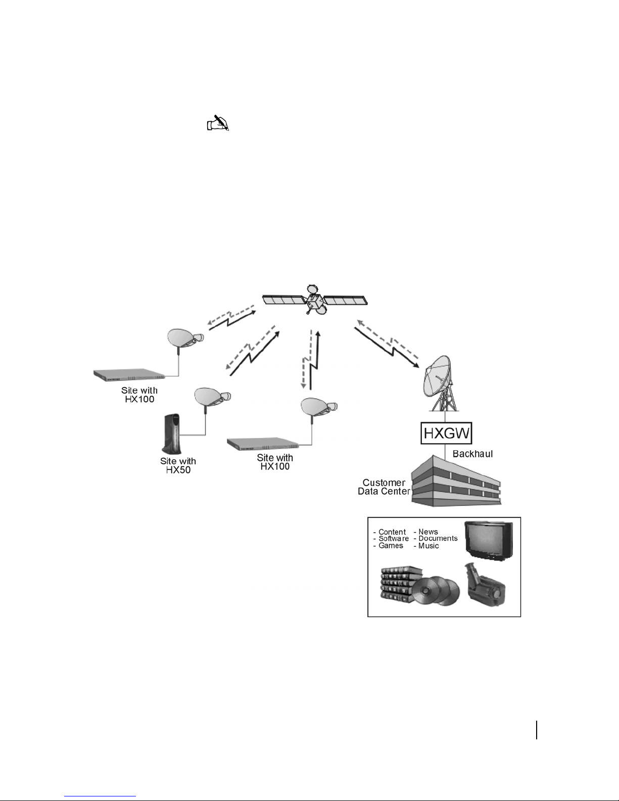
The HX network architecture is based on the TDM/TDMA star
topology. As shown in
Figure 1, the system can provide
high-speed Internet protocol satellite connectivity between the
corporate headquarters and multiple remote sites. The HX System
operates in the Ku, Ka, and C frequency bands.
Figure 1: HX System
Chapter 1 • Overview
1037852-0001 Revision A
5

Innovative features
The HX System provides many state-of-the-art features
including:
• Advanced bandwidth management capabilities – The HX
System allows operators to easily provision services like
constant bit rate (similar to single channel per carrier or
SCPC), minimum committed information rate (CIR) with
maximum limits, and best effort services. Plus, the HX
System can tailor these service offerings for each satellite
router.
• DVB-S2 – The HX System uses DVB-S2—the latest
generation satellite transmission standard. In its most basic
form, DVB-S2 incorporates 8PSK or QPSK modulation
together with low-density parity checking (LDPC). The
combination of 8PSK with LDPC produces approximately
30% more bandwidth than DVB-S for the same amount of
satellite power/bandwidth.
• Adaptive coding and modulation – The HX System
implementation of DVB-S2 supports adaptive coding and
modulation (ACM) in the outbound channel, allowing
operators to optimize the outbound channel for each satellite
router. For example, satellite routers in low EiRP regions can
be assigned robust coding and modulation combinations
(QPSK, Rate ½), while satellite routers in beam center can be
assigned bandwidth-efficient coding and modulation
combinations (8PSK, Rate 9/10). The application of ACM
produces up to 30% more bandwidth than DVB-S2, for a total
improvement of up to 60% over DVB-S.
• Most efficient TDMA return channel – Because HX
System TDMA return channels use Aloha for initial
assignment request, operators can optionally utilize the
bandwidth of satellite routers that are idle for some period of
time while maintaining the QoS commitment to a customer.
The HX System TDMA inbound channel also uses variable
length bursts, allowing up to 85% efficiency on the return
channel.
• Robust rain fade mitigation techniques – Recognizing that
high availability is a crucial element of enterprise SLAs, the
HX System provides the industry's most extensive set of
features for increasing overall system availability. These
features include dynamic ACM on the DVB-S2 outbound
carrier, dynamic coding of the TDMA return channel, and
dynamic uplink power control for the satellite router.
• Advanced IP features – HX satellite routers support a
number of built-in router functions, which are configured
remotely at the HX System gateway. These functions
Chapter 1 • Overview
6
1037852-0001 Revision A

generally eliminate the need for an external router at remote
sites. Router functions include flexible addressing with
support for routing information protocol (RIP), network
address and port translation (NAPT), port forwarding, DHCP
service and DHCP relay, DNS caching, and firewall
capability.
• PEP Data acceleration – All HX satellite routers implement
the Hughes PEP (performance enhancement proxy for TCP)
feature, which includes bidirectional TCP spoofing, data and
header compression, IP priority levels, ACK reduction, and
message multiplexing.
• Built-in network security – The HX System offers built-in
network security as a standard feature. All data transmissions
to satellite routers are encrypted to ensure that only
authorized modems access the transmission. Bidirectional
encryption is available as an option.
• Adaptive inroute selection (AIS) - A satellite router can
select an optimal symbol and coding rate for its inroute
transmission as a function of a configured trajectory table and
through information it learns about its transmission from a
closed loop power control algorithm. See the bulleted
description above for Robust rain fade mitigation
techniques.
• Cost-effective gateway – The HX gateway is optimized to
support small networks. It occupies a small physical space
and provides a very cost-effective solution for small
networks.
Broadband applications
HX Systems support the following services:
• Mobility - HX systems support the use of mobile satellite
routers through the use of the following primary enabling
technologies:
– Closed Loop Timing
– Spreading
– Doppler
• Broadband IP connectivity – The HX System offers a
completely private high-speed network with
performance-enhancing features that maximize performance
and network efficiency. The performance of individual
applications (interactive and file transfer) can be
independently managed with Hughes performance-enhancing
proxy parameters.
• GSM backhaul – The HX system can be configured as an IP
pipe and used as a global system for mobile communication
Chapter 1 • Overview
1037852-0001 Revision A
7

(GSM) backhaul to replace T1/E1 and other ground-based
base transceiver station-to-base station controller (BTS-toBSC) network elements.
• IP multicasts – The HX gateway supports IP multicasts to
send multimedia or other traffic to multiple remote sites
simultaneously, and HX satellite routers include IGMP
support to route IP multicast traffic to attached workstations.
• Border Gateway Protocol - BGP is a routing protocol
frequently used with MPLS networks. Utilizing BGP, the HX
now offers a more seamless interface to the networks.
HX System architecture
HX System star topology
HX gateway The HX gateway is the central processing center of the network.
The HX system provides star TDM/TDMA connectivity
consisting of a central gateway connecting to multiple HX remote
terminals. With a DVB-S/DVB-S2 outbound carrier supporting
rates up to 121 Mbps and multiple inbound carriers supporting
rates up to 3.2 Mbps, the HX system provides the high throughput
needed for high QoS networking.
The HX system star-topology network has the following major
elements, the HX gateway and the HX satellite routers.
The gateway provides connectivity between HX satellite routers
and customer data centers and/or the Internet.
The HX System supports two types of gateways:
• Fixed gateway
• Transportable gateway
Fixed gateway (GW)
The fixed gateway equipment is contained in one or more racks
that are in a fixed location.
The majority of this manual refers, by default, to the fixed
gateway system.
Chapter 1 • Overview
8
1037852-0001 Revision A
Transportable gateway (TGW)
The transportable gateway equipment is contained in a single rack
that can easily be packed, moved and reassembled.
The system is well suited for applications where network
transportability is critical - including homeland security,
continuity of operations, tactical military, and remote news
gathering. At only two feet in height, the system is a size and

cost-efficient solution to support the rapid deployment of smaller
satellite networks in difficult operating conditions.
A TGW overview with a description, list of features, services
supported, advantages and technical specifications is included in
Appendix B.
HX satellite routers HX satellite routers reside at the end user location and
communicate with the HX gateway via satellite link.
Network segments
The HX network is divided into segments, each of which
represents a portion of the communications link. These segments
include:
• Gateway segment
• Satellite router segment
• Space segment
• Wide area network segment
Gateway segment The gateway is the centralized earth station through which the
entire network is controlled. The gateway is normally located at
the customer's Network Operations Center (NOC). It contains
transmit and receive communications equipment, a radio
frequency terminal (RFT) consisting of RF equipment and a large
antenna, and network management subsystems and infrastructure.
The gateway segment manages the entire HX System and any
backend systems used for handling tasks such as billing, customer
care, and provisioning. See
Chapter 2 – Subsystems for more
information.
Satellite router segment Satellite routers provide broadband TCP/IP communications to
remote sites. The satellite router segment is the network segment
located at the end-user modems. Each satellite router has an
indoor unit (IDU), which contains the receive and transmit units;
and an outdoor unit (ODU), which consists of RF equipment and
an antenna.
Space segment The space segment is the satellite portion of the link, and
Wide area network segment The wide area network (WAN) segment includes the Internet and
A remote local area network (LAN) host is a device at the remote
site that communicates across the HX System via TCP/IP.
See Chapter 9 – Satellite routers, on page 69 for more
information.
connects all of the satellite routers in the network to the gateway.
various private independent IP networks with which HX satellite
Chapter 1 • Overview
1037852-0001 Revision A
9

routers communicate using TCP/IP protocol, including their host
computers.
The WAN segment also includes the commercial, off-the-shelf
(COTS) switches, routers, and other networking equipment
within the gateway that connect the gateway to the independent
IP networks.
System management
The network management system server (NMSS), also known as
Vision UEM, contains the set of management tools for HX
gateway primary components and interface equipment, including:
• IP gateway(s)
• Satellite gateway(s)
• DVB-S2 modulator
• Timing subsystem
• Inroute components:
– DNCC
–CDS
–Aurora CP
Minor components and equipment are managed through their
own interfaces. These components within the NMSS are:
• Element-management server
• Graphical user interface
• Backend database
• CACTI
For more information, see Network Management Support
Services (NMSS) subsystem on page 22.
10
Chapter 1 • Overview
1037852-0001 Revision A
See Chapter 3 – Network management for more information
about managing the HX System network.
Information flow
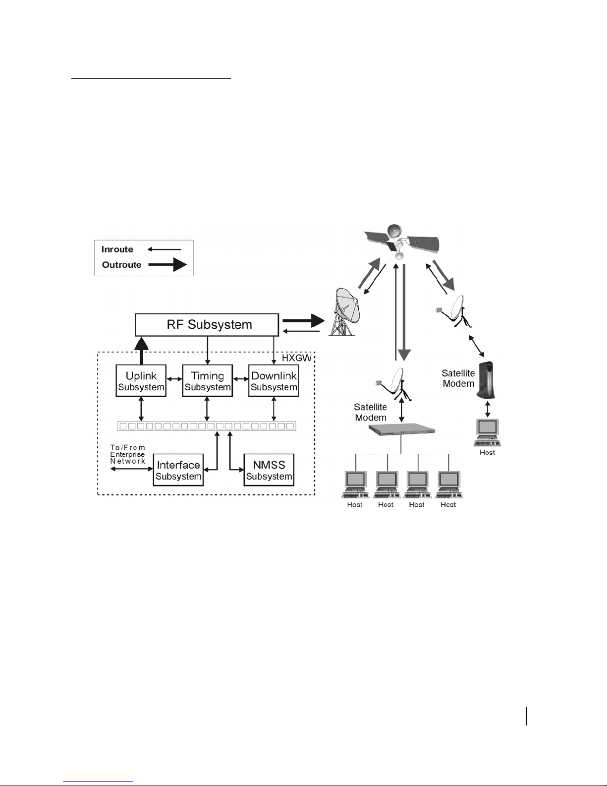
Figure 2 illustrates how information flows through the HX
System gateway equipment. Note the difference between the
arrows used to represent inroutes and those used to represent
outroutes. The differing widths of these arrows signify the
different bandwidths for data traveling from the HX gateway to
(outroutes or uplinks) and from (inroutes or downlinks) the
satellite modems.
Figure 2: HX System equipment data flow
Chapter 1 • Overview
1037852-0001 Revision A
11

12
Chapter 1 • Overview
1037852-0001 Revision A

Chapter 2
Subsystems
This chapter describes the subsystems that comprise the HX
system. These subsystems are standard with all Hughes systems
and are required for network operation.
This chapter includes:
• Interface subsystem on page 15
• Radio frequency (RF) subsystem on page 16
• Uplink subsystem on page 16
• Timing subsystem on page 18
• Downlink subsystem on page 19
• Network Management Support Services (NMSS) subsystem
on page 22
• Local area networks on page 25
The subsystems and the network connection are illustrated in
Figure 3 on page 14.
See Chapter 3 – Network management, on page 27 for a more
detailed discussion on Network Management.
Chapter 2 • Subsystems
1037852-0001 Revision A
13
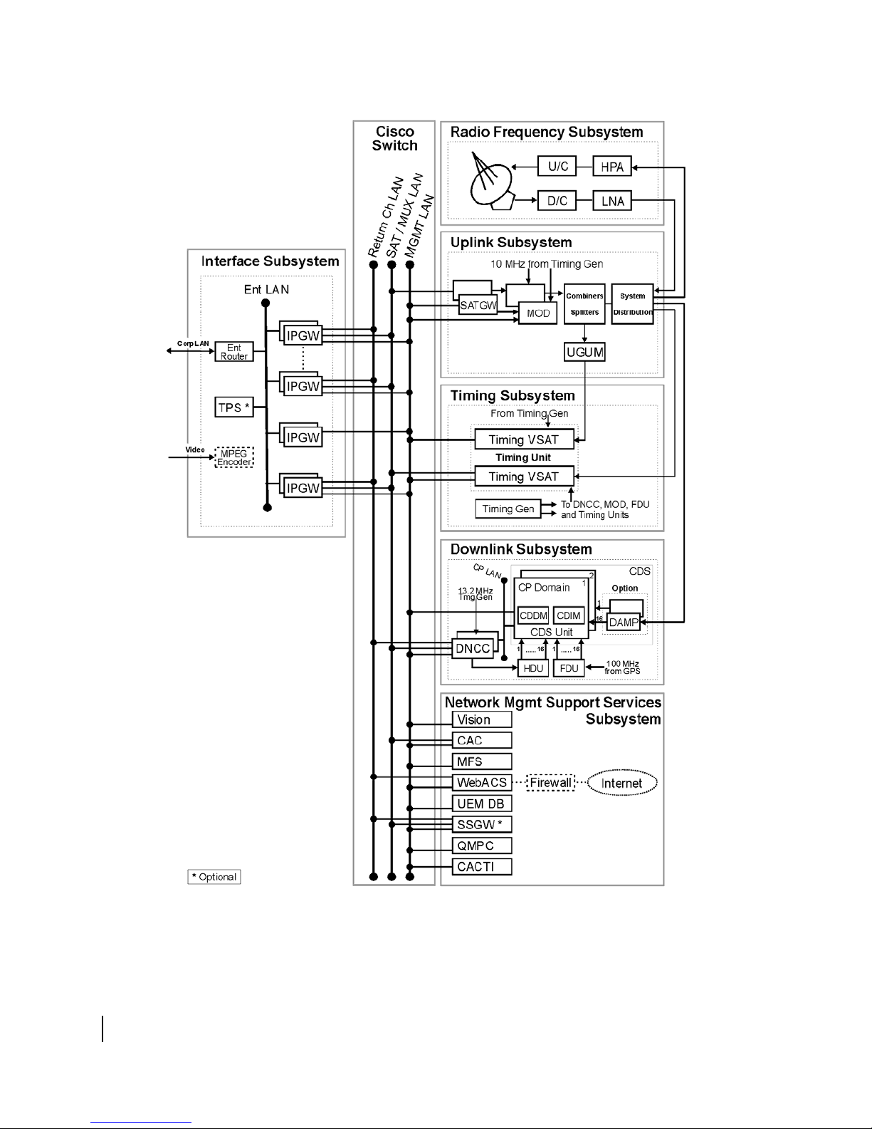
Figure 3: HX Subsystems and LAN Connections
14
Chapter 2 • Subsystems
1037852-0001 Revision A

Interface subsystem
The interface subsystem includes the IP gateway (core
component) and special services gateway (optional component;
described in Special Services Gateway (SSGW) Installation,
Operation, and Maintenance Manual (1032030-0001).
IP gateways
The IP gateways provides the interface between the HX gateway
and the enterprise intranet terrestrial data connections. The IP
gateway performs the IP address mapping, packet transmission,
compression, and other functions needed to support the HX
satellite routers. Traffic between the IP gateway and the intranet
host uses a standard IP packet format. However, the IP gateway
implements an Hughes-proprietary protocol between itself and
the satellite routers that is optimized for efficient, yet reliable
communication over the satellite link.
To facilitate data transfer from the IP gateway to the satellite
gateway, the IP gateway encapsulates unicast and multicast
frames containing traffic destined for satellite routers within User
Datagram Protocol (UDP) packets. The IP gateway obtains the
encryption information from the CAC, then encapsulates and
sends the appropriate unicast data and keys information to the
satellite gateway where the traffic stream is encrypted.
IP gateways forward the encapsulated unicast and multicast IP
traffic from the customer network to the satellite gateway over the
satellite LAN for further outroute processing. Unicast traffic is
addressed to a specific satellite router; multicast traffic is sent to
satellite routers in a pre-defined group and can include
management traffic or user traffic.
The IP gateways record statistics files that contain the amount of
traffic that has been processed for each IP subnet. IP gateways are
designed as a warm redundant pair with online and standby
modes of operation. IP gateways are SNMP-enabled and are
configured, controlled, and monitored by Vision UEM running on
the NMSS.
For TCP traffic, the IP gateway implements
performance-enhancing proxy (PEP) features. See
Enhancing Proxy (PEP V3) on page 52 for a description of the
PEP feature.
The IP gateway functionality also includes support for
multicasting services. In this mode of operation, the IP gateway
forwards multicast data (such as multimedia and advertising
content) through the satellite gateway to the remote sites that are
enabled (using the conditional access system) to receive the
multicast stream. Additionally, each IP gateway can also be
Chapter 2 • Subsystems
1037852-0001 Revision A
Performance
15

configured with a maximum total CIR to limit the IP traffic to the
customer's contracted grade of service.
Depending on the size of the network, there may be many IP
gateways within a single HX System gateway. Typically, the HX
gateway contains at least one IP gateway for each inroute
subsystem.
Radio frequency (RF)
subsystem
Radio frequency terminal
Uplink subsystem
The RF subsystem performs the actual transmission and reception
of satellite signals. The RF subsystem delivers received satellite
signals to the inroute subsystems at RF. It takes outroute signals
in the DVB asynchronous serial interface (ASI) format and
modulates and transmits those signals. The RF subsystem is
managed via SNMP using the management LAN and is internally
redundant. The RF subsystem consists of the radio frequency
terminal (RFT) and the system IF distribution module, which use
commercial, off-the-shelf equipment.
The RFT takes the uplink intermediate frequency (IF) output of
the system IF distribution module, upconverts it to radio
frequency (RF) and transmits it to the satellite. The RFT also
receives from the satellite the RF echo of the transmitted signal,
along with the RF input for the inroutes, downconverts the signals
to IF and forwards the downconverted signals to the system IF
distribution module and then to the downlink subsystem. The
RFT is made up of commercial off-the-shelf products.
The uplink (or outroute) subsystem performs the multiplexing
and transmission of all outbound IP traffic. All outbound traffic is
formatted to conform to the DVB-S or DVB-S2 standard.
16
Satellite gateway
Chapter 2 • Subsystems
1037852-0001 Revision A
The outroute subsystem is made up of satellite gateways, DVB
modulators, and outroute redundancy equipment.
The satellite gateway (SATGW) receives bundled satellite traffic
from the other NOC components over a LAN segment, formats
the information into individual packets, and forwards them to the
DVB modulator for transmission over the satellite.
The satellite gateway receives bundled satellite traffic over the
satellite LAN from the following components:
• IP gateways (including management gateways)
• DNCCs
• Special services gateways (SSGW)

• Timing unit (TU)
• Conditional access controller (CAC) server
Satellite gateways can receive encapsulated traffic using multicast
addressing.
The maximum length of the packets is configurable for each IP
gateway. A maximum expected frame length is also configured
into each satellite gateway and must be at least as large as the
largest corresponding value configured in the IP gateways feeding
that satellite gateway. The UDP frames are all destined to a single
IP multicast address. The frames contain sequence numbers and
other header information and one or more user traffic frames.
Multicast traffic is received over the satellite gateway multicast
address. This multicast address is unique across transponders.
The conditional access (CA) key traffic is received over the CAC
multicast address. This address is common to all satellite
gateways configured in the NOC. The common CAC address and
the unique satellite gateway address allow a single LAN
configuration to support multiple transponders. All traffic to the
satellite gateway is sent via multicast. The satellite gateway can
receive traffic on multiple (a maximum of 8) multicast addresses.
DVB and DVB-S2
modulators
Each satellite gateway connects to a DVB or DVB-S2 modulator.
The modulators are paired to satellite gateways and are designed
to switch together as a chain in the event of a failure. The DVB
modulators provide a 70 MHz IF output that is fed into an
outroute redundancy module and then onto the uplink system of
the RF terminal.
Two standards are supported, DVB-S and DVB-S2. Modulators
can be configured to support DVB-S only or both standards.
• DVB-S supports Reed-Solomon coding and QPSK
modulation
• DVB-S2 supports LDPC coding in both QPSK and 8PSK
modulation.
The modulator supports the following symbol rates:
• In DVB-S mode, the DVB modulator supports the following
symbol rates: 1.25, 2.5, 5, and 10 - 45 Msps, using FEC rates
up to 7/8.
• In DVB-S2 mode, the DVB modulator supports symbol rates
of 1–45 Msps in 1 Msps increments. The supported FEC rates
depend upon the frame length (short codeblock or normal
codeblock) and type of modulation:
– Short, QPSK modulation: 1/2, 3/5, 2/3, 3/4, 4/5, 5/6, 8/9
– Short, 8PSK modulation: 3/5, 2/3, 3/4, 5/6, 8/9
Chapter 2 • Subsystems
1037852-0001 Revision A
17

– Normal, QPSK modulation: 1/2, 3/5, 2/3, 3/4, 4/5, 5/6, 8/9,
9/10
– Normal, 8PSK modulation: 3/5, 2/3, 3/4, 5/6, 8/9, 9/10
DVB-S2 supports either CCM or ACM mode:
• In CCM mode, all satellite routers in the network operate at
the configured modulation rate, symbol rate, and FEC rate.
• With DVB-S2 operating in ACM mode, satellite routers can
adapt their FEC coding rate and modulation type (QPSK or
8PSK) to maximize the downlink speeds for the current
operating environment.
The DVB modulators are commercial off the shelf (COTS)
products.
Outroute redundancy
Timing subsystem
Timing generator
Timing unit
For the redundant configuration, outroute redundancy is
implemented to switch the SATGW/DVB modulator chain. The
functionality of monitoring the outroute and commanding a
switchover is implemented by the quality monitor PC (QMPC)
software component.
The timing subsystem provides the master timing for the entire
system. It also maintains the timing synchronization between the
NOC and the satellite routers. This subsystem consists of the
timing generator, the timing unit and the closed loop timing
(CLT) feature.
The timing generator provides the reference clock frequencies to
several NOC components, including both outroute modulators,
the timing unit, the optional automatic cross-polarization (ACP)
spectrum analyzers, and the DNCCs. It also generates a
superframe pulse for the DNCCs, the RCDs (older systems), the
timing unit, and the radio frequency terminal (RFT).
The timing unit provides return channel timing support for a
specific outroute. The timing unit consists of a pair of timing
satellite routers, one of which is configured as a superframe
numbering packet (SFNP) transmitter. The timing unit also
provides timing information for the optional ACP subsystem.
18
Chapter 2 • Subsystems
1037852-0001 Revision A
A timing unit measures the difference in time between the L-band
looped back signal and the signal looped back from the satellite
and provides TDMA timing information to the satellite return
channel terminals and the DNCCs within the downlink
subsystems accessible from terminals receiving this outroute.

Closed loop timing
The CLT feature provides timing adjustment feedback to enable
the satellite router to transmit as close as possible to the middle of
the burst aperture.
For more information see Closed loop control on page 65.
Timing subsystem physical
constraints
Downlink subsystem
Configurable Demodulation
Subsystem
A timing generator supports:
• Ten 10 MHz coaxial connectors thereby supporting up to 8
DVB modulators or ACP systems. Two per outroute and one
per ACP system (if added) are required.
• Eight DNCCs.
• Six timing VSATs.
The HX gateway can be configured with one or more inroutes.
Each inroute is a time-division multiple access (TDMA) return
channel. The inroute subsystem manages the return channels
associated with a group of satellite routers.
This system release features the introduction of the CDS, which
replaces the IFSS-TC in newer systems.
The CDS is a powerful digital signal processor that demodulates
one or more carriers, performs error corrections, and forwards the
resultant bursts to a NOC component.
A CDS consists of a single cardset, configurable demodulation
decoder module (CDDM) and configurable demodulation
interface module (CDIM). The CDS is hosted on a CompactPCI
(cPCI) chassis, along with a host control processor (CP) that is
connected to the dynamic network control cluster (DNCC)
through a LAN interface. The DNCC interfaces with the NOC
components via multiple LANs. The CDS receives inroutes from
the RF equipment and timing from the timing components. The
inroute bursts are processed by the CDS (demodulated and
decoded) and passed on to the DNCC. After converting inroute
bursts into IP packets, the DNCC passes the inroute traffic onto
the final destination, such as the corporate LAN or the Internet
via the internet protocol gateway (IPGW).
The CDS is completely compatible with DNCCs that interface
with Aurora return channel CPs.
One CDS platform can handle up to 9 inroutes, which can vary
based on whether a type 1 or type 4 board is used, across a
frequency band up to 36MHz wide, in a single 1U chassis.
The term CDS can refer to one or more instances of the CDS
platform.
Chapter 2 • Subsystems
1037852-0001 Revision A
19

CDS replaces the IFSS-TC, which shipped with older systems.
Furthermore, while the introduction of CDS is an upgrade, HX
systems continue to support both CDS and IFSS-TC.
CDDM The CDDM is a 6U wide module that plugs into one of the I/O
slots in the front of a cPCI chassis.
CDIM The CDIM is a 6U wide module that plugs into one of the I/O
slots in the rear of a cPCI chassis. The CDIM card accepts a
wideband IF input signal containing one or more inroutes,
centered at 70 MHz with a bandwidth of 36 MHz from the
external NOC equipment.
IF Subsystem-Turbo Code
system
In place of the CDS, most older systems have the IFSS-TC.
The IF Subsystem-Turbo Code (IFSS-TC) is a modular system
that:
• Acts as the HX gateway satellite radio receiver.
• Demodulates and decodes inroute signals received from
remote user modems via the satellite.
A typical redundant configuration includes:
• Up to two compact peripheral component interconnect (cPCI)
chassis, that contain storage media, power supplies, control
processors (CPs), CP transition boards, and RCDs that
contain software radio modules (SRMs) and receive control
modules (RCMs)
• One optional frequency distribution unit (FDU)
• Up to two intermediate frequency distribution units (IFDUs)
• One optional HNS timing control (HNSTC) distribution unit
(HDU)‘
A nonredundant system contains one cPCI chassis.
Return channel components The NOC can be configured with one or more TDMA return
channel subsystems (TRCSs). The TRCS manages the return
channels associated with a group of satellite modems.
20
Chapter 2 • Subsystems
1037852-0001 Revision A
Return channel demodulator
The RCDs provide the demodulation of the TDMA burst return
channels. The RCD accepts the inroute data, extracts the traffic
data, and gives the traffic data to the DNCC. The RCD consists of
the SRM and RCM.

Return channel control processor
The return channel CP is a Pentium III single-board computer in
the cPCI chassis that manages the RCDs. Depending on the NOC
rack configuration, there may be 1, 2, or 4 CPs in a system.
Return channel IF distribution
The return channel IF distribution module receives the IF output
from the system IF distribution module and forwards it to the
RCDs.
Dynamic network control
cluster (DNCC)
The dynamic network control cluster (DNCC) performs all the
processing and control functions of the inroute subsystem. The
DNCC manages return channel bandwidth. The DNCC receives
traffic bursts and control bursts. The traffic bursts contain modem
IP traffic as well as “piggybacked” bandwidth requests. The
control bursts can contain modem status, bandwidth requests, or
ranging information. Ranging is used to adjust the operational
parameters of a site and to fine-tune the satellite router's timing
and transmit power without the need for user intervention. If the
DNCC requests that the satellite router enter ranging mode, the
satellite router uses its assigned ranging burst. Based upon these
measurements, the site chooses the proper settings to transmit
traffic to the DNCC.
The DNCC processes each type of burst and constructs IP
packets, which are forwarded to the IP gateways. Different
bandwidth allocation algorithms are implemented on the DNCC.
Additionally, the DNCC generates the frame timing messages and
forwards them to the timing components.
The DNCC is simple network management protocol
(SNMP)-enabled and is configured, controlled and monitored by
Vision UEM running on the NMSS.
Control Processor To maximize efficiency when processing traffic, each inroute
The DNCC maintains detailed logs on all events pertaining to the
downlink subsystem. These include ranging/commissioning
information, inroute packet statistics, and other relevant data.
Redundant HX gateways contain two DNCCs configured as a
warm redundant pair with primary (online) and secondary
(standby) modes of operation.
defined at the DNCC is assigned an inroute group. All inroutes in
the same group are managed by the same CP. The number of
inroutes differs between CDS and IFSS-TC (older systems).
Chapter 2 • Subsystems
1037852-0001 Revision A
21

Systems with CDS
In newer systems with CDS and one BPE FPGA on the CDDM
board, each CP can support the following:
Table 1: CP support for systems with CDS
Symbol Rate
(for all active inroutes)
256 KSPS 1 9
256 KSPS 4 9
512 KSPS 1 4
512 KSPS 4 9
1024 KSPS 1 2
1024 KSPS 4 9
2048 KSPS 1 1
2048 KSPS 4 4
CDDM Board
Type (Number of
BPE FPGA's)
Maximum
active
inroutes
Systems with IFSS-TC
In older systems with IFSS-TC, each CP can support the
following:
• 12 inroutes, 256/512 ksps Turbo BCH at 1/2, 2/3, and 4/5
forward error correction (FEC) rate
• 6 inroutes, 1024 ksps Turbo BCH at 1/2 and 4/5 FEC rate
• 3 inroutes, 2048 ksps Turbo BCH at 1/2, 2/3, and 4/5 FEC
rate
Network Management
Support Services
(NMSS) subsystem
22
Chapter 2 • Subsystems
1037852-0001 Revision A
RCDs are housed in a cPCI chassis. The HX gateway rack can
support either one or two cPCI chassis, with three RCDs per
chassis. Each RCD can support a single inroute type
(combination of symbol rate, FEC rate, and coding type).
The NMSS is the name given to the functional elements running
in the NMSS (network management and support services) server.
These elements are:
• Vision - provides configuration and control interface for
many of the NOC components
• Conditional Access Controller - provides access control for
information transmitted through the HughesNet service
• Management file server (MFS) - provides a repository for
software and configuration parameters to be downloaded to
NOC components

• Web-based auto-commissioning - provides commissioning
services for satellite routers
• UEM database - stores all network configuration data
• Special services gateway - (optional) acts as an IP gateway
for satellite routers before they are commissioned, and
provides bandwidth broker services for the downlink
• Quality Monitor PC - receives satellite output and monitors
the quality
• CACTI - network monitoring and event logging
Vision
Conditional access
controller
Management file server
Vision provides a software interface to monitor, configure, and
control network components, including satellite routers and NOC
components.
The conditional access scheme prevents the reception of traffic
belonging to a different customer. The CAC uses encryption
technology to protect the user against unauthorized access. The
CAC components perform the key management for the unicast
TCP/IP encryption and IP multicast conditional access. Typically
a single multicast IP address is used; however, a scaling feature
that uses multiple multicast addresses is also available for large
networks.
The management file server (MFS) is both a repository and a
component controller. It is a repository for software downloads
and parameter files for managed NOC components. It also
controls the enable/disable functions of NOC components and
notifies those components of the file and version information and
updates.
MFS relies on the management gateway client (MGC) service
that is installed on each managed component. The MFS sends
periodic heartbeat messages to the MGCs on these components
using broadcast or multicast. If the MGC on a particular
components determines that new software or configuration files
are needed, it downloads these files from the MFS using FTP.
Web-based
auto-commissioning
Vision copies files into MFS using FTP/Windows file sharing and
notifies the MFS of any newly uploaded files using SNMP.
When a satellite router is installed, certain information must be
provided to the NOC operator to ensure the site is commissioned
properly. Auto-commissioning automates the commissioning
process with no intervention by the NOC operator to provide fast
turnaround on satellite router installations and prevent
configuration mistakes. WebACS also configures components
necessary for older generation equipment.
Chapter 2 • Subsystems
1037852-0001 Revision A
23

Auto-commissioning can take place over the Internet or the
satellite link using the web-based auto-commissioning server
(WebACS).
Satellite-based commissioning Satellite-based commissioning (SBC) is a optional feature that
allows an operator to commission the installation without using a
phone line to contact the WebACS. This method automatically
establishes TCP connectivity between the client and NOC
components.
SBC implements various approaches to enable this to occur.
Some of the important techniques used to enable this are as
follows:
• The source IP address configured in the TCP/IP stack can be
the same for multiple PC's that are commissioning
simultaneously
• The default gateway IP address for all commissioning PC's
will be the same
• The DNS server IP address can be any private address
reserved by HNS since DNS lookups are proxied in the NOC
during SBC
The SSGW is the major NOC component of the SBC process.
UEM database
Special services gateway
Quality monitor PC
SBC is not available with the TGW-100.
The unified element management (UEM) database contains
configuration information for these services, maintained under a
separate schema for each. The NOC Forms application provides a
configuration interface for CAC, WebACS, while Vision contains
its own interface. The MFS is configured using an ASCII text file.
The special services gateway acts as the IP gateway for satellite
routers that are not yet commissioned. The special services
gateway is optional, but required for using the WebACS feature.
The SSGW is not an option on the Transportable Gateway
(TGW) model.
The QMPC, with help from the SNMP interface, receives the
satellite gateways modulated output and monitors its quality,
posting alarms and initiating satellite gateway switchover as
appropriate.
Used in redundant systems only, the QMPC ensures that only one
SATGW-DVB modulator chain passes traffic at any given time.
The SATGW-DVB modulator chain to pass traffic can also be
selected manually by the HX gateway operator.
24
Chapter 2 • Subsystems
1037852-0001 Revision A

The QMPC resides on the NMSS server and has the ability of
supporting multiple transponders (up to eight outroutes).
Note: The nonredundant HX system configuration does not
contain a QMPC.
CACTI Network Manager
Local area networks
Gateway LAN
Management VLAN The management LAN connects the network management
CACTI Network Manager (new installations only) provides for
network monitoring, event logging, and graphing SNMP
statistics. Templates for network devices are included with this
feature.
The HX systems use LANs and VLANs to simplify connections
and reduce cable clutter. The following list indicates the functions
of the individual LANs/VLANs within the system.
• Gateway LAN
– Management VLAN
– Satellite or MUX VLAN
– Return channel VLAN
– Control processor (CP) VLAN
• Enterprise LAN/VLAN
The gateway LAN is used for internal communications and
consists of four VLANs.
subsystem to other subsystems.
The management LAN carries all NOC administrative messages,
including managed NOC component software and configuration
information.
Satellite VLAN The satellite LAN connects the multicast broadcasters to the
multiplex (MUX) subsystem.
The satellite LAN carries outroute traffic destined for satellite
routers from the IP gateway, management gateway, dynamic
network control cluster (DNCC), timing unit, and conditional
access controller (CAC).
The satellite gateway receives the traffic on the satellite LAN and
sends it on the outroute. The satellite also sends flow control
information to all the IP gateways on the satellite LAN.
The satellite LAN is a dedicated LAN, which makes it easier to
troubleshoot in cases of packet loss.
Chapter 2 • Subsystems
1037852-0001 Revision A
25

The Satellite LAN is also referred to as the Multicast or MUX
LAN.
Return Channel LAN The return channel LAN allows the DNCC to forward received
inroute packets to the IP gateways in the uplink subsystem. The
DNCC transmits these packets into the return channel LAN.
CP VLAN The CP LAN carries inroute control messages, such as burst time
plans, from the DNCC to the CDS (or the IFSS-TC). It also
carries user traffic from the CDS (or the IFSS-TC) to the DNCC.
Enterprise LAN/VLAN
The enterprise LAN carries user and management traffic from the
IP gateways to the customer’s enterprise router or the internet.
The enterprise LANs connect an uplink subsystem to the
independent IP network accessible by terminals receiving the
subsystem's uplink in such a way that the traffic from one
independent IP network is accessible only by a terminal
authorized to access that network. The downlink subsystem also
requires access to these enterprise LANs so that it can forward
inroute packets to the associated equipment within the
appropriate uplink subsystem.
The enterprise LAN is also referred to as the INET LAN.
26
Chapter 2 • Subsystems
1037852-0001 Revision A

Chapter 3
Network management
This chapter describes the network management functions.
• Overview on page 27
• Configuration management on page 29
• Fault management on page 31
• Performance management on page 32
• Security management on page 32
• Component control on page 34
Overview
Network management provides management tools for HX System
gateway components and interface equipment, including:
• IP gateway
• Timing unit(s)
• Satellite gateway
• DVB modulator
• DNCC
• CP
• CDS (or IFSS-TC in older systems)
All other network components and equipment are managed
through their own interfaces.
Figure 4 illustrates the network management system architecture
and how it connects to other HX gateway components.
Chapter 3 • Network management
1037852-0001 Revision A
27

Figure 4: Network management system and LAN connections
28
Chapter 3 • Network management
1037852-0001 Revision A

NMSS server components
The HX gateway incorporates four major network-management
components within a single high-performance server:
• Element-management server
• Graphical user interface (GUI)
• Back end database
• CACTI
These components enable the HX gateway operator to perform
both network operations (such as monitoring network status and
statistics) and overall network management activities (such as
configuration and control).
Configuration
management
Gateway component
configuration
Remote site component
configuration
NMSS configures satellite routers and some of the HX gateway
components. The network configuration is stored in the UEM
database, and operators can maintain it either through the Vision
graphical user interface (GUI) or provision components using a
batch mode facility. In addition, Vision provides a commissioning
interface to the Web-based auto commissioning system
(WebACS) to support the auto-commissioning of satellite routers.
NMSS generates configuration files for each Vision-managed
gateway component as needed, and sends them to the MFS
component of the NMSS server. The MFS acts as a central
repository for all configuration and software files for
Vision-managed gateway components. Each gateway component
managed by Vision contains a management gateway client
(MGC). MGC is in constant communication with MFS using a
proprietary protocol. the MGC downloads configuration files
from MFS.
NMSS also generates configuration files for remote site
components. It communicates with remote components through a
specialized mechanism called software download (SDL), which
informs the components of changes in required files. The SDL
protocol permits files to be delivered in both push (sent
unilaterally by NMSS) and pull (requested explicitly by the
modem component) modes. In addition, NMSS uses a multicast
delivery mechanism to transmit shared files simultaneously to all
modem components that need them, thereby conserving outroute
bandwidth. Files that are not shared between components are sent
via unicast delivery.
Profiles and profile groups
To simplify the task of managing the many different
configuration parameters available in the HX System, NMSS
provides conceptual groupings of related parameters called
Chapter 3 • Network management
1037852-0001 Revision A
29

profiles. Profiles are generally organized by function or feature,
and can be of two types: shared and unique.
• Shared profiles can contain such parameters as resource
allocations and tuning parameters, which are often shareable.
Operators can create shared profiles and manage them
independently of any particular network component.
• Unique profiles contain parameters, such as interface
addresses, whose values cannot be shared because they must
be specific to a component.
Most shared profiles are optional profiles. Profiles containing
parameters that must be configured on a device are considered
mandatory profiles. Profiles containing critical values that should
be changed only by a network administrator are considered
restricted profiles. A network administrator can determine which
profile types are considered restricted.
Because the large number of optional features can make even the
management of profiles tedious, NMSS provides an even higher
level of conceptual grouping called the profile group. A profile
group is simply a collection of shared profiles that can be
associated with a component as a set. A remote site component
can be associated with one core profile group, which is assigned
by a network administrator, and optional customer profile groups,
which can contain profiles that are not restricted.
Software configuration
management
Configuration interfaces
NMSS supports the ability to remotely install and upgrade
software images on both gateway and remote site components.
Software profiles are used to manage software versions. Vision
distributes software files to gateway and modem components
using the same mechanisms used to distribute configuration files.
Software images for modem components are multicast via SDL.
NMSS provides a number of interfaces through which network
configuration can be defined and maintained.
The NMSS graphical user interface (GUI) is the interactive
interface that operators use to perform initial network definition
and the creation of profiles, users, and hub components, as well as
other administrative tasks. The GUI provides full manual control
of all configuration parameters and system settings, subject to
configured operator access policies and restrictions. HX gateway
personnel can use the GUI, as can customers at remote sites and
customer support agents.
NMSS also has a provisioning interface intended for batch-mode
definitions of remote site components. The provisioning tool
extracts a list of sites to be provisioned from an extensible
30
Chapter 3 • Network management
1037852-0001 Revision A

markup language (XML) formatted file and updates the Vision
UEM database with the site definitions and configurations. A
typical use of this tool is the integration of a service provider's
order-entry system. For better integration with desktop tools,
there is also a utility to convert comma-separated value
(CSV)-formatted files into XML.
Finally, NMSS provides a commissioning interface that is used
by the WebACS during the auto-commissioning process.
Fault management
Status monitoring
Fault management functions provided by NMSS include status
monitoring, reporting, and alarms.
Vision monitors the status of gateway and remote site network
components through simple network management protocol
(SNMP) and proprietary Hughes protocols. All managed HX
network components have embedded SNMP agents that can
report status and statistics information to a suitably configured
SNMP manager.
Vision uses SNMP to periodically obtain key status information
from gateway components. It can also query remote site
components periodically for key status information, although this
capability can be disabled to conserve network resources. Vision
can use an alternate mechanism–the VSAT information protocol
(VIP)–when available, to get status information from remote sites
more efficiently.
Current status information is displayed on the Vision UEM GUI
through color-coded icons. The GUI also provides fault-isolation
capabilities that operators and customer support agents can use to
troubleshoot and diagnose faults. The diagnosis functions use
real-time SNMP queries to report up-to-date information from
network components.
Alarms
HX network components with SNMP agents generate SNMP
traps when certain error conditions occur, and send them to a
configurable trap IP address. The traps generated by network
components are documented in the SNMP management
information base (MIB) definitions for those components.
To assist in the detection of failed sites or specific patterns of
network failures, NMSS can generate certain alarms in the form
of SNMP traps. For example, a component alarm can be
generated when a remote site has been down for a configured
period of time, and an aggregate alarm can be generated when the
number or rate of failures of components in a specific group
exceeds a configured threshold.
Chapter 3 • Network management
1037852-0001 Revision A
31

Performance
management
NMSS provides both real-time and historical statistics on
network components and traffic. These statistics are obtained by
querying components through SNMP.
Real-time statistics
Historical statistics
Security management
Operator security
Real-time performance reports are shown through the Vision
UEM GUI. Detailed statistics, which are updated periodically,
can be displayed on every managed network component. The
display formats can be changed dynamically to show absolute
values, relative values, deltas, or rates. NMSS also has an
integrated graphing tool called FlexGraph that can be used to
build an ad hoc graph of selected statistics to display trends in
real time.
The historical statistics collection feature enables users to define
ad hoc sets of statistics to be sampled periodically and saved in a
disk file. NMSS can run the sampling operations between a
specific range of times, and save the results in a comma-separated
variables (CSV) formatted file. This facility can be used for
long-term trend analysis.
NMSS provides mechanisms for operator security, network
component security, and encryption key management.
NMSS controls all access to network management features by
user-level authentication. All interfaces, whether interactive,
batch-mode or programmatic, are protected by a user id/password
login sequence.
32
Network component
security
Configuration NMDs Vision supports logical partitioning of the network into
Chapter 3 • Network management
1037852-0001 Revision A
There are two classes of users defined. Privileged users have
unrestricted rights. They can define other users, assign access
rights for those users, and perform other supervisory and
administrative functions. Unprivileged users can only perform
actions for which access rights have been granted to them.
The network is logically partitioned into network management
domains (NMDs):
• Configuration NMDs
• Management NMDs
Each operator can be associated with one or more NMDs, thus
restricting that operator’s access to network devices only in the
assigned NMDs.
non-overlapping domains called configuration NMDs.

Partitioning is performed at the network device (satellite router or
HX gateway component) level.
When a network is installed, one NMD, called the default NMD,
is automatically provided. Each device belongs to exactly one
NMD.
Management NMDs To limit the number of service offerings that must be managed
and maintained, all value-added resellers (VARs) are presented
with the same set of service offerings (and therefore, profile
groups). Because profile groups are linked to NMDs, all satellite
routers belonging to VARs must reside in the same NMD in the
NMSS.
To allow each individual VAR to monitor and control its own
satellite routers, yet prevent them from accessing other VAR’s
satellite routers, NMSS provides a management NMD that may
be assigned to each satellite router. Operators can then be
assigned to a management NMD.
Management NMDs differ from configuration NMDs in three
important aspects:
• A management NMD is optional for a satellite router.
• Any operator assigned to a management NMD may ONLY be
granted monitor and control privileges to those satellite
routers within the management NMD.
• No configuration privileges may be granted to any operator
within a management NMD.
Encryption key
management
The management of traffic encryption keys is performed by the
UEM/CAC. See
For more information, see Chapter 4 – Network
security.
Chapter 3 • Network management
1037852-0001 Revision A
33

Component control
NMSS can send commands to network components using SNMP
for actions such as resets, reboots, and forced reloads of software
configuration.
HX gateway control
Remote site control
You can send commands to the following HX gateway
components:
• IP gateway (IPGW) / satellite gateway (SATGW)
• MFS (resides on the NMSS server)
• DNCC
• CP
• CDS
You can send commands to the satellite routers at remote sites.
34
Chapter 3 • Network management
1037852-0001 Revision A

Chapter 4
Network security
This chapter describes the data security features in the HX
System. These features guarantee data integrity and
confidentiality, and protect the network from intrusion and
external exploits. The following topics are presented:
• Data encryption on page 35
• Network security features on page 36
Data encryption
DES-encrypted outbound
channel
The HX System can employ several information assurance
techniques to safeguard the integrity and confidentiality of data
transported through the system. These techniques include:
• DES-encrypted outbound channel
• Two-way IPSec encryption
The outbound channel is encrypted using the data encryption
standard (DES) by the HX CAS (conditional access system)
feature. This CAS feature:
• Is hardware-based
• Ensures that traffic is received by satellite routers legally
• Prevents unauthorized eavesdropping
The HX CAS feature assigns a unique key to each satellite router.
It is responsible for key management and for encrypting
outbound data to satellite routers to ensure that satellite routers
can only decrypt the data intended for them.
When a satellite router is commissioned, it requests its encrypted
effective master key (EEMK) from the HX gateway. This key is
sent to the satellite router, and then:
• Used at the HX gateway to encrypt all data sent to the
satellite router
• Used by the satellite router to decrypt all data received from
the HX gateway
Two-way IPSec encryption
Because all data transmissions to satellite routers are uniquely
keyed, a satellite router can decrypt only the data sent to it. The
EEMK is also used by satellite routers to authenticate themselves
to the HX gateway.
IPSec in the HX System is NIST for FIPS 140-2 level 1 certified
and has these characteristics:
Chapter 4 • Network security
1037852-0001 Revision A
35

• End-to-end encryption from satellite router to the endpoint on
the enterprise network using IPSec, Advanced encryption
standard (AES), and Internet key exchange (IKE) protocols
• Rides over top of the encrypted outroute and clear inroutes
• AES implemented in software
• TCP proxy is outside of the IPSec tunnel, preserving satellite
acceleration in a secure configuration
The HX System provides standards-based IPSec/IKE support for
encrypting user data traffic and managing encryption keys. The
IKE protocol is used to automatically generate and maintain
128-bit session keys and to set up an IPSec tunnel between a
satellite router and an IP gateway in the enterprise network. This
ensures that the data is encrypted end-to-end between the
customer's remote site and the enterprise network.
The HX System IPSec feature provides encryption without
affecting the TCP acceleration and prioritization features. (
See
Network layer features on page 51 for information about the TCP
acceleration and prioritization features.) The Hughes IPSec
Kernel is NIST certified.
Network security
features
Firewalling
The HX System provides the following network safeguards to
protect the HX gateway and the LANs connected to satellite
routers:
• Firewalling – A packet filtering firewall to protect LANs
connected to satellite routers
• Fenced Internet – URL white lists can be defined to restrict
web browsing from remote LANs to only permitted sites, IP
addresses, and domains.
Note: The HX system supports network address translation
(NAT) and port address translation (PAT)—features that can hide
the topology of LANs behind a satellite router to prevent
computers on those LANs from being directly addressed from the
Internet. See
feature
NAT/PAT on page 53 for information about this
Satellite routers have an embedded firewall. Firewall rules can be
defined in satellite router profiles at the HX gateway and
forwarded to satellite routers. There are also firewall
configuration and statistics web pages on the HX satellite router
System Control Center which, when enabled in HX gateway
profiles, can be used to create firewall rules at the satellite router,
and view firewall statistics. The HX satellite router firewall works
on inbound (outroute) traffic only.
36
Chapter 4 • Network security
1037852-0001 Revision A

Fenced Internet
The fenced Internet access (FIA) service is an option that requires
a TurboPage server. The FIA service provides a mechanism for
enterprise customers to restrict remote site access to a limited
number of specifically approved Internet sites. Different lists of
approved sites can also be supported for multiple subsets of a
customer's remote sites.
Chapter 4 • Network security
1037852-0001 Revision A
37

38
Chapter 4 • Network security
1037852-0001 Revision A

Chapter 5
Bandwidth management
Bandwidth management is the collection of techniques used in
the HX system to manage available bandwidth to the greatest
advantage. The HX system uses a variety of techniques to
manage bandwidth to maximize flexibility and adapt to
environmental conditions while providing guaranteed levels of
throughput to meet service level agreements (SLAs) or
demanding real-time media transport requirements.
The following sections describe the bandwidth management
techniques used in the HX system:
• Bandwidth management overview on page 39
• Inroute bandwidth pooling on page 40
• Advanced bandwidth management techniques on page 43
• Traffic prioritization on page 47
• Unlimited combination of service plans on page 49
Bandwidth management
overview
The HX System allows operators to customize bandwidth
assignments for each satellite router to meet individual QoS and
SLA requirements (as compared with the HN System that is
designed to provide a fair distribution of bandwidth across a
broad set of satellite routers within a collective system).
Additionally, the HX System uses variable burst length
transmissions for the inbound route. This is an advantage over
systems that use fixed burst length sizes. Such systems waste a
significant amount of bandwidth because every inbound burst
must be the same size, regardless of actual payload demands. The
Hughes HX System allows the return channel burst size to be
built optimally per satellite router, based on demand.
Extensive and repeated tests on the throughput of the Hughes
inbound system demonstrate inbound efficiency up to 85 percent.
In practical application, this means that the aggregate upstream
performance for a typical inroute easily reaches 85 percent of the
inbound channel rate; for example 1.3 Mbps aggregate upstream
throughput for a 1.6 Mbps return channel.
Chapter 5 • Bandwidth management
1037852-0001 Revision A
39

Bandwidth assignments
The HX System has the flexibility to provide two types of
bandwidth assignments:
• Nailed-up bandwidth - ensures that the bandwidth is
guaranteed and has low latency on start-up, but inefficient use
of the bandwidth may be experienced if the satellite router is
idle for long periods of time.
• Activity-based bandwidth - provides a more efficient use of
the overall bandwidth, but causes delay at the initial start-up
of traffic.
The system can operate in a mixed mode, for example, it can
provide some sites nailed-up bandwidth assignment while
providing other sites with bandwidth based on activity. In both
cases, there is the capability to dynamically adjust the assigned
bandwidth based on real-time traffic requirements.
Inroute bandwidth
pooling
To leverage the fact that all satellite routers within the HX System
are fully frequency-agile across all inbound channels, the HX
System bundles the inbound channels into a single large pool of
resources. At any point, a satellite router may be instructed to
access virtually any inbound channel. The channel accessed is
determined by the HX gateway dynamic network control cluster
(DNCC), which considers multiple factors, including the QoS
commitments of each satellite router.
40
Chapter 5 • Bandwidth management
1037852-0001 Revision A

Figure 5: Multi-frequency inbound access
To achieve the efficiencies of pooling (that is, to realize the
effects of the law of large numbers) while, at the same, providing
the quality of service committed for each satellite router, the HX
System uses a number of techniques. One important element is
the concept of inroute quality of service (IQoS) plans. An IQoS
plan is simply the logical partition of inroute bandwidth together
with the satellite routers that can access the logical bandwidth.
The assigned logical inroute bandwidth is designated as Open and
is typically used by satellite routers configured for dynamic
stream (otherwise known as best effort access).
Figure 6
illustrates the structuring of the inroute bandwidth.
Chapter 5 • Bandwidth management
1037852-0001 Revision A
41

Figure 6: Inbound pooling
An important element in the inbound allocation scheme is that
bandwidth need not be dedicated (that is, assigned to a specific
satellite router or group of satellite routers) but can instead be
guaranteed. The advantage of guaranteeing bandwidth is that
when an IQoS plan does not fully utilize its assigned bandwidth,
the HX System is free to reallocate this bandwidth to other IQoS
plans (allowing over subscription of bandwidth), providing
flexibility to an operator.
Dynamic stream services
42
Chapter 5 • Bandwidth management
1037852-0001 Revision A
When a satellite router is configured for dynamic stream services,
the amount of bandwidth it receives is based on a combination of
the following factors:
• Backlog amount – This is the satellite router’s estimation of
how much bandwidth it needs at any given amount.
• Available IQoS capacity – This is the amount of available
network capacity the system is using to allocate the dynamic
stream capacity for this IQoS plan.
The IQoS plan defines the maximum amount of bandwidth
available to a group of satellite routers as they access the dynamic
stream bandwidth. The HX System supports multiple IQoS plans,
allowing operators to provide different levels of best-effort
services to different groups of customers.

Advanced bandwidth
management
techniques
The HX System has advanced bandwidth management tools that
advise the operator how much outbound and inbound bandwidth
has been consumed by various CBR and CIR services, as well as
how much bandwidth is available for the best effort services.
These tools, which provide a variety of statistical and status
information, allow an operator to intelligently load the network
and understand to what extent the network is over-subscribed.
The CBR traffic is assigned the highest priority, followed by CIR
traffic. CBR and CIR are serviced before assignment of
bandwidth for best effort services.
Preassigned CBR services
Outroute CBR
With this bandwidth management scheme, satellite routers can be
configured (preassigned) to consume a fixed amount constant bit
rate (CBR), and this bit rate can be configured independently for
the outbound and inbound directions. For example, a satellite
router can be configured with a 512 kbps inbound CIR and a 256
kbps outbound CBR. Additionally, the satellite router can be
configured to deallocate the bandwidth if the channel has been
idle for a configurable period of time.
CBR services operate similar to single channel per carrier
(SCPC) links, as the assigned bandwidth per channel is fixed,
based on the configuration of the link.
Note: The idle timeout feature can be disabled in order to
configure nailed-up bandwidth assignment.
Statically configured Constant Bit Rate requirements (Hard QoS
configuration per VSAT):
• CBR traffic is assigned the highest priority, ahead of CIR and
Best Effort.
• The CBR bit rates values range from 32 Kbps to the IP
gateway CIR
• CBR users are not allowed to pass traffic in excess of the
CBR bit rate.
• CBR configuration specifies the bit rate on a per-remote
basis.
• The IP gateway supports remotes with different outroute
CBR requirements.
Adaptive CBR with step
increments
In this bandwidth assignment service, satellite routers are
allocated bandwidth based on the following parameters:
• Minimum CBR – The amount of bandwidth that will be
immediately allocated to a satellite router at the initiation of a
Chapter 5 • Bandwidth management
1037852-0001 Revision A
43

data session. This minimum CBR is low jitter, as the
bandwidth is assigned to the satellite router until the CBR
session terminates. Termination of the CBR session is based
on idle period.
Figure 7 illustrates the CBR feature of the HX
System.
• Maximum rate – The maximum amount of bandwidth that
the modem will be allocated.
• Threshold level – The level of usage at which the satellite
router will be allocated an additional fixed amount of
bandwidth (described in the Step increment bullet item).
The step-up threshold is a percentage of the currently
assigned bandwidth that, once reached, creates an increase
in the allocated bandwidth. The increase amount is
dictated by step-size.
The step-down threshold is a percentage of the currently
assigned bandwidth that, once reached, creates a decrease
in the allocated bandwidth. The decrease amount is
dictated by step-size.
The threshold level is defined as the following ratio:
Bandwidth Used by the Satellite Router
________________________________
Bandwidth Assigned or Allocated
For example, if the threshold level is 80%, when the
utilization level exceeds 80%, an additional step increment of
bandwidth is allocated to the satellite router. The utilization
or load of the channel is evaluated every 500 ms.
• Step increment – The fixed amount of bandwidth, in kbps,
that will be allocated to a satellite router as it requires more
than the minimum CBR amount. The HX System uses the
threshold level (defined above) to determine when to allocate
additional step increments. The HX System continues to
allocate step increments up to the maximum rate of the
modem or until the bandwidth of the inroute is exhausted.
The step-up threshold is a percentage of the currently
assigned bandwidth that, once reached, creates an increase
in the allocated bandwidth. The increase amount is
dictated by step-size.
The step-down threshold is a percentage of the currently
assigned bandwidth that, once reached, creates a decrease
44
Chapter 5 • Bandwidth management
1037852-0001 Revision A

in the allocated bandwidth. The decrease amount is
dictated by step-size.
• Session activity timeout – The period of IP inactivity after
which the session will be disconnected and the bandwidth
freed for use by other satellite routers.
Note: The idle timeout feature can be disabled in order to
configure nailed-up bandwidth assignment.
Figure 7: CBR services
In this bandwidth assignment service, satellite routers are
CIR
allocated bandwidth based on the following parameters:
• Minimum CIR rate – The amount of bandwidth that will be
immediately allocated to a satellite router at the initiation of a
data session. This minimum CIR is low jitter, as the
bandwidth is assigned to the satellite router until the CIR
session terminates. Minimum CIR bandwidth is prioritized
after configured CBR bandwidth. Termination of the CIR
session is based on idle period.
• Guaranteed CIR rate – The amount of bandwidth to be
allocated to a satellite modem when the satellite modem’s
bandwidth utilization exceeds the configured threshold
percentage of the minimum CIR value. When this occurs,
bandwidth allocation to the satellite modem is increased to
the configured guaranteed value.
Guaranteed CIR value is available only in the inbound
direction.
• Maximum CIR rate – The maximum amount of bandwidth
to be allocated to a satellite router when the advertised
backlog exceeds the configured guaranteed.
Chapter 5 • Bandwidth management
1037852-0001 Revision A
45

Figure 8: CIR services with best effort
Figure 8 illustrates the CIR with best effort service. In this access
mode, the satellite router is provided the guaranteed CIR the
moment traffic activity is detected. A satellite router is eligible to
receive bandwidth in excess of its guaranteed CIR up to its
maximum CIR based upon its advertised backlog, periodic, and
left-over bandwidth. The DNCC (the bandwidth manager element
in the HX gateway) provides the requested (or excess) bandwidth
in a best effort manner. If the bandwidth is available, it is granted
up to the maximum rate defined for the satellite router.
Outroute CIR
Statically configured CIR service requirements (Hard QoS
configuration per VSAT):
• CIR traffic is assigned a lower priority than CBR traffic and a
higher priority than best effort traffic.
• The CIR configuration specifies a minimum CIR (minCIR)
and maximum CIR (maxCIR) bit rates on a per-remote basis.
• The IP gateway supports remotes with different outroute CIR
requirements.
• The CIR bit rates values range from 32 Kbps to the IP
gateway CIR.
• CIR users are not allowed to pass traffic in excess of maxCIR
bit rate.
• CIR users with a CIR level between the minCIR and the
maxCIR bit rate are serviced as best effort users, but the
traffic is sent at CIR users traffic priority.
46
Chapter 5 • Bandwidth management
1037852-0001 Revision A

• Servicing of CIR users with CIR level between the minCIR
and the maxCIR bit rate should not be at the expense of CIR
users with CIR level below their respective minCIR.
• Outroute multicast traffic is not included in the computation
of users’ CIR levels.
Best effort services
Bandwidth terminology
A satellite router that is configured for best effort services is
eligible to receive backlog, periodic, and left-over bandwidth.
When a satellite router is configured for best effort services, the
amount of bandwidth it receives is based on the backlog amount.
This is the satellite router’s estimation of how much bandwidth it
needs at any given amount.
Best effort users can be assigned (optionally) to an IQoS plan.
The IQoS plan defines the maximum amount of bandwidth
available to a group of satellite routers as they access the dynamic
stream bandwidth. The HX System supports multiple IQoS plans,
allowing operators to provide different levels of best effort
services to different groups of customers.
Best effort utilizes the remaining bandwidth after meeting the
requirements for guaranteed CBR and CIR bit rate services.
Operators need to be familiar with the following bandwidth
related terms:
• Backlog - the estimated amount of data queued in a satellite
router that is awaiting to be sent to the hub.
• Periodic - bandwidth that is periodically assigned to satellite
routers based upon configuration.
• Left-over - bandwidth that has not yet been assigned and is
distributed evenly to active satellite routers.
• Nailed-up - bandwidth that is assigned by the DNCC to a
satellite router regardless of usage.
• Activity - bandwidth assigned solely on usage.
Traffic prioritization
Networks must be able to prioritize traffic to ensure that
business-critical applications do not suffer due to bandwidth
contention with less important applications. Traffic prioritization
comprises the following:
• Soft QoS (or Application Level Quality of Service) - Traffic
prioritization is based on the application.
In the outroute direction, the IPv4 traffic destined for a
terminal is prioritized based on the application type in the
queued IP packets.
Chapter 5 • Bandwidth management
1037852-0001 Revision A
47

The QoS class for different applications can be marked based
on the following:
• IP address
• DSCP value
•TCP port number
• UDP port number
• Hard QoS (or Terminal Level Quality of Service) - Traffic
prioritization is based on the Hard QoS subscription. For
example, Hard QoS gives preference to a constant bit rate
terminal over a best effort terminal.
In the outroute direction, traffic prioritization occurs in the soft
QoS before the hard QoS.
The HX System can prioritize both inbound and outbound traffic
(
Figure 9) based on IP parameters. This prioritization can be
based on either source or destination IP address and/or IP port
numbers and Diffserv code point bits. This allows prioritization
based on machine identity or application traffic.
For an explanation of PEP, please see Performance Enhancing
Proxy (PEPV3) on page 59.
48
Chapter 5 • Bandwidth management
1037852-0001 Revision A
Figure 9: HX System traffic prioritization

Unlimited combination
of service plans
Because the HX System treats the inbound channels as a pool,
and given that inbound TDMA bursts are of variable lengths, the
HX System can efficiently provision a virtually unlimited
combination of service plans. This contrasts significantly with
some vendor solutions in which all the satellite routers on an
inroute must have essentially the same (or similar) service plans
with regard to minimum committed information rate (which is
always consumed) and maximum rate.
an operator using the HX System can customize the service plan
per satellite router, based on customer requirements rather than
on limitations of the satellite system.
Figure 10 illustrates how
Figure 10: Multiple service plans
Chapter 5 • Bandwidth management
1037852-0001 Revision A
49

50
Chapter 5 • Bandwidth management
1037852-0001 Revision A

Chapter 6
IP features
The HX System provides a variety of standard and specialized IP
features designed to minimize space segment latencies and
support standard and advanced IP networking protocols and
services.
For the purpose of this discussion, the HX System IP features are
broken down into the following two groups.
• Network layer features on page 51
• Application layer network services on page 55
Network layer features
Bandwidth conservation
features
The network layer IP features provided in the HX system include:
• Bandwidth conservation features:
– IP header compression
– Payload compression
– PEP protocol implementation
• IP packet delivery prioritization
• NAT/PAT
• Port Mapping
• VLAN tagging
Each of these features is described in the following sections.
Note: The HX system also supports IPSec encryption. See
Two-way IPSec encryption on page 35 for a discussion of IPSec
support.
The HX System implements a variety of mechanisms for
reducing the amount of data that must be transmitted across the
space segment, and for reducing transport latency. These
techniques include:
• IP packet payload compression
• Inbound header compression
• The performance enhancement proxy (PEP)
• TurboPage
Chapter 6 • IP features
1037852-0001 Revision A
51

IP packet payload
compression
IP packet payload compression is a feature of the performance
enhancing proxy (PEP). It compresses grouped packets to achieve
compression ratios of up to 12;1.
For more information, see PEP
and TCP payload compression on page 60.
Inbound header compression A standard TCP/IP header is 40 bytes per packet, and most of that
information is redundant for a given session. Header compression
suppresses any redundant information, reducing the bandwidth
required for the header. This compression capability requires that
a large number of the fields either do not change, or change only
in expected ways. Inbound header compression:
• Compresses TCP/IP headers from 40 bytes to 10-12 bytes
• Reduces bandwidth by 15-20%
Multiple types of IP headers can be compressed, including:
• IP headers
• UDP headers
• RTP headers
• PBP headers
Performance Enhancing Proxy
(PEP V3)
The performance-enhancing proxy (PEP) feature improves the
throughput and response time of Internet applications while
minimizing required bandwidth. The HX satellite routers
implement the PEP feature, which includes bidirectional TCP
spoofing, data and header compression, IP prioritization,
acknowledgement reduction, and message multiplexing.
The PEP feature can be disabled if required.
TCP spoofing
TCP spoofing uses local devices in place of devices on the other
side of the satellite link to respond to TCP overhead messages.
For example, in the PEP TCP spoofing scheme, the HX gateway
acknowledges packets from the enterprise network, while satellite
routers acknowledge packets sent to the enterprise network from
the remote LAN. PEP also spoofs the three-way TCP connection
handshake and connection terminations.
The Hughes PBP (PEP backbone protocol) is used in the space
segment. It multiplexes multiple TCP connections for transport
across the satellite link, thus reducing delays and maximizing
bandwidth efficiency.
52
Chapter 6 • IP features
1037852-0001 Revision A
PEP and TCP payload compression
PEP can compress packet payloads to achieve savings in data
transmission time. PEP uses the V.44 lossless compression

algorithm and stateful compression; that is, compression is
applied across multiple packets at a time to take advantage of the
greater data redundancy available across multiple packets, and
consequent greater compression ratios. Compression ratios of up
to 12:1 are achieved. PEP compression can be enabled on
individual PEP connections.
TurboPage TurboPage web acceleration uses the HTTP performance
enhancing proxy (HPEP) to increase the speed of web page
loading. This feature consists of a TurboPage server at the
gateway and a TurboPage client in the satellite router. The server
and client maintain a persistent TCP connection across the
satellite link, and all HTTP/TCP requests are multiplexed across
this connection.
The TurboPage feature parses HTML documents and HTTP
responses, and fetches a subset of the referenced uniform
resource locators (URLs), and forwards the information over the
satellite link. The default behavior forwards embedded images,
embedded HTML frames, cascading style sheets, and JavaScript
URLs of moderate size, with the maximum prefetched size
configurable for each kind of URL.
IP packet delivery
prioritization
NAT/PAT
Inroute prioritization uses five queues to which users can map
traffic with special handling for constant bit rate (CBR) traffic,
such as real-time transport protocol (RTP) and facsimile. One
queue is reserved for CBR traffic, and the other four queues carry
PEP and non-PEP traffic, based on priority configurations. The
packets from the CBR queue are transmitted before packets from
any of the priority queues. Users can map PEP classes of service
and non-PEP traffic to one of the four priority queues.
Packet delivery prioritization is based on:
• Source IP address range
• Destination IP address range
• TCP /UDP port number
• Diffserv code point (DSCP) bits
HX System satellite routers support network address translation
(NAT) and port address translation (PAT), allowing translation of
IP addresses from the local LAN to global or external addresses.
Note: PAT is sometimes referred to as NAPT, for Network
Address Port Translation.
Chapter 6 • IP features
1037852-0001 Revision A
53

The capability for NAT and PAT is assigned to satellite routers in
their profiles, assigned to them at the HX gateway.
The following NAT/PAT modes are supported:
• Port Address Translation (PAT) allows users to send data
traffic from multiple IP devices on the satellite router LAN
using a single address.
• Simple NAT enables enterprise customers to cut over to the
network without changing their existing networks. By using
static translation tables, it also makes servers on the satellite
router LAN accessible from the WAN side. Simple NAT
provides two methods for configuring the translation tables:
– Auto-Map: The mapping from satellite router LAN
addresses to NAT addresses can be auto-generated, based
on the address ranges configured.
– Manual-Map: The mapping table entries can be specified
individually. This is especially useful if the satellite router
LAN has sparsely addressed IP devices, such as when the
satellite router LAN subnet size exceeds the NAT subnet
size.
Port mapping
If a satellite router is configured for port address translation, it
can also be configured for port mapping. Port mapping (or port
forwarding) is the mapping of traffic received by the satellite
router on a given port to a particular IP address/port number on
the satellite router LAN. Mappings can be specified as either TCP
or UDP. Port mapping can be configured in a remote profile at the
HX gateway, or optionally in a Port Mapping configuration page
on the satellite router’s System Control Center interface. For
more information, refer to the User Manual for the type of
satellite router you are using.
VLAN Tagging
VLAN Tagging is comprised of three features:
• IPGW VLAN tagging
• Remote VLAN tagging
• End to End VLAN tagging
IPGW VLAN tagging The IPGW VLAN Tagging feature allows an operator to define
multiple logical IPGW instances on a single IPGW server. Each
of these instances is associated with a unique VLAN ID on its
enterprise VLAN, which is permanently tied to the VLAN
instance. Therefore, any packet traversing from a satellite modem
defined on that IPGW instance will always be tagged with the
respective enterprise VLAN id.
54
Chapter 6 • IP features
1037852-0001 Revision A

Remote VLAN tagging The Remote VLAN tagging feature allows the operator to
configure up to 8 VLAN tags on a particular satellite modem
LAN. However, the VLAN tags are not sent over the spacelink
and are inserted and stripped by the satellite modem locally.
End to End VLAN tagging End to End VLAN tagging is a feature that allows the passage of
pass the VLAN tags all the way from the satellite modem to the
hub server.
This situation can become necessary when a typical satellite
modem is connected to a LAN with multiple servers, each with
the need to communicate with a different customer intranet host
servers. These host servers are spread among multiple VLAN IDs
based on their functionality. To accomplish this, it is necessary to
use a specific VLAN id for all packets between the satellite
modem PC and the enterprise host server. Another satellite
modem PC (on the same remote) will connect with a different
VLAN ID to a different host server on the customer enterprise
network.
Situations can dictate that existing terrestrial network
infrastructure be configured to prioritize certain VLAN IDs over
others, which is why it is essential to pass the VLAN tags all the
way from the satellite modem to the hub server.
Application layer
network services
DHCP server
DHCP relay
Several HX System IP features relate to satellite routers. These
capabilities are configured at the HX gateway using the Vision
UEM remote profiles feature and implemented in the satellite
router. The satellite router IP features include the following:
• DHCP server
• DHCP relay
• DNS caching
• Access Control List
• Policy Based Routing (PBR)
• VRRP
The dynamic host configuration protocol (DHCP) service
running in the satellite router manages the automatic assignment
of IP addresses to devices on the remote LAN. When enabled, the
DHCP service responds to a DHCP request by assigning an IP
address, a subnet mask, up to two domain name server (DNS) IP
addresses, and a default gateway IP address.
HX satellite routers implement a DHCP relay feature which
allows devices on remote LANs to obtain IP addresses and other
information, such as an initial bootstrap program and DNS IP
Chapter 6 • IP features
1037852-0001 Revision A
55

address, from an enterprise DHCP server. DHCP requests
received by a satellite router from devices on a connected LAN
are forwarded through the spacelink to the HX gateway, which in
turn, forwards them to an enterprise DHCP server. The responses
are carried over the spacelink to the satellite router and sent out
on the LAN port from which the requests were received.
Note that DHCP requests cannot be relayed from one satellite
router to another, or from the enterprise network to a satellite
router.
The DHCP relay feature allows relaying to multiple DHCP
servers in the enterprise network.
Note: The DHCP service and DHCP relay features cannot
operate simultaneously. The DHCP server feature is automatically
disabled if DHCP relay is enabled.
DNS caching
Access Control List
PBR
The optional DNS caching feature employs a DNS-caching proxy
on the satellite router to cache resolved DNS requests. Requests
for previously resolved addresses are provided from the cache,
saving the delay and bandwidth required to send the DNS request
across the satellite link for resolution.
DNS caching is enabled on satellite routers using satellite router
profiles configured in the Vision software.
The Access Control List feature controls access from both local
and enterprise/internet side via up to fifty rules if configured from
UEM and twenty rules if configured locally. The feature is
configurable via Vision EMS and, optionally, from the local web
based user interface.
PBR is a feature that allows parameters to specify the next hop
router to which a packet can be forwarded. A maximum of three
PBR next hop routers can be defined for each LAN interface. For
each router, the VSAT can be configured to either assume that the
router is always available or to periodically check the status of the
next hop routers through RIP or Ping. When PBR is enabled, an
Access Control List rule is declared unavailable if the configured
next hop router is not available.
56
Chapter 6 • IP features
1037852-0001 Revision A
PBR also allows an alternate router to be specified from the list of
next hop routers. Traffic is forwarded to the next hop router
whenever the spacelink status goes down. The alternate router
functionality is disabled if VADB is enabled on the VSAT.
Next hop routers are meaningful only for “allow” rules.

VRRP
VRRP provides redundant internet gateways. Increased
availability is achieved by creating a virtual router consisting of a
group of cooperating physical routers that share a MAC and IP
address. The physical routers elect and monitor a master router to
service requests. If the master router fails, another group member
assumes its responsibilities. This implementation monitors the
spacelink (using SHM) and optionally a remote host (via pings).
This implementation also reports the VSAT as being in an up or
operational state as long as both are functioning properly.
Chapter 6 • IP features
1037852-0001 Revision A
57

58
Chapter 6 • IP features
1037852-0001 Revision A

Chapter 7
Multicast features
The HX System supports IP multicasting services. In this mode
of operation, the Internet protocol gateway (IPGW) forwards
multicast data (bandwidth-intensive, timing sensitive rich-media
data such as digital audio and video broadcasts) and streams it out
to remote sites that are enabled, via the conditional access system
(CAS) to receive the multicast stream. Additionally, the IP
gateway can be configured with minimum and maximum
committed information rate (CIR) thresholds for each application,
as well as CIR for the entire gateway (based on the contracted
grade of service).
This chapter describes the multicast applications supported by the
HX system and the methods used in the HX gateway and satellite
routers to implement multicast support, addressed in the
following sections:
• Multicast applications on page 59
• HX gateway multicast management on page 60
• Satellite router multicast support on page 60
Multicast applications
Broadcast applications
The HX System uses multicasts for a number of purposes, such as
transmitting control information and configuration files generated
by the Vision UEM system, and for transmitting IGMP protocol
traffic such as conferencing, streaming media or other multicast
media. Network time protocol messages are also multicast. From
the end user perspective, the most important of these is IGMP
protocol support.
Broadcast enterprise file transfers can be sent to all members of
an enterprise network, with payloads that can provide piped-in
music or advertisements used in retail locations. The Hughes
system supports broadcast applications with the addition of an
optional enterprise package delivery (EPD) server. You define the
content and the package distribution to initiate the broadcast
application.
Chapter 7 • Multicast features
1037852-0001 Revision A
59

Streaming media
applications
Streaming media applications can be served by systems on the
enterprise network and reliably received by systems on remote
LANS by simply configuring the IP gateway to provide the
required constant bandwidth, and the satellite routers to recognize
and pass IGMP traffic. No special equipment or software is
required to use the HX system as a pipe for video conferences,
video and audio streams, and so on.
Remote Site Originated
Multicast
HX gateway multicast
management
Satellite router multicast
support
The HX System Remote Site Originated Multicast (RSOM)
feature adds the capability to carry IP multicast traffic, which
originates at a remote site, across an inroute to the NOC. At the
NOC, the traffic can be forwarded to a customer's data center
and/or back to the outroute to the customer's other remote sites.
The HX gateway can support up to 10 simultaneous multicast
streams. Each IP gateway can be configured with minimum and
maximum committed information rate (CIR) thresholds for each
application, as well as CIR for the entire gateway (based on the
contracted grade of service).
Vision UEM provides a number of features for managing the
multicast capability. These include a multicast gateway statistics
screen in Vision UEM and SNMP MIBs that provide multicast
statistics, including:
• Received multicast bytes
• Transmitted multicast bytes
• Multicast frame collisions
Satellite routers can be configured, through their profiles, with a
variety of multicast-related parameters, including:
• IGMP enabled
• IGMP broadcast advertisement enabled
• LAN interfaces that can route multicasts
60
Chapter 7 • Multicast features
1037852-0001 Revision A
The Vision UEM interface also has screens for viewing
per-satellite router multicast statistics collected from the satellite
routers.
The HX multicast capability works transparently with
multicast-enabled PC applications like NetMeeting and others,
while minimizing latency and bandwidth required to transmit
multicast content.
Multicasts from the HX gateway are also used to prepopulate
DNS and web caches in satellite routers.

Chapter 8
Transmission features
This chapter introduces HX System transmission function
elements and explains the features and advantages of the HX
System transmission implementation.
This chapter discusses the following topics:
• Outbound channel: DVB-S2 on page 61
• Inbound channel: adaptive coding on page 64
• Closed loop control on page 65
• Inroutes and inroute groups on page 66
Outbound channel:
DVB-S2
DVB scaling
All of the Hughes satellite IP broadband systems use the DVB
standards for the outbound transmission channel. The use of DVB
for the outbound channel provides the following significant
advantage for an operator:
• DVB scales efficiently
The HX System also supports the DVB-S2 standard to provide
the following advantages:
• Improved spectral efficiency
• Outbound adaptive coding and modulation (ACM)
These features are described in the following sections.
DVB channels are designed to scale effectively to large
carriers—the HX System can support carriers as large as 45 Msps
on the outbound channel. This contrasts sharply with non-DVB
systems, in which the maximum outbound channel capacity in
some instances is limited to 10 Msps. Uplinking multiple
outbound channels incurs an efficiency penalty as each additional
carrier requires channel spacing. In addition, the advantage of
satellite multicast is reduced as each outbound carrier must
replicate every multicast message.
DVB and multiplexing
With the Hughes HX system, an operator can use a single
outbound channel to support hundreds of satellite routers.
Another important advantage of DVB systems is their ability to
multiplex two or more DVB-S channels together into a single
carrier. For operators who already broadcast a DVB video carrier,
the addition of data capacity is easily achieved by multiplexing
DVB video streams with a Hughes DVB data stream. With larger
Chapter 8 • Transmission features
1037852-0001 Revision A
61

multiplexed DVB streams, the operator can take advantage of
single carrier mode across the transponder by operating the
carrier in saturation.
Figure 11 illustrates how two DVB streams
can be multiplexed together.
HX Gateway
DVB
ASI MUX
Video
G-28730 C
08/22/06
Figure 11: Multiplexing DVB Streams
DVB-S2 spectral efficiency
DVB-S2 outbound adaptive
coding and modulation
The most recent enhancement to the DVB standards is DVB-S2,
which introduces several important new features that, together,
provide significant spectral efficiencies over DVB-S and
proprietary, non-DVB, channel formats. DVB-S2 provides for
8PSK and QPSK by using a powerful FEC system based on the
concatenation of Bose, Ray-Chaudhuri, Hocquenghem (BCH)
codes with LDPC (low-density parity checking) inner coding.
The result of the BCH/LDPC coding is only 0.7 dB from the
Shannon limit. This is a significantly better performance than any
proprietary turbocode—most of which operate roughly 2 dB from
the Shannon limit.
The bottom line for operators is that the DVB-S2 can provide up
to 2.25 bits per Hz or more (depending on the link budget),
resulting in better bandwidth economics.
A powerful feature of DVB-S2 is adaptive coding and modulation
(ACM), an addition specifically for interactive services such as
broadband IP over satellite.
ACM allows an operator to vary the modulation and coding of the
outbound channel on a per-satellite router basis. This feature can
be applied in two ways—first to optimize the link budget of the
outbound channel, and second to make dynamic adjustments to
compensate for atmospheric attenuation of the outbound channel.
62
Chapter 8 • Transmission features
1037852-0001 Revision A
In the first application of ACM—optimizing the link budget—an
operator can predefine the outbound coding/modulation
combinations for each satellite router based on the satellite
footprint or EiRP contour. As shown in
Figure 12, the satellite
routers that are at beam edge can be configured for the most
robust coding/modulation combination (QPSK rate ½), while the

satellite routers at beam center can be configured for the most
bandwidth efficient coding/modulation combination (8PSK Rate
9/10). The ability to customize the outbound channel per satellite
router allows an operator to realize additional bandwidth
efficiencies of up to 30% over and above the 30% gain from
8PSK and BCH/LDPC coding. Thus, DVB-S2 with ACM can
provide an operator up to 60% bandwidth gain over DVB-S.
Beam edge
most robust
coding/modulation
QPSK rate 1/2
Beam center
mb e
ost andwidth fficient
cm
oding/ odulation
r
8PSK ate 9/10
G-28732 C
08/22/06
Figure 12: Using ACM to optimize the link budget
Beam edge
Beam
center
In the second application of the ACM feature, the HX system can
dynamically change the coding/modulation combination based on
changing received signal conditions, which occurs in the event of
a rain fade. In this mode, there is a closed loop control feedback
mechanism between the HX gateway and the satellite router,
whereby the satellite router can instruct the HX gateway to
change the coding/modulation combination to overcome rain
fade. The benefit for an operator is the ability to provide higher
availability to its customers. The ACM capability of the HX
System is shown in
Figure 13.
Chapter 8 • Transmission features
1037852-0001 Revision A
63

Figure 13: Using ACM to dynamically change coding/modulation
Inbound channel:
adaptive coding
The Hughes system can dynamically change the coding rate of
the inbound channel. This feature significantly improves link
availability. As shown in
channel demodulators (RCD) at the HX gateway to demodulate,
decode, and process bursts of varying coding rates within the
same TDMA frame. The gateway demodulator does not need to
know the coding of each burst in advance. The coding rate is
determined spontaneously, allowing the satellite router to
dynamically change it based on link conditions, as affected by
rain fade.
Figure 14: Multiple FECs within one TDMA frame
Figure 14, this feature enables the return
64
Chapter 8 • Transmission features
1037852-0001 Revision A

Closed loop control
The Hughes HX System has a closed loop power control between
the HX gateway and satellite routers so that there is a continuous
monitoring of the outbound and inbound channels. As shown in
Figure 15, the closed loop control provides for the HX gateway to
continuously monitor the received signal quality of transmissions
from each satellite router while each satellite router continuously
monitors the received signal quality of the transmission from the
HX gateway. As atmospheric conditions affect the link quality,
each component is able to request changes to overcome fade
conditions.
HX remote
continually
measures
GTWY sends
adjustments to
HX remote
HX GTWY measures received
ss b
ignal trength and urst
tor
iming ffset eceived
from emote
r
received
signal quality
Closed Loop Timing
G-28735 C
08/22/06
Figure 15: HX System closed loop power control
At the gateway, the outbound channel coding and modulation can
be varied dynamically, while at the satellite router the forward
error correction (FEC) coding can be varied dynamically to
improve link availability. If the satellite router needs a more
robust link performance for the inbound transmissions, it has the
ability to shift to a different inroute group supporting a lower
symbol rate. Note that the latter capability does not exist when
operating with CBR IQoS plans. Additionally, the satellite router
can dynamically change its local uplink power control to
overcome fade conditions.
As part of the closed loop control implementation, the HX
System also supports closed loop timing (CLT) which allows for
both mobility of operation as well as spot beam satellite
operation.
Chapter 8 • Transmission features
1037852-0001 Revision A
65

The CLT feature provides timing adjustment feedback to enable
the satellite router to transmit as close as possible to the middle of
the burst aperture.
Inroutes and inroute
groups
This section describes the technical aspects of the Hughes HX
System implementation of inroutes and introduces the concepts
of inroute groups. Inroute groups are used in the HX System to
bundle inroutes and collectively assign them a bandwidth and
other properties.
The inroute portion of the space segment transmits data from the
satellite routers to the HX gateway.
The inroute transmission has the following parameters:
• Frequency-time division multiple access (F-TDMA). Each
inroute is at an assigned frequency on the satellite (FDM),
and each satellite router accesses the inroute at its assigned
time slot (TDM).
• Offset quadrature phase shift key (OQPSK) modulation
• Convolutional or turbo coding
• Viterbi forward error correction (FEC)
The inroute is divided into units called superframes. Each
superframe is divided into frames, and each frame is divided into
slots. The slot is the basic unit of inroute capacity. The slot size
and number of slots are determined by the inroute data rate.
The satellite router transmits a burst at the assigned time slots.
This burst enables the burst channel demodulator to lock onto the
incoming signal.
66
Inroute types and burst
types
Chapter 8 • Transmission features
1037852-0001 Revision A
Inroutes use one of the following access methods to transmit user
data to the HX gateway:
• Aloha is immediate, contention-based user data transmission,
and is not allocated. The satellite router randomly transmits
the bursts on an aloha channel. If another satellite router is
transmitting at the same time, a collision occurs. The HX
System uses diversity ALOHA, which involves transmitting
two copies of the packet, each in a different ALOHA slot.
The HX gateway will only use one of the packets received on
the ALOHA channel. The satellite router may be assigned to
a stream depending on inroute configuration and network
congestion.
• Stream allocation is a defined allocation at a defined time.
The satellite router is assigned and allocated the stream after
the HX gateway detects the ALOHA burst. Stream allocation

provides transmission opportunities of variable sizes based
on advertised demand. The HX gateway can be configured to
deallocate the stream if there is no demand for bandwidth.
Inroute groups
An inroute group is a configured collection of inroutes with the
following characteristics:
• Defined as a set of inroutes with the same symbol rate
• Operate at the same information rate
• Includes at lease one aloha BURST
• Bandwidth is assigned as a unit
The maximum number of inroutes in a group depends on the
inroute information rate:
• 256 ksps - 32 inroutes
• 512 ksps - 32 inroutes
• 1024 ksps - 16 inroutes
• 2048 ksps - 8 inroutes
Chapter 8 • Transmission features
1037852-0001 Revision A
67

68
Chapter 8 • Transmission features
1037852-0001 Revision A

Chapter 9
Satellite routers
This chapter describes the satellite routers for the HX System. It
addresses the following topics:
• Overview on page 69
• Features on page 70
• Satellite router configuration and commissioning on page 72
• IP device support on page 72
Overview
Hughes high-performance satellite routers are designed to
support high-bandwidth links with QoS features such as
Min/Max CIR together with dynamic allocation of bandwidth.
With integrated IP features including NAT/PAT, DHCP, RIPv1,
RIPv2, BGP and DNS server/relay functionality combined with
TCP acceleration, Hughes satellite routers are the ideal platform
to enable high-performance IP connectivity for a variety of
applications including cellular backhaul, MPLS extension
services, virtual leased-line services, and other high-bandwidth
solutions.
Figure 16: Typical HX100 site configuration
Chapter 9 • Satellite routers
1037852-0001 Revision A
69

The HX System supports three different satellite routers: the
HX50, HX100, or HX150.
HX50, HX100, and HX150 satellite routers are self-hosted, and
therefore, do not require a PC to support operations. These
routers download their software directly from the HX System
gateway. Their configuration parameters are also set by the
gateway, or in some cases, optionally at the satellite router
through its System Control Center interface.
Antenna
HX satellite routers typically use a 1-meter rectangular linear
antenna. The size and shape of the antenna depends on the
specific characteristics of the deployed system, particularly the
link budget.
Outdoor unit
Mounted on the antenna, the ODU includes the two-way radio,
which enables the modem to receive and send signals to the
gateway via the satellite.
Indoor unit
The indoor unit, or satellite router, is a standalone platform that
communicates with customer devices using Ethernet ports to
provide access to HX outroutes and inroutes. HX indoor units
include two Ethernet ports.
Features
The HX50, HX100, and HX150 satellite routers route IP traffic
from the outroute onto site LANs and transmit data back on the
inroute.
Table 2: Features list for HX50, HX100, and HX150 satellite routers
Features HX50 HX100 HX150
Two 10/100BaseT LAN ports to allow configuration of two independent LAN
segments (subnets) at the customer site
High bandwidth requirements and many simultaneous users X X X
Ku-, Ka-, and C-band transmission (all modems can operate in extended
C-band, the HX50 and HX100 can operate in India C-band)
L-band interface X
Designed for enterprise and government networks X X X
High bandwidth availability X X X
DVB-S2 outroute X X X
Mobility support through doppler compensation X
Spreading X
Saturated radio support X X
Rack mounting kit X X
Tabl e 2 lists the satellite router features.
X X
X X X
70
Chapter 9 • Satellite routers
1037852-0001 Revision A

Table 2: Features list for HX50, HX100, and HX150 satellite routers (Continued)
Features HX50 HX100 HX150
Standard and custom IP network protocols and features
DHCP server and DHCP relay support X X X
IGMP for multicast to LAN X X X
VLAN tagging X X X
ICMP support (pings, etc.) X X X
Embedded web server for modem status query and configuration X X X
N AT/ PAT X X X
RIPv2 X X X
DNS caching X X X
Static and dynamic addressing X X X
Firewall support through integrated access control lists X X X
Supports unicast and multicast IP traffic X X X
Obtains software and configuration updates via download from the HX gateway X X X
Implements dynamic, self-tuning PEP software to accelerate the throughput
performance by optimizing the TCP transmission over the satellite
Provides bidirectional data compression X X X
Provides configuration, status monitoring, and commissioning via the gateway X X X
Incorporates satellite router management via UEM and SNMP X X X
Quality of service features
Minimum CIR with fixed steps to maximum rate (rate limiting) X X X
Minimum CIR with best effort to maximum rate (rate limiting) X X X
Best effort services-weighed fair queueing X X X
Class-based weighted prioritization X X X
Multicast data delivery X X X
Four levels of IP traffic prioritization X X X
Bandwidth allocation features
Supports both preassigned (static) and dynamic traffic assignment X X X
Idle satellite routers can be configured to release all network resources X X X
High availability features
Closed-loop control between hub and satellite router X X X
Dynamic outbound coding and modulation changes based on receive signal X X X
Dynamic inbound coding changes based on received signal X X X
Dynamic satellite router uplink power control X X X
X X X
Chapter 9 • Satellite routers
1037852-0001 Revision A
71

Note: While the HX50 and HX100 share a basic set of
features and functionalities, the HX100 offers a rack
mounting kit over the HX50. The HX100 is packaged in a
thin horizontal enclosure and includes a mounting kit for
optional rack installation. The HX50 has a smaller, more
portable desktop form and includes an attachable pedestal
base for optional vertical mounting.
Satellite router
configuration and
commissioning
A key advantage of the HX system is the ability to centrally
configure and commission satellite routers. Most of the
networking features of satellite modems can be configured
centrally using the Vision UEM software. NAT, firewall rules, and
many other parameters are assigned to satellite routers through
preconfigured profiles created at the HX gateway. Configuration
of many of these items can be delegated to the satellite routers,
allowing, for instance, firewall rules to be defined remotely at the
satellite routers through its system control system interface and
pushed out to individual or groups of satellite routers This
flexibility allows operators to design exactly the right
combination of centralized and decentralized network
management appropriate to their particular enterprise.
Remote commissioning is another important HX feature. Remote
commissioning allows configuration parameters for satellite
routers to be automatically uploaded to satellite routers from the
WebACS (Web-based auto commissioning) server in the HX
gateway. Installers use an embedded web-based wizard served by
the satellite router to configure positional and other basic
parameters; remaining data is provided by the WebACS system.
WebACS is an optional component and not shipped with a
standard rack.
IP device support
72
Chapter 9 • Satellite routers
1037852-0001 Revision A
IP devices connected to HX System satellite routers must
implement the standard IP stack and provide an Ethernet
interface; otherwise there is no constraint to the platforms and
operating systems of devices attached to the satellite routers.
For example, PCs, MACs, SPARC and Alpha workstations,
AS400 systems, and so on, can all be used with the HX satellite
routers, running operating systems such as Windows, Linux,
Solaris, MAC OS X, AIX, VMS and others.

Chapter 10
HX options
This chapter describes HX optional features that provide
additional functionality to the HX System but which are not
included in the base HX System. These features include:
• Enterprise package delivery on page 73
• IPSec on page 74
• ACP on page 75
Enterprise package
delivery
Enterprise package delivery (EPD) provides a reliable means of
transferring large files from a centralized location to an unlimited
number of receivers. Packages or files are enclosed in an envelope
that is labelled with several parameters that define its source,
destination, start/stop times, description, and so forth. Packages
for delivery are posted to a customer-supplied server (which can
be a simple Windows XP workstation) located at the HX gateway
and running the EPD server software. The server then broadcasts
these packages to the satellite routers.
The Enterprise Package Delivery software includes a client
application that runs on target computers on the remote LAN. The
client receives (or catches) the package files delivered with the
EPD feature. Windows and Linux clients are available.
The client can be configured to associate a process (for example,
an executable file) with received packages meeting predefined
criteria, and to launch the associated process automatically upon
receipt of a package.
Delivery feature.
Figure 17 illustrates the Enterprise Package
Chapter 10 • HX options
1037852-0001 Revision A
73

Figure 17: Enterprise package delivery
IPSec
74
Chapter 10 • HX options
1037852-0001 Revision A
IPSec support is provided with the addition of a VPN IP gateway
server, typically located at the customer premises. The Vision
UEM software provides the configuration and management
features used to manage the IPSec feature on both the VPN IP
gateway and IPGW-SATGW servers. No additional software is
required.
Communication between the HX gateway and the VPN IP
gateway is over a secure link provided by the customer.

ACP
ACP (Automatic crosspol server) is a new, optional feature. ACP
requests are sent by the remote through an unacknowledged
ranging burst, passed by the DNCC to the ACP server and via
multicast broadcasting through the MUX LAN. Crosspol
measurements are then conducted in ACP server and the result is
sent back to remote through broadcasting from the satellite
gateway.
Figure 18: NOC Overview with ACP and DNCC
Chapter 10 • HX options
1037852-0001 Revision A
75

76
Chapter 10 • HX options
1037852-0001 Revision A

Appendix A
Technical specifications
This appendix discusses the following topics:
• HX gateway specifications on page 77
• HX50/100 satellite router mechanical and environmental
specifications on page 78
• HX150 satellite router specifications on page 79
HX gateway
specifications
Listed below are technical specifications for the HX gateway.
This information includes: outbound and inbound channels, size
and scalability, security, network management, and satellite
routers supported in the HX gateway.
HX gateway technical specifications
Outbound channel
DVB-S2 compliant
Frequency: C-, Extended C-, Ku-, Extended Ku-, Ka-band
Modulation: QPSK/8PSK
Symbol Rates: 1-45 Msps (in steps of 1 Msps)
Encoding DVB-S2: Convolutional with concatenated Reed Solomon;
Viterbi 7/8, 5/6, 3/4, 2/3, or 1/2
Encoding DVB-S2: BCH with LDPC 3/5, 2/3, 3/4, 5/6, 8/9, or 9/10
(8PSK); 1/2, 3/5, 2/3, 3/4, 4/5, 5/6, 8/9, 9/10 (QPSK)
Bit Error Rate: 10
Inbound channel
FDMA/TDMA
Transmit modulation: OQPSK
Transmit encoding: Rate 1/2, 2/3, 4/5 TurboCode
Transmit bit rates: 256 kbps–3.2 Mbps
Size and Scalability
Base Configuration:
– Single 26U rack (GTWY)
– Supports up to 500 modems
– Supports up to 9 inbound channels or total inbound aggregate
bandwidth of 3.6 Mbps
– Expansion capable via additional equipment rack
-10
or better
Appendix A • Technical specifications
1037852-0001 Revision A
77

HX gateway technical specifications (Continued)
Security
Integrated Conditional Access and DES encryption of outbound
channel
Optional bidirectional 128 bit AES encryption
Network Management Systems
Hughes Vision® NMS
Satellite routers supported
HX50
HX100
HX150
HX50/100 satellite router
mechanical and
environmental
specifications
Listed below are the physical, satellite, and antenna specifications
common to the HX50 and HX100 satellite routers. Also included
are mechanical and environmental specifications for each satellite
router.
Satellite router(s) technical specifications
Physical Interfaces
Two 10/100BaseT Ethernet LAN RJ45 ports
One RS-232/RS-422 compatible serial port
Satellite & Antenna Specifications
Outbound transmission format: DVB-S2
DVB-S2 supports adaptive coding and modulation
Information Rate (Receive or HX System Outbound Channel): up to
121 Mbps
Information Rate (Transmit or HX Inbound Channel): up to 3.2 Mbps
Symbol Rate (Receive): 1-45 Msps (in 1 Msps steps)
Symbol Rate (Transmit): 256, 512, 1024, 2048 ksps
Encoding DVB-S2 (Receive): Convolutional with concatenated Reed
Solomon; Viterbi 7/8, 5/6, 3/4, 2/3, or 1/2
Encoding DVB-S2 (Receive):
– BCH with LDPC 3/5, 2/3, 3/4, 5/6, 8/9, or 9/10 (8PSK)
– 1/2, 3/5, 2/3, 3/4, 4/5, 5/6, 8/9, 9/10 (QPSK)
Transmit encoding: Rate 1/2, 2/3, 4/5 TurboCode, Rate 1/2
Convolutional
Frequency Range: C-. extended C-, Ku-, and Ka-band
Modulation (Receive): QPSK or 8PSK
Modulation (Transmit): OQPSK
Bit Error Rate (Receive): 10
Bit Error Rate (Transmit): 10-7 or better
-10
or better
78
1037852-0001 Revision A
Appendix A • Technical specifications

Satellite router(s) technical specifications (Continued)
Radio:
– 1 and 2 watt Ku-band
– 2 watt C-band
– 1, 2, and 3 1/2 watt Ka-band
HX50 Mechanical and Environmental Specifications
Weight (IDU): 4.8 lbs (2.18 kg)
Dimensions (IDU): 11.5" W x 1.8" H x 11" D
(29.21 cm W x 4.7 cm H x 27.94 cm D
Operating temperature:
– IDU: 0° C to +40° C°
– ODU: -30° C to +55° C
Input power: 90–264 VAC; 50–60 Hz
DC power supply (optional): 12–24 VDC
HX100 Mechanical and Environmental Specifications
1U enclosure for 19" rack
Weight (IDU): 5.5 lbs (2.5 kg)
Dimensions (IDU): 19" W x 1.75" H x 18" D
(48.26 cm W x 4.45 cm H x 45.72 cm D)
Operating temperature:
– IDU: 0° C to +50° C
– ODU: -30° C to +60° C
Input power: 90–264 VAC; 50–60 Hz
DC power supply (optional): 12–24 VDC
Input power: 90–264 VAC; 50–60 Hz
HX150 satellite router
specifications
Listed below are technical specifications for the HX150 satellite
router.
HX150 Technical Specifications
Physical Interfaces
Two 10/100BaseT Ethernet LAN RJ45 ports
Two RS-232/RS-422 compatible serial ports
Satellite & Antenna Specifications
Outbound transmission format: DVB-S2
DVB-S2 supports adaptive coding and modulation
Information Rate (Receive or HX System Outbound Channel): up to
121 Mbps
Information Rate (Transmit or HX Inbound Channel): up to 3.2 Mbps
Symbol Rate (Receive): 1-45 Msps (in 1 Msps steps)
Symbol Rate (Transmit): 256, 512, 1024, 2048 ksps
Encoding DVB-S2 (Receive): Convolutional with concatenated Reed
Solomon; Viterbi 7/8, 5/6, 3/4, 2/3, or 1/2
Appendix A • Technical specifications
1037852-0001 Revision A
79

HX150 Technical Specifications (Continued)
Encoding DVB-S2 (Receive):
– BCH with LDPC 3/5, 2/3, 3/4, 5/6, 8/9, or 9/10 (8PSK)
– 1/2, 3/5, 2/3, 3/4, 4/5, 5/6, 8/9, 9/10 (QPSK)
Transmit encoding: Rate 1/2, 2/3, 4/5 TurboCode, Rate 1/2
Convolutional
Frequency Range: C-. extended C-, Ku-, and Ka-band
Modulation (Receive): QPSK or 8PSK
Modulation (Transmit): OQPSK
Bit Error Rate (Receive): 10
Bit Error Rate (Transmit): 10-7 or better
Radio
– TX IF: Type-TNC Female, 50 ohms, 950 to 1700 MHz, composite
power -5 dBm/-35 dBm
– RX IF: Type-F, 50 ohms, 950 to 2150 MHz, -68 dBm (per carrier at
1 Mbps), -8 dBm (composite)
– Available LNB Power (IFC): +19.5 V (nominal)
– 10 Mhz reference available
Mechanical and Environmental Specifications
1U enclosure for 19" rack
Weight (IDU): 5.5 lbs (2.5 kg)
Dimensions (IDU): 19" W x 1.75" H x 18" D
(48.26 cm W x 4.45 cm H x 45.72 cm D)
Operating temperature:
– IDU: 0° C to +50° C
Input power: 90–264 VAC; 50–60 Hz
-10
or better
80
1037852-0001 Revision A
Appendix A • Technical specifications

Appendix B
Transportable Gateway (TGW)
This appendix discusses the HX Transportable Gateway.
The following topics are included:
• TGW Overview on page 81
• Features on page 81
• Services Supported on page 82
• DVB-S2/IPoS with ACM Advantages on page 82
• HX Transportable Gateway specifications on page 82
TGW Overview
Features
The transportable gateway (TGW) is based on and is fully
compatible with the same architecture as the larger, fully
redundant HX system. However, the TGW’s equipment is
contained in a single rack that can easily be packed, moved and
reassembled.
The system is well suited for applications where network
transportability is critical - including homeland security,
continuity of operations, tactical military, and remote news
gathering. At only two feet in height, the system is a size and
cost-efficient solution to support the rapid deployment of smaller
satellite networks in difficult operating conditions.
As with the larger, fully redundant HX system, the TGW supports
the following HX features:
• Star and star/mesh configurations
• AES encryption option for both outroute and inroute channels
• Seamless, geographically diverse redundancy option
• Intelligent, protocol-sensitive bandwidth assignment for
optimum performance and efficiency for each application
• Wide range of QoS options including dedicated bandwidth
assignments
• Efficiently engineered IP transport that supports data and real
time voice (VoIP) applications
• Network Management Support Services used to manage the
gateway and satellite modems
Plus, due to the transportable nature of the TGW, the system
supports satellite on-the-move modems.
Appendix B • Transportable Gateway (TGW)
1037852-0001 Revision A
81

Services Supported
The TGW supports the following services (some require an
expansion pod for full support):
• Broadband WAN connectivity to corporate and government
intranets
• Secure, private IP networking
• High-speed video streaming
• Multicast data delivery
• Multimedia applications including MPEG-4 video and DVR
capabilities
• VoIP telephony
• Serial protocols including Async, SDLC, X.25
• On-the-move operation
DVB-S2/IPoS with ACM
Advantages
HX Transportable
Gateway specifications
The TGW advantages include the following:
• Optimum transmission efficiency through a combination of
coding and modulation of the outbound channel that can be
configured for each satellite modem
• Continually optimized link performance, particularly during
high rain conditions, through dynamic adjustment of
error-correcting codes and modulation based on signal
quality feedback from satellite modems
• Truly dynamic bandwidth assignment - satellite modems with
no traffic are assigned no resources
• Multiple inroute quality of service options - Committed
Information Rates (CIRs) per active satellite modem or group
of modems
Listed below are technical specifications for the HX transportable
gateway. This information includes: outbound and inbound
channels, size and scalability, security, network management, and
satellite routers supported in the HX gateway.
HX Transportable Gateway technical specifications
82
Appendix B • Transportable Gateway (TGW)
1037852-0001 Revision A
Outbound channel
DVB-S/DVB-S2 compliant
Adaptive Coding and Modulation (ACM)
Frequency: C-, Extended C-, Ku-, Ka-band
Modulation: QPSK/8PSK
Symbol Rates: 1-45 Msps (in steps of 1 Msps)

HX Transportable Gateway technical specifications
(Continued)
Encoding DVB-S: Convolutional with concatenated Reed Solomon;
Viterbi 7/8, 5/6, 3/4, 2/3, or 1/2
Encoding DVB-S2: BCH with LDPC 3/5, 2/3, 3/4, 5/6, 8/9, or 9/10
(8PSK); 1/2, 3/5, 2/3, 4/5, 5/6, 8/9, 9/10 (QPSK)
Bit Error Rate: 10
Inbound channel
Transmit modulation: OQPSK
Transmit encoding: Rate 1/2, 2/3, 4/5 TurboCode, Rate 1/2
Convolutional
Transmit bit rates: 128 kbps to 3.6 Mbps
Size and Scalability
Base Configuration:
– Single 8 RU transit case
– Supports up to 100 terminals
– Supports up to 4 inbound channels
Security
Access and DES encryption of outbound channels
Optional AES bidirectional encryption
Network Management System
Hughes Vision® NMS
Remote Terminals and Appliances Supported
HX 50
HX 100
HX 150
Mesh Appliance
Voice Appliance
Serial Appliance
-10
or better
Appendix B • Transportable Gateway (TGW)
1037852-0001 Revision A
83

84
Appendix B • Transportable Gateway (TGW)
1037852-0001 Revision A

Acronyms and abbreviations
A
ACM – Adaptive Coding and Modulation
ACP – Automatic Crosspol
ACP – Automatic cross-polarization
AES – Advanced encryption standard
AIS – Adaptive inroute selection
ASI – Asynchronous serial interface
B
BGP – Border Gateway Protocol
BSC – Base station controller
BTS – Base transceiver station
C
CBR – Constant bit rate
CDDM – Configurable demodulation decoder
module
CDIM – Configurable demodulation interface
module
DNCC – Dynamic network control cluster
DNS – Domain name server
E
EiRP – Effective Isotropic Radiated Power
F
FDU – Frequency distribution unit
FEC – Forward error correction
FIA – Fenced Internet access
F-TDMA – Frequency-time division multiple
access
G
GSM – Global system for mobile communication
GUI – Graphical user interface
GW – HX System gateway
H
HDU – HNSTC distribution unit
CDS – Configurable Demodulation System
CLT – Closed Loop Timing
COTS – Commercial, off-the-shelf
CP – Control processor
cPCI – Compact peripheral component
interconnect (PCI)
CSV – Comma-separated values
CSV – comma-separated variables
D
DES – Data encryption standard
DFCP – Differentiated services code point
DHCP – Dynamic host control protocol
HNSTC – HNS timing control
HPEP – HTTP performance enhancing proxy
HPEP – HTTP performance-enhancing proxy
I
ICMP – Internet control message protocol
IDU – Indoor unit
IFDU – Intermediate frequency distribution unit
IFSS-TC – IF Subsystem-Turbo Code
IGMP – Internet group management protocol
IKE – Internet key exchange
IP – Internet Protocol
IPoS - IP over satellite
• Acronyms and abbreviations
1037852-0001 Revision A
85

IPSec – Internet protocol security
RF – Radio frequency
IQoS – Inroute Quality of Service
L
LAN – Local area network
LDSP – Low-density parity checking
M
MFS – Management file server
MGS – Management gateway server
(alternate name for MFS)
MIB – Management information base
MORT – Multiple Outroute
N
NAPT – Network address port translation
NAT – Network address translation
NMD – Network management domain
NMSS – Network Management and Support
Services
O
ODU – Outdoor unit
RFT – Radio frequency terminal
RIP – Routing information protocol
RSOM – Remote Site Originated Multicast
RTP – Real-time transport protocol
S
SATGW – Satellite Gateway
SBC – Satellite-based commissioning
SCPC – Single channel per carrier
SDL – Software download
SFNP – Superframe numbering packet
SLA – Service level agreement
SNMP – Simple network management protocol
SRM – Software radio module
T
TCP/IP – Transmission control protocol/Internet
protocol
TDMA – Time division multiple access
TGW – Transportable Gateway
TGW – Transportable gateway
P
PAT – Port address translation ,
PBP – PEP backbone protocol
PBR – Policy Based Routing
PEP – Performance-enhancing proxy
Q
QoS – Quality of service
QPSK – Quadrature phase shift keying
R
RCD – Return channel demodulator
RCM – Receive control module
86
• Acronyms and abbreviations
1037852-0001 Revision A
TRCS – TDMA return channel subsystem ,
U
UDP – User datagram protocol
UEM – Unified element manager
URL – Uniform resource locator
V
VAR – Value-added reseller
VIP – VSAT information protocol
VLAN – Virtual local area network
VSAT – Very Small Aperture Terminal

W
WAN – Wide area network
WebACS – Web-based auto commissioning
X
XML – Extensible markup language
• Acronyms and abbreviations
1037852-0001 Revision A
87

88
• Acronyms and abbreviations
1037852-0001 Revision A
 Loading...