

Page 1

HN9000 Satellite Modem Installation Guide
1037576-0001
Revision E
December 19, 2008
Page 2

Copyright © 2008 Hughes Network Systems, LLC
All rights reserved. This publication and its contents are proprietary to Hughes Network Systems, LLC.
No part of this publication may be reproduced in any form or by any means without the written
permission of Hughes Network Systems, LLC, 11717 Exploration Lane, Germantown, Maryland 20876.
Hughes Network Systems, LLC has made every effort to ensure the correctness and completeness of
the material in this document. Hughes Network Systems, LLC shall not be liable for errors contained
herein. The information in this document is subject to change without notice. Hughes Network Systems,
LLC makes no warranty of any kind with regard to this material, including, but not limited to, the implied
warranties of merchantability and fitness for a particular purpose.
Trademarks
Hughes, Hughes Network Systems, HughesNet, and SPACEWAY are trademarks of Hughes Network
Systems, LLC. All other trademarks are the property of their respective owners. This product is
compatible with the Hughes SPACEWAY system.
Page 3

Contents
Understanding safety alert messages...............................................................................xiii
Scope and audience.............................................................................................................xv
Chapter 1: Satellite modem overview...........................................................1
Chapter 2: Preparing for installation.............................................................5
Messages concerning personal injury...................................................................................................xiii
Messages concerning property damage................................................................................................xiii
Safety symbols......................................................................................................................................xiii
Supported congurations.........................................................................................................................2
Satellite modem specications.................................................................................................................4
Installation summary................................................................................................................................6
Installation checklist.................................................................................................................................8
Conducting a site survey..........................................................................................................................9
Instructions for other terminal components..............................................................................................9
Power supply information......................................................................................................................10
Primary tools and equipment needed for installation.............................................................................11
Additional equipment ............................................................................................................................11
Use a surge protector..................................................................................................................12
Requirements for IFL cables, connectors, and ground blocks...................................................12
A hub may be required...............................................................................................................12
Computer requirements..........................................................................................................................12
Conguring the installer laptop IP address............................................................................................13
Conguring a link-local IP address on the installer laptop........................................................14
Conguring an alternate IP address on the installer laptop........................................................15
Chapter 3: Installing the satellite modem....................................................17
Selecting the modem location................................................................................................................18
Modem operating position.....................................................................................................................18
Powering up the modem.........................................................................................................................18
Connecting the installer laptop to the modem........................................................................................19
Entering the installation parameters ......................................................................................................20
Chapter 4: Installing outdoor equipment and antenna pointing...............27
Installing the IFL cables.........................................................................................................................28
Routing and connecting the IFL cables......................................................................................28
IFL grounding requirement............................................................................................28
Labeling the IFL cables..................................................................................................29
HN9000 Satellite Modem Installation Guide
1037576-0001 Revision E
iii
Page 4

Contents
Connecting the IFL cables to the modem.......................................................................29
Pointing the antenna...............................................................................................................................30
Chapter 5: Commissioning the satellite modem.........................................31
Prerequisites for commissioning............................................................................................................32
Monitoring the commissioning process ................................................................................................32
Implementation of second IP address.........................................................................................34
Commissioning and installation reference information.............................................................35
Commissioning activities and progress messages..........................................................35
Registration error messages............................................................................................36
Terminal Info parameters...............................................................................................38
Troubleshooting installation problems...................................................................................................40
Chapter 6: Validating the installation..........................................................41
A quick look at the validation procedure...............................................................................................42
Prerequisites...........................................................................................................................................42
Accessing the OVT................................................................................................................................43
Chapter 7: Activating the HughesNet service............................................51
Service activation prerequisites..............................................................................................................52
Connecting the satellite modem to the customer’s computer.................................................................52
Activation procedure..............................................................................................................................54
Chapter 8: Completing the installation........................................................63
Printing the System Information page....................................................................................................64
Creating a shortcut to the System Control Center .................................................................................64
Installation and activation complete.......................................................................................................64
Chapter 9: System Control Center...............................................................65
Accessing the System Control Center....................................................................................................66
Creating a shortcut to the System Control Center......................................................................66
System Control Center home page.........................................................................................................66
Text links....................................................................................................................................67
Common features on System Control Center screens............................................................................68
Button links................................................................................................................................69
System Status button......................................................................................................70
Links in left panel.......................................................................................................................71
Icon to access Advanced Pages..................................................................................................71
Status and information screens...................................................................................................71
State codes on status and information screens...............................................................72
Red ag indicator...........................................................................................................73
System Status page.................................................................................................................................73
iv
HN9000 Satellite Modem Installation Guide
1037576-0001 Revision E
Page 5

Contents
Typical values for System Status parameters.............................................................................74
Red ags on System Status page................................................................................................76
Reception Information page...................................................................................................................77
Typical values for Reception Information parameters...............................................................78
Red ags on Reception Information page..................................................................................78
Transmission Information page..............................................................................................................80
Typical values for Transmission Information parameters..........................................................80
Red ags on Transmission Information page.............................................................................81
Terminal Status page..............................................................................................................................81
Typical values for Terminal Status parameters..........................................................................83
System Information page........................................................................................................................84
Typical values for System Information parameters....................................................................85
State codes..............................................................................................................................................88
Viewing the state codes list........................................................................................................91
Connectivity Test page...........................................................................................................................92
Chapter 10: LEDs..........................................................................................95
Front panel LEDs...................................................................................................................................96
LAN port LEDs......................................................................................................................................97
Chapter 11: Troubleshooting........................................................................99
Rescue switch.......................................................................................................................................100
Cannot access the System Control Center............................................................................................100
Testing connectivity to the satellite......................................................................................................100
Chapter 12: Advanced Pages......................................................................103
Accessing the Advanced Pages............................................................................................................104
Expanding and collapsing menus.........................................................................................................105
Opening the Installation sub-menu.......................................................................................................105
Appendix A: Computer settings.................................................................107
Understanding the modem address and computer address ..................................................................107
If you don't know the modem’s public IP address…...............................................................108
Conguring a computer to use DHCP.................................................................................................109
Conguring Windows Vista to use DHCP...............................................................................109
Conguring Windows XP to use DHCP..................................................................................111
Conguring Windows 2000 to use DHCP...............................................................................113
Conguring a Mac computer to use DHCP.............................................................................115
Conguring a computer for a public IP address...................................................................................117
Conguring Windows Vista – Public IP address.....................................................................117
Conguring Windows XP – Public IP address........................................................................119
Conguring Windows 2000 – Public IP address.....................................................................121
Conguring a Mac computer – Public IP address....................................................................123
HN9000 Satellite Modem Installation Guide
1037576-0001 Revision E
v
Page 6

Contents
Conguring proxy settings...................................................................................................................125
Conguring Internet Explorer to not use a proxy server..........................................................125
Conguring Netscape to not use a proxy server .....................................................................126
Appendix B: Conformance with standards and directives......................129
Electromagnetic interference (EMI).....................................................................................................129
FCC Part 15..............................................................................................................................129
Canada Class B warning...........................................................................................................130
Operational and safety requirements for Canada.................................................................................130
Repairs in Canada.....................................................................................................................130
Appendix C: Acronyms used in this guide................................................131
vi
HN9000 Satellite Modem Installation Guide
1037576-0001 Revision E
Page 7

Table of Figures
Figure 1: HN9000 satellite modem..................................................................................................................................1
Figure 2: Single-host conguration..................................................................................................................................2
Figure 3: Multiple-host conguration in an Ethernet wired LAN...................................................................................3
Figure 4: Private network conguration..........................................................................................................................3
Figure 5: Satellite modem installation summary..............................................................................................................7
Figure 6: Power supply for the HN9000 satellite modem .............................................................................................10
Figure 7: Internet Protocol Properties dialog.................................................................................................................15
Figure 8: Settings for link-local and alternate addresses on the laptop..........................................................................16
Figure 9: HN9000 in vertical position............................................................................................................................18
Figure 10: Powering up the modem...............................................................................................................................19
Figure 11: Connecting the installer’s laptop computer to the modem...........................................................................20
Figure 12: System Control Center home page...............................................................................................................21
Figure 13: Icon for opening Advanced Pages................................................................................................................21
Figure 14: Installation Parameters screen......................................................................................................................22
Figure 15: Fields where latitude and longitude are entered...........................................................................................23
Figure 16: Example of a GPS receiver display..............................................................................................................24
Figure 17: State code displayed below latitude and longitude elds.............................................................................24
Figure 18: Terminal Pointing Info screen.......................................................................................................................25
Figure 19: In-line connection of the DAPT ...................................................................................................................28
Figure 20: Connecting the transmit and receive cables..................................................................................................29
Figure 21: Terminal Initialization Sequence in progress................................................................................................33
Figure 22: Terminal Initialization Sequence complete ..................................................................................................34
Figure 23: Latest values compared to target values (partial screen)..............................................................................42
Figure 24: Validate link on System Control Center page...............................................................................................44
Figure 25: Installation Portal, installer login screen.......................................................................................................45
Figure 26: Installation Portal Welcome screen...............................................................................................................46
Figure 27: Data Collection screen..................................................................................................................................47
Figure 28: Site and installer ID information..................................................................................................................48
Figure 29: OVT screen comparing latest and target values...........................................................................................49
Figure 30: Terminal Initialization Sequence screen (top part).......................................................................................52
Figure 31: Activate link indicating modem is ready for service activation...................................................................53
Figure 32: Connecting Ethernet cable to customer’s computer or other device............................................................54
Figure 33: Activate link on the System Control Center home page...............................................................................55
Figure 34: Subscriber agreement....................................................................................................................................56
Figure 35: Subscriber agreement with SAN and PIN elds..........................................................................................56
Figure 36: Welcome screen............................................................................................................................................57
Figure 37: Downloading Software screen......................................................................................................................58
Figure 38: Computer veried screen..............................................................................................................................59
Figure 39: Congure Software (HughesNet Tools) screen............................................................................................59
Figure 40: Implement Public IP? screen........................................................................................................................60
Figure 41: Activation Complete screen..........................................................................................................................61
HN9000 Satellite Modem Installation Guide
1037576-0001 Revision E
vii
Page 8

Table of Figures
Figure 42: Icon for creating shortcut..............................................................................................................................66
Figure 43: System Control Center home page...............................................................................................................67
Figure 44: Common features on System Control Center screens..................................................................................69
Figure 45: System Control Center button links..............................................................................................................69
Figure 46: Icon for accessing the Advanced Pages........................................................................................................71
Figure 47: Format of status and information screens.....................................................................................................72
Figure 48: Example of a state code................................................................................................................................72
Figure 49: Red ag problem indicator...........................................................................................................................73
Figure 50: System Status page.......................................................................................................................................74
Figure 51: Reception Information page..........................................................................................................................77
Figure 52: Transmission Information page....................................................................................................................80
Figure 53: Terminal Status page (top part).....................................................................................................................85
Figure 54: System Information page (top part)..............................................................................................................85
Figure 55: Examples of state codes................................................................................................................................88
Figure 56: Terminal Connectivity Test page..................................................................................................................92
Figure 57: Front panel LEDs on the HN9000 modem...................................................................................................96
Figure 58: LAN port LEDs............................................................................................................................................97
Figure 59: Satellite loopback connectivity test............................................................................................................101
Figure 60: Terminal Connectivity Test page................................................................................................................101
Figure 61: Connectivity Test results page....................................................................................................................102
Figure 62: Icon for accessing Advanced Pages............................................................................................................104
Figure 63: Advanced Pages example showing the Advanced menu............................................................................105
Figure 64: Example of Addressing parameters showing available private IP addresses.............................................108
Figure 65: Example of Addressing parameters showing one available public IP address...........................................108
Figure 66: Network connections – Windows Vista......................................................................................................110
Figure 67: Local Area Connection Properties – Windows Vista..................................................................................110
Figure 68: Internet Protocol Properties – Windows Vista............................................................................................111
Figure 69: Network connections – Windows XP.........................................................................................................112
Figure 70: Local Area Connection Properties – Windows XP.....................................................................................112
Figure 71: Internet Protocol Properties – Windows XP...............................................................................................113
Figure 72: Accessing Local Area Connection Properties – Windows 2000................................................................122
Figure 73: Local Area Connection Properties Dialog – Windows 2000......................................................................122
Figure 74: Internet Protocol Properties – Windows 2000............................................................................................123
Figure 75: Mac System Preferences menu...................................................................................................................116
Figure 76: Mac Network screen...................................................................................................................................122
Figure 77: Select DHCP from the congure drop-down menu....................................................................................117
Figure 78: Network connections – Windows Vista......................................................................................................118
Figure 79: Local Area Connection Properties – Windows Vista..................................................................................118
Figure 80: Internet Protocol Properties – Windows Vista............................................................................................119
Figure 81: Accessing Local Area Connection Properties – Windows XP...................................................................120
Figure 82: Local Area Connection Properties Dialog – Windows XP.........................................................................120
Figure 83: Internet Protocol Properties – Windows XP...............................................................................................121
Figure 84: Accessing Local Area Connection Properties – Windows 2000................................................................122
Figure 85: Local Area Connection Properties Dialog – Windows 2000......................................................................122
Figure 86: Internet Protocol Properties – Windows 2000............................................................................................123
viii
HN9000 Satellite Modem Installation Guide
1037576-0001 Revision E
Page 9

Table of Figures
Figure 87: Mac System Preferences menu...................................................................................................................124
Figure 88: Mac Network screen...................................................................................................................................124
Figure 89: Select Manually from the congure drop-down menu...............................................................................125
Figure 90: LAN settings – Internet Explorer................................................................................................................126
Figure 91: Proxy settings in Netscape Preferences window .......................................................................................126
HN9000 Satellite Modem Installation Guide
1037576-0001 Revision E
ix
Page 10

Page 11

Table of Tables
Table 1: Specications for the HN9000 satellite modem ................................................................................................4
Table 2: Related installation documents...........................................................................................................................9
Table 3: Power supply specications for the HN9000 satellite modem........................................................................10
Table 4: Commissioning progress messages..................................................................................................................35
Table 5: Reasons for registration errors and corrective actions.....................................................................................36
Table 6: Parameters in Terminal Info section (appears on two installation screens).....................................................38
Table 7: Guidelines for installation troubleshooting......................................................................................................40
Table 8: Button links on System Control Center screens...............................................................................................69
Table 9: Meaning of System Status button colors..........................................................................................................70
Table 10: System Status parameters – typical values and range....................................................................................74
Table 11: Explanation of red ags on System Status page.............................................................................................76
Table 12: Reception Information parameters – typical values and range......................................................................78
Table 13: Explanation of red ags on Reception Information page...............................................................................79
Table 14: Transmission Information parameters – typical values and range.................................................................80
Table 15: Terminal Status parameters – typical values and range..................................................................................83
Table 16: System Information parameters – typical values and range...........................................................................86
Table 17: State codes......................................................................................................................................................88
Table 18: Front panel LED indications..........................................................................................................................96
Table 19: HN9000 standards compliance.....................................................................................................................129
HN9000 Satellite Modem Installation Guide
1037576-0001 Revision E
xi
Page 12

Page 13

Understanding safety alert messages
Safety alert messages call attention to potential safety hazards and tell you how to avoid them.
These messages are identied by the signal words DANGER, WARNING, CAUTION, or
NOTICE, as illustrated below. To avoid possible property damage, personal injury, or in some
cases possible death, read and comply with all safety alert messages.
Messages concerning personal injury
The signal words DANGER, WARNING, and CAUTION indicate hazards that could result in
personal injury or in some cases death, as explained below. Each of these signal words indicates
the severity of the potential hazard.
DANGER indicates a potentially hazardous situation which, if not avoided, will result in death
or serious injury.
WARNING indicates a potentially hazardous situation which, if not avoided, could result in
death or serious injury.
CAUTION indicates a potentially hazardous situation which, if not avoided, could result in
minor or moderate injury.
Messages concerning property damage
NOTICE is used for messages concerning possible property damage, product damage or
malfunction, data loss, or other unwanted results—but not personal injury.
Safety symbols
The generic safety alert symbol calls attention to a potential personal injury hazard. It
appears next to the DANGER, WARNING, and CAUTION signal words as part of the signal
word label. Other symbols may appear next to DANGER, WARNING, or CAUTION to indicate
HN9000 Satellite Modem Installation Guide
1037576-0001 Revision E
xiii
Page 14

a specic type of hazard (for example, re or electric shock). If other hazard symbols are used
in this document they are identied in this section.
Additional symbols
This document uses this symbol to indicate a safety alert message that concerns a potential
electric shock hazard.
xiv
HN9000 Satellite Modem Installation Guide
1037576-0001 Revision E
Page 15

Scope and audience
This installation guide explains how to install, commission, activate, and troubleshoot the Hughes
HN9000 satellite modem. It also contains certain reference information concerning operation
of the satellite modem.
This guide is written primarily for professional installers. It may also be useful for:
• Trainers who train installers
• Call center operators who respond to customers’ calls
This guide is written for satellite modem installations in the United States and Canada.
HN9000 Satellite Modem Installation Guide
1037576-0001 Revision E
xv
Page 16

Page 17

Chapter
1
Satellite modem overview
Topics:
• Supported configurations
• Satellite modem specifications
The HN9000 satellite modem connects to the Internet or an intranet by satellite
and provides Internet or intranet service to a single host, typically a computer,
or to multiple hosts on a LAN. A host may be a computer using Windows or
other supported operating system.
The modem is a self-hosted unit, meaning that it does not depend on a computer
to establish and maintain the Internet or intranet connection. However, the
modem must be connected to a properly aligned satellite antenna. The modem
has an Ethernet port so it can be connected to a computer or to an Ethernet LAN.
Figure 1: HN9000 satellite modem
Note: Acronyms used in this installation guide are identied in Acronyms
used in this guide on page 131.
HN9000 Satellite Modem Installation Guide
1037576-0001 Revision E
1
Page 18

Supported configurations
This section shows examples of supported congurations using the HN9000 satellite modem.
The satellite modem may be used in a single-host conguration or multiple-host conguration.
In a single-host conguration, the satellite modem is directly connected to the host (a computer),
as shown in Figure 2: Single-host conguration on page 2. The Hughes Internet Gateway is
a Hughes-operated satellite station that provides a connection between the Internet and the
satellite. The gateway routes data to and from the Internet and to and from the satellite, which
in turn beams a signal down to the satellite modem to provide Internet connectivity.
Satellite modem overviewChapter 1
Figure 2: Single-host configuration
In a multiple-host conguration, the hosts on the LAN share satellite Internet or intranet
connectivity through an Ethernet hub, router, or wireless base station. The satellite modem is
connected to the hub, router, or wireless base station, as shown in Figure 3: Multiple-host
conguration in an Ethernet wired LAN on page 3.
Note: The customer must provide and congure hub, router, or wireless base station
equipment.
HN9000 Satellite Modem Installation Guide
2
1037576-0001 Revision E
Page 19

Chapter 1Satellite modem overview
Figure 3: Multiple-host configuration in an Ethernet wired LAN
Figure 4: Private network conguration on page 3 shows a private network using two satellite
modems at two locations. The thick broken line shows how the network connects a PC at one
location and to a PC at a second location. This conguration requires two antennas—one at each
location. The Hughes Internet Gateway connection is optional and is based upon the network
design for the customer private network. Typically this type of conguration is used only in
enterprise (business) environments.
Figure 4: Private network configuration
HN9000 Satellite Modem Installation Guide
1037576-0001 Revision E
3
Page 20

Satellite modem specifications
Table 1: Specifications for the HN9000 satellite modem
Satellite modem overviewChapter 1
1.6 lb (0.73 kg)Weight
2.4 inch (6.1 cm)Width
7.8 inch (19.8 cm)Height
9.0 inch (22.9 cm)Depth
Safe operating temperature range
Protocol support
Interface ports
5 to 40º C (Above 5000 ft altitude, the maximum
temperature is reduced by 1º C per 1000 ft.)
5% to 95% non-condensingSafe operating humidity range
Up to 10,000 ftSafe altitude
ConvectionCooling method
TCP/IP (Transmission Control Protocol / Internet
Protocol) protocol suite
One Ethernet port supporting 10BaseT or 100BaseT
operation, RJ-45-switched
See Power supply information on page 10.Power supplies and power requirements
HN9000 Satellite Modem Installation Guide
4
1037576-0001 Revision E
Page 21

Chapter
2
Preparing for installation
Topics:
• Installation summary
• Installation checklist
• Conducting a site survey
• Instructions for other terminal
components
• Power supply information
• Primary tools and equipment
needed for installation
• Additional equipment
• Computer requirements
• Configuring the installer laptop IP
address
This section describes preparations for installing the satellite modem and includes
information you should know before you begin. Review this information before
you install the satellite modem, antenna assembly, antenna mount, or IFL cables.
Refer also to Installation summary on page 6.
To install the satellite modem, you need the Installation Reference Sheet. This
form includes parameters you need to enter to install the modem (A code, B
code, C code, and U code, which are explained later). Print the Installation
Reference Sheet for your specic installation from the online HughesNet
Installation Portal.
Before you proceed, review the sections in this chapter, which are listed in the
left panel.
HN9000 Satellite Modem Installation Guide
1037576-0001 Revision E
5
Page 22

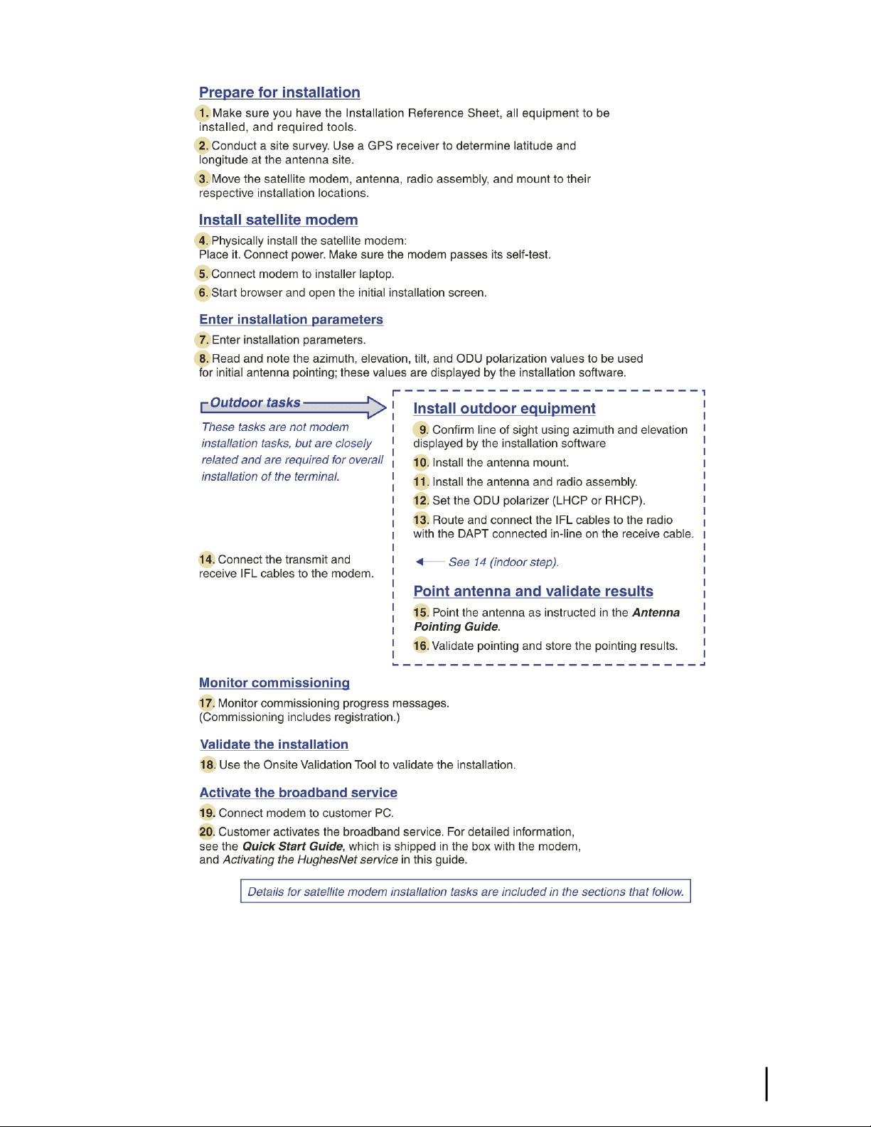
Installation summary
This installation guide covers installation of the satellite modem. It does not cover installation
of the other satellite terminal components: the antenna and radio assembly, antenna mount, and
IFL cables. However, to understand modem installation, you must understand the overall
installation process, which includes installation of all of the satellite terminal components. A
summary of the overall terminal installation process is presented in Figure 5: Satellite modem
installation summary on page 7. This diagram focuses on tasks performed by the installer to
install the satellite modem. Details for modem installation tasks are included in the sections that
follow.
Preparing for installationChapter 2
HN9000 Satellite Modem Installation Guide
6
1037576-0001 Revision E
Page 23
Chapter 2Preparing for installation
Figure 5: Satellite modem installation summary
Complete the steps in the order shown in Figure 5: Satellite modem installation summary on
page 7 unless you have a specic reason for doing them in a different order. In any case, make
sure all steps are completed. Be aware that the satellite modem has to provide the azimuth,
elevation, polarization, and tilt angle values before antenna pointing can be completed.
HN9000 Satellite Modem Installation Guide
1037576-0001 Revision E
7
Page 24

Installation checklist
Later in the installation process you are instructed to use the onsite validation tool (OVT) to
validate the installation. Validation ensures that the site is performing to acceptable standards.
To increase the likelihood that the site will pass validation the rst time you try, pay careful
attention to the items listed in the checklist below as you install the modem, antenna, and
IFL cables.
IFL cables
cable part number.
Connectors and connections
Preparing for installationChapter 2
Use only approved cables.
Do not exceed maximum length for the ODU type (such as 2 W or 4 W), cable type, and
Do not exceed the cable bend radius.
Properly terminate cables.
Use only connector types that are approved for the type of cable used. Check all connections
for tightness.
Outdoors:
Make sure F connectors connected to the radio assembly are tightened to 22 in-lb torque.
Carefully follow waterproong procedures, using dielectric grease and Hughes-approved
weatherproof tape.
Power source
Before connecting the modem power supply to the AC power source (using a surge protector),
use an AC outlet tester to verify that the power outlet is wired correctly. Wiring problems may
include:
• Hot and neutral wires reversed
• Neutral and ground wires reversed
• Open ground (incomplete connection)
• Open neutral
If the outlet is wired improperly, notify the customer that you are not permitted to connect the
system to a faulty outlet. Do not proceed with the installation until a properly wired outlet is
provided.
Grounding (modem, antenna, radio, and IFL)
Adhere to Hughes grounding requirements.
Use only approved ground wires, ground blocks, lugs, and clamps.
For detailed information refer to the appropriate FSB, as listed in Table 2: Related installation
documents on page 9.
HN9000 Satellite Modem Installation Guide
8
1037576-0001 Revision E
Page 25

Conducting a site survey
Survey the customer site to conrm that it is satisfactory for installation of the satellite terminal.
The tasks listed here are the key tasks related to installation of the satellite modem. For complete
site survey information, see the Antenna Site Preparation and Mount Installation Guide
(1035678-0001).
1.
Use a GPS receiver to determine the latitude and longitude at the antenna site. Note the
readings.
2.
Make sure there is an unobstructed line of sight to the satellite indicated on the Installation
Reference Sheet.
3.
Conrm that the customer’s computer meets the requirements listed in Computer requirements
on page 12.
Instructions for other terminal components
Chapter 2Preparing for installation
This installation guide covers only installation of the satellite modem. For installation instructions
for other components, see Table 2: Related installation documents on page 9. You can view
or download these documents on the HughesNet Installation Portal at
https://dwayinstalls.hns.com/start/loginInstaller.jsp. If you have any problem logging in,
contact Installer Support.
Table 2: Related installation documents
Safety (all components)
Site survey
Site preparation
Antenna mounts
IFL
IFL cables (specifications, approved
types, maximum lengths)
IFL cable connectors
Grounding
Ground blocks
Where to find instructionsComponent or topic
Antenna Site Preparation and Mount Installation Guide
(1035678-0001)
Field Service Bulletin (FSB), IFL Cable, Approved List (with
lengths) for Spaceway Domestic Installations (FSB_080202_01)
Field Service Bulletin (FSB), HNS Broadband Requirements for
RG-6 and RG-11 IFL Cable Connectors, Ground Blocks, and
Ground Block Location (FSB_050518_01)
Antenna
Radio assembly
Site validation (OVT)
See the antenna installation manual for the specific antenna model
you are installing.
Ka-Band Antenna Pointing Guide (1037663-0001)Antenna pointing
Installer’s Guide to the Ka-Band Onsite Validation Tool (OVT)
(1038091-0001)
HN9000 Satellite Modem Installation Guide
1037576-0001 Revision E
9
Page 26
Also see and adhere to the customer-specic installation specication. Typically these
specications apply to all installations for a particular company.
Power supply information
The power supply is included in the satellite modem shipping carton.
Figure 6: Power supply for the HN9000 satellite modem
Preparing for installationChapter 2
Before proceeding, make sure you have the correct power supply. Check the part number on the
power supply and refer to Table 3: Power supply specications for the HN9000 satellite modem
on page 10.
Table 3: Power supply specifications for the HN9000 satellite modem
Power suppl y type and
part number
AC/DC, 73 W
P/N 1501006-0001
• Always use the power supply provided with the satellite modem. The modem’s performance
may suffer if the wrong power supply is used.
• Connect the power supply to a three-wire, grounded outlet with an input of 110/130 VAC.
A suitable surge protector is recommended to protect the satellite modem from possible
damage due to power surges.
• If the satellite modem is installed outside the United States or Canada, observe the power
standards and requirements of the country where it is installed.
Power cordElectrical requirementsApplication
HN9000 satellite modem
with 1-W or 2-W radio
Input line voltage:
100 – 130 V, 2 A maximum
Input line frequency:
Detachable, for 110
VAC outlet type.
10
60 Hz AC
Rated power consumption: 73 W
HN9000 Satellite Modem Installation Guide
1037576-0001 Revision E
Page 27

If there is any reason to remove power from the satellite modem, always unplug the AC power
cord from the power source (power outlet, power strip, or surge protector). Do not remove the
DC power cord from the modem’s rear panel. Doing so could result in an electrical shock or
damage the modem.
When you re-apply power to the modem, plug the AC power cord into the power source.
Primary tools and equipment needed for installation
To install the satellite modem, you need the following items, which are included in the satellite
modem shipping carton:
• Satellite modem.
• Power supply.
• Ethernet cable.
To install the satellite modem, antenna assembly, and IFL cables you also need the additional
items listed below.
• Antenna.
• IFL cables, cable connectors, and ground blocks – You need enough cable to connect the
satellite modem to the antenna (transmit cable and receive cable). For additional information,
see Table 2: Related installation documents on page 9.
• Laptop computer (installer computer) with Internet Explorer browser installed.
• DAPT – A small device that guides the installer through the antenna pointing process and
displays pointing values.
• Squinter – A tool used to ne point the antenna by capturing the satellite signal from different
portions of the antenna reector surface. The squinter type depends on the radio assembly
to be installed, as explained in the Ka-Band Antenna Pointing Guide (1037663-0001).
• Fine azimuth pointing tool – Required for some antenna models.
• GPS receiver – The GPS receiver must give readings accurate to 1/1000 minute (for example,
60 degrees, 15.152 minutes).
• Installation Reference Sheet – This document describes the work to be done and provides
important information that needs to be entered on the installation screens—the Terminal
site name or ID and parameters that are required for installation.
Chapter 2Preparing for installation
No tools are required to install the modem. For tools needed to install the antenna mount and
antenna and point the antenna, see:
• Antenna Site Preparation and Mount Installation Guide (1035678-0001)
• Ka-Band Antenna Pointing Guide (1037663-0001)
• The installation manual for the antenna model you are installing
Additional equipment
This section discusses additional equipment that is recommended and equipment you may need
depending on the specic installation.
HN9000 Satellite Modem Installation Guide
1037576-0001 Revision E
11
Page 28

Use a surge protector
The customer is advised to provide a surge protector (recommended). If a surge protector is not
present, connect the modem power supply to a wall outlet or other power source.
A suitable surge protector is recommended to protect the satellite modem from possible damage
due to power surges.
Requirements for IFL cables, connectors, and ground blocks
You must use approved cable types and connectors to connect the modem to the outdoor satellite
antenna. For grounding, you must use approved ground blocks and grounding connectors. For
detailed specications and information on these components, see the documents listed in Table
2: Related installation documents on page 9.
A hub may be required
Preparing for installationChapter 2
If the satellite modem is to be connected to a network, an Ethernet hub or other similar device
is required. The customer must supply and congure the hub or other device, including required
cables, according to the documentation for the hub or other network device.
Computer requirements
Make sure the laptop computer you use to install the satellite modem and the customer’s computer
that will be connected to the modem meet the following minimum requirements. Requirements
are listed by operating system.
All requirements are minimum requirements except those identied as recommended.
The satellite modem may work with a computer that does not meet these requirements, but
Hughes supports only computers that meet these requirements.
Microsoft Windows Vista Home Basic
• Processor speed: 800 MHz
• System memory: 512 MB
• Free hard disk space: 150 MB
Microsoft Windows Vista Home Premium, Business, Enterprise, or Ultimate
• Processor speed: 1 GHz
• System memory: 1 GB
• Free hard disk space: 150 MB
12
Microsoft Windows XP, Professional or Home Edition
•
Processor speed: 233 MHz. Recommended: 300 MHz or higher
•
System memory: 128 MB. Recommended: 256 MB or more
• Free hard disk space: 150 MB
Microsoft Windows 2000, Professional Edition with Service Pack 4
HN9000 Satellite Modem Installation Guide
1037576-0001 Revision E
Page 29

• Processor speed: 133 MHz
• System memory: 128 MB
• Free hard disk space: 150 MB
Apple Mac 9.0-10.5 (excludes 10.0)
• Processor speed: 300 MHz
• System memory: 128 MB
• Free hard disk space: 150 MB
Note: The satellite modem can be used with a Mac computer that meets these requirements,
but Mac computers are not supported as a tool for installing the satellite modem.
Networking requirements
• Ethernet port
• Ethernet cable (provided)
• Ethernet NIC, 10/100 Mbps, congured as follows:
• Auto-negotiate
• DHCP enabled
• Obtain an IP address automatically
Note: The computer can be congured to use a public IP address if the HughesNet
service plan provides for one or more public IP addresses.
Chapter 2Preparing for installation
Internet browser
• Internet Explorer 6 or greater, Netscape Navigator, Mozilla Firefox, Safari (for Windows
and Mac)
• Browser settings:
• HTTP 1.1 or greater enabled
• Proxy settings disabled
Configuring the installer laptop IP address
You have several options for conguring the IP address on your installer laptop computer, as
explained below.
The option you choose affects your ability to perform various installation tasks. To enter
installation parameters and subsequently monitor commissioning progress, including state codes,
which indicate installation progress, the laptop must be congured for link-local IP address
169.254.10.10. However, you cannot browse the Internet if the laptop is congured to use this
address. After commissioning, you must use the address 192.168.0.1 with DHCP enabled to
open the System Control Center.
From the following options, choose the address conguration that best suits your preferences
and the way you work.
• Link-local IP address with alternate private IP address – If you want to congure the
link-local IP address 169.254.10.10 on the installer laptop, but you do not want to remove
that address each time you go to the System Control Center, you can congure an alternate
private IP address, 192.168.0.2, along with the 169.254.10.10 address. For instructions see
Conguring a link-local IP address on the installer laptop on page 14 and Conguring an
alternate IP address on the installer laptop on page 15.
HN9000 Satellite Modem Installation Guide
1037576-0001 Revision E
13
Page 30

Preparing for installationChapter 2
• DHCP enabled – If you enable DHCP on the laptop (no static IP address) you can type
192.168.0.1 or www.systemcontrolcenter.com in the browser address bar anytime after
commissioning to go to the System Control Center home page. DHCP allows your laptop
to obtain IP addresses automatically. This option may be more convenient if you use your
laptop for a variety of activities.
However, if DHCP is enabled on the laptop during commissioning, you must periodically
press the F5 function key or increase the screen refresh rate to see if a commissioning error
has occurred or to know when commissioning has completed. Also, with DHCP enabled,
you cannot observe the entire registration process (part of commissioning) as it occurs. This
is because when the modem is updating and rebooting, you cannot launch the screen that
shows the registration progress.
For instructions see Conguring a computer to use DHCP on page 109.
Note: If you switch from using the link-local IP address to DHCP enabled, the modem
may acquire the dynamic address more quickly if you force a new connection (on a
Windows computer) as follows:
1.
Open a (DOS) Command Prompt window.
2.
Type ipconfig/release.
3.
Press Enter.
4.
Type ipconfig/renew.
5.
Press Enter.
• Link-local IP address (only) – If you congure link-local address 169.254.10.10 on the
installer laptop, you will not be able to open the System Control Center by entering
192.168.0.1 or www.systemcontrolcenter.com in the browser address bar. The congured
link-local IP address will not allow access to the typed-in address. A typed address will only
work if you clear the link-local IP address from the laptop IP conguration and enable
DHCP, or congure an additional static private IP address as explained in Conguring an
alternate IP address on the installer laptop on page 15.
Configuring a link-local IP address on the installer laptop
These instructions explain how to congure the installer laptop computer to use the link-local
IP address 169.254.10.10. If you also want to congure an alternate address on the installer
laptop (optional, for convenience), see Conguring an alternate IP address on the installer
laptop on page 15.
These instructions are for Windows XP. Procedures for other Windows operating systems are
similar. If you need additional instructions, see Conguring a computer for a public IP address
on page 117.
1.
Use the Windows Control Panel on the installer laptop to open the Local Area Connection
Properties dialog and then the Internet Protocol (TCP/IP) Properties dialog. If you need more
specic instructions, see Conguring a computer for a public IP address on page 117.
14
HN9000 Satellite Modem Installation Guide
1037576-0001 Revision E
Page 31

Chapter 2Preparing for installation
Figure 7: Internet Protocol Properties dialog
2.
In the Internet Protocol Properties dialog, click Use the following IP address.
3.
Enter the following:
a)
In the IP address eld, type 169.254.10.10.
This will be the laptop IP address.
b)
Typically the Subnet mask eld auto-populates to 255.255.0.0. If it does not, enter this
value manually.
c)
In the Default gateway eld, type 169.254.0.1.
This is the address you will use to access the modem’s installation screens.
d)
In the Preferred DNS server eld, type 66.82.4.8.
e) Click OK twice to close the Internet Protocol Properties dialog and the Network
Connections dialog.
The laptop computer is now congured to communicate with the satellite modem so you can
enter installation parameters and monitor commissioning progress.
Configuring an alternate IP address on the installer laptop
If you do not want to make address changes on the laptop computer during modem installation,
you can congure a link-local IP address and a second (alternate) private IP address. Then you
can access the satellite modem and browse the Internet without changing the IP address settings
on the laptop. The instructions here assume you have already set up an address on the laptop
as explained in Conguring a link-local IP address on the installer laptop on page 14.
Congure the second (alternate) IP address as follows:
1.
Use the Windows Control Panel to open the Local Area Connection Properties dialog and
then the Internet Protocol (TCP/IP) Properties dialog.
2.
Click Advanced to open the Advanced TCP/IP Settings dialog.
3.
In the IP addresses box, click Add to open the TCP/IP Address dialog.
HN9000 Satellite Modem Installation Guide
1037576-0001 Revision E
15
Page 32

Preparing for installationChapter 2
a)
Type the second IP address 192.168.0.2.
b)
Type the subnet mask 255.255.255.0.
c) Click Add.
4.
In the Default gateways box, click Add to open the TCP/IP Gateway Address dialog.
a)
Type the second gateway IP address 192.168.0.1.
b) Click Add.
5.
Click OK three times to close the Advanced TCP/IP settings dialog, Internet Protocol
Properties (TCP/IP) dialog and the Network Connections dialog.
6.
Close the Network Connections and Control Panel windows.
For your reference, Figure 8: Settings for link-local and alternate addresses on the laptop on
page 16 shows the information you should see in the Internet Protocol Properties dialog and
Advanced TCP/IP Settings dialog after you have set up the primary address and an alternate
address on the installer laptop. In the Advanced TCP/IP Settings dialog, the laptop addresses
are listed under IP Addresses (primary rst, then alternate), and the modem addresses are listed
under Default gateways.
16
Figure 8: Settings for link-local and alternate addresses on the laptop
HN9000 Satellite Modem Installation Guide
1037576-0001 Revision E
Page 33

Chapter
3
Installing the satellite modem
Topics:
• Selecting the modem location
• Modem operating position
• Powering up the modem
• Connecting the installer laptop to
the modem
• Entering the installation
parameters
Installation of the HN9000 satellite modem consists of physical installation,
which is very simple, followed by a complex but highly automated process that
fully prepares the modem for operation on the satellite network. Installation
tasks include:
• Physical installation and power-up
• Entering required installation parameters
• Pointing the antenna
• Monitoring the commissioning process
• Service activation
Typically, the satellite modem is installed as part of a new satellite terminal
installation. Under some circumstances, a modem may have to be re-installed.
Note: In some cases re-installation may correct a specic service problem.
Re-installation should only be done by a qualied installer or service
technician or someone under specic direction by Hughes Customer Care.
The installation software is factory pre-installed in the satellite modem. If
necessary, this software is automatically updated as part of the installation
process. You access the installation software through a browser on your installer
computer to perform tasks such as entering required installation parameters.
HN9000 Satellite Modem Installation Guide
1037576-0001 Revision E
17
Page 34

Selecting the modem location
Select a location for the satellite modem that will accommodate all required cable connections,
including the power source. Place the modem in the desired location.
• Do not block any ventilation openings. Do not place the satellite modem near heat sources
such direct sunlight, radiators, heat registers or vents, ovens, stoves, or other apparatus
(including ampliers) that produce heat.
• Leave 6 inches of space around the top and sides of the modem to ensure ventilation and
prevent overheating.
Modem operating position
Installing the satellite modemChapter 3
Install and operate the HN9000 modem only in a vertical position, that is, resting on its built-in
base as shown in Figure 9: HN9000 in vertical position on page 18. In any other position, the
modem may overheat and malfunction because of inadequate ventilation.
Figure 9: HN9000 in vertical position
To avoid overheating, install and operate the HN9000 modem only in the upright vertical position
as shown in Figure 9: HN9000 in vertical position on page 18.
Powering up the modem
For this task you must have the satellite modem and the correct power supply. To make sure
you have the correct power supply, see Power supply information on page 10.
18
HN9000 Satellite Modem Installation Guide
1037576-0001 Revision E
Page 35

Chapter 3Installing the satellite modem
Test the power outlet and power up the satellite modem:
1.
Use an AC outlet tester to verify that the power outlet is wired correctly.
Wiring problems may include:
• Hot and neutral wires reversed
• Neutral and ground wires reversed
• Open ground (incomplete connection)
• Open neutral
If the outlet is wired improperly, notify the customer that you are not permitted to connect
the system to a faulty outlet. Do not proceed with the installation until a properly wired outlet
is provided.
2.
Connect the DC power cord to the modem’s DC IN connector, as shown in Figure 10:
Powering up the modem on page 19.
3.
Connect the AC power cord to the three-prong connector on the modem’s power supply.
4.
Connect the surge connector (recommended) to an AC power outlet.
5.
Apply power by connecting the AC power cord to the surge connector.
The Power LED turns on, and various LEDs turn on and off as the modem performs a self-test
and transitions to boot phase. (Indication that the self-test passed appears later as Self Test
: Passed on the screen shown in Figure 22: Terminal Initialization Sequence complete on
page 34.)
Figure 10: Powering up the modem
A suitable surge protector is recommended to protect the satellite modem from possible
damage due to power surges.
Connecting the installer laptop to the modem
For this task you need the provided Ethernet cable.
To access the satellite modem so you can perform the required installation procedures, you
connect your installer laptop computer to the modem. After the modem is installed and registered
HN9000 Satellite Modem Installation Guide
1037576-0001 Revision E
19
Page 36

Installing the satellite modemChapter 3
with the satellite network, you connect the modem to the customer’s computer. During modem
installation the installer laptop computer must be directly connected to the modem without any
intervening connection.
Connect the installer laptop to the modem:
1.
Use the Ethernet cable to connect your laptop computer directly to the modem's LAN port,
as shown in Figure 11: Connecting the installer’s laptop computer to the modem on page
20.
Do not connect the installer laptop to the modem through an Ethernet router or switch.
Figure 11: Connecting the installer’s laptop computer to the modem
2.
Make sure the satellite modem is not connected to the customer’s computer.
3.
If you are running rewall software on the laptop computer, disable it until you complete
installation of the modem.
The LAN LED on the front of the modem should now be on.
Entering the installation parameters
Prerequisites:
•
Before proceeding, make sure the link-local IP address 169.254.0.1is set up on the installer
laptop computer as explained in Setting the installer laptop IP address.
• For this task you need the Installation Reference Sheet, which lists parameters you need to
enter on screens displayed by the modem’s installation software.
Installation of the satellite modem is accomplished through actions performed by the installer,
network and installation software, and interaction between the satellite modem and the NOCC.
After powering up the modem, the installer enters required parameters. Then, before installation
can continue, the installer must accurately point the antenna.
Enter information about the site, satellite, antenna, and radio, as explained in this section. Enter
the values shown on the Installation Reference Sheet. Be sure to enter the information correctly
or you may not be able to successfully install the modem.
20
1.
Start a web browser on your laptop computer.
HN9000 Satellite Modem Installation Guide
1037576-0001 Revision E
Page 37

2.
Type 169.254.0.1 in the browser address bar and press Enter.
The System Control Center home page opens.
Note: Use 169.254.0.1 to open the System Control Center only before the satellite
modem is commissioned. After the modem is commissioned, use the address
www.systemcontrolcenter .comor 192.168.0.1. To use 192.168.0.1, the installer’s
laptop must be congured for two addresses as described in Conguring an alternate
IP address on the installer laptop on page 15, and DHCP must be enabled.
Chapter 3Installing the satellite modem
Figure 12: System Control Center home page
The System Status and System Info buttons are always visible near the top of the System
Control Center screens. Three additional buttons are visible after the modem has been
commissioned and is operational.
3.
Click the small icon indicated by the arrow in Figure 13: Icon for opening Advanced Pages
on page 21.
Figure 13: Icon for opening Advanced Pages
HN9000 Satellite Modem Installation Guide
1037576-0001 Revision E
21
Page 38

Installing the satellite modemChapter 3
The browser opens the Installation Parameters screen, which appears within a larger screen
titled Advanced Conguration and Statistics (Figure 14: Installation Parameters screen on
page 22). The Installation Parameters screen is the rst of several screens that appear within
the Advanced Conguration and Statistics screen as you install the modem.
Figure 14: Installation Parameters screen on page 22 is an example, showing the Installation
Parameters screen with parameters entered. You must enter the specic parameters for the
site where you are installing the satellite modem, as listed on the Installation Reference Sheet.
Do not copy parameters from this example.
22
Figure 14: Installation Parameters screen
Note: On some screens and in some messages you may see the word terminal. This
word refers to the satellite modem.
4.
For each of the following parameters, select the value that is listed on the Installation
Reference Sheet:
• Terminal site name – Note that this eld is case-sensitive.
• A code – Satellite orbital location. The value 0949505, which corresponds to the orbital
location 94.950° W.
• B code – Antenna size. The B code and C code values are used to ensure that the satellite
modem transmits at the correct maximum power.
•
HN9000 Satellite Modem Installation Guide
1037576-0001 Revision E
Antenna sizeB code
0.74 m0749
0.98 m0988
1.2 m1208
Page 39

Antenna sizeB code
1.8 m1804
For the HN9000 modem, select 0.74 m or 0.98 m antenna size only.
• C code – ODU power
Nominal ODU powerC code
1 W000103
2 W000200
4 W000406
Chapter 3Installing the satellite modem
001004
For the HN9000 modem, select 1 W or 2 W ODU power only.
• U code – Select the U Code (Satellite ID) shown on the Installation Reference Sheet.
The A, B, C, and U code elds each have a drop-down menu for easier and more accurate
data entry. Make your selections from these menus. You can type your own value in the
space that reads, Enter Your Own Value—but do this only if you are specically instructed
to do so by Hughes Installer Support.
Note: You can clear previously entered installation information by clicking Control
in the screen’s left panel, and then clicking Clear Terminal Install. A message warns
that this operation could make the modem inoperable. Execute this command only
if you are condent you know what to expect. The modem reboots, and all elds are
cleared.
5.
Enter the site latitude and longitude values from your GPS receiver, in degrees and minutes
to three decimal places.
Figure 15: Fields where latitude and longitude are entered
10 W
Power booster unit
The modem’s installation software uses the site latitude and longitude to determine the uplink
and downlink cells to which the modem will be assigned and the uplink polarization setting
on the radio assembly (LHCP or RHCP).
You must enter the latitude and longitude in the format shown in Figure 15: Fields where
latitude and longitude are entered on page 23:
• Latitude: DD MM.MMM
• Longitude: DDD MM.MMM
Enter degrees in whole numbers only, with no decimals. Degrees latitude is 1 or 2 digits (0
– 90° north or south). Degrees longitude is 1 – 3 digits (0 – 180° east or west). Examples of
degrees correctly entered:
5, 05, 42 or 112
Enter minutes as a whole number plus a decimal fraction to three places (thousandths) with
no seconds. Examples of minutes correctly entered:
HN9000 Satellite Modem Installation Guide
1037576-0001 Revision E
23
Page 40

Installing the satellite modemChapter 3
7.223 and 34.775
If you type a number with a leading zero, the zero is not displayed after you press Submit
Installation Parameters. For example, if you type 06 it is displayed as 6.
If you enter the site latitude and longitude incorrectly, the modem will report a Probing
Failureand will not be able to uplink to the satellite. Probing refers to the rst time the
modem tries to transmit back to the satellite.
Some GPS receivers are suitable for Ka-band installations such as HN9000; some are not
suitable. For a complete discussion on various GPS receivers, see Field Service Bulletin
(FSB), Introduction to Commercial GPS Units for Ka Installers (FSB_080404_01).
Figure 16: Example of a GPS receiver display on page 24 shows an example of a GPS
receiver display showing latitude and longitude along with the elds on the Installation
Parameters screen where these values are entered.
Figure 16: Example of a GPS receiver display
For Latitude, the North radio button is selected by default. For Longitude, West is selected
by default.
Figure 17: State code displayed below latitude and longitude elds on page 24 shows state
code 7 displayed beneath the latitude and longitude elds.
Figure 17: State code displayed below latitude and longitude fields
The current state code is displayed on several of the installation screens and on some System
Control Center screens. The state code indicates the current operational state of the satellite
modem.
While you are entering installation parameters but before you click Submit Installation
Parameters, it is normal to see state code 4, 5, 7, or 8. To see a list of state codes with
explanation, click the state code. For additional information, see Table 17: State codes on
page 88.
Note: Do not change the Antenna Pointing Indicator Delay value.
24
HN9000 Satellite Modem Installation Guide
1037576-0001 Revision E
Page 41

Chapter 3Installing the satellite modem
6.
Click Submit Installation Parameters.
The modem saves the information you entered to ash memory. If you enter a new parameter
or modify a parameter, the modem reboots. After the reboot, the Terminal Pointing Info
screen appears. See Figure 18: Terminal Pointing Info screen on page 25.
Figure 18:Terminal Pointing Info screen
If you want to change any of the values you previously entered on the Installation Parameters
screen, click Modify Installation Parameters. This returns you to the Installation Parameters
screen.
Do not click the Abort Pointing button. This would skip the pointing phase and subsequently
cause registration to fail. Then you could only register the modem by obtaining a pointing
override from the NOCC. The Abort Pointing button is used only during manual IDU
(modem) replacement, for which the NOCC explicitly approves an antenna pointing override
for the site.
Note: At this point, prior to antenna pointing, the SQF value may be 0, indicating that
the demodulator is initializing, or 1, indicating that the demodulator is searching for a
beacon signal. Most of the time the SQF value is 1 until the demodulator acquires the
beacon signal; then it is > 1.
7.
Make a note of the values shown in the Computed Parameters area of the Terminal Pointing
Info screen:
• Azimuth
• Elevation
• Tilt angle
• ODU polarization setting (LHCP or RHCP)
You will need the azimuth and elevation values to point the antenna.
HN9000 Satellite Modem Installation Guide
1037576-0001 Revision E
25
Page 42

Installing the satellite modemChapter 3
Note: When you install the antenna, be sure to set LHCP or RHCP as indicated on the
Terminal Pointing Info screen (Setting for ODU Polarization). If you set polarization
incorrectly—for example, LHCP when RHCP is specied—the satellite modem will
not receive a signal.
For explanation of the information in the Terminal Info section (lower part) of the Terminal
Pointing Info screen, see Table 6: Parameters in Terminal Info section (appears on two
installation screens) on page 38.
26
HN9000 Satellite Modem Installation Guide
1037576-0001 Revision E
Page 43

Chapter
4
Installing outdoor equipment and antenna pointing
Topics:
• Installing the IFL cables
• Pointing the antenna
After you enter the installation parameters on the Installation Parameters screen
and click Submit Installation Parameters, the satellite modem enters pointing
mode. This allows you to point the antenna.
This section provides some general information about antenna installation and
pointing, especially as these tasks relate to modem installation. For complete
instructions on installing antenna mounts, antennas (including radio assemblies)
and pointing, refer to the manuals listed in Instructions for other terminal
components on page 9.
The HN9000 satellite modem can be used with a .74 m or .98 m two-way satellite
antenna. Assemble and install the antenna assembly according to the antenna
installation manual. If you do not have the antenna installation manual, nd the
required antenna type and model on the Installation Reference Sheet. Then nd
the installation manual for the specied antenna on your installation support
web site. The antenna and satellite modem are shipped in separate boxes.
When you install the antenna assembly, read and follow all safety alerts and
instructions in the antenna installation manual and in the Antenna Site
Preparation and Mount Installation Guide (1035678-0001).
HN9000 Satellite Modem Installation Guide
1037576-0001 Revision E
27
Page 44

Chapter 4
Installing the IFL cables
Before you can point the antenna, you must route the IFL cables between the indoor satellite
modem location and the antenna. Then you connect the modem and the antenna by connecting
the IFL cable to both components.
(See also Requirements for IFL cables, connectors, and ground blocks on page 12.)
Routing and connecting the IFL cables
To point the antenna, you must connect the modem to the antenna and install the DAPT (a
Hughes tool that displays antenna pointing values.)
1.
Route the IFL cables from the indoor satellite modem location to the antenna.
The routing path depends on the building conguration. Guidelines for installing IFL cables
are included in the Antenna Site Preparation and Mount Installation Guide (1035678-0001).
2.
Connect the transmit IFL cable to the transmit connector on the radio transmitter.
(The transmit cable is not shown in Figure 19: In-line connection of the DAPT on page 28.)
3.
Connect the receive IFL cable to the DAPT, as shown in Figure 19: In-line connection of
the DAPT on page 28.
Installing outdoor equipment and antenna
pointing
28
Figure 19: In-line connection of the DAPT
For additional information on pointing and the DAPT, see the Ka-Band Antenna Pointing
Guide (1037663-0001).
4.
Use a temporary cable to connect the DAPT to the LNB on the radio assembly as shown in
Figure 19: In-line connection of the DAPT on page 28.
This is a temporary arrangement that is required for antenna pointing.
Note: The connectors on the DAPT are labeled IDU and LNB. If the cable from the
satellite modem (the IDU) and the cable from the radio assembly on the antenna are
connected to the wrong connectors, the DAPT will not receive a signal.
IFL grounding requirement
The coaxial IFL cables and the ground block to which they are connected must meet the grounding
requirements specied in the following warning:
HN9000 Satellite Modem Installation Guide
1037576-0001 Revision E
Page 45

pointing
You must comply with applicable local codes and the grounding requirements in Field Service
Bulletin (FSB), HNS Broadband Requirements for RG-6 and RG-11 IFL Cable Connectors,
Ground Blocks, and Ground Block Location (FSB_050518_01). Improper grounding can result
in electric shock injury and/or property damage.
Labeling the IFL cables
Label the receive and transmit IFL cables at the outdoor point-of-entry and at the indoor location
where the satellite modem is installed as follows:
•
Wrap a piece of red electrical tape around the receive cable, and mark SAT IN on the tape.
•
Wrap a piece of blue electrical tape around the transmit cable, and mark SAT OUT on the
tape.
Connecting the IFL cables to the modem
Connect the transmit and receive IFL cables to the satellite modem.
Chapter 4Installing outdoor equipment and antenna
1.
Connect the transmit and receive cables to the connectors on the rear panel of the modem as
shown in Figure 20: Connecting the transmit and receive cables on page 29.
Figure 20: Connecting the transmit and receive cables
The transmit and receive cable connectors must be securely tightened.
• Make sure each connector is properly aligned (not cross-threaded).
• The connector should be nger tight with no play.
Note: The satellite modem may operate correctly when rst installed even if the transmit
and receive cable connectors are not adequately tightened. However, problems could
HN9000 Satellite Modem Installation Guide
1037576-0001 Revision E
29
Page 46

Chapter 4
2.
Pointing the antenna
Make sure you have the DAPT and the correct squinter for the radio assembly to be installed.
You will need these tools to point the antenna.
1.
2.
Installing outdoor equipment and antenna
pointing
develop later. Therefore, successful modem operation is not an indication that the cables
are adequately tightened.
Make sure neither the satellite modem nor the customer’s computer are connected to an
Ethernet device.
Note: Do not connect any device to the satellite modem at this time except the installer
laptop computer. Ethernet devices may only be connected to the modem after it is
installed and commissioned.
Go outside to the antenna location.
Follow the procedure explained in the Ka-Band Antenna Pointing Guide (1037663-0001)
to point the antenna using the DAPT and squinter.
When you nish the pointing procedure, a screen message on the DAPT asks if you want to
store the pointing information in the satellite modem. If you answer yes, the modem exits
pointing mode. When the modem nishes downloading the pointing information, the DAPT
displays a Pointing Donemessage.
3.
Make sure you see the Pointing Donemessage on the DAPT.
Do not remove the DAPT until you see the Pointing Donemessage.
4.
Remove the DAPT and connect the receive IFL cable from the satellite modem to the LNB
on the radio assembly.
At this point the modem automatically begins the process of commissioning—which includes
registering with the NOCC, downloading operational software, and related activities.
5.
Go back inside to complete installation of the modem.
30
HN9000 Satellite Modem Installation Guide
1037576-0001 Revision E
Page 47

Chapter
5
Commissioning the satellite modem
Topics:
• Prerequisites for commissioning
• Monitoring the commissioning
process
• Troubleshooting installation
problems
During the commissioning phase of installation the satellite modem downloads
software and completes other activities so it can become an operational element
of the network. When commissioning is completed, the modem is ready for
service activation.
The NOCC and the modem communicate to make sure commissioning software
is loaded in the modem. If necessary, commissioning software is downloaded
to the modem. The commissioning software is only sufcient to complete
commissioning steps; it does not support end-user data transfer capabilities.
The modem interacts with the satellite to establish transmit timing and
synchronization. It interacts with the NOCC for authentication and registration;
and to obtain required software, security keys, and a preliminary conguration.
The NOCC noties the NSP that the satellite modem has registered with the
network.
The modem downloads a temporary conguration from the NOCC. The
temporary conguration allows the modem to communicate with the NSP so
the broadband service can be activated. Final conguration is provided to the
modem after service activation.
HN9000 Satellite Modem Installation Guide
1037576-0001 Revision E
31
Page 48

Prerequisites for commissioning
The following are prerequisites for commissioning:
• The satellite modem must be physically installed.
• The antenna must be pointed, and the modem must have exited pointing mode.
• Service for the modem must be congured by the service provider and the NOCC, and the
terminal site name previously entered by the installer (Figure 14: Installation Parameters
screen on page 22) must match the terminal site name congured by the service provider
and NOCC.
• The satellite modem must be dened at the NOCC and authorized for commissioning by
the service provider.
Monitoring the commissioning process
Commissioning activities are performed automatically by the satellite modem, the satellite, and
the NOCC. Commissioning begins when the modem exits pointing mode and progresses until
the modem reboots into normal operational mode. Normally, there is no need for intervention.
Commissioning the satellite modemChapter 5
After you point the antenna and respond Yes on the DAPT to store the pointing information, the
modem exits pointing mode and displays the Terminal Initialization Sequence screen on your
browser (Figure 21: Terminal Initialization Sequence in progress on page 33).
The Terminal Initialization Sequence screen lists each commissioning activity and each activity’s
progress as the satellite modem proceeds through the commissioning (or initialization) sequence.
Figure 21: Terminal Initialization Sequence in progress on page 33 shows the commissioning
process at a point when several commissioning activities have completed, but commissioning
is still underway. The activities occur in the order they are listed on the screen, top to bottom,
beginning with the self test.
32
HN9000 Satellite Modem Installation Guide
1037576-0001 Revision E
Page 49

Chapter 5Commissioning the satellite modem
Figure 21:Terminal Initialization Sequence in progress
An activity in progress is indicated by three dots after the name of the activity, for example:
Acquiring Keys...
Note: Downloading the commissioning software, if required, takes approximately 5 minutes.
Do not remove power during this download because you think it's taking too long. If you
do, you will have to wait until the commissioning software is broadcast again from the
NOCC plus the download time. The wait for the software broadcast your modem needs
can be as long as 20 to 25 minutes.
Downloading operational software takes about 10 to 20 minutes. This download occurs
after the commissioning software download, as shown in Figure 22: Terminal Initialization
Sequence complete on page 34.
During the initialization sequence, numerous procedures are performed that are critical for
operation of the satellite modem. In addition to the procedures listed on the Terminal Initialization
Sequence screen, the satellite modem probes to optimize its timing and power levels. Registration
refers to equipment identication, authentication, and registration with the satellite network.
During conguration reconciliation, the modem makes sure it has the correct conguration. The
modem also loads numerous proles that are required for network operation.
Monitor the commissioning process by viewing the Terminal Initialization Sequence screen.
Unless there is a problem (as indicated by an error message), you should not have to take any
action during this sequence except to monitor the process.
Monitor the initialization sequence screen while the modem progresses through the commissioning
process:
1.
Monitor the commissioning progress messages on the Terminal Initialization Sequence
screen.
When commissioning is complete, the Terminal Initialization Sequence screen shows
Installation Complete as the last progress message. This message is indicated by the arrow
in Figure 22: Terminal Initialization Sequence complete on page 34.
HN9000 Satellite Modem Installation Guide
1037576-0001 Revision E
33
Page 50

Commissioning the satellite modemChapter 5
Note: Some error messages are temporary. For example, you may see a message that
says a commissioning activity is halted; then in a short time the activity resumes.
Figure 22:Terminal Initialization Sequence complete
2.
In the event that an error condition prevents the commissioning process from completing,
refer to Table 7: Guidelines for installation troubleshooting on page 40 for troubleshooting
steps you can take.
Successful commissioning ends with the modem rebooting into normal operational mode.
For detailed information about the commissioning process, the Terminal Initialization Sequence
screen, and possible error messages, see Commissioning and installation reference information
on page 35. There is also a section on installation troubleshooting (Troubleshooting installation
problems on page 40). Unless you encounter a problem, you should not need this reference or
troubleshooting information, and you can proceed to Activating the HughesNet service on page
51.
Implementation of second IP address
After commissioning has completed, the installer should continue to use the address settings
specied in Setting the installer laptop IP address and should continue to use the 169.254.0.1
address to access the modem from the installer laptop. However, after the modem is activated
(a subsequent step), the installer cannot use this address to browse the Internet.
After commissioning, using the customer’s browser, you (or the customer) can type
www.systemcontrolcenter.com (or 192.168.0.1) to open the System Control Center. To use
192.168.0.1, DHCP must be enabled on the computer.
34
Note: You cannot use the address 169.254.0.1 to access the modem from a computer that
has DHCP enabled.
HN9000 Satellite Modem Installation Guide
1037576-0001 Revision E
Page 51

Commissioning and installation reference information
This reference section:
• Lists the commissioning activities and corresponding progress messages that are displayed
on the Terminal Initialization Sequence screen.
• Includes explanation of error messages you could see in the event of a problem.
• Explains the elds in the Terminal Info section, which appears on the Terminal Pointing
Info screen and on the Terminal Initialization Sequence screen.
For explanation of state codes, which appear on the installation screens (and System Control
Center screens) as State code plus a number, see Table 17: State codes on page 88.
Commissioning activities and progress messages
All possible progress (or status) messages for each commissioning activity are shown in Table
4: Commissioning progress messages on page 35. If a status message indicates a problem, refer
to Table 7: Guidelines for installation troubleshooting on page 40.
Table 4: Commissioning progress messages
Chapter 5Commissioning the satellite modem
Phase (activity)
Self Test
Satellite Downlink
Signal
Commissioning
Software
indicating normal progress
Passed
Acquiring
Acquired
Waiting for System
Information
Downloading beginning...
Download Completed
Please wait for ne xt broadcast
of Software in {number}
mins...
Possible error messagesProgress messages
Attempting to acquire downlink signal in microcell
{number}, retry # {number}
Downlink signal acquisition failed, retry # {number}
Final cell selection failed. (This message could mean
you are trying to install the modem in a location that
is outside the network service area.Corrective action:
Make sure you entered the correct latitude and
longitude on the Installation Parameters screen.)
Satellite Uplink
Signal
Acquiring Signal
Acquired
Uplink signal acquisition failed (Ack attempt #
{number})...
Attempting Probing (attempt # {number}) ...
Probing failed (attempt # {number})...
Probing Failed: Downlink Signal Lost
Corrective actions:
Make sure the transmit cable is connected. (Pointing
completion verifies the receive cable connection.)
HN9000 Satellite Modem Installation Guide
1037576-0001 Revision E
35
Page 52

Commissioning the satellite modemChapter 5
Phase (activity)
Receive Satellite
Information
Registration Process
Access Keys
Synchronization
Configuration and
Operational Software
Possible error messagesProgress messages
indicating normal progress
b) The Lat/Long values entered in the Installation
Parameters screen are not correct f or the site. Probing
is quite sensitive to the accuracy of these values,
whereas pointing is not as sensitive.
Receiving Data
Complete
Registering (attempt # {number})...Registering
Unable to register...Registered
Registration Failed ...
For details concerning Registration messages, see
Registration error messages on page 36.
Acquiring Keys
Synchronized
Downloading
Software Download Complete
Downloaded
Configuration
Reconciliation
Normal Mode
Messages in bold text in the second column indicate completion of the activity.
Registration error messages
In Progress
Complete
Installation Complete.
Fields in the Terminal Info part of the Terminal Initialization Sequence screen are explained in
Terminal Info parameters on page 38.
Modem registration refers to registration with the satellite network. Even after registration, the
modem cannot connect to the Internet until it is activated.
Reasons for possible registration error messages are listed in Table 5: Reasons for registration
errors and corrective actions on page 36. This table includes only the most common registration
error messages; it does not include all possible registration error messages.
Note: If you see Registration Failed...with no additional error information, the modem
will try to register again after a short time.
Table 5: Reasons for registration errors and corrective actions
36
Corrective actionReasonError message
Last Fail Reasons (reason for the last registration failure)
HN9000 Satellite Modem Installation Guide
1037576-0001 Revision E
Page 53

Chapter 5Commissioning the satellite modem
Corrective actionReasonError message
Antenna Pointing
Validation Failure
ODU Radio Power
Mismatch
Registration Not
Authorized
Relocation Not
Authorized
SAM ESN Blacklisted
by Operator
ST ESN Already In
Use
ST Replacement Not
Authorized
Antenna is not properly pointed or the
pointing process has been aborted.
The C code (ODU power) selected on the
Installation Parameters screen does not
match the wattage of the installed radio.
Operator has explicitly disabled
registration capability for this satellite
modem.
Attempting to register previously
registered ST Site Name or ST Site ID
using latitude and longitude values outside
of assigned microcell.
The satellite modem’s security access
module is barred for a reason such as
nonpayment for service.
Attempting to register a previously
registered ST Site Name or ST Site ID at
a different location.
Attempting to register different equipment
using a previously registered ST Site
Name or ST Site ID.
Repoint the antenna and ensure that
Azimuth and Elevation validations pass
as indicated in the DAPT during pointing.
Check the radio and check the Installation
Parameters screen to make sure the
correct C code is specified.
Call Installer Support with site name to
resolve the issue.
Call Installer Support with site name to
resolve the issue.
Call Installer Support with the satellite
modem’s ESN and ST Name to resolve
the issue.
Call Installer Support with the satellite
modem’s ESN to resolve the issue.
Call Installer Support with site name to
resolve the issue.
Invalid Site Name.
Please verify name
and try again.
Group Barred
Individually Barred
Registration Services
Disabled
The ST Site Name sent by the satellite
modem is not known at the NOCC.
Management reasons for registration failure
The satellite modem is included in a group
of modems that are barred from service.
The satellite modem is barred from
service.
Registration services are not available
because internal maintenance is
underway.
Satellite receive link is down.Rx Air Interface Down
Satellite transmit link is down.Tx Air Interface Down
Check to make sure the Terminal Site
Name is the correct name and was
entered correctly.
Call Installer Support with site name to
resolve the issue.
Call Installer Support with site name to
resolve the issue.
No action is required. Registr ation service
will be enabled when maintenance is
complete.
Verify the installation, for example, check
cable connections and connectivity to the
antenna. If the problem is not corrected,
repoint the antenna.
Verify the installation, for example, check
cable connections and connectivity to the
antenna. If the problem is not corrected,
repoint the antenna.
HN9000 Satellite Modem Installation Guide
1037576-0001 Revision E
37
Page 54

Terminal Info parameters
The following table explains the parameters in the Terminal Info section, which is the common
lower part of the two screen shown in Figure 18: Terminal Pointing Info screen on page 25 and
Figure 22: Terminal Initialization Sequence complete on page 34.
Table 6: Parameters in Terminal Info section (appears on two installation screens)
Commissioning the satellite modemChapter 5
CommentsPossible valuesParameter
Left column
Terminal Operation
State
Suspension State
Desired State
Tx Air Interface State
Rx Air Interface State
ECL State
Up
Down
Suspended
Not Suspended
In Service
Out of Service
Maintenance
Down
Down
Disabled
Tx Allowed
Tx Prevented
This is a summarized state.Up indicates satellite modem
is healthy and able to transmit and receive.Down
indicates the modem is not healthy or is unable to transmit
because of its configuration.
The NOCC may put the satellite modem in a suspended
state, meaning user data traffic is suspended, but
management traffic between modem and NOCC is not
affected.
The NOCC may put the modem in these states.
In Service – No restrictions.
Out of Service and Maintenance – User data traffic is
blocked; management traffic between modem and NOCC
is restricted (no unsolicited messages may be sent to the
NOCC).
Up – Modem is able to transmit data to the satellite.Up
Up – Modem is able to receive data from the satellite.Up
The ECL function ensures that the modem uses a transmit
power that falls within acceptable limits for correct
operation of the terminal.
Disabled – Checks are disabled.
38
(SQF)
1 – 112Uplink Cell ID
0 – 255SQF at azimuth 1
position
0 – 255SQF at elevation 1
position
HN9000 Satellite Modem Installation Guide
1037576-0001 Revision E
Tx Allowed – Modem is not being restricted by ECL.
Tx Prevented – Modem is being restricted for short
periods of time, in seconds, and is not transmitting to the
satellite.
Receive signal strength as measured by the modem.0 – 255Rx Signal Strength
Uplink cell in the system where the modem is currently
installed.
Receive signal strength with squinter in azimuth 1 position
during antenna pointing.
Receive signal strength with squinter in elevation 1
position during antenna pointing.
Page 55

Chapter 5Commissioning the satellite modem
CommentsPossible valuesParameter
AP pass/fail flag
Security Keys
Barred State
QoS Background State
0 – 255Max SQF during AP
Fail
1 – 35State code
Valid
Not Valid
Terminal Individually
Barred
Group Barred
Not Barred
Not Enabled
Successful
Failed
Maximum receive signal strength during any phase of
antenna pointing.
Antenna pointing validation result.Pass
State codes indicate the operational state of the satellite
modem. Click the state code value on the screen to see
what it means. All state codes are explained in Table 17:
State codes on page 88.
Right column
Valid – Modem has current security keys and is able to
transmit data.
Barred State indicates if the modem is barred from
transmitting to the satellite.The modem can be barred
individually or as part of a group of modems.
QoS stands for quality of service.This value indicates the
state or results of background QoS tests that are being
run.
BOD/HVUL Mode
Satellite
Downlink Polarization
position
position
Regular
High Volume
{number}Packets Received from
{number}Pack ets Sent to Satellite
RHCP
LHCP
0 – 255SQF at azimuth 2
0 – 255SQF Center1
0 – 255SQF at elevation 2
To provide BOD, the modem communicates with the
satellite and uses uplink bandwidth capacity as required
and allocated to it by the satellite.
High Volume – High V olume Uplink;modem is configured
by NOCC for dedicated use of uplink bandwidth.
Number of packets received from the satellite from the
time the satellite modem was powered on. Includes
system control traffic, not just user traffic addressed to
the modem.
Number of packets sent to the satellite from the time the
modem was powered on.
Polarization in which the downlink signal from the satellite
is being received. (This is not the same as ODU
polarization.)
Receive signal strength with squinter in azimuth 2 position
during antenna pointing.
Receive signal strength without the squinter on the feed
horn, measured at the start of the validation phase. Also
known as the center value.
Receive signal strength with squinter in elevation 2
position during antenna pointing.
HN9000 Satellite Modem Installation Guide
1037576-0001 Revision E
39
Page 56

Troubleshooting installation problems
If you see an error message or other indication of a problem during commissioning or other
phases of modem installation, try the solutions given in Table 7: Guidelines for installation
troubleshooting on page 40. These are the most common installation problems and solutions.
Table 7: Guidelines for installation troubleshooting
Commissioning the satellite modemChapter 5
Corrective action and commentsPossible causeSymptom
Low signal strength
accurately.
A cable may be improperly
terminated.
Receive signal strength
is 0 or 1.
System Control Center
screen is RED. overhead or by w eather that is close but f ar enough
State code is
32 (Barred),
33 (Suspended),
34 (Maintenance) or
LHCP or RHCP polarization
setting may be incorrect.
may be swapped (connected
to the wrong connectors).
Bad weather.System Status button on
problem.
Repoint the antenna.Antenna may not be pointed
Check cable connections and re-terminate if
necessary.
Make sure ODU polarization is set to LHCP or
RHCP as indicated on the Terminal Pointing Info
screen (Setting for ODU Polarization).
Check the cables and reconnect them if necessary .Transmit and receive cables
Inspect the cable and re-terminate it if necessary.Faulty receive cable.
Heavy rain or snow can interfere with the satellite
signal.The site can be affected by weather that is
away that it is not yet visible.
Wait to see if the problem goes away.NOCC restriction or NOCC
35 (Out of Service).
Or a message indicates
Security Keys Not Valid.
Or Registration Last Fail
Reason is
NOCC-related.
40
HN9000 Satellite Modem Installation Guide
1037576-0001 Revision E
For additional troubleshooting information, see Troubleshooting on page 99. If you have tried
the appropriate troubleshooting actions but still cannot install and commission the modem, call
Installer Support.
Page 57

Chapter
6
Validating the installation
Topics:
• A quick look at the validation
procedure
• Prerequisites
• Accessing the OVT
As part of every HN9000 installation you are required to validate the overall
installation (modem, antenna, cables, and connections) using the Onsite
Validation Tool (OVT). This browser-based tool helps to ensure a high-quality
installation. If the site performance is not satisfactory, the OVT suggests
corrective actions you can take and then analyzes the results of your actions.
Important: Run the OVT on your installer laptop after the modem has completed
commissioning and registration, but before the customer activates the HughesNet
service.
The OVT helps you obtain the best possible performance for a newly installed
site by comparing current measured values from the site with target values.
Before using the OVT, you must rst complete the installation to the best
of your ability.
The OVT is automated, but it does require certain inputs from the installer.
Online instructions and prompts guide the installer through the validation process.
The OVT logs the measured values and corrective actions taken by the installer
(if any) to the Installer Support database. When you successfully complete the
OVT process, the tool issues a sign-off code that you record on the Installation
Reference Sheet.
HN9000 Satellite Modem Installation Guide
1037576-0001 Revision E
41
Page 58

A quick look at the validation procedure
This section summarizes how you use the OVT to evaluate the performance and quality of a
newly installed HN9000 site. For detailed information on the OVT, see Installer’s Guide to the
Ka-Band Onsite Validation Tool (OVT) (1038091-0001).
The basic validation steps are:
1.
With your installer laptop computer connected to the modem, use Internet Explorer to access
and log onto the HughesNet Installation Portal.
Specic steps for accessing the Portal are explained later.
2.
Click the Onsite Validation Tool link.
3.
Enter SAN and FSO numbers from the Installation Reference Sheet (which is also used for
repairs) to identify the site.
4.
A subsequent screen shows the latest and target values for selected performance parameters
for the site, as shown in Figure 23: Latest values compared to target values (partial screen)
on page 42. If all target values for the performance parameters are met (all difference values
are green), click the Sign Off button (not shown in this Figure) and record the sign-off code.
If the rst screen after login shows that the site met the target values and you obtained the
sign-off code, validation is complete. If any target values were not met, as indicated by a red
difference value, continue.
Validating the installationChapter 6
Prerequisites
Figure 23: Latest values compared to target values (partial screen)
5.
If target values are not met, follow the recommended actions displayed by the OVT.
Examples of recommended actions are Check line of sight to the satellite or Replace IDU.
6.
For each recommended action (they are displayed in succession, as appropriate), click the
Checked or Repaired button.
Depending on results, the OVT may display additional recommended actions.
7.
When the target values are met (all difference values are green), click the Sign Off button
and record the sign-off code.
The site performance and installation quality are validated when all target values have been met
and you have obtained the sign-off code.
For validation procedure details, see the Installer’s Guide to the Ka-Band Onsite Validation
Tool (OVT) (1038091-0001).
The following are prerequisites for using the OVT to validate VSAT site installation:
• The VSAT physical installation must be complete.
42
HN9000 Satellite Modem Installation Guide
1037576-0001 Revision E
Page 59

Accessing the OVT
Chapter 6Validating the installation
• Commissioning and registration must be complete, as indicated by state code 25, which
means the modem is fully operational.
• To access the OVT software, you must:
• Be able to log into the Installation Portal. This requires a registered user name (Installer
ID) and password.
If you are not registered, contact your dealer or distributor to create an account and
obtain an Installer ID and password.
• Know the site SAN and FSO numbers. These numbers appear on the Installation
Reference Sheet.
Note: SAN refers to the site account number or master account number. FSO
refers to the eld service order number.
The IP address conguration on the installer laptop is critical for accessing the OVT. If the laptop
is congured for a link-local IP address, you will not be able to access the OVT unless you
remove the link-local address or unless you have 192.168.0.2 congured as an alternate private
address. If you are not using the alternate private address option, make sure DHCP is enabled
on the laptop. For detailed information, see Conguring the installer laptop IP address on page
13.
To access the OVT, click the Validate link that appears on the modem’s System Control Center
home page after commissioning completes, as shown in Figure 24: Validate link on System
Control Center page on page 44.
If for any reason you cannot access or use the OVT, call Installer Support.
To access and start the OVT:
1.
Make sure your laptop computer is connected to the modem’s LAN port.
2.
After commissioning and registration have completed, type www .systemcontrolcenter .com
or 192.168.0.1 into the browser address bar, then press Enter.
The System Control Center home page appears, as shown in Figure 24: Validate link on
System Control Center page on page 44, displaying an Activate link and a Validate link.
HN9000 Satellite Modem Installation Guide
1037576-0001 Revision E
43
Page 60

Validating the installationChapter 6
Figure 24:Validate link on System Control Center page
3.
Click Validate.
The HughesNet Installation Portal installer login screen opens, as shown in Figure 25:
Installation Portal, installer login screen on page 45.
44
HN9000 Satellite Modem Installation Guide
1037576-0001 Revision E
Page 61

Chapter 6Validating the installation
Figure 25: Installation Portal, installer login screen
4.
Log in to the Installation Portal:
a) Enter your Installer ID as the User Name.
b) Enter your password (your phone number registered in the installer database).
c) Click LOGIN.
If you have any problems logging in, contact Installer Support.
Note: Do not use the Installer IDs shown in the screen illustrations in this guide. These
Installer IDs are used for illustration only; they are not real Installer IDs.
When you successfully log in to the Portal, the Welcome screen shown in Figure 26:
Installation Portal Welcome screen on page 46 appears.
HN9000 Satellite Modem Installation Guide
1037576-0001 Revision E
45
Page 62

Validating the installationChapter 6
Figure 26: Installation Portal Welcome screen
5.
Click the Onsite Validation Tool link (which is indicated by a label with an arrow in the
Figure).
Your browser displays the screen shown in Figure 27: Data Collection screen on page 47.
46
HN9000 Satellite Modem Installation Guide
1037576-0001 Revision E
Page 63

Chapter 6Validating the installation
Figure 27: Data Collection screen
6.
Enter the SAN and service order number (FSO) from the Installation Reference Sheet (top
of the rst page).
7.
Click Launch.
The OVT displays the screen shown in Figure 28: Site and installer ID information on page
48. This screen shows:
• SAN
• Installer Name
• Installer ID
• FSO
HN9000 Satellite Modem Installation Guide
1037576-0001 Revision E
47
Page 64

Validating the installationChapter 6
Figure 28: Site and installer ID information
The OVT automatically enters the information on this screen.
8.
Check the displayed information.
You cannot edit this screen. If you entered the SAN or FSO number incorrectly, close the
window, repeat the log in steps and enter the correct SAN and FSO numbers.
9.
Click Submit.
Based on the FSO number you entered, the OVT:
• Determines whether the site is Ka-band or Ku-band and presents the appropriate OVT
software.
• Displays a new screen showing the latest recorded performance parameter values (Latest
Values), target values, and for each parameter, the difference between the latest values and
the target values. These data are the basis for the validation process.
Figure 29: OVT screen comparing latest and target values on page 49 shows an example of an
OVT screen showing the latest measured values and target values. In this example, all values
meet the target values, meaning that the site can be validated and signed off.
48
HN9000 Satellite Modem Installation Guide
1037576-0001 Revision E
Page 65

Chapter 6Validating the installation
Figure 29: OVT screen comparing latest and target values
For detailed information about the OVT, see the Installer’s Guide to the Ka-Band Onsite
Validation Tool (OVT) (1038091-0001).
HN9000 Satellite Modem Installation Guide
1037576-0001 Revision E
49
Page 66

Page 67

Chapter
7
Activating the HughesNet service
Topics:
• Service activation prerequisites
• Connecting the satellite modem
to the customer’s computer
• Activation procedure
Activating the HughesNet broadband service is the nal step in installing the
satellite modem. The customer performs this step, and at the same time accepts
the HughesNet subscriber agreement.
You, the installer, prepare the customer for activation by connecting the satellite
modem to the customer’s computer. You are required to stay at the installation
site until the customer can connect to the Internet so you can offer guidance and
assistance if necessary.
You are guided through the activation process by instructions and prompts
displayed on the computer that is connected to the satellite modem.
HN9000 Satellite Modem Installation Guide
1037576-0001 Revision E
51
Page 68

Activating the HughesNet serviceChapter 7
Service activation prerequisites
Before proceeding, make sure the modem and the customer’s computer are ready for service
activation. Prerequisites for service activation are:
• The modem must be commissioned.
• The modem must be connected to the customer’s computer (next step.)
• The customer must have the SAN (a string that may include both numbers and letters) and
PIN (a four-digit number) available to enter when the activation process prompts for them.
Both numbers are provided in the Order Conrmation email and on the Installation Reference
Sheet.
• The customer’s computer must be congured for DHCP. If you need help in conguring
DHCP, see Conguring a computer to use DHCP on page 109.
Connecting the satellite modem to the customer’s computer
In this procedure you make sure the modem is ready for activation and then connect the modem
to the customer’s computer.
1.
From the Terminal Initialization Sequence screen (Figure 30: Terminal Initialization Sequence
screen (top part) on page 52) or other Advanced Pages screen, click the Home link in the
upper right corner to open the screen that contains the Activate link.
Figure 30:Terminal Initialization Sequence screen (top part)
The System Control Center home page appears, showing the Activate link below the HN9000
System Control Center screen title. See Figure 31: Activate link indicating modem is ready
for service activation on page 53. Do not click the link at this time.
The Activate link indicates that the modem is ready for service activation. This link appears
only on a new modem when the modem is ready to be activated (after commissioning is
complete).
52
HN9000 Satellite Modem Installation Guide
1037576-0001 Revision E
Page 69

Chapter 7Activating the HughesNet service
Figure 31: Activate link indicating modem is ready for service activation
2.
Use an Ethernet cable to connect the satellite modem to the customer’s computer as shown
in Figure 32: Connecting Ethernet cable to customer’s computer or other device on page
54.
a) Disconnect the Ethernet cable from the installer laptop computer.
The Ethernet cable is already connected to the LAN port on the rear panel of the satellite
modem.
b)
Connect the Ethernet cable to the LAN port on the PC or other device as shown in Figure
32: Connecting Ethernet cable to customer’s computer or other device on page 54.
Note: If the customer wants to connect the modem to a router, the router cannot be
connected until activation is complete.
HN9000 Satellite Modem Installation Guide
1037576-0001 Revision E
53
Page 70

Activating the HughesNet serviceChapter 7
Figure 32: Connecting Ethernet cable to customer’s computer or other device
Activation procedure
The customer, not the installer, activates the HughesNet service. A summary of the activation
process is provided here, so that you, the installer, will know what the customer should expect.
This summary description is not a complete description of the activation process, and it does
not show all the screens the customer will see during service activation. The screens that follow
are selected to give you an idea of what to expect during service activation.
The customer activates the HughesNet service on the customer’s computer. Do not use the
installer laptop for activation, unless the customer’s computer is not working. If you use the
installer laptop for activation, close your browser at the Downloading Software screen to prevent
the HughesNet Tools from being downloaded to the installer laptop. If you have only the link-local
IP address 169.254.10.10 congured on the installer laptop, you must enable DHCP to
demonstrate Internet browsing to the customer.
1.
Following the instructions in the Quick Start Guide, which is shipped with the modem, the
customer opens a supported web browser, types www.systemcontrolcenter.com (or
192.168.0.1) into the address bar and presses Enter.
The System Control Center home page appears, showing the Activate link below the HN9000
System Control Center screen title. See Figure 33: Activate link on the System Control Center
home page on page 55.
The Activate link appears only on a new modem when the modem is ready to be activated
(after commissioning is complete). The Activate link is not present after activation is
completed.
54
HN9000 Satellite Modem Installation Guide
1037576-0001 Revision E
Page 71

Chapter 7Activating the HughesNet service
Figure 33: Activate link on the System Control Center home page
If you see a Page not found error, check the following:
• Make sure the modem is powered on.
• Check the Ethernet connection. The orange LED on the LAN port should blink if you
send data from the computer to the modem.
• Make sure a router is not connected between the modem and the PC.
2.
Before proceeding to the next step, make sure at least 5 minutes have passed since the Terminal
Initialization Sequence screen showed Installation Complete.
This allows the modem to complete its nal conguration.
3.
Direct the customer to click the Activate link and then follow the on-screen directions.
From this point on, most customers should be able to complete the activation process without
assistance.
Note: As a customer progresses through the activation screens, they may see Security
Alert screens with messages about Internet site security certicates. The customer
should click Yes to accept the certicate and continue.
4.
To activate the service, the customer must agree to the HughesNet subscriber agreement
(Figure 34: Subscriber agreement on page 56). If the customer declines, a link is displayed
to exit the activation process.
Note: If the customer’s browser cannot access the subscriber agreement screen, make
sure the browser’s pop-up blocker is disabled and that the browser’s privacy setting is
set to Medium High or lower.
HN9000 Satellite Modem Installation Guide
1037576-0001 Revision E
55
Page 72

Activating the HughesNet serviceChapter 7
Figure 34: Subscriber agreement
5.
When the customer clicks the I accept . . . checkbox and the Accept button, two elds are
added to the bottom of the subscriber agreement screen, as shown in Figure 35: Subscriber
agreement with SAN and PIN elds on page 56. The customer enters their SAN and PIN in
these two elds. The SAN and PIN are provided on the customer’s Order Conrmation email
and on the Installation Reference Sheet. If the customer enters information incorrectly, they
can try again.
56
Figure 35: Subscriber agreement with SAN and PIN fields
HN9000 Satellite Modem Installation Guide
1037576-0001 Revision E
Page 73

Chapter 7Activating the HughesNet service
6.
After the SAN and PIN information is entered and validated, a welcome screen appears that
includes the customer’s name (Figure 36: Welcome screen on page 57).
Figure 36:Welcome screen
The box near the middle of this screen displays the modem’s Site ID, Terminal IP Address,
and Terminal Subnet Mask. The customer should write down this information or use the
Print button to print this screen for reference. If the customer is going to use a public IP
address (also known as a routable address), this screen shows the address to use to congure
the customer’s computer or other IP devices connected to the satellite modem.
7.
The License Agreement screen (not shown here) is an agreement to use the satellite modem
activation software.
8.
At one point a screen titled Downloading Software appears (Figure 37: Downloading
Software screen on page 58). To continue the installation, the customer must click the yellow
bar at the top of the screen. The add-on is an ActiveX Control. For additional information,
see the text on the screen.
HN9000 Satellite Modem Installation Guide
1037576-0001 Revision E
57
Page 74

Activating the HughesNet serviceChapter 7
Figure 37: Downloading Software screen
9.
The screen shown in Figure 38: Computer veried screen on page 59 lets you know the
activation software has inspected the computer and veried that it meets the necessary
requirements.
The software advises if your computer does not meet the requirements. In some cases it may
tell you that your computer does not meet all requirements, but that you can still proceed and
use the satellite modem if you choose to.
58
HN9000 Satellite Modem Installation Guide
1037576-0001 Revision E
Page 75

Chapter 7Activating the HughesNet service
Figure 38: Computer verified screen
10.
The Congure Software screen lets the customer know the activation software is about to
install HughesNet Tools. HughesNet Tools is a suite of software tools that can help users
solve Internet browsing problems and improve browsing performance and Internet security.
Figure 39: Configure Software (HughesNet Tools) screen
HN9000 Satellite Modem Installation Guide
1037576-0001 Revision E
59
Page 76

Activating the HughesNet serviceChapter 7
11.
This step only applies if the customer ordered a service plan with a public IP address option.
On the Implement Public IP? screen (Figure 40: Implement Public IP? screen on page 60),
the customer clicks Implement to implement a public IP address or Next to congure a
private IP address. For nearly all home installations, a private IP address is appropriate. You
can only use a public IP address if your service plan provides for it.
Figure 40: Implement Public IP? screen
Note: The Implement Public IP? screen appears only if the customer ordered a service
plan with a public IP address option.
12.
The HughesNet Activation Complete screen informs the customer that the activation process
has completed.
60
HN9000 Satellite Modem Installation Guide
1037576-0001 Revision E
Page 77

Chapter 7Activating the HughesNet service
Figure 41: Activation Complete screen
When the customer clicks Finish, an Internet web page opens. Which page opens depends
on how the service is congured.
The customer can now use the satellite modem to browse the Internet.
Many automatic processes occur during the activation process. Most are transparent to the user.
Activities performed for the user by the activation agent software include:
• Check the customer’s computer to make sure it meets minimum requirements. Some issues
such as insufcient disk space will halt the activation process. In other cases, for example,
if a computer does not meet the requirements but may be marginally suitable, the customer
will be offered the choice to abort or continue.
• Install HughesNet Tools.
•
Change the home page to www.myhughesnet.com.
• Congure browser and email settings for optimal operation over the HughesNet service.
• Implement a public IP address as the congured LAN IP address if the service plan allows
it and if the customer desires.
• Perform connectivity tests. If connectivity to the agent software’s server is not available, a
16-digit SXCode is made available to the user for use in calling Hughes Customer Care.
• Congure a list of browser favorites or bookmarks.
Service activation is a complex but mostly automated process. These are only some of the
automatic processes that occur.
After activation, if you (the installer) want to use the installer laptop to access the satellite
modem’s System Control Center, enable DHCP on the installer laptop and type
www.systemcontrolcenter.com or 192.168.0.1 on the browser, then press Enter. To use
192.168.0.1, the satellite modem must be using a service plan with private IP addressing, and
DHCP must be enabled on the computer.
If for any reason the customer cannot download HughesNet Tools before you leave, tell the
customer to download HughesNet Tools from www.myhughesnet.com when the computer is
HN9000 Satellite Modem Installation Guide
1037576-0001 Revision E
61
Page 78

Activating the HughesNet serviceChapter 7
working. Tell the customer to click the HughesNet Customer Care link and the look for the
HughesNet Tools download link.
62
HN9000 Satellite Modem Installation Guide
1037576-0001 Revision E
Page 79

Chapter
8
Completing the installation
Topics:
• Printing the System Information
page
• Creating a shortcut to the System
Control Center
• Installation and activation
complete
To complete the satellite modem installation:
• Print the System Control Center System Information page for the customer
for future reference.
• Create a shortcut to the System Control Center for the customer to use.
HN9000 Satellite Modem Installation Guide
1037576-0001 Revision E
63
Page 80

Printing the System Information page
Help the customer print a copy of the System Control Center's System Information page, which
contains important information about the status of the satellite modem. Explain to the user that
they will need the information on this page if they ever contact Hughes Customer Care at a time
when they cannot access the System Information page.
1.
Show the customer how to open the System Control Center home page.
If you need instructions, see Accessing the System Control Center on page 66.
2.
Tell the customer to click the System Info link to open the System Information Page.
3.
Tell the customer to click the Print this page link near the center of the screen.
Completing the installationChapter 8
The page should print. Tell the customer to keep it in a safe place.
Note: If the you cannot print the page, you can capture the screen image by pressing
Alt+PrintScreen. Paste the captured image into a word processing document or image
editor program and then save the image in a le.
Creating a shortcut to the System Control Center
Create a desktop shortcut to the System Control Center home page on the customer’s computer.
If you need instructions for this, see Creating a shortcut to the System Control Center on page
66.
Installation and activation complete
At this point installation and activation of the satellite modem are complete. The remaining
information in this manual is provided for reference or troubleshooting purposes. You may or
may not need it.
Once the satellite modem is installed and activated, the customer may connect a router in the
path using the IP information shown in Figure 36: Welcome screen on page 57.
64
HN9000 Satellite Modem Installation Guide
1037576-0001 Revision E
Page 81

Chapter
9
System Control Center
Topics:
• Accessing the System Control
Center
• System Control Center home
page
• Common features on System
Control Center screens
• System Status page
• Reception Information page
• Transmission Information page
• Terminal Status page
• System Information page
• State codes
• Connectivity Test page
The System Control Center is a set of screens and links you can use to monitor
your broadband service and troubleshoot the satellite modem in the event of a
problem. The System Control Center provides access to system status,
conguration information, and online documentation through a web browser
on the computer that is connected to the satellite modem. Use the System Control
Center to nd system information for conguring networks or to check system
performance if the satellite modem does not seem to be functioning properly.
HN9000 Satellite Modem Installation Guide
1037576-0001 Revision E
65
Page 82

Accessing the System Control Center
To open the System Control Center on a web browser installed on a computer that is connected
to the satellite modem, double-click the System Control Center shortcut on your computer
desktop, or follow these steps:
1.
Open a web browser such as Internet Explorer or Netscape.
2.
In the browser address bar, type www .systemcontrolcenter .comor 192.168.0.1 and press
Enter.
Note: To use 192.168.0.1, DHCP must be enabled on the computer.
The System Control Center home page appears as shown in Figure 43: System Control Center
home page on page 67.
If you are unable to access the System Control Center, refer to Cannot access the System
Control Center on page 100.
Creating a shortcut to the System Control Center
System Control CenterChapter 9
Create a shortcut to the System Control Center home page on the customer’s Windows desktop.
1.
Open a web browser.
Note: The method described here works for Internet Explorer and Netscape Navigator.
It may work with other browsers.
2.
Type www .systemcontrolcenter .comor 192.168.0.1 in the browser address bar and press
Enter.
Note: To use 192.168.0.1, DHCP must be enabled on the computer.
The System Control Center home page appears.
3.
Drag the icon that appears in front of the address displayed in the browser to the computer
desktop.
Figure 42: Icon for creating shortcut
System Control Center home page
The System Control Center home page contains numerous links to satellite modem features and
important information regarding the operation of the satellite modem.
The button links at the top of the page appear on all System Control Center screens and are
explained in Button links on page 69.
66
HN9000 Satellite Modem Installation Guide
1037576-0001 Revision E
Page 83

Chapter 9System Control Center
Text links
Figure 43: System Control Center home page
Note: On some screens and in some messages you may see the word terminal. This word
refers to the satellite modem.
The System Control Center home page includes the following text links:
System Status links
• View System Status – Opens the System Status page, which displays general system status
information such as signal strength and administrative status.
• View Reception Information – Opens the Reception Information page, which displays
information on data received by the satellite modem.
• View Transmission Information – Opens the Transmission Information page, which
displays information on data transmitted by the satellite modem.
• View Terminal Status – Opens the Terminal Status page, which displays detailed information
about the operational status of the satellite modem such as interface packet counts and
acceleration statistics.
• View System Information – Opens the System Information page, which displays information
such as modem identication information and IP address information.
Note: These links take you to the same destinations as the button links at the top of each
System Control Center page.
HN9000 Satellite Modem Installation Guide
1037576-0001 Revision E
67
Page 84

System Control CenterChapter 9
Diagnostic utilities link
Connectivity Test – Opens the Connectivity Test page, which can be used to test the connection
between the satellite modem and the satellite. If you can access the satellite, there is no problem
with your physical site connectivity between the modem (inside) and the radio assembly and
antenna (outside). See Connectivity Test page on page 92.
Help link
View Help Topics – Opens the Help page, which includes a variety of topics such as
recommended browser and TCP/IP settings.
Restart HN9000 – Restarts the satellite modem.
myHughesNet
Go to myHughesNet provides access to the HughesNet Web Portal, which contains a variety
of useful tools, resources, and information. Access to the HughesNet portal is determined by the
service plan purchased by the customer.
From the HughesNet portal you can click the HughesNet Customer Care link to access a wide
variety of support resources. For example, you can check online usage, test satellite speed, nd
troubleshooting scripts, manage passwords, access email, check your account and service plan
information, and more. The specic portal information and available features are determined by
the customer’s service plan.
Common features on System Control Center screens
Certain features are common to some or all of the System Control Center screens, as shown in
Figure 44: Common features on System Control Center screens on page 69. These features and
other common features are explained in the following sections.
68
HN9000 Satellite Modem Installation Guide
1037576-0001 Revision E
Page 85

Chapter 9System Control Center
Button links
Figure 44: Common features on System Control Center screens
At the top of each System Control Center page are ve round buttons with labels above them
as shown in Figure 45: System Control Center button links on page 69. These ve buttons appear
at the top of every System Control Center page to provide an easy means of navigation. Each
button is a link to the System Control Center page identied by the label—for example, the
System Status is a link to the System Status page.
The System Status and System Info buttons are always visible; the remaining three buttons are
visible only after the modem has been commissioned and is operational.
Figure 45: System Control Center button links
Click the button to go to the page identied by the label.
The destination page for each button link is identied below:
Table 8: Button links on System Control Center screens
Description of destination pageDestinationButton
System Status pageSystem Status
Displays general status inf ormation such as signal strength
and commissioning status. For more information see
System Status page on page 73.
HN9000 Satellite Modem Installation Guide
1037576-0001 Revision E
69
Page 86

System Control CenterChapter 9
Description of destination pageDestinationButton
Reception Information pageReception Info
Transmission Info
System Status button
Transmission Information
page
Terminal Status pageTerminal Status
System Information pageSystem Info
Displays statistics about received data and receive
connection status. For more information see Reception
Information page on page 77.
Displays statistics about the transmitted data and transmit
connection status. For more inf ormation see T ransmission
Information page on page 80.
Displays detailed information about the operational status
of the satellite modem. F or more information see Terminal
Status page on page 81.
Displays system information such as ST Name (assigned
name of the satellite modem name) and operational
software version. For more information see System
Information page on page 84.
The System Status button (only) is a status indicator as well as a link. It changes color to indicate
the satellite modem’s current status, as explained in Table 9: Meaning of System Status button
colors on page 70. To see more detailed status information, click the System Status button to
open the System Status page.
Table 9: Meaning of System Status button colors
Green
Yellow
Orange
Red
MeaningButton color
OK – The satellite modem is operating normally.
Degraded – Degraded means perf ormance is degraded for any of the follo wing
reasons:
• The Web Acceler ation not functioning or in progress.Web Acceleration may
be temporarily inactive while you are browsing on a secure HTTP site (https).
• The modem is in fallback mode.
• A number of transmissions beyond a certain threshold have not been
received by the satellite (state code 30).This could be caused by weather
conditions.
F AP threshold exceeded – The satellite modem has exceeded the FAP threshold
specified in the HughesNet service plan. Subscribers who exceed the threshold
experience reduced download speeds for approximately 24 hr.
Problem detected – There is a problem with satellite transmit or receive
connectivity or both.
70
If the System Status button is red or yellow , you can look for a red ag next to any value
or values on the System Control Center information pages (those with tables listing parameters
HN9000 Satellite Modem Installation Guide
1037576-0001 Revision E
Page 87

and values). The red ag indicates a problem related to the parameter listed next to the agged
value. Click the parameter name to see a pop-up window that may include helpful information,
depending on what the problem is.
Links in left panel
The following links appear in the left panel of each System Control Center page (except the
home page):
• Home – Opens the System Control Center home page.
• Connectivity Test – Opens the Connectivity Test page, which allows you to test the
connection between the modem and the satellite. See Connectivity Test page on page 92.
• Help – Opens the Help page. Refer to the Help page, which includes a variety of topics such
as getting started and recommended browser settings.
Icon to access Advanced Pages
The icon indicated by the arrow in the following illustration opens the Advanced Pages. This
icon appears on all System Control Center pages. For more information on the Advanced Pages,
see Advanced Pages on page 103.
Chapter 9System Control Center
Figure 46: Icon for accessing the Advanced Pages
Status and information screens
Five of the System Control Center screens list status and operational parameters and their current
values in a tabular format. For example, the following illustration shows the Transmission
Information page. The left column identies the parameter category, the middle column lists
the parameters, and the right column shows the current value of the parameter listed in the middle
column. Parameters are listed in this format on all ve status and information screens, which
are listed below:
• System Status page
• Reception Information page
• Transmission Information page
• Terminal Status page
• System Information page
HN9000 Satellite Modem Installation Guide
1037576-0001 Revision E
71
Page 88

System Control CenterChapter 9
Figure 47: Format of status and information screens
Each status and information screen contains categories of parameters that relate to various aspects
of satellite modem operation, as explained in the sections that follow for each status and
information screen. To see a denition of any parameter, click the parameter name. The denition
appears in a pop-up window. For many parameters this window also includes additional
information. If you do not see the pop-up window, it may be hidden by other windows; in this
case, minimize other open windows.
Count values such a count of errors or packets received may start at or revert to zero when they
reach a maximum number or if the modem is restarted.
State codes on status and information screens
A state code is a number that indicates the operational state of the satellite modem. State codes
are displayed with an explanation in words, as shown in the following example. On the System
Control Center status and information screens, state codes are shown next to selected parameters,
as shown in Figure 48: Example of a state code on page 72, or next to a parameter that is related
to an error condition.
72
Figure 48: Example of a state code
For a list and explanation of all state codes, see Table 17: State codes on page 88.
HN9000 Satellite Modem Installation Guide
1037576-0001 Revision E
Page 89

Red flag indicator
Chapter 9System Control Center
On the status and information screens, a red ag next to a value indicates a problem related to
the parameter listed in the same row where the agged value appears. The agged value appears
in the right column; the parameter appears in the middle column. The value indicates the current
state of the parameter.
Figure 49: Red flag problem indicator
The red ag may help you identify and troubleshoot a problem.
If you see a red ag, click the parameter name. The pop-up window that appears may include
troubleshooting information. For detailed troubleshooting information concerning red ag
indicators, see:
In these three sections you can nd the probable cause and possible solution for a red ag next
to a specic parameter.
System Status page
The System Status page displays important information about the satellite modem’s operational
status.
Available system status values may vary, depending on how the satellite modem is congured.
Therefore, some options shown in Figure 50: System Status page on page 74 may not appear
on your System Status screen.
•
Red ags on System Status page on page 76
•
Red ags on Reception Information page on page 78
•
Red ags on Transmission Information page on page 81
HN9000 Satellite Modem Installation Guide
1037576-0001 Revision E
73
Page 90

System Control CenterChapter 9
Figure 50: System Status page
The operational parameters listed on the System Status page are shown in a tabular format. The
rst (left) column identies the parameter categories:
• Satellite Interface – Contains information on the receive status and signal strength, as well
as error messages related to satellite modem receive information.
• Administrative States – Contains information on software downloads to this satellite modem,
security keys, and other administrative functions.
Typical values for System Status parameters
The following table lists typical values and the range of values for parameters on the System
Status page. This information may help you understand the values displayed by a customer’s
satellite modem.
To see the denition of any parameter, click the parameter name on the screen.
Table 10: System Status parameters – typical values and range
Satellite Interface (parameter category)
Receive Signal Strength (value is
not displayed until about 2 minutes
after certain events such as modem
re-boot or antenna repointing)
Range of valuesTypical valuesParameter
0–255160–220
not displayed until about 2 minutes
74
HN9000 Satellite Modem Installation Guide
1037576-0001 Revision E
20–6529–45Normalized Power Word (value is
Page 91

after certain events such as modem
re-boot or antenna repointing)
Chapter 9System Control Center
Range of valuesTypical valuesParameter
UpReceive Status
UpTransmit Status
Satellite NormalData Path
Administrative States
UpSummary Operational State
Up – The modem is receiving
signals from the satellite.
Down – The modem is not receiving
signals from the satellite.
Up – The modem is transmitting
signals to the satellite.
Down – The modem is not
transmitting signals to the satellite.
Satellite Normal – Usual value.
Fallbac k – The data r ate is reduced.
VADB – The modem is in dial
backup mode.This mode does not
apply to the HN9000 modem.
Up – The modem is fully functional.
Down – The modem is not
functional.
Startup – The modem is being
commissioned.
All files are up to dateSoftware Download Status
In ServiceDesired State
Not SuspendedSuspension State
Not BarredBarred State
In progress – Download in progress.
All files are up to date.
In Service
Out of Service
Maintenance
Unknown
Suspended
Not Suspended
Modem Individually Barred – The
modem can receive but cannot
transmit.
Group Barred – Same as
individually barred except barred as
part of a group of modems.
Not Barred
HN9000 Satellite Modem Installation Guide
1037576-0001 Revision E
75
Page 92

System Control CenterChapter 9
Range of valuesTypical valuesParameter
Exceeded
Red flags on System Status page
A red ag next to a value on the System Status page indicates a problem related to the parameter
listed in the same row where the agged value appears. For explanation, nd the agged
parameter in this table. If a state code is displayed next to the parameter, refer to State codes on
page 88 to identify the probable cause and possible solution.
Table 11: Explanation of red flags on System Status page
Receive Status (or)
Transmit Status
ValidSecurity Keys State
NoFair Access Policy Threshold
Various causes are indicated by
state codes 26-35.
Probing failure (occurs only during
commissioning).
Valid – Security keys are valid.
Not Valid – Security keys are
invalid.
Yes – FAP threshold is exceeded,
so transmission is reduced or
disabled for a period of time.
No – FAP threshold has not been
exceeded.
Possible solutionsProbable causeFlagged parameter
See Table 17: State codes on page
88.
There is a problem with the
configured latitude and longitude.
Make sure the entered latitude and
longitude values are correct and in
the correct format.
76
Registration failure (occurs only
during commissioning).
Data Path
HN9000 Satellite Modem Installation Guide
1037576-0001 Revision E
VADB – System is in VADB mode.
The Satellite link is down and the
modem is using the dialup backup
link.
mode.The modem is experiencing
severe weather conditions aff ecting
the data rate.The data rate has
been reduced to improve the
transmission.
Modem is not fully operational.Operational State
Modem is in an unknown state.Desired State
Modem is out of service.
See Table 5: Reasons for
registration errors and corrective
actions on page 36.
VADB does not apply to the
HN9000 modem.
Wait for weather to improve.Fallback – System is in fallback
Look for red flags next to other
parameters.
Look for red flags next to other
parameters.
Call Installer Support with site name
to resolve the issue.
Page 93

Chapter 9System Control Center
Possible solutionsProbable causeFlagged parameter
Barred State
Security Keys
FAP Status
Reception Information page
The Reception Information page shown in Figure 51: Reception Information page on page 77
displays information about data received by the satellite modem.
Modem is under maintenance.
Modem is suspended by the NOCC.Suspension State
Modem has been barred individually
or as part of a group by the NOCC.
Modem has not acquired security
keys.
The modem has greatly exceeded
the FAP threshold, and so the
modem’s data rate is reduced for a
period of time.
Call Installer Support with site name
to resolve the issue.
Call Installer Support with site name
to resolve the issue.
Call Installer Support with site name
to resolve the issue.
Wait to see if the flag goes away. If
it does not, call Installer Support
with site name to resolve the issue.
Wait for normal operation to
resume.
Figure 51: Reception Information page
The operational parameters listed on the Reception Information page are shown in a tabular
format. The rst (left) column identies the parameter categories:
HN9000 Satellite Modem Installation Guide
1037576-0001 Revision E
77
Page 94

• Satellite Interface Statistics – Contains information on the receive status and signal strength,
as well as error messages related to satellite modem receive information.
• Trafc Statistics: Receive – Contains statistical information on data received from the
satellite including number of packets received or dropped, etc.
Typical values for Reception Information parameters
The following table lists typical values and the range of values for parameters on the Reception
Information page. This information may help you understand the values displayed by a customer's
satellite modem.
To see the denition of any parameter, click the parameter name on the screen.
Table 12: Reception Information parameters – typical values and range
Satellite Interface Statistics (parameter category)
System Control CenterChapter 9
Range of valuesTypical valuesParameter
Receive Status
Up
OKReceive Path Fault
Traffic Statistics: Receive
Up – The modem is receiving
signals from the satellite.
Down – The modem is not receiving
signals from the satellite.
0–255.160–220Receive Signal Strength
4.5–18.0.16CONUS SNR
4.5–18.0.14PTP SNR
Not applicable (parameter reserved
for future use).
Any whole number. 0RX Error
Any whole number. 0Total Satellite Packets Received
Any whole number. 0CONUS Packets Received
Any whole number. 0PTP Packets Received
Any whole number. 0Unicast Data IP Datagrams
Any whole number. 0Multicast IP Datagrams
Datagrams
Red flags on Reception Information page
A red ag next to a value on the Reception Information page indicates a problem related to the
parameter listed in the same row where the agged value appears. For explanation, nd the
78
HN9000 Satellite Modem Installation Guide
1037576-0001 Revision E
Any whole number. 0Management and Signaling IP
Any whole number. 0Satellite Packets Dropped
Any whole number. 0Frames With No Signal
Any whole number. 0Number of TIPS Received
Page 95

Chapter 9System Control Center
agged parameter in this table. If a state code is displayed next to the parameter, refer to Table
17: State codes on page 88 identify the probable cause and possible solution.
Table 13: Explanation of red flags on Reception Information page
Possible solutionsProbable causeFlagged parameter
Receive Status
Receive Signal Strength
Various causes are indicated by
state codes 26–35.
Probing failure (occurs only during
commissioning).
Registration failure (occurs only
during commissioning).
No Beacon (or)
SQF of 0 or 1.
Weather interference – occurs if
rain, snow , or wind is heavy enough
to interfere with signal reception.
See Table 17: State codes on page
88. Most of these problems must
be corrected by a qualified installer .
There is a problem with the
configured latitude and longitude.
Make sure the entered latitude and
longitude values are correct and in
the correct format.This problem
must be corrected by a qualified
installer.
See Table 5: Reasons for
registration errors and corrective
actions on page 36.
Make sure the receive cable
connected to the modem’s rear
panel is tightly connected. An y other
cable connections must be check ed
by a qualified installer.
If all cable connections are tight, the
antenna may need to be repointed
by a qualified installer.
Wait.When the weather clears, the
signal strength should return to
normal.
PTP SNR
Receive IFL cable is loose, faulty,
or has been disconnected.
Antenna has been severely
deflected.
Foreign object is blocking the
antenna
Wrong power supply
weather condition.
HN9000 Satellite Modem Installation Guide
Make sure the receive cable
connected to the modem’s rear
panel is tightly connected. An y other
cable connections must be check ed
by a qualified installer.
Antenna pointing by a qualified
installer is required.
In most cases this problem must be
corrected by a qualified installer or
other professional (for example, a
tree specialist).
Make sure you are using the correct
power supply. (See Power supply
information on page 10.)
Wait for the weather to improve.Average SNR is too low. Severe
1037576-0001 Revision E
79
Page 96

Transmission Information page
The Transmission Information page shown in Figure 52: Transmission Information page on
page 80 displays information about data transmissions from the satellite satellite modem.
System Control CenterChapter 9
Figure 52:Transmission Information page
The operational parameters listed on the Transmission Information page are shown in a tabular
format. The rst (left) column identies the parameter categories:
• Satellite Interface Statistics – Contains information on transmit status and signal strength,
as well as transmission-related error messages.
• Trafc Statistics: Transmit – Contains statistical information on the specic data transmitted
to the satellite from this satellite modem.
Typical values for Transmission Information parameters
The following table lists typical values and the range of values for parameters on the Transmission
Information page. This information may help you understand the values displayed by a customer's
satellite modem.
To see the denition of any parameter, click the parameter name on the screen.
Table 14:Transmission Information parameters – typical values and range
Satellite Interface Statistics (parameter category)
Transmit Status
Up
Range of valuesTypical valuesParameter
Up – The modem is transmitting
signals to the satellite.
80
HN9000 Satellite Modem Installation Guide
1037576-0001 Revision E
Page 97

Chapter 9System Control Center
Range of valuesTypical valuesParameter
Down – The modem is not
transmitting signals to the satellite.
Any whole number. 0Tx Error
Traffic Statistics:Transmit
Red flags on Transmission Information page
If you see a red ag next to Transmit Status on the Transmission Information page, see Transmit
Status in Table 11: Explanation of red ags on System Status page on page 76. The information
for Transmit Status in that table also applies to the Transmission Information page.
Terminal Status page
The Terminal Status page displays information about the operational state of the satellite modem
and operational statistics such as messages and packets sent, received, and dropped. It indicates
whether acceleration is enabled and provides a count of trafc that moves across the LAN to
the satellite modem.
OKTransmit Path Fault
Not applicable (parameter reserved
for future use).
Any whole number. 0Total Satellite Packets Transmitted
Any whole number. 0Total Satellite Packets Dropped
HN9000 Satellite Modem Installation Guide
1037576-0001 Revision E
81
Page 98

System Control CenterChapter 9
Figure 53:Terminal Status page (top part)
The operational parameters listed on the Terminal Status page are shown in a tabular format.
The rst (left) column identies the parameter categories:
• Overall Status – Shows the major features such as dial backup or acceleration. (Some listed
features may not be included in your service plan.)
• Transport Interface Receive Statistics – Indicates messages received and decoded by the
satellite modem from the satellite.
• Transport Interface Transmit Statistics – Indicates messages being queued up by the satellite
modem for transmission to the satellite.
• LAN Interface Statistics – Shows trafc across the LAN interface to the satellite modem.
• IP Forwarding and Routing Statistics – These refer to system control messages.
• Local IP Interface Statistics – Sum of various counts of messages.
• Dial Backup Status – Count of dial backup trafc if the feature is enabled. (Some listed
features may not be included in your service plan.)
• TCP Acceleration Statistics – Counts of messages and connections used between the satellite
modem and its destination if the feature is enabled. (Some listed features may not be included
in your service plan.)
• SSL Acceleration Statistics – Counts of SSL trafc if the feature is enabled. (Some listed
features may not be included in your service plan.)
• DNS Caching Statistics – Counts on local storage of data if the feature is enabled. (Some
listed features may not be included in your service plan.)
• Management Statistics – Various internal network management trafc counts.
• Turbo Page Statistics – Counts of various web page requests and objects if the feature is
enabled. (Some listed features may not be included in your service plan.)
82
HN9000 Satellite Modem Installation Guide
1037576-0001 Revision E
Page 99

Typical values for Terminal Status parameters
The following table lists typical values and the range of values for parameters on the Terminal
Status page. This information may help you understand the values displayed by a customer's
satellite modem.
To see the denition of any parameter, click the parameter name on the screen.
The Dial Backup Status parameter and Dial Backup Status category of parameters do not apply
to the HN9000 satellite modem.
Table 15:Terminal Status parameters – typical values and range
Overall Status (parameter category)
Chapter 9System Control Center
Range of valuesTypical valuesParameter
LAN Interface Status
Up
DisabledDial Backup Status
EnabledTCP Acceleration Status
EnabledTurbo Page Status
Up
Down
Out of Service
Maintenance
Unknown
Disabled
Connected
Connecting: ...
Disconnecting: ...
Disconnected: ...
Enabled
Disabled
Enabled
Disabled
DisabledSSL Acceleration Status
EnabledDNS Acceleration Status
Transport Interface Receive Statistics
HN9000 Satellite Modem Installation Guide
Disabled
Connected to Server
Connecting to Server
Disconnected from Server
Enabled
Disabled
Any whole number 0Data Messages Received
Any whole number 0Messages Dropped: Protocol Error
1037576-0001 Revision E
83
Page 100

Error
System Control CenterChapter 9
Range of valuesTypical valuesParameter
Transport Interface Transmit Statistics
Any whole number 0Data Messages Sent
Any whole number 0Data Messages Dropped: Protocol
LAN Interface Statistics
Any whole number 0Unicast Messages Received
Any whole number 0Multicast Messages Received
Any whole number 0IP Fragments Received
Any whole number 0Ethernet Input Errors
Any whole number 0Unicast Messages Sent
Any whole number 0Multicast Messages Sent
Any whole number 0Ethernet Output Errors
IP Forwarding and Routing Statistics
Errors
System Information page
Any whole number 0IP Packets Dropped : Forwarding
Any whole number 0ICMP Redirects Sent
Any whole number 0ISRP Redirects Sent
Any whole number 0Current Number of Static Routes
Any whole number 0Current Number of RIP Routes
Any whole number 0Current Number of Redirect Routes
Any whole number 0Current Number of ISRP Routes
Local IP Interface Statistics
Any whole number 0IP Packets Received
Any whole number 0IP Packets Sent
Dial Backup Status
Any whole number 0Data Packets Received
84
The System Information page shown in Figure 53: Terminal Status page (top part) on page 85
provides system information for the satellite modem such as ST name (modem name), Site ID
(Site Id), and operational software version.
HN9000 Satellite Modem Installation Guide
1037576-0001 Revision E
 Loading...