

Page 1

HN9000 Satellite Modem User Guide
1037577-0001
Revision A
March 21, 2008
Page 2

Revision record
Revision Date of issue Scope
A March 21, 2008 Initial release
Copyright © 2008 Hughes Network Systems, LLC
All rights reserved. This publication and its contents are proprietary to Hughes Network Systems,
LLC. No part of this publication may be reproduced in any form or by any means without the written
permission of Hughes Network Systems, LLC, 11717 Exploration Lane, Germantown, Maryland
20876.
Hughes Network Systems, LLC has made every effort to ensure the correctness and completeness
of the material in this document. Hughes Network Systems, LLC shall not be liable for errors
contained herein. The information in this document is subject to change without notice. Hughes
Network Systems, LLC makes no warranty of any kind with regard to this material, including, but not
limited to, the implied warranties of merchantability and fitness for a particular purpose.
Trademarks
Hughes, Hughes Network Systems, and HughesNet are trademarks of Hughes Network Systems,
LLC. All other trademarks are the property of their respective owners.
Page 3

Contents
Understanding safety messages..........................................................................................ix
Scope and audience..............................................................................................................xi
Contact Information..........................................................................................................xiii
Chapter 1: Satellite modem overview...........................................................1
Chapter 2: System Control Center.................................................................7
Additional safety symbols.......................................................................................................................ix
Supported congurations.........................................................................................................................2
Satellite modem specications.................................................................................................................3
Power supply information........................................................................................................................4
Modem operating position.......................................................................................................................5
Computer requirements............................................................................................................................5
Accessing the System Control Center......................................................................................................8
Creating a shortcut to the System Control Center........................................................................8
System Control Center home page...........................................................................................................9
Text links......................................................................................................................................9
System Control Center common features...............................................................................................10
Button links................................................................................................................................11
System Status button......................................................................................................12
Links in left panel.......................................................................................................................13
Status and information screens...................................................................................................13
State codes on status and information screens...............................................................14
Red ag indicator...........................................................................................................14
System Status page.................................................................................................................................14
Reception Information page...................................................................................................................15
Information about selected parameters.......................................................................................16
Transmission Information page..............................................................................................................16
Information about selected parameters.......................................................................................17
Terminal Status page..............................................................................................................................17
Information about selected parameters ......................................................................................19
System Information page........................................................................................................................19
State codes..............................................................................................................................................20
Viewing the state codes list........................................................................................................23
Connectivity Test page...........................................................................................................................23
Chapter 3: HughesNet Tools.........................................................................25
Launching HughesNet Tools..................................................................................................................26
HughesNet Tools home page..................................................................................................................26
iii
Page 4

Contents
I Have a Technical Problem.......................................................................................................26
Support Library..........................................................................................................................27
Helpful Tools..............................................................................................................................27
Chapter 4: LEDs............................................................................................29
Front panel LEDs...................................................................................................................................30
LAN port LEDs......................................................................................................................................31
Chapter 5: Troubleshooting..........................................................................33
Cannot Access the System Control Center.............................................................................................34
Testing connectivity to the satellite........................................................................................................34
Hot cable connector................................................................................................................................36
Checking for viruses and rewall issues................................................................................................36
Chapter 6: Computer settings.......................................................................37
Understanding the modem address and computer address ....................................................................38
If you don't know the modem’s public IP address….................................................................39
Conguring a computer to use DHCP...................................................................................................39
Conguring Windows Vista to use DHCP.................................................................................40
Conguring Windows XP to use DHCP....................................................................................42
Conguring Windows 2000 to use DHCP.................................................................................44
Conguring a Mac computer to use DHCP...............................................................................45
Conguring a computer for a public IP address.....................................................................................47
Conguring Windows Vista – Public IP address.......................................................................47
Conguring Windows XP – Public IP address..........................................................................49
Conguring Windows 2000 – Public IP address.......................................................................51
Conguring a Macintosh – Public IP address............................................................................53
Conguring proxy settings.....................................................................................................................55
Conguring Internet Explorer to not use a proxy server............................................................55
Conguring Netscape to not use a proxy server .......................................................................55
Chapter 7: Home networking.......................................................................57
Wireless network basics.........................................................................................................................58
Ethernet (wired) network basics ............................................................................................................58
Chapter 8: Conformance with standards and directives...........................61
Operational and safety requirements for Canada...................................................................................62
Repairs in Canada.......................................................................................................................62
Electromagnetic interference (EMI).......................................................................................................62
FCC Part 15................................................................................................................................62
Canada Class B warning.............................................................................................................63
Acronyms used in this Guide............................................................................................lxv
iv
Page 5

Table of Figures
Figure 1: HN9000 satellite modem .................................................................................................................................1
Figure 2: Single-host conguration..................................................................................................................................2
Figure 3: Multiple-host conguration in an Ethernet wired LAN...................................................................................2
Figure 4: Private network conguration..........................................................................................................................3
Figure 5: Power supply for the HN9000 satellite modem................................................................................................4
Figure 6: HN9000 in vertical position..............................................................................................................................5
Figure 7: Icon for creating shortcut..................................................................................................................................8
Figure 8: System Control Center home page...................................................................................................................9
Figure 9: Common features on System Control Center screens....................................................................................11
Figure 10: System Control Center button links..............................................................................................................11
Figure 11: Format of status and information screens.....................................................................................................13
Figure 12: Example of a state code................................................................................................................................14
Figure 13: Red ag problem indicator...........................................................................................................................14
Figure 14: System Status page.......................................................................................................................................15
Figure 15: Reception Information page..........................................................................................................................16
Figure 16: Transmission Information page....................................................................................................................17
Figure 17: Terminal Status page (top part).....................................................................................................................19
Figure 18: System Information page (top part)..............................................................................................................19
Figure 19: Examples of state codes................................................................................................................................20
Figure 20: Terminal Connectivity Test page..................................................................................................................24
Figure 21: HughesNet Tools home page .......................................................................................................................26
Figure 22: Front panel LEDs on the HN9000 modem...................................................................................................30
Figure 23: LAN port LEDs............................................................................................................................................31
Figure 24: Satellite loopback connectivity test..............................................................................................................34
Figure 25: Terminal Connectivity Test page..................................................................................................................35
Figure 26: Connectivity Test results page......................................................................................................................35
Figure 27: Example of Addressing parameters showing available private IP addresses...............................................38
Figure 28: Example of Addressing parameters showing one available public IP address.............................................38
Figure 29: Network connections – Windows Vista........................................................................................................40
Figure 30: Local Area Connection Properties – Windows Vista....................................................................................41
Figure 31: Internet Protocol Properties – Windows Vista..............................................................................................41
Figure 32: Network connections – Windows XP...........................................................................................................42
Figure 33: Local Area Connection Properties – Windows XP.......................................................................................43
Figure 34: Internet Protocol Properties – Windows XP.................................................................................................43
Figure 35: Accessing Local Area Connection Properties – Windows 2000..................................................................51
Figure 36: Local Area Connection Properties Dialog – Windows 2000........................................................................52
Figure 37: Internet Protocol Properties – Windows 2000..............................................................................................52
Figure 38: Mac System Preferences menu.....................................................................................................................46
Figure 39: Mac Network screen.....................................................................................................................................51
Figure 40: Select DHCP from the congure drop-down menu......................................................................................47
Figure 41: Network connections – Windows Vista........................................................................................................48
v
Page 6

Table of Figures
Figure 42: Local Area Connection Properties – Windows Vista....................................................................................48
Figure 43: Internet Protocol Properties – Windows Vista..............................................................................................49
Figure 44: Accessing Local Area Connection Properties – Windows XP.....................................................................50
Figure 45: Local Area Connection Properties Dialog – Windows XP...........................................................................50
Figure 46: Internet Protocol Properties – Windows XP.................................................................................................51
Figure 47: Accessing Local Area Connection Properties – Windows 2000..................................................................51
Figure 48: Local Area Connection Properties Dialog – Windows 2000........................................................................52
Figure 49: Internet Protocol Properties – Windows 2000..............................................................................................52
Figure 50: Mac System Preferences menu.....................................................................................................................53
Figure 51: Mac Network screen.....................................................................................................................................54
Figure 52: Select Manually from the congure drop-down menu.................................................................................54
Figure 53: LAN settings – Internet Explorer..................................................................................................................55
Figure 54: Proxy settings in Netscape Preferences window .........................................................................................56
Figure 55: Satellite modem in a wireless home network...............................................................................................58
Figure 56: Satellite modem in a wired Ethernet home network ....................................................................................59
vi
Page 7

Table of Tables
Table 1: Specications for the HN9000 satellite modem.................................................................................................3
Table 2: Power supply specications for the HN9000 satellite modem..........................................................................4
Table 3: Button links on System Control Center screens...............................................................................................11
Table 4: Meaning of System Status button colors..........................................................................................................12
Table 5: State codes........................................................................................................................................................20
Table 6: Front panel LED indications............................................................................................................................30
Table 7: HN9000 standards compliance.........................................................................................................................61
vii
Page 8

Page 9
Understanding safety messages
Three types of safety messages are dened according to the severity of the possible hazard each type of message addresses.
This section explains the meaning of the safety alert symbol and specic words that are used in this Guide to
bring your attention to safety information.
Safety messages are identied by a label that includes the safety alert symbol and the word DANGER, WARNING, or
CAUTION, as shown below. The safety alert symbol alerts you to a potential personal injury hazard. To avoid possible
injury or death, read and comply with all safety messages that are designated by this symbol.
These words indicate the severity of the potential hazard, as follows:
DANGER indicates a potentially hazardous situation which, if not avoided, will result in death or serious injury.
WARNING indicates a potentially hazardous situation which, if not avoided, could result in death or serious injury.
CAUTION indicates a potentially hazardous situation which, if not avoided, could result in minor or moderate injury.
The NOTICE label is used for advisory messages not related to personal injury. Failure to heed a NOTICE message
could result in damage to the product or could cause it not to work properly. In some cases failure to heed a NOTICE
message could result in damage to other property.
A notice is not a safety message but is dened here along with safety messages because notices use a label that looks
similar to the safety message labels.
Additional safety symbols
In addition to the generic safety alert symbol , other symbols may be used with safety messages to indicate the
type of hazard.
This document uses this symbol to indicate a safety message that concerns a potential electric shock hazard.
ix
Page 10

Page 11

Scope and audience
This User Guide describes the features and operation of the Hughes HN9000 satellite modem, which provides Internet
access by satellite. It also provides certain reference information, such as the meaning of the modem’s front panel LEDs.
The HN9000 is designed for consumers and small business users.
This Guide is written for users in the United States and Canada.
xi
Page 12

Page 13

Contact Information
If you experience problems with your Hughes satellite modem, rst try the solutions offered in Troubleshooting on page
33. If you need assistance, use the contact information listed here.
If you need operational, warranty, or repair support, your contact information will vary depending on where you purchased
your satellite modem. You may be supported by Hughes Customer Care or another service provider.
For modems purchased from a retail channel or Hughes sales agent
If you purchased this product through a retail channel or Hughes sales agent, you have several support options. Please
try these options in the order listed until you nd the help you need.
Begin at the HughesNet Customer Care page:
1.
Open a web browser on a computer connected to the satellite modem.
2.
Enter the web address www.myhughesnet.com.
3.
Click the HughesNet Customer Care link.
The HughesNet Customer Care page opens. Options 1, 2, and 3 below are available on this page:
1.
Search our Knowledge Base.
a.
In the Self help section, click Knowledge Base Search.
b.
Follow the on-screen instructions to nd the information you need.
2.
Email a Customer Care representative.
a.
In the Contact Hughes section, click Email.
b.
Complete the email form.
c.
Click Email Us!.
3.
Chat with a Customer Care representative.
a.
In the Contact Hughes section, click Chat.
b.
Complete the chat form.
c.
Click Chat with Us!
4.
Call a Customer Care representative.
If none of the previous options helped you, call Hughes Customer Care at 1 (866) 347-3292.
For modems purchased from a value-added reseller
If you purchased this product from one of our VARs, do not contact Hughes. Contact your VAR for technical support
according to the procedure supplied by them. They are trained to help you with any technical problem.
xiii
Page 14

Page 15
Chapter
1
Satellite modem overview
Topics:
• Supported configurations
• Satellite modem specifications
• Power supply information
• Modem operating position
• Computer requirements
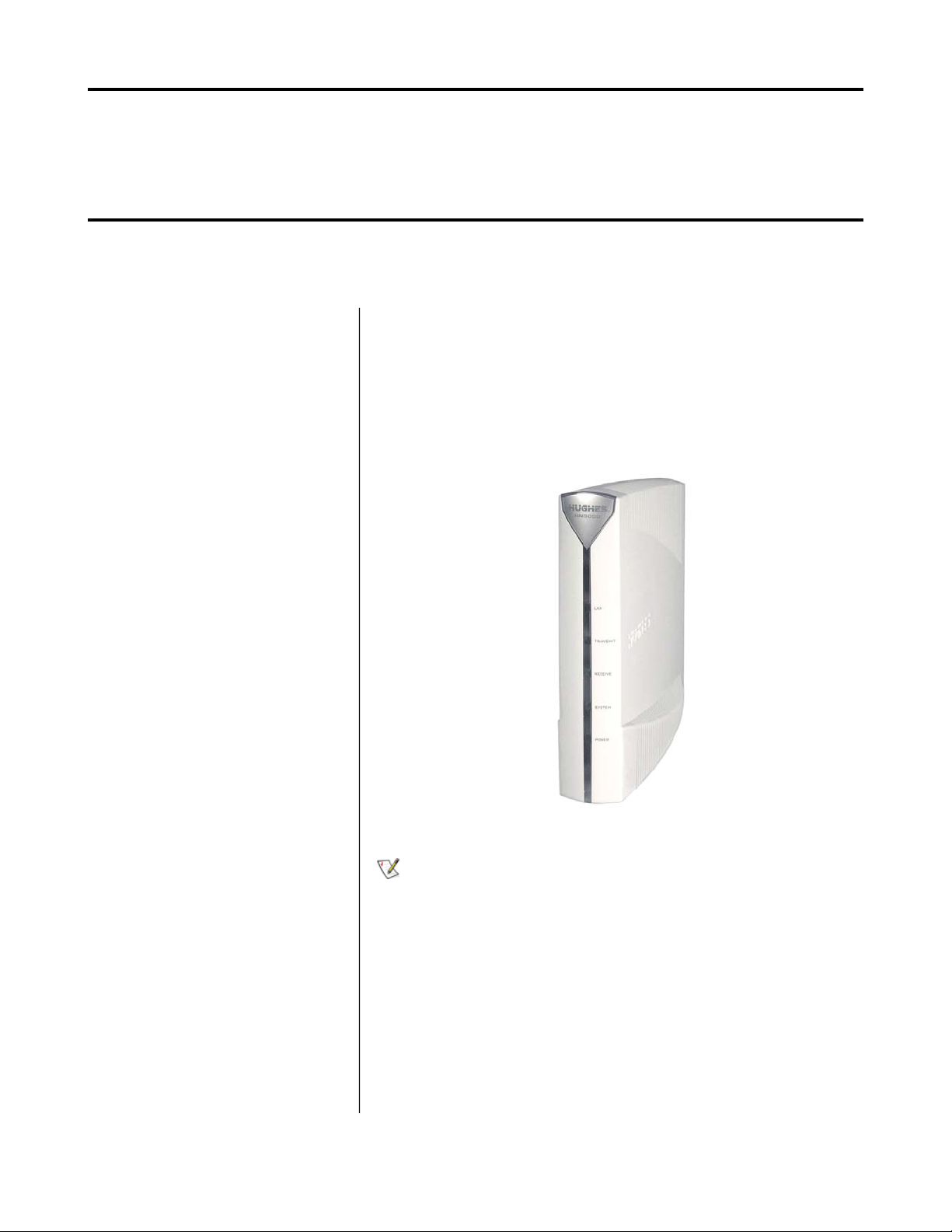
The HN9000 satellite modem connects to the Internet or an intranet by satellite
and provides Internet or intranet service to a single host, typically a computer,
or to multiple hosts on a LAN. A host may be a computer using Windows or
other supported operating system.
The modem is a self-hosted unit, meaning that it does not depend on a computer
to establish and maintain the Internet or intranet connection. However, the
modem must be connected to a properly aligned satellite antenna. The modem
has an Ethernet port so it can be connected to a computer or to an Ethernet LAN.
Figure 1: HN9000 satellite modem
Note: Acronyms used in this User Guide are identied in Acronyms used
in this Guide on page lxv.
After your HN9000 satellite modem has been installed, you can use a web
browser on your computer to access the Internet or an intranet. You can use a
local area network (LAN) to extend Internet or intranet connectivity to multiple
computers. This requires a properly congured NIC, an Ethernet cable or wireless
connection to the LAN, and proper conguration of the computer’s operating
system network properties.
The modem has a System Control Center that provides access to system
information such as the modem's IP address and subnet mask. You may need
this information to congure a network. The System Control Center is described
in System Control Center on page 7.
1
Page 16
Chapter 1
1037577-0001 Rev. A
Satellite modem overviewHN9000 Satellite Modem User Guide –
Supported configurations
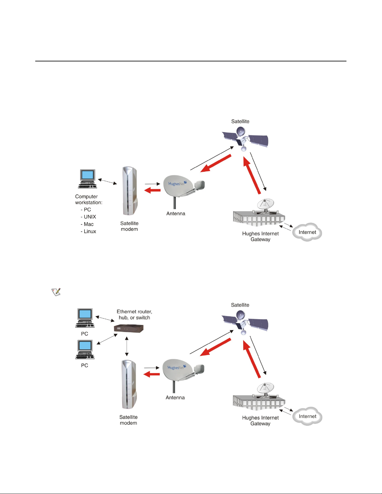
This section shows examples of supported congurations using the HN9000 satellite modem.
The satellite modem may be used in a single-host conguration or multiple-host conguration. In a single-host
conguration, the satellite modem is directly connected to the host (a computer), as shown in Figure 2: Single-host
conguration on page 2. The Hughes Internet Gateway is a Hughes-operated satellite station that provides a connection
between the Internet and the satellite. The gateway routes data to and from the Internet and to and from the satellite,
which in turn beams a signal down to the satellite modem to provide Internet connectivity.
Figure 2: Single-host configuration
In a multiple-host conguration, the hosts on the LAN share satellite Internet or internet connectivity through an Ethernet
hub, router, or wireless base station. The satellite modem is connected to the hub, router, or wireless base station, as
shown in Figure 3: Multiple-host conguration in an Ethernet wired LAN on page 2.
Note: You must provide and congure hub, router, or wireless base station equipment if any of these are used.
Figure 3: Multiple-host configuration in an Ethernet wired LAN
2
Page 17
Satellite modem overview
1037577-0001 Rev. A
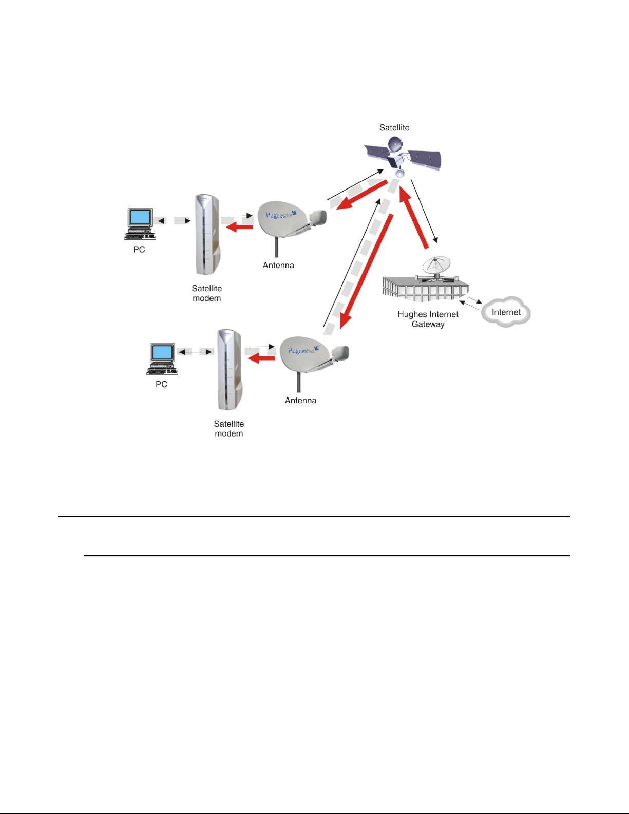
Figure 4: Private network conguration on page 3 shows a private network using two satellite modems at two locations.
The thick broken line shows how the network connects a PC at one location and to a PC at a second location. This
conguration requires two antennas—one at each location. The Hughes Internet Gateway connection is optional and is
based upon the network design for the customer private network. Typically this type of conguration is used only in
enterprise (business) environments.
Chapter 1HN9000 Satellite Modem User Guide –
Figure 4: Private network configuration
Satellite modem specifications
Table 1: Specifications for the HN9000 satellite modem
Safe operating temperature range
Protocol support
1.6 lb (0.73 kg)Weight
2.4 inch (6.1 cm)Width
7.8 inch (19.8 cm)Height
9.0 inch (22.9 cm)Depth
5 to 40º C (Above 5000 ft altitude, the maximum
temperature is reduced by 1º C per 1000 ft.)
5% to 95% non-condensingSafe operating humidity range
Up to 10,000 ftSafe altitude
ConvectionCooling method
TCP/IP (Transmission Control Protocol / Internet Protocol)
protocol suite
3
Page 18
Chapter 1
1037577-0001 Rev. A
Satellite modem overviewHN9000 Satellite Modem User Guide –
Interface ports
Power supplies and power requirements
Power supply information
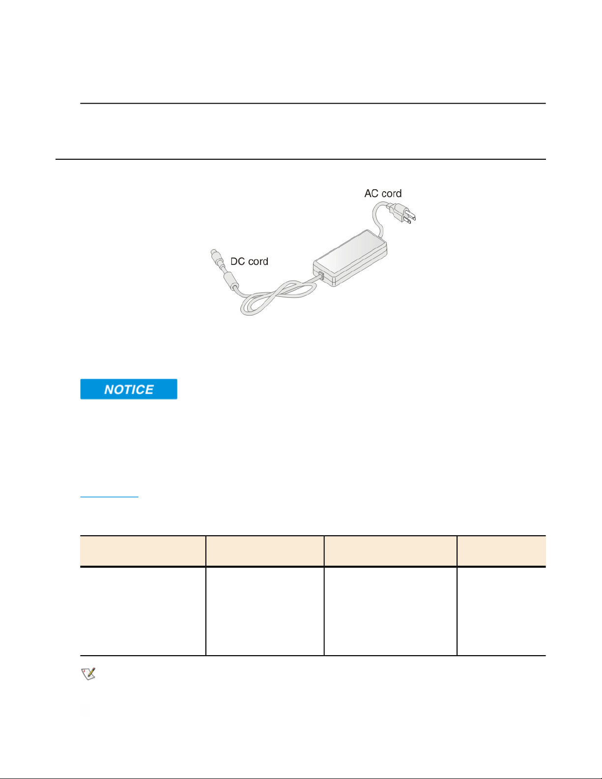
The power supply is included in the satellite modem shipping carton.
Figure 5: Power supply for the HN9000 satellite modem
One Ethernet port supporting 10BaseT or 100BaseT
operation, RJ-45-switched
See Power supply information on page 4.
Before proceeding, make sure you have the correct power supply. Check the part number on the power supply and refer
to Table 2: Power supply specications for the HN9000 satellite modem on page 4.
• Always use the power supply provided with the satellite modem. The modem's performance may suffer if the wrong
power supply is used.
• The input must be 110/130 VAC.
• A suitable surge protector is recommended to protect the satellite modem from possible damage due to power surges.
• If the satellite modem is installed outside the United States or Canada, observe the power standards and requirements
of the country where it is installed.
Table 2: Power supply specifications for the HN9000 satellite modem
Power supply type and part
number
AC/DC, 73 W
P/N 1501006-0001
HN9000 satellite modem
with 1-W or 2-W radio
Input line voltage:
100 – 130 V, 2 A maximum
Power cordElectrical requirementsApplication
Detachable, for 110
VAC outlet type.
Input line frequency:
60 Hz AC
Rated power consumption: 73 W
Note: The satellite modem should be continuously powered on unless it will not be used for an extended period.
4
Page 19
Satellite modem overview
1037577-0001 Rev. A
If there is any reason to remove power from the satellite modem, always unplug the AC power cord from the power
source (power outlet, power strip, or surge protector). Do not remove the DC power cord from the modem’s rear panel.
Doing so could result in an electrical shock or damage the modem.
When you re-apply power to the modem, plug the AC power cord into the power source.
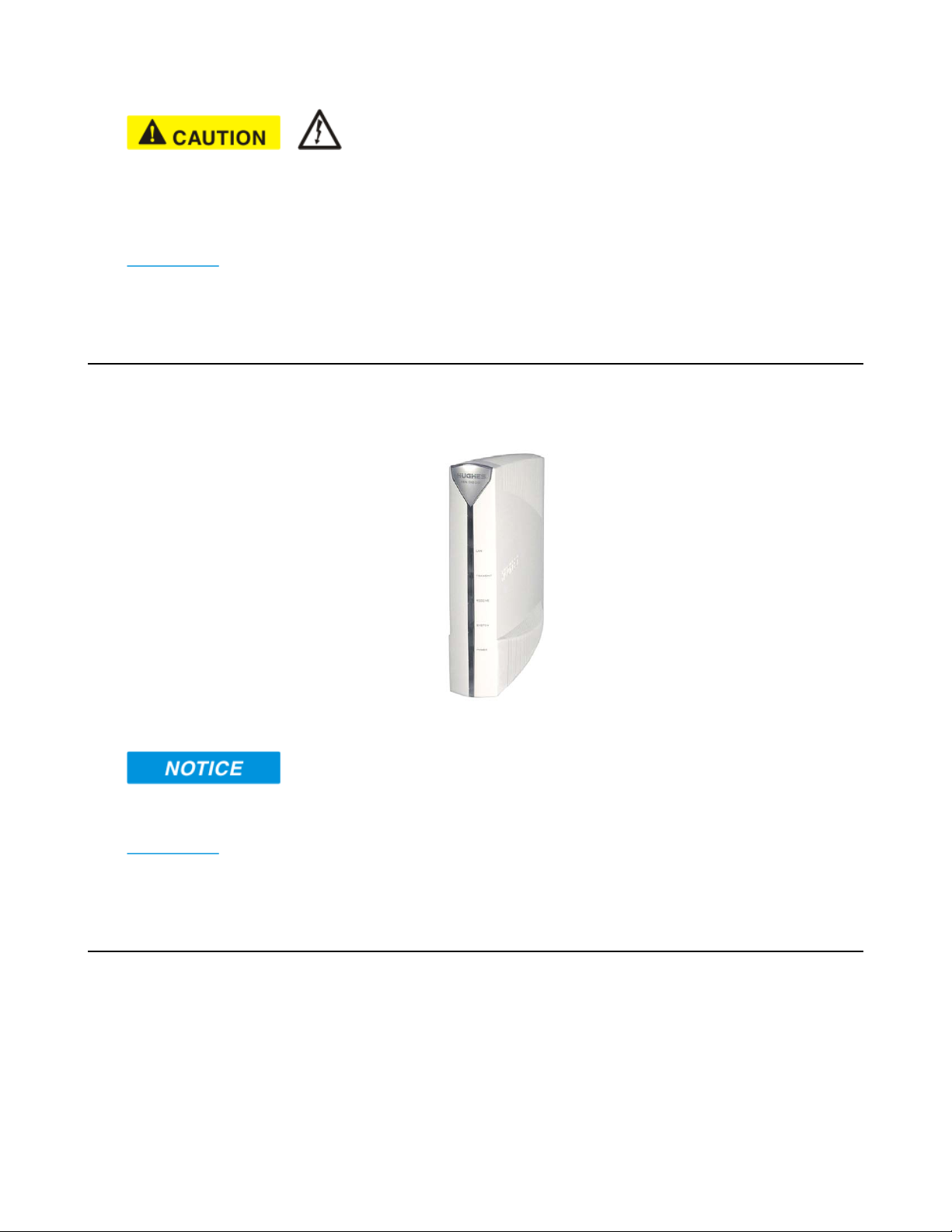
Modem operating position
Operate the HN9000 modem only in a vertical position, that is, resting on its built-in base as shown in Figure 6: HN9000
in vertical position on page 5. In any other position, the modem may overheat and malfunction because of inadequate
ventilation.
Chapter 1HN9000 Satellite Modem User Guide –
Figure 6: HN9000 in vertical position
To avoid overheating, operate the HN9000 modem only in the upright vertical position as shown in Figure 6: HN9000
in vertical position on page 5.
Computer requirements
The computer that connects to the satellite modem must meet the following minimum requirements. Requirements are
listed by operating system.
All requirements are minimum requirements except those identied as recommended.
The satellite modem may work with a computer that does not meet these requirements, but Hughes supports only
computers that meet these requirements. When your HughesNet service was activated, the activation software automatically
checked your computer to make sure it meets the minimum requirements. If it did not meet all requirements, but nearly
did, you may have been given a choice to proceed with service activation anyway.
5
Page 20

Chapter 1
1037577-0001 Rev. A
Microsoft Windows Vista Home Basic
• Processor speed: 800 MHz
• System memory: 512 MB
• Free hard disk space: 150 MB
Microsoft Windows Vista Home Premium, Business, Enterprise, or Ultimate
• Processor speed: 1 GHz
• System memory: 1 GB
• Free hard disk space: 150 MB
Microsoft Windows XP, Professional or Home Edition
•
Processor speed: 233 MHz. Recommended: 300 MHz or higher
•
System memory: 128 MB. Recommended: 256 MB or more
• Free hard disk space: 150 MB
Microsoft Windows 2000, Professional Edition with Service Pack 4
• Processor speed: 133 MHz
• System memory: 128 MB
• Free hard disk space: 150 MB
Satellite modem overviewHN9000 Satellite Modem User Guide –
Apple Mac 9.0-10.5 (excludes 10.0)
• Processor speed: 300 MHz
• System memory: 128 MB
• Free hard disk space: 150 MB
Networking requirements
• Ethernet port
• Ethernet cable (provided)
• Ethernet NIC, 10/100 Mbps, congured as follows:
• Auto-negotiate
• DHCP enabled
• Obtain an IP address automatically
Note: The computer can be congured to use a public IP address if the HughesNet service plan provides for
one or more public IP addresses.
Internet browser
• Internet Explorer 6 or greater, Netscape Navigator, Mozilla Firefox, Safari (for Windows and Mac)
• Browser settings:
• HTTP 1.1 or greater enabled
• Proxy settings disabled
6
Page 21

Chapter
2
System Control Center
Topics:
• Accessing the System Control
Center
• System Control Center home
page
• System Control Center common
features
• System Status page
• Reception Information page
• Transmission Information page
• Terminal Status page
• System Information page
• State codes
• Connectivity Test page
The System Control Center is a set of screens and links you can use to monitor
your broadband service and troubleshoot the satellite modem in the event of a
problem. The System Control Center provides access to system status,
conguration information, and online documentation through a web browser
on the computer that is connected to the satellite modem. Use the System Control
Center to nd system information for conguring networks or to check system
performance if the satellite modem does not seem to be functioning properly.
7
Page 22
Chapter 2
1037577-0001 Rev. A
System Control CenterHN9000 Satellite Modem User Guide –
Accessing the System Control Center
To open the System Control Center on a web browser installed on a computer that is connected to the satellite modem,
double-click the System Control Center shortcut on your computer desktop, or follow these steps:
1.
Open a web browser such as Internet Explorer or Netscape.
2.
In the browser address bar, type www.systemcontrolcenter.com or 192.168.0.1 and press Enter.
Note: To use 192.168.0.1, the satellite modem must be congured for a private address, and DHCP must be
enabled on the computer.
The System Control Center home page appears as shown in Figure 8: System Control Center home page on page
9.
If you are unable to access the System Control Center, refer to Cannot Access the System Control Center on page
34.
Creating a shortcut to the System Control Center
You can create a Windows shortcut on your computer desktop for easy access to the System Control Center home page.
Note: As part of the installation process, the person who installed your satellite modem creates a shortcut to the
System Control Center, so there should already be a shortcut on your desktop—unless it has been deleted.
1.
Open a web browser.
Note: The method described here works for Internet Explorer and Netscape Navigator. It may work with other
browsers.
2.
Type www.systemcontrolcenter.com or 192.168.0.1 in the browser address bar and press Enter.
Note: To use 192.168.0.1, the satellite modem must be congured for a private IP address, and DHCP must
be enabled on the computer.
The System Control Center home page appears.
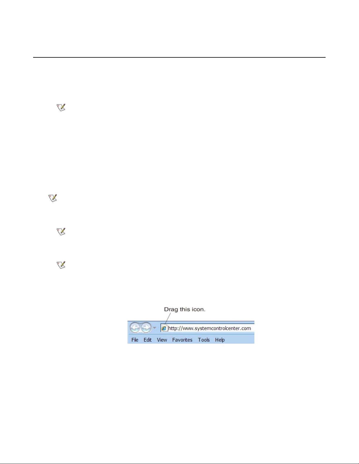
3.
Drag the icon that appears in front of the address displayed in the browser to the computer desktop.
Figure 7: Icon for creating shortcut
8
Page 23
System Control Center
1037577-0001 Rev. A
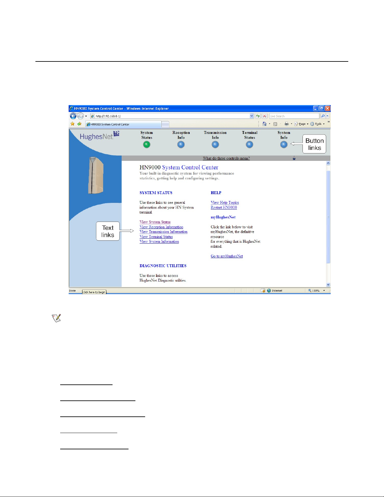
System Control Center home page
The System Control Center home page contains numerous links to satellite modem features and important information
regarding the operation of the satellite modem.
The button links at the top of the page appear on all System Control Center screens and are explained in Button links on
page 11.
Chapter 2HN9000 Satellite Modem User Guide –
Figure 8: System Control Center home page
Note: On some screens you may see the word terminal. This word refers to the satellite modem.
Text links
The System Control Center home page includes the following text links:
System Status links
• View System Status – Opens the System Status page, which displays general system status information such as
signal strength and administrative status.
• View Reception Information – Opens the Reception Information page, which displays information on data received
by the satellite modem.
• View Transmission Information – Opens the Transmission Information page, which displays information on data
transmitted by the satellite modem.
• View Terminal Status – Opens the Terminal Status page, which displays detailed information about the operational
status of the satellite modem such as interface packet counts and acceleration statistics.
• View System Information – Opens the System Information page, which displays information such as modem
identication information and IP address information.
9
Page 24

Chapter 2
1037577-0001 Rev. A
System Control CenterHN9000 Satellite Modem User Guide –
Note: These links take you to the same destinations as the button links at the top of each System Control Center
page.
Diagnostic utilities link
Connectivity Test – Opens the Connectivity Test page, which can be used to test the connection between the satellite
modem and the satellite. If you can access the satellite, there is no problem with your physical site connectivity between
the modem (inside) and the radio assembly and antenna (outside). See Connectivity Test page on page 23.
Help link
View Help Topics – Opens the Help page, which includes a variety of topics such as recommended browser and TCP/IP
settings.
Restart HN9000 restarts the satellite modem.
myHughesNet
Go to myHughesNet provides access to the HughesNet Web Portal, which contains a variety of useful tools, resources,
and information. Access to the HughesNet portal is determined by your specic service plan.
From the HughesNet portal you can click the HughesNet Customer Care link to access a wide variety of support
resources. For example, you can check online usage, test satellite speed, nd troubleshooting scripts, manage passwords,
access email, check your account and service plan information, and more. The specic portal information and available
features are determined by your specic service plan.
System Control Center common features
Certain features are common to some or all of the System Control Center screens, as shown in Figure 9: Common
features on System Control Center screens on page 11. These features and other common features are explained in the
following sections.
10
Page 25
System Control Center
1037577-0001 Rev. A
Chapter 2HN9000 Satellite Modem User Guide –
Figure 9: Common features on System Control Center screens
Button links
At the top of each System Control Center page are ve round buttons with labels above them as shown in Figure 10:
System Control Center button links on page 11. These ve buttons appear at the top of every System Control Center
page to provide an easy means of navigation. Each button is a link to the System Control Center page identied by the
label—for example, the System Status is a link to the System Status page.
The System Status and System Info buttons are always visible; the remaining three buttons are visible only after the
modem has been commissioned and is operational.
Figure 10: System Control Center button links
Click the button to go to the page identied by the label.
The destination page for each button link is identied below:
Table 3: Button links on System Control Center screens
Description of destination pageDestinationButton
System Status pageSystem Status
Displays general status information such as signal strength and
commissioning status. For more information see System Status
page on page 14.
11
Page 26

Chapter 2
1037577-0001 Rev. A
System Control CenterHN9000 Satellite Modem User Guide –
Description of destination pageDestinationButton
Reception Information pageReception Info
Displays statistics about received data and receive connection
status. For more information see Reception Information page
on page 15.
Transmission Information pageTransmission Info
Displays statistics about the transmitted data and transmit
connection status. For more information see Transmission
Information page on page 16.
Terminal Status pageTerminal Status
Displays detailed information about the operational status of
the satellite modem. For more information see Terminal Status
page on page 17.
System Information pageSystem Info
Displays system information such as ST Name (assigned name
of the satellite modem name) and operational software version.
For more information see System Information page on page
19.
System Status button
The System Status button (only) is a status indicator as well as a link. It changes color to indicate the satellite modem's
current status, as explained in Table 4: Meaning of System Status button colors on page 12. To see more detailed status
information, click the System Status button to open the System Status page.
Table 4: Meaning of System Status button colors
Green
Yellow
Orange
Red
MeaningButton color
OK – The satellite modem is operating normally.
Degraded – Degraded means performance is degraded for any of the following reasons:
• The Web Acceleration not functioning or in progress. Web Acceleration may be
temporarily inactive while you are browsing on a secure HTTP site (https).
• The modem is in fallback mode.
• A number of transmissions beyond a certain threshold have not been received by
the satellite (state code 30). This could be caused by weather conditions.
FAP threshold exceeded – The satellite modem has exceeded the FAP threshold specied
in the HughesNet service plan. Subscribers who exceed the threshold experience reduced
download speeds for approximately 24 hr.
Problem detected – There is a problem with satellite transmit or receive connectivity
or both.
If the System Status button is red or yellow , you can look for a red ag next to any value or values on the System
Control Center information pages (those with tables listing parameters and values). The red ag indicates a problem
related to the parameter listed next to the agged value. Click the parameter name to see a pop-up window that may
include helpful information, depending on what the problem is.
12
Page 27

System Control Center
1037577-0001 Rev. A
Links in left panel
The following links appear in the left panel of each System Control Center page (except the home page):
• Home – Opens the System Control Center home page.
• Connectivity Test – Opens the Connectivity Test page, which allows you to test the connection between the modem
and the satellite. See Connectivity Test page on page 23.
• Help – Opens the Help page. Refer to the Help page, which includes a variety of topics such as getting started and
recommended browser settings.
Status and information screens
Five of the System Control Center screens list status and operational parameters and their current values in a tabular
format. For example, the following illustration shows the Transmission Information page. The left column identies the
parameter category, the middle column lists the parameters, and the right column shows the current value of the parameter
listed in the middle column. Parameters are listed in this format on all ve status and information screens, which are
listed below:
• System Status page
• Reception Information page
• Transmission Information page
• Terminal Status page
• System Information page
Chapter 2HN9000 Satellite Modem User Guide –
Figure 11: Format of status and information screens
Each status and information screen contains categories of parameters that relate to various aspects of satellite modem
operation, as explained in the sections that follow for each status and information screen. To see a denition of any
parameter, click the parameter name. The denition appears in a pop-up window. For many parameters this window
13
Page 28

Chapter 2
1037577-0001 Rev. A
System Control CenterHN9000 Satellite Modem User Guide –
also includes additional information. If you do not see the pop-up window, it may be hidden by other windows; in this
case, minimize other open windows.
State codes on status and information screens
A state code is a number that indicates the operational state of the satellite modem. State codes are displayed with an
explanation in words, as shown in the following example. On the System Control Center status and information screens,
state codes are shown next to selected parameters, as shown in Figure 12: Example of a state code on page 14, or next
to a parameter that is related to an error condition.
Figure 12: Example of a state code
For a list and explanation of all state codes, see Table 5: State codes on page 20.
Red flag indicator
On the status and information screens, a red ag next to a value indicates a problem related to the parameter listed in
the same row where the agged value appears. The agged value appears in the right column; the parameter appears in
the middle column. The value indicates the current state of the parameter.
The red ag may help you or a Hughes Customer Care representative identify and troubleshoot a problem. If you see a
red ag, click the parameter name. The pop-up window that appears may include troubleshooting information.
Figure 13: Red flag problem indicator
System Status page
The System Status page displays important information about the satellite modem's operational status.
Available system status values may vary, depending on how the satellite modem is congured. Therefore, some options
shown in Figure 14: System Status page on page 15 may not appear on your System Status screen.
The System Status page and other System Control Center pages show information that may be particularly useful for
advanced users and for troubleshooting.
14
Page 29

System Control Center
1037577-0001 Rev. A
Chapter 2HN9000 Satellite Modem User Guide –
Figure 14: System Status page
The operational parameters listed on the System Status page are shown in a tabular format. The rst (left) column
identies the parameter categories:
• Satellite Interface – Contains information on the receive status and signal strength, as well as error messages related
to satellite modem receive information.
• Administrative States – Contains information on software downloads to this satellite modem, security keys, and
other administrative functions.
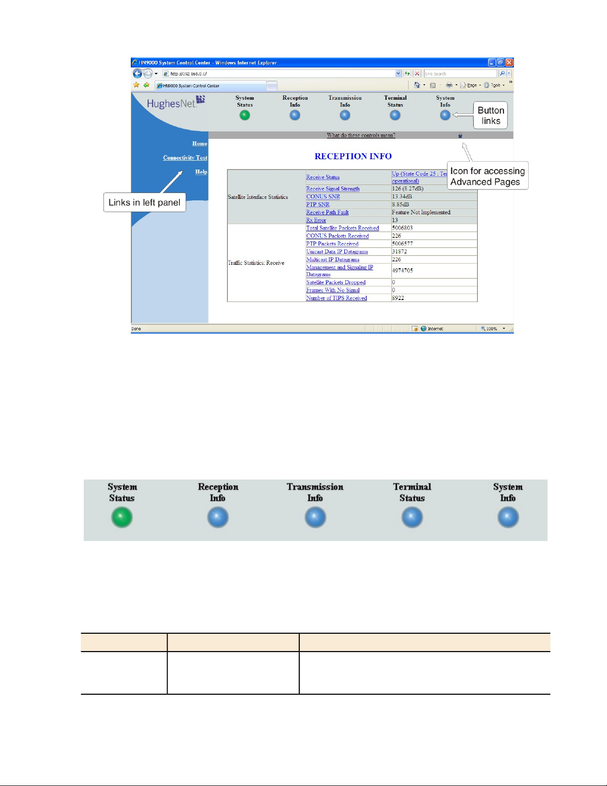
Reception Information page
The Reception Information page shown in Figure 15: Reception Information page on page 16 displays information
about data received by the satellite modem.
15
Page 30

Chapter 2
1037577-0001 Rev. A
System Control CenterHN9000 Satellite Modem User Guide –
Figure 15: Reception Information page
The operational parameters listed on the Reception Information page are shown in a tabular format. The rst (left)
column identies the parameter categories:
• Satellite Interface Statistics – Contains information on the receive status and signal strength, as well as error messages
related to satellite modem receive information.
• Trafc Statistics: Receive – Contains statistical information on data received from the satellite including number of
packets received or dropped, etc.
Information about selected parameters
This section provides information for selected parameters on the Reception Information page. Parameters that may be
most useful for you to know about are listed.
Total Satellite Packets Received – An increasing count of Total Satellite Packets Received indicates that your satellite
modem is successfully receiving data.
Transmission Information page
The Transmission Information page shown in Figure 16: Transmission Information page on page 17 displays information
about data transmissions from the satellite modem. The information on this screen may be useful to a Hughes Customer
Care representative if you need help in resolving a problem.
16
Page 31

System Control Center
1037577-0001 Rev. A
Chapter 2HN9000 Satellite Modem User Guide –
Figure 16: Transmission Information page
The operational parameters listed on the Transmission Information page are shown in a tabular format. The rst (left)
column identies the parameter categories:
• Satellite Interface Statistics – Contains information on transmit status and signal strength, as well as
transmission-related error messages.
• Trafc Statistics: Transmit – Contains statistical information on the specic data transmitted to the satellite from
this satellite modem.
Information about selected parameters
This section provides information for selected parameters on the Transmission Information page. Parameters that may
be most useful for you to know about are listed.
Total Satellite Packets Transmitted – An increasing count of Total Satellite Packets Transmitted indicates that your
satellite modem is successfully transmitting data.
Terminal Status page
The Terminal Status page displays information about the operational state of the satellite modem and operational statistics
such as messages and packets sent, received, and dropped. It indicates whether acceleration is enabled and provides a
count of trafc that moves across the LAN to the satellite modem.
17
Page 32

Chapter 2
1037577-0001 Rev. A
System Control CenterHN9000 Satellite Modem User Guide –
Figure 17: Terminal Status page (top part)
The operational parameters listed on the Terminal Status page are shown in a tabular format. The rst (left) column
identies the parameter categories:
• Overall Status – Shows the major features such as dial backup or acceleration (not all features may be part of your
service plan.
• Transport Interface Receive Statistics – Indicates messages received and decoded by the satellite modem from the
satellite.
• Transport Interface Transmit Statistics – Indicates messages being queued up by the satellite modem for transmission
to the satellite.
• LAN Interface Statistics – Shows trafc across the LAN interface to the satellite modem.
• IP Forwarding and Routing Statistics – These refer to system control messages.
• Local IP Interface Statistics – Sum of various counts of messages.
• Dial Backup Status – Count of dial backup trafc if the feature is enabled. (Some listed features may not be included
in your service plan.)
• TCP Acceleration Statistics – Counts of messages and connections used between the satellite modem and its destination
if the feature is enabled. (Some listed features may not be included in your service plan.)
• SSL Acceleration Statistics – Counts of SSL trafc if the feature is enabled. (Some listed features may not be included
in your service plan.)
• DNS Caching Statistics – Counts on local storage of data if the feature is enabled. (Some listed features may not be
included in your service plan.)
• Management Statistics – Various internal network management trafc counts.
• Turbo Page Statistics – Counts of various web page requests and objects if the feature is enabled. (Some listed features
may not be included in your service plan.)
18
Page 33

System Control Center
1037577-0001 Rev. A
Information about selected parameters
This section provides information for selected parameters on the Terminal Status page. Parameters that may be most
useful for you to know about are listed.
The Dial Backup Status parameter and Dial Backup Status category of parameters do not apply to the HN9000 satellite
modem.
System Information page
The System Information page shown in Figure 17: Terminal Status page (top part) on page 19 provides system
information for the satellite modem such as ST name (modem name), Site ID (Site Id), and operational software version.
Chapter 2HN9000 Satellite Modem User Guide –
Figure 18: System Information page (top part)
Note: Print the System Information page and save it. Click Print this page next to the printer icon. If you experience
a problem with your satellite modem this page may not be accessible. Information on this screen may be useful to
a Hughes Customer Care representative in helping you to resolve the problem.
The operational parameters listed on the System Information page are shown in a tabular format. The rst (left) column
identies the parameter categories:
• Identication – Contains system ID information such as Site ID (installation site ID) and ST name (a unique name
that identies the satellite modem).
• Software – Contains version information on the various software applications resident on the satellite modem such
as commissioning and operational software. (Commissioning refers to initial start-up of the modem.)
• Satellite – Contains information pertaining to communication with the satellite such as antenna size, transmit radio
wattage, and uplink transmission mode.
19
Page 34

Chapter 2
1037577-0001 Rev. A
System Control CenterHN9000 Satellite Modem User Guide –
• Addressing – Contains addressing information such as LAN port address and subnet mask and available public IP
addresses (if any, depending on your service plan).
• Software Features – This section lists the optional features and provides information on whether they are currently
active. These features are enabled or disabled per your service plan and cannot be changed locally.
State codes
A state code is a number that indicates the operational state of the satellite modem. Some state codes indicate an error
condition. State codes are identied as State code followed by a number from 1 – 35. They are displayed with an
explanation in words, as shown in the following example.
State codes appear on screens displayed during a hard reboot (when power is removed and then restored) and on System
Control Center pages.
Figure 19: Examples of state codes
Table 5: State codes on page 20 lists and explains all HN9000 state codes.
In the state code table, modem refers to the satellite modem.
Table 5: State codes
Installation – Boot phase
1
Starting Up in Boot
phase.
2
Waiting for Installation
Parameters
installation parameters have not been
submitted.
3
Coarse Pointing in
Progress
(coarse or ne pointing). Occurs
during modem installation only.
Acquiring Beacon in Boot4
Occurs during Auto modem
replacement only: Modem is searching
for beacon.
5
Acquiring PTP SNR in
Boot
Occurs during Auto modem
replacement only: Modem is searching
for point-to-point signal.
Corrective actionExplanationState nameState code
Transient – No action is necessary.Satellite modem is starting up in boot
Transient – No action is necessary.Modem has not been installed, and
Transient – No action is necessary.Antenna pointing is in progress
Transient – No action is necessary.
Transient – No action is necessary.
6
Waiting for Uplink
Polarization Change
switch uplink polarization at the radio
Installer should switch polarization.Modem is waiting for installer to
assembly. Occurs during installation
only.
20
Page 35

System Control Center
1037577-0001 Rev. A
Chapter 2HN9000 Satellite Modem User Guide –
Corrective actionExplanationState nameState code
10
11
12
7
Downlink Established in
Boot
has been established; that is, beacon
Transient – No action is necessary.Modem is in boot phase. Downlink
is being tracked and transmission
information packets are being
received.
Waiting for MIPs in Boot8
Transient – No action is necessary.Modem is in boot phase and is waiting
for indirect and direct management
packets.
9
Downloading
Commissioning Software
downloading commissioning software.
Waiting for Antenna
Pointing Complete
pointing validation to complete.
Transient – No action is necessary.Modem is in boot phase and is
Installer must complete validation.Modem is waiting for antenna
Occurs during installation only.
Installation – Commissioning phase
Starting Up in
Commissioning
Downlink Established in
Commissioning
commissioning phase.
Downlink has been established; that
Transient – No action is necessary.Modem is starting up in
Transient – No action is necessary.Modem is in commissioning phase.
is, beacon is being tracked and
transmission information packets are
being received.
13
18
19
20
Waiting for MIPs in
Commissioning
Probing in Progress14
Probing Failure15
Registering ST16
ST Registration Failure17
Waiting for Capacity
Keys
Reconciling Proles in
Commissioning
Downloading Operational
Software
and is waiting for indirect and direct
management packets.
Probing is in progress. Occurs during
installation only.
Modem is in commissioning phase.
Probing has failed.
Modem is registering with the NOCC.
Modem is in commissioning phase:
registration with the NOCC has failed.
modem is waiting for capacity keys
from the NOCC.
modem is reconciling proles with the
NOCC.
and is downloading operational
software.
Transient – No action is necessary.Modem is in commissioning phase
Transient – No action is necessary.Modem is in commissioning phase.
Occurs only during installation.
Transient – No action is necessary.Modem is in commissioning phase.
Occurs only during installation.
Transient – No action is necessary.Modem is in commissioning phase;
Transient – No action is necessary.Modem is in commissioning phase;
Transient – No action is necessary.Modem is in commissioning phase
Note: State codes 1 – 20 appear only while the modem is being installed or during a hard reboot (resulting from power
being removed and then restored).
21
Page 36

Chapter 2
1037577-0001 Rev. A
System Control CenterHN9000 Satellite Modem User Guide –
Corrective actionExplanationState nameState code
Operational phase
22
23
24
25
Starting Up in Operation21
Downlink Established in
Operational
Waiting for MIPs in
Operational
Reconciling Prole in
Operational
operation)
Rx Connectivity Down26
phase.
Downlink has been established; that
is, beacon is being tracked and
transmission information packets are
being received.
waiting for indirect and direct
management packets.
Proles are being distributed to
various subsystems.
Error codes
Rx cable connectivity tests have
failed.
Transient – No action is necessary.Modem is starting up in operational
Transient – No action is necessary.Modem is in operational phase.
Transient – No action is necessary.Modem is in operational phase and is
Transient – No action is necessary.Modem is in operational phase.
Steady state – No action is necessary.Modem is fully operational.Fully Operational (normal
Make sure the SAT. IN and SAT.
OUT cable connections are nger
tight. If the problem persists, call your
service provider to verify cabling and
pointing.
Modem is unable to track beacon.No Beacon27
Call your service provider to verify
cabling and pointing.
No TIPs28
Modem is not receiving transmission
information packets from satellite.
Tx cable connectivity tests have failed.Tx Connectivity Down29
Call your service provider to verify
cabling and pointing.
Call your service provider to verify
cabling and pointing.
Too Many Bad Slots30
Bad slots are transmissions from the
modem that are not received by the
satellite. State code 30 indicates a
percentage of bad slots within the last
Rain or snow can cause this condition.
If it continues during clear weather,
call your service provider to verify
cabling and pointing.
hour that exceeds a preset value.
ECL Active31
Transmitter has been shut down due
to ECL. ECL measures total
transmitted power over 30- minute
periods and turns off the transmitter
if the total power exceeds a preset
Transient – No action is necessary.
Because home installations use lower
wattage radios, home users are not
likely to see this condition.
limit imposed by the FCC.
Restricted states (NOCC-imposed restrictions)
Barred32
Call your service provider.Modem has been barred from
transmitting by the NOCC. Possible
reasons for barring include
interference isolation, uplink failure,
or government order.
22
Page 37

System Control Center
1037577-0001 Rev. A
Chapter 2HN9000 Satellite Modem User Guide –
Corrective actionExplanationState nameState code
Suspended33
state by the NOCC. This occurs if a
customer’s bill is overdue or if service
is terminated.
Maintenance34
state by the NOCC.
Out of Service35
state by the NOCC.
Viewing the state codes list
To view a list of state codes with an explanation of each code:
1.
Click the underlined state code number.
Call your service provider.Modem has been put in a suspended
Call your service provider.Modem has been put in maintenance
Call your service provider.Modem has been put in out-of-service
A pop-up window appears that briey identies each state code. If you do not see the pop-up window, it may be
hidden by other windows; if this happens, minimize other open windows.
2.
Scroll down to see the entire list of state codes.
Connectivity Test page
You can use the Connectivity Test page to test the connection between the satellite modem and the satellite. Instructions
for the test are provided on the screen. No special conguration is required.
23
Page 38

Chapter 2
1037577-0001 Rev. A
System Control CenterHN9000 Satellite Modem User Guide –
Figure 20: Terminal Connectivity Test page
For details about this test, see Testing connectivity to the satellite on page 34.
24
Page 39

Chapter
3
HughesNet Tools
Topics:
• Launching HughesNet Tools
• HughesNet Tools home page
HughesNet Tools is a suite of software tools installed on the computer that is
connected to the satellite modem during service activation. If for any reason
HughesNet Tools is not installed on your computer, you can download it from
www.myhughesnet.com. (Click the HughesNet Customer Care link, click
Tools, and then clink the link to download HughesNet Tools.)
HughesNet Tools:
• Can help you solve Internet browsing problems.
• Provides enhanced Internet security and improved performance for your
computer.
• Provides convenient access to helpful support documents and phone numbers
for contacting Hughes Customer Care.
25
Page 40

Chapter 3
1037577-0001 Rev. A
Launching HughesNet Tools
To launch HughesNet Tools from the Windows Start menu, click Start Programs HughesNet Tools.
You can also launch HughesNet Tools by double-clicking the HughesNet Tools shortcut on your
computer desktop or by double-clicking the similar icon in the system tray in the lower right corner of your computer
screen.
The HughesNet Tools home page opens, as shown in Figure 21: HughesNet Tools home page on page 26.
HughesNet Tools home page
HughesNet ToolsHN9000 Satellite Modem User Guide –
The HughesNet Tools home page includes links to several useful tools, utilities, and information sites. Several of the
tools run automatic tests when you click the link.
Figure 21: HughesNet Tools home page
I Have a Technical Problem
I Have a Technical Problem includes the following links:
I am Unable to Browse the Internet – This tool tests your Internet connection. If the test fails, the tool suggests options
for solving the problem.
I Cannot Send or Receive Email – This tool tests your e-mail account, and attempts to correct the problem.
26
Page 41

HughesNet Tools
1037577-0001 Rev. A
Support Library
In the Support Library area of the screen, the link Browse All Support Documents helps you navigate to support
documents for Internet Explorer and Outlook Express and Hughes How to articles on various topics.
Helpful Tools
Helpful Tools includes the following links:
Utilities – These utilities can improve the performance of your computer and/or Internet browser.
Congure Your Email Client – This tool congures your computer to use any of several popular email programs.
Security – This tool takes certain steps to improve the security of your computer. It scans your computer to see what
security software is installed. It asks you if you would like to install a trial subscription to the ZoneAlarm Security Suite.
Contact Support – If you click the Contact Support link, HughesNet Tools automatically runs tests to see if it can
determine and correct any problems with your computer and Internet browser conguration. If it cannot nd and correct
any problems, HughesNet Tools presents a phone number you can call for assistance.
Chapter 3HN9000 Satellite Modem User Guide –
27
Page 42

Page 43

Chapter
4
LEDs
Topics:
• Front panel LEDs
• LAN port LEDs
The satellite modem has a vertical row of LEDs on the front panel and small
LEDs on the Ethernet port on the back of the modem. The LEDs provide
information about the satellite modem's operating status.
29
Page 44

Chapter 4
1037577-0001 Rev. A
Front panel LEDs
The satellite modem has ve LEDs on the front panel, as shown in Figure 22: Front panel LEDs on the HN9000 modem
on page 30. By their appearance—on, off, or blinking—the LEDs indicate the modem's operating status.
LEDsHN9000 Satellite Modem User Guide –
Figure 22: Front panel LEDs on the HN9000 modem
Table 6: Front panel LED indications on page 30 explains what the modem status is when the LEDs are on, off, or
blinking. On means the LED is continuously lit. Blinking means the LED is usually on, but intermittently turns off
briey.
Table 6: Front panel LED indications
Corrective actionSatellite modem statusAppearanceLED
OnLAN
The modem's LAN port is connected to another
network device such as your computer.
Off
Check network connections.Problem with the LAN conguration; requires
user intervention.
The modem is able to transmit.OnTransmit
Blinking
The modem is transmitting data packets to the
network satellite.
Check transmit cable connection.Problem in the transmit path.Off
Signal quality is good.OnReceive
Blinking
The modem is receiving data packets from the
satellite.
30
Page 45

LEDs
1037577-0001 Rev. A
Chapter 4HN9000 Satellite Modem User Guide –
Corrective actionSatellite modem statusAppearanceLED
Check receive cable connection.Problem in the receive path.Off
Ready to handle user trafc.OnSystem
In boot or commissioning phase.Blinking
Not ready to service user trafc.Off
On – bluePower
The satellite modem is receiving power from its
power supply.
On – red
Modem temperature is too hot.
(If the modem overheats, it turns off. When it
cools it recovers to operational status.)
Make sure the environmental
temperature is within range, that the
modem is positioned vertically, and
that its vents are not blocked.
Check power connection.Not receiving power.Off
Bold type indicates LED appearance during normal operation.
LAN port LEDs
Green and orange LEDs on the LAN (Ethernet) port on the modem's rear panel indicate link status and speed, as explained
in Figure 23: LAN port LEDs on page 31.
Figure 23: LAN port LEDs
31
Page 46

Page 47

Chapter
5
Troubleshooting
Topics:
• Cannot Access the System
Control Center
• Testing connectivity to the
satellite
• Hot cable connector
• Checking for viruses and firewall
issues
If you encounter a problem with the satellite modem, refer to the relevant
troubleshooting procedure or procedures in the sections that follow. If you cannot
correct the problem, contact Hughes Customer Care.
For support options and contact information, see Contact Information on page
xiii.
Improper settings on the computer connected to the satellite modem can cause
problems. For instructions on conguring a computer to work properly with the
modem see Computer settings on page 37.
33
Page 48

Chapter 5
1037577-0001 Rev. A
Cannot Access the System Control Center
Follow these steps if you cannot access the System Control Center after installation of the satellite modem.
1.
If the modem is using a private IP address, conrm that DHCP is enabled on the computer.
This procedure is explained in Conguring a computer to use DHCP on page 39.
2.
Open a web browser on a computer connected to the satellite modem.
3.
In the browser address bar, type www.systemcontrolcenter.com or 192.168.0.1 and press Enter.
Note: To use 192.168.0.1, the satellite modem must be congured for a private IP address, and DHCP must
be enabled on the computer.
If the System Control Center does not appear, continue with the remaining steps.
4.
Make sure that the satellite modem is powered up. The Power and LAN LEDs should be continuously lit—except
that the LAN LED may blink if there is LAN activity.
5.
Make sure the DC power cord adapter is securely attached to the satellite modem.
6.
If the LEDs are off, make sure the Ethernet cable is securely attached to the satellite modem and the computer.
7.
If you still cannot access the System Control Center, contact Hughes Customer Care for assistance.
TroubleshootingHN9000 Satellite Modem User Guide –
Testing connectivity to the satellite
If you have problems connecting to the Internet, you can use the Connectivity Test page to test connectivity between
the modem and the satellite. This connectivity test sends test messages on a loop from the modem to the satellite and
back to the modem, as shown in Figure 24: Satellite loopback connectivity test on page 34. If the test succeeds, it veries
that the modem can connect to the satellite.
Figure 24: Satellite loopback connectivity test
1.
To conduct this test from any System Control Center page, click Connectivity Test in the left panel.
The initial Terminal Connectivity Test page appears.
34
Page 49

Troubleshooting
2.
Click Start Test.
You may see a screen that asks you to wait while the test is conducted. When the test is completed, the Connectivity
Test results page appears.
1037577-0001 Rev. A
Chapter 5HN9000 Satellite Modem User Guide –
Figure 25: Terminal Connectivity Test page
Figure 26: Connectivity Test results page
If the number of messages sent equals the number of messages received, the test is successful—there is good
connectivity between the remote modem and the satellite.
If the number of messages received is greater than zero but not equal to the number of messages sent, you have
physical connectivity to the satellite, but if this test result persists, you may have an access problem.
Typically the delay time (time message is sent until it is received) is approximately 1 second. The screen shows the
minimum, average, and maximum delay times for the test messages in milliseconds. Most important is whether all
messages are received or not.
35
Page 50

Chapter 5
For additional information, see How to interpret these results on the test results page.
1037577-0001 Rev. A
Hot cable connector
If the connector on either the transmit or receive cable feels hot to the touch, the connector may be loose or otherwise
defective. Troubleshoot this problem as follows:
1.
Remove power from the satellite modem by unplugging the power supply AC power cord from the surge protector
or AC outlet.
To remove power from the satellite modem, always unplug the AC power cord from the power source (power outlet,
power strip, or surge protector). Do not remove the DC power cord from the modem's rear panel. Doing so could
result in an electrical shock or damage to the modem.
2.
Allow the cable connector to cool for at least 5 min.
3.
Make sure the cable connector feels cool.
4.
Make sure the connector is securely attached to the cable and properly aligned. If it is cross-threaded, remove it and
reattach it. The connector should be nger tight with no play.
TroubleshootingHN9000 Satellite Modem User Guide –
Note: The satellite modem may operate correctly when rst installed, even if the transmit and receive cable
connectors are not adequately tightened. However, problems could develop later. Therefore, correct operation
of the modem is not an indication that the cables are adequately tightened.
5.
Reapply power to the modem by plugging the power supply back into the surge protector or AC outlet.
A suitable surge protector is recommended to protect the satellite modem from possible damage due to power surges.
6.
Wait 5 min.
7.
Check the connector to see if it is hot.
If the connector is still hot, it may be defective and should be replaced.
Checking for viruses and firewall issues
If you have conrmed all connections but still cannot access the Internet, check the computer (and any other computers
on the same network) for viruses. If you nd a virus, delete or disable it, then try to browse the Internet again.
If you are using a rewall, refer to the rewall documentation and make sure none of its settings are blocking access to
either the Internet or the Hughes servers. Make sure you are using the latest version of any anti-virus and/or rewall
software.
36
Page 51

Chapter
6
Computer settings
Topics:
• Understanding the modem
address and computer address
• Configuring a computer to use
DHCP
• Configuring a computer for a
public IP address
• Configuring proxy settings
For proper operation of the satellite modem, you may have to change certain
settings on the computer that is connected to the modem.
Instructions are provided for:
• Conguring a computer to support DHCP
• Conguring a computer to use a public IP address
• Disabling a web browser's proxy connection
These procedures are explained in the sections that follow.
37
Page 52

Chapter 6
1037577-0001 Rev. A
Understanding the modem address and computer address
The satellite modem and any computer or computers that connect to it must each have their own identifying network
address. This network address is known as an IP address. An IP address may be dynamic, meaning that it can change,
or static, meaning that it is xed—it does not change. An IP address may also be public (or routable), meaning that it
can be used on the Intranet. A private IP address works on an internal network but not over the Internet. However, to
gain access to the Internet, private addresses may be converted by a network address translation (NAT) service to a
public IP address that can be used on the Internet. Both private and public addresses can be dynamic or static, although
typically a private IP address is dynamic and a typically a public IP address is static.
Both the modem and a connected computer can have either type of address—private or public. The type used depends
on requirements a customer might have and their service plan. A public IP address or addresses are available only if
they are specied in the service plan. Typically home users use a private IP address, but some home users use a public
IP address.
To nd specic address information, go to the System Control Center System Information page Figure 17: Terminal
Status page (top part) on page 19. Scroll down until you see Addressing in the left column. Look at the rst three
parameters in the Addressing eld, as shown in the following two examples.
Computer settingsHN9000 Satellite Modem User Guide –
Private IP addresses
Figure Figure 27: Example of Addressing parameters showing available private IP addresses on page 38 is an example
of System Information page address parameters for a satellite modem with a service plan that provides private IP
addresses.
Figure 27: Example of Addressing parameters showing available private IP addresses
In this example, the satellite modem is assigned a private IP address (LAN Port Address) of 192.168.0.1.
There are 253 available private IP addresses that can be assigned to computers connecting to the satellite modem. These
addresses are in the range from 192.168.0.2 to 192.168.0.254 (the Last Usable IP Address).
Public IP address
Figure Figure 28: Example of Addressing parameters showing one available public IP address on page 38 is an example
of System Information page address parameters for a satellite modem with a service plan that provides one public IP
address. Some service plans provide multiple public IP addresses.
Figure 28: Example of Addressing parameters showing one available public IP address
In this example, the satellite modem is assigned the public IP address (LAN Port Address) 97.73.73.65. The modem’s
DHCP server has only one public IP address to assign to a connecting computer: 97.73.73.66 (the Last Usable IP Address).
38
Page 53

Computer settings
1037577-0001 Rev. A
For instructions on conguring a public IP address on your computer, see the applicable section in Conguring a computer
for a public IP address on page 47. Find the section that applies to your computer operating system.
Multiple public IP addresses
If a service plan provides more than one public IP address, the range (or difference) from the LAN Port Address to the
Last Usable IP Address will be greater than one. For example, if the LAN Port Address is 97.73.73.65 and the Last
Usable IP Address is 97.73.73.70, the range (or difference) is 5, meaning there are ve available public IP addresses.
If you don't know the modem’s public IP address…
To access the satellite modem when the service plan provides a public IP address, you need to know the public IP address
of the satellite modem (the LAN Port Address). If you do not know the LAN Port Address (and you cannot access the
System Information page), you can set a link local address on your computer as explained below:
1.
Use the Windows Control Panel on the connected computer to open the Local Area Connection Properties dialog
and then the Internet Protocol (TCP/IP) Properties dialog. If you need more specic instructions, see Conguring a
computer for a public IP address on page 47.
2.
In the Internet Protocol Properties dialog, click Use the following IP address.
3.
Enter the following:
a)
In the IP address eld, type 169.254.10.10.
b)
Typically the Subnet mask eld auto-populates to 255.255.0.0. If it does not, enter this value manually.
c)
In the Default gateway eld, type 169.254.0.1.
d)
In the Preferred DNS server eld, type 66.82.4.8.
e) Click OK twice to close the Internet Protocol Properties dialog and the Network Connections dialog.
Chapter 6HN9000 Satellite Modem User Guide –
4.
With the computer congured as instructed above, type 169.254.0.1in your browser address window to open the
System Control Center.
If you click the link on the System Control Center home page for the System Information page, you can read the
modem's IP address in the Addressing section. The LAN Port Address is the modem's IP address.
5.
Record the LAN Port Address and the Last Usable IP Address.
Now you can enable DHCP on your computer (by selecting Obtain an IP Address automatically in the Internet
Protocol Properties dialog). Then, the modem will dynamically assign a public IP address to the computer.
Alternatively, if you want to assign a particular public IP address to your computer, you can set that public IP address
on your computer. To congure the public address, see Conguring a computer for a public IP address on page 47.
Configuring a computer to use DHCP
DHCP is a protocol that allows a computer to obtain its IP address from a DHCP server on a network when the computer
connects to the network. This type of IP address is called a dynamically assigned IP address because it can change when
the computer disconnects from the network and later re-connects.
The satellite modem incorporates a DHCP server (always enabled) to assign IP addresses to computers that connect to
it. The modem can assign private IP addresses or public IP addresses, depending on the service plan purchased by the
satellite modem customer.
In most cases, DCHP should be enabled on a computer or computers that connect to the satellite modem so the computer(s)
can ask for and receive an IP address (private or public) from the satellite modem DHCP server.
DHCP should be disabled on your PC if you have purchased a service plan with a public IP address(es) and want to use
a public IP address.
39
Page 54

Chapter 6
1037577-0001 Rev. A
The following sections explain how to congure computers with various operating systems to use DHCP in the event
that DHCP is disabled on the computer. To enable DHCP, use the instructions for your specic computer operating
system.
If you are using the satellite modem as part of a network, you should have already installed either an Ethernet hub or a
wireless base station and NICs in each computer on the LAN. If necessary, you should have also connected the computers
to the Ethernet hub with an Ethernet cable. See Home networking on page 57 for more information.
Configuring Windows Vista to use DHCP
This section explains how to congure your computer to use DHCP if your computer operating system is Microsoft
Windows Vista.
1.
From the Windows desktop, select Start Settings Network Connections.
A list of network adapters appears as shown in Figure 29: Network connections – Windows Vista on page 40. The
Local Area Connection-NIC Card icon must appear under the LAN or High-Speed Internet heading. If it does not,
the network is not installed correctly.
Computer settingsHN9000 Satellite Modem User Guide –
Figure 29: Network connections – Windows Vista
Note: If a red X appears next to the Local Area Connection icon, check your connections. You cannot
successfully congure your system if the red X is present.
2.
Right-click the Local Area Connection-NIC Card icon, which represents the satellite modem network connection,
and select Properties.
The Local Area Connection-NIC Card Properties dialog appears as shown in Figure 30: Local Area Connection
Properties – Windows Vista on page 41.
Note: Depending on the computer's security settings, a pop-up User Account Control message may appear,
requesting that you conrm the action before proceeding. If you see this message, click Continue to proceed.
40
Page 55

Computer settings
1037577-0001 Rev. A
Chapter 6HN9000 Satellite Modem User Guide –
Figure 30: Local Area Connection Properties – Windows Vista
3.
Ensure that both Client for Microsoft Networks and Internet Protocol (TCP/IP) are installed and checked as shown.
4.
If NetBEUI is installed and checked, uncheck it or uninstall it.
5.
Highlight the appropriate TCP/IP connection. Be careful not to uncheck the checkbox.
6.
Click Properties.
The Internet Protocol Properties dialog appears as shown in Figure 31: Internet Protocol Properties – Windows
Vista on page 41.
Figure 31: Internet Protocol Properties – Windows Vista
7.
Ensure that both the Obtain an IP address automatically and Obtain DNS server address automatically options are
selected.
8.
Click OK.
9.
Conrm that you have an IP address:
a) Click Start Run.
b)
Type cmd and click OK.
41
Page 56

Chapter 6
c)
Type ipconfig/renew and press Enter.
d)
Make sure an IP address is shown on the line that starts with IP Address.
1037577-0001 Rev. A
Configuring Windows XP to use DHCP
This section explains how to congure your computer to use DHCP if your computer operating system is Microsoft
Windows XP.
1.
From the Windows desktop, select Start Settings Control Panel.
2.
Double-click the Network and Dialup Connections icon.
Note: If Control Panel is in category view, select Network and Internet Connections; then select Network
Connections.
A list of network adapters appears as shown in Figure 32: Network connections – Windows XP on page 42. A Local
Area Connection icon must appear under the LAN or High-Speed Internet heading. If it does not, the network is not
installed correctly.
Computer settingsHN9000 Satellite Modem User Guide –
Figure 32: Network connections – Windows XP
Note: If a red X appears next to the Local Area Connection icon, check your connections. You cannot
successfully congure your system if the red X is present.
3.
Right-click the Local Area Connection icon that represents the network adapter connecting the computer to the
Satellite Gateway, and select Properties.
The Local Area Connection Properties dialog appears as shown in Figure 33: Local Area Connection Properties –
Windows XP on page 43.
42
Page 57

Computer settings
1037577-0001 Rev. A
Chapter 6HN9000 Satellite Modem User Guide –
Figure 33: Local Area Connection Properties – Windows XP
4.
Ensure that both Client for Microsoft Networks and Internet Protocol (TCP/IP) are installed and checked as shown.
5.
If NetBEUI is installed and checked, uncheck it or uninstall it.
6.
Highlight Internet Protocol (TCP/IP). Be careful not to uncheck the checkbox.
7.
Click Properties.
The Internet Protocol Properties dialog appears as shown in Figure 34: Internet Protocol Properties – Windows XP
on page 43.
Figure 34: Internet Protocol Properties – Windows XP
8.
On the General tab, ensure that both the Obtain an IP address automatically and Obtain DNS server address
automatically options are selected. If not, select them.
9.
Click OK.
10.
Conrm that you have an IP address:
a) Click Start Run.
b)
Type cmd and click OK.
43
Page 58

Chapter 6
c)
Type ipconfig/renew and press Enter.
d)
Make sure an IP address is shown on the line that starts with IP Address.
1037577-0001 Rev. A
Configuring Windows 2000 to use DHCP
This section explains how to congure your computer to use DHCP if your computer operating system is Microsoft
Windows 2000.
1.
From the Windows desktop, select Start Settings Control Panel.
2.
Double-click the Network and Dialup Connections icon in the Control Panel window.
A list of network connections appears. A Local Area Connection icon must appear on this page. If it does not, the
network is not installed correctly.
3.
Right-click the Local Area Connection icon that represents the satellite modem network connection, and select
Properties as shown in Figure 35: Accessing Local Area Connection Properties – Windows 2000 on page 51.
Computer settingsHN9000 Satellite Modem User Guide –
Figure 35: Accessing Local Area Connection Properties – Windows 2000
4.
Ensure that both Client for Microsoft Networks and Internet Protocol (TCP/IP) are installed and checked in the Local
Area Connection properties dialog as shown in Figure 36: Local Area Connection Properties Dialog – Windows
2000 on page 52.
Figure 36: Local Area Connection Properties Dialog – Windows 2000
44
Page 59

Computer settings
5.
If NetBEUI is installed and checked, uncheck it or uninstall it.
6.
Highlight Internet Protocol (TCP/IP). Be careful not to uncheck the checkbox.
7.
Click Properties.
The Internet Protocol Properties dialog appears as shown in Figure 37: Internet Protocol Properties – Windows
2000 on page 52.
1037577-0001 Rev. A
Chapter 6HN9000 Satellite Modem User Guide –
Figure 37: Internet Protocol Properties – Windows 2000
8.
On the General tab, ensure that both the Obtain an IP address automatically and Obtain DNS server address
automatically options are selected. If not, select them.
9.
Click OK to close the dialog box.
10.
Click OK again to save the settings and close the Local Area Connection Properties dialog.
11.
Conrm that you have an IP address:
a) Click Start Run.
b)
Type cmd and click OK.
c)
Type ipconfig/renew and press Enter.
d)
Make sure an IP address is shown on the line that starts with IP Address.
Configuring a Mac computer to use DHCP
This section explains how to congure your computer to use DHCP if you are using an Apple Mac computer.
1.
From the Mac interface, select System Preferences.
The System Preferences menu appears as shown in Figure 38: Mac System Preferences menu on page 46.
45
Page 60

Chapter 6
1037577-0001 Rev. A
Computer settingsHN9000 Satellite Modem User Guide –
Figure 38: Mac System Preferences menu
2.
Under Internet & Network, click the Network icon (shown circled in the gure).
The Network screen appears as shown in Figure 35: Accessing Local Area Connection Properties – Windows 2000
on page 51.
Figure 39: Mac Network screen
3.
Ensure that the TCP/IP tab is selected.
4.
Select Using DHCP from the Congure drop-down list as shown in Figure 40: Select DHCP from the congure
drop-down menu on page 47.
The IP Address eld becomes disabled.
46
Page 61

Computer settings
1037577-0001 Rev. A
Chapter 6HN9000 Satellite Modem User Guide –
Figure 40: Select DHCP from the configure drop-down menu
5.
Click Apply Now to close the screen.
Configuring a computer for a public IP address
If it is desired or necessary for a computer to have a xed or permanent IP address, the computer should be congured
for a public IP address. For more information about IP addresses, see Understanding the modem address and computer
address on page 38.
To congure the computer to support a public IP address, you manually enter the following information:
• IP address. You need a valid IP address for the computer. If the computer is part of a LAN, each computer on the
LAN must have its own unique address.
• Subnet Mask. This is the subnet mask assigned to your satellite modem. You should have recorded this information
in your Quick Start Guide during the registration process. You can also obtain it from the System Information page
of the System Control Center.
• Default Gateway. This is the IP address of the satellite modem. You should have recorded this information in your
Quick Start Guide during the registration process. You can also obtain it from the System Information page of the
System Control Center.
Note: If your satellite modem is to be connected to a router, you must also congure the router with the public IP
address. Refer to the router's instructions. You must then congure support for DHCP on all computers that are
connected to the router.
Configuring Windows Vista – Public IP address
Perform the following procedures to congure a computer running on Windows Vista for a public IP address.
1.
From the Windows desktop, select Start Settings Network Connections.
A list of network adapters appears as shown in Figure 41: Network connections – Windows Vista on page 48. A
Local Area Connection-NIC Card icon must appear under the LAN or High-Speed Internet heading. If it does not,
the network is not installed correctly.
47
Page 62

Chapter 6
1037577-0001 Rev. A
Computer settingsHN9000 Satellite Modem User Guide –
Figure 41: Network connections – Windows Vista
Note: If a red X appears next to the Local Area Connection icon, check your connections. You cannot
successfully congure your system if the red X is present.
2.
Right-click the icon that represents the satellite modem network connection, and select Properties.
The Local Area Connection-NIC Card Properties dialog appears as shown in Figure 42: Local Area Connection
Properties – Windows Vista on page 48.
Note: Depending on your security settings, a pop-up User Account Control message may appear, requesting
that you conrm the action before proceeding. If you see this message, click Continue to proceed.
Figure 42: Local Area Connection Properties – Windows Vista
3.
Ensure that both Client for Microsoft Networks and Internet Protocol (TCP/IP) are installed and checked as shown.
4.
If NetBEUI is installed and checked, uncheck it or uninstall it.
5.
Highlight the appropriate TCP/IP connection. Be careful not to uncheck the checkbox.
6.
Click Properties.
48
Page 63

Computer settings
The Internet Protocol Properties dialog appears as shown in Figure 43: Internet Protocol Properties – Windows
Vista on page 49.
1037577-0001 Rev. A
Chapter 6HN9000 Satellite Modem User Guide –
Figure 43: Internet Protocol Properties – Windows Vista
7.
On the General tab, select Use the following IP address.
8.
Enter the IP address and subnet mask in the appropriate elds.
If you do not know what public IP address or range of addresses is available for use, see Understanding the modem
address and computer address on page 38.
9.
Select Use the following DNS server addresses.
10.
Enter 66.82.4.8 in the Preferred DNS server eld.
11.
Click OK.
Configuring Windows XP – Public IP address
Perform the following procedures to congure a computer running on Windows XP for a public IP address.
1.
From the Windows desktop, select Start Settings Control Panel.
2.
Double-click the Network Connections icon in the Control Panel window.
A list of network adapters appears. A Local Area Connection icon must appear under the LAN or High-Speed Internet
heading. If it does not, the network is not installed correctly.
3.
Right-click the Local Area Connection icon that represents the satellite modem network connection, and select
Properties as shown in Figure 44: Accessing Local Area Connection Properties – Windows XP on page 50.
49
Page 64

Chapter 6
1037577-0001 Rev. A
Computer settingsHN9000 Satellite Modem User Guide –
Figure 44: Accessing Local Area Connection Properties – Windows XP
Note: If a red X appears next to the Local Area Connection icon, check your connections. You cannot
successfully congure your system if the red X is present.
4.
Ensure that both Client for Microsoft Networks and Internet Protocol (TCP/IP) are installed and checked in the Local
Area Connection properties dialog as shown in Figure 45: Local Area Connection Properties Dialog – Windows XP
on page 50.
Figure 45: Local Area Connection Properties Dialog – Windows XP
5.
If NetBEUI is installed and checked, uncheck it or uninstall it.
6.
Highlight Internet Protocol (TCP/IP). Be careful not to uncheck the checkbox.
7.
Click Properties.
The Internet Protocol Properties dialog appears as shown in Figure 46: Internet Protocol Properties – Windows XP
on page 51.
50
Page 65

Computer settings
8.
On the General tab, select Use the following IP address.
9.
Enter the IP address, subnet mask, and default gateway in the appropriate elds.
If you do not know what public IP address or range of addresses is available for use, see Understanding the modem
address and computer address on page 38.
10.
Select Use the following DNS server addresses. Enter 66.82.4.8 in the Preferred DNS server eld.
11.
Click OK.
1037577-0001 Rev. A
Chapter 6HN9000 Satellite Modem User Guide –
Figure 46: Internet Protocol Properties – Windows XP
Configuring Windows 2000 – Public IP address
Perform the following procedures to congure a computer running on Windows 2000 for a public IP address.
1.
From the Windows desktop, select Start Settings Control Panel.
2.
Double-click the Network and Dialup Connections icon in the Control Panel window.
A list of network adapters appears. A Local Area Connection icon must appear on the page. If it does not, the network
is not installed correctly.
3.
Right-click the Local Area Connection icon that represents the satellite modem network connection, and select
Properties as shown in Figure 35: Accessing Local Area Connection Properties – Windows 2000 on page 51.
Figure 47: Accessing Local Area Connection Properties – Windows 2000
51
Page 66

Chapter 6
1037577-0001 Rev. A
4.
Ensure that both Client for Microsoft Networks and Internet Protocol (TCP/IP) are installed and checked in the Local
Computer settingsHN9000 Satellite Modem User Guide –
Area Connection properties dialog as shown in Figure 36: Local Area Connection Properties Dialog – Windows
2000 on page 52.
Figure 48: Local Area Connection Properties Dialog – Windows 2000
5.
If NetBEUI is installed and checked, uncheck it or uninstall it.
6.
Highlight Internet Protocol (TCP/IP). Be careful not to uncheck the checkbox.
7.
Click Properties.
The Internet Protocol Properties dialog appears as shown in Figure 37: Internet Protocol Properties – Windows
2000 on page 52.
Figure 49: Internet Protocol Properties – Windows 2000
8.
On the General tab, select Use the following IP address.
9.
Enter the IP address and Subnet mask.
If you do not know what public IP address or range of addresses is available for use, see Understanding the modem
address and computer address on page 38.
10.
Enter the satellite modem IP address in the Default Gateway eld.
52
Page 67

Computer settings
11.
Enter 66.82.4.8 in the Preferred DNS server eld.
12.
Click OK to close the dialog box.
13.
Click OK again to save the settings and close the Local Area Connection Properties dialog.
1037577-0001 Rev. A
Configuring a Macintosh – Public IP address
Perform the following procedures to congure a Mac system for a public IP address.
1.
From the Mac interface, select System Preferences.
The System Preferences menu appears as shown in Figure 50: Mac System Preferences menu on page 53.
Chapter 6HN9000 Satellite Modem User Guide –
Figure 50: Mac System Preferences menu
2.
Under Internet & Network, click the Network icon (shown circled in the gure).
The Network screen appears as shown in Figure 51: Mac Network screen on page 54.
53
Page 68

Chapter 6
1037577-0001 Rev. A
Computer settingsHN9000 Satellite Modem User Guide –
Figure 51: Mac Network screen
3.
Ensure that the TCP/IP tab is selected.
4.
Select Manually from the Congure drop-down list as shown in Figure 52: Select Manually from the congure
drop-down menu on page 54.
Figure 52: Select Manually from the configure drop-down menu
5.
Select the desired IP address. There may be only one address available or a range of available addresses, depending
on your service plan.
For additional information, see Understanding the modem address and computer address on page 38.
6.
Click Apply Now to close the screen and complete the conguration.
54
Page 69

Computer settings
1037577-0001 Rev. A
Configuring proxy settings
If your web browser cannot connect to the Internet, check the browser's proxy settings. If the browser is congured for
the computer to use a proxy server to connect to the Internet, try changing the setting to not use a proxy server.
Configuring Internet Explorer to not use a proxy server
Follow these steps to congure Internet Explorer to not use a proxy server.
1.
Turn the computer on and open Internet Explorer.
2.
Select Tools Internet Options .
3.
Select the Connections tab and click LAN settings.
The LAN settings dialog appears.
Chapter 6HN9000 Satellite Modem User Guide –
Figure 53: LAN settings – Internet Explorer
4.
Uncheck the check box next to Use a proxy server for your LAN.
5.
Click OK.
6.
Close Internet Explorer and re-launch it to enable the changes.
Configuring Netscape to not use a proxy server
Follow these steps to congure Netscape Navigator to not use a proxy server.
1.
Turn the computer on and open Netscape.
2.
Select Edit Preferences .
The Preferences window appears.
3.
In the Category pane on the left side of the window, select Advanced Proxies .
55
Page 70

Chapter 6
1037577-0001 Rev. A
Computer settingsHN9000 Satellite Modem User Guide –
Figure 54: Proxy settings in Netscape Preferences window
4.
In the Proxies pane on the right side of the window, select Direct connection to the Internet.
5.
Click OK.
6.
Close Netscape and re-launch it to enable the changes.
56
Page 71

Chapter
7
Home networking
Topics:
• Wireless network basics
• Ethernet (wired) network basics
This information about networking is provided for home users.
You can connect multiple home computers and laptops to a single Internet
connection. When connected to a properly aligned antenna assembly, a satellite
modem can provide satellite connectivity for multiple computers by using an
Ethernet or wireless LAN. Once the satellite modem and network are installed,
every computer on the LAN can access the Internet through the satellite signal.
Note: Required home networking equipment other than the satellite modem
is not included. For network setup, support and conguration, contact the
network hardware manufacturer and/or operating system software
developer. Hughes is not responsible for home network management or
troubleshooting. Simultaneous use of high bandwidth applications by
multiple users may result in speed degradation. Speed and uninterrupted
use of service are not guaranteed. Actual speeds may vary.
If you connect your satellite modem to a LAN, you must:
• Install and congure an Ethernet hub, router, or wireless network base station.
• Install and congure a NIC in each computer to be connected. The NICs
must be set to auto-negotiate. Refer to the manufacturer’s installation
instructions.
• For wired networks, connect the computers to the Ethernet hub with Ethernet
cable.
Note: You must complete these instructions for each computer or device
that is to access the Internet over the LAN.
57
Page 72

Chapter 7
1037577-0001 Rev. A
Wireless network basics
A wireless network is typically easy to install because it connects to a wireless base station through radio waves rather
than cables. A wireless NIC must be installed in each computer. Wireless base stations and NICs are available at most
computer supply stores.
Home networkingHN9000 Satellite Modem User Guide –
Figure 55: Satellite modem in a wireless home network
A wireless base station is particularly advantageous when using laptops because you can easily take the laptop from
room to room without any need to disconnect and reconnect any cables.
Multiple PCs on a LAN must be congured to communicate with the base station. Refer to the base station documentation
for instructions.
Base station broadcasting ranges vary. When you purchase a base station, make sure its range suits your needs.
Ethernet (wired) network basics
You can purchase an Ethernet hub, cables, and NICs at most computer supply stores. This equipment is relatively
inexpensive and easy to install. When selecting an Ethernet hub, consider the number of computers you intend to connect
to the network and how fast you need or want the data connection to be. If the users on your network share large les,
you may need a faster hub, a switch, or a router.
The Ethernet NIC must support the auto-negotiate feature, which enables compatibility and inter-operability among
Ethernet devices.
58
Page 73

Home networking
1037577-0001 Rev. A
Chapter 7HN9000 Satellite Modem User Guide –
Figure 56: Satellite modem in a wired Ethernet home network
Use at least a Category 5 Ethernet cable. You may consider using Category 5e to accommodate future enhancements.
Ethernet cable with RJ-45 connectors at each end is usually available in lengths up to 50 ft. If you need a longer cable,
you must terminate the cable using a kit that can be purchased at an electronics, computer, or home supply store. If you
feel unsure about installing Ethernet cable, contact a professional installer.
Run Ethernet cables behind walls whenever possible or secure them to oor baseboards and doorway frames. Do not
use staples to secure Ethernet cable.
Leave enough slack in the cable to accommodate possible future repair splices or moving of equipment.
59
Page 74

Page 75

Chapter
8
Conformance with standards and directives
Topics:
• Operational and safety
requirements for Canada
• Electromagnetic interference
(EMI)
The HN9000 satellite modem has been certied to conform to the standards
shown in Table 7: HN9000 standards compliance on page 61. Additional
information follows the table.
Table 7: HN9000 standards compliance
StandardCategory
UL60950-1 for the United StatesSafety standards
CAN/CSA-C22.2 No. 60950-1 for Canada
Electromagnetic Interference
(EMI) standards
FCC Part 15 for the United States
ICES-003 for Canada
61
Page 76

Chapter 8
1037577-0001 Rev. A
Conformance with standards and directivesHN9000 Satellite Modem User Guide –
Operational and safety requirements for Canada
In addition to the warnings and safety guidelines listed in this document, the following operating conditions apply to
the modem when used in Canada:
The Canadian Department of Communications label identies certied equipment. This certication means that the
equipment meets certain telecommunications network protective operational and safety requirements. The Department
does not guarantee that the equipment will operate to the user’s satisfaction.
Before installing the equipment, users should make sure they are permitted connect to the facilities of the local
telecommunications company. The equipment must also be installed using an acceptable method of connection. In some
cases, the company's inside wiring associated with a single line individual service may be extended by means of a
certied connector assembly (telephone extension cord). The customer should be aware that compliance with the above
conditions may not prevent degradation of service in some situations.
Repairs in Canada
Repairs to certied equipment should be made by an authorized Canadian maintenance facility designated by the supplier.
Any repairs or alterations made by the user to this equipment, or equipment malfunctions, may give the telecommunications
company cause to request the user to disconnect the equipment.
Users should ensure for their own protection that the electrical ground connections of the power utility, telephone lines,
and internal metallic water pipe system, if present, are connected together. This precaution may be particularly important
in rural areas.
Users should not attempt to make electrical ground connections themselves, but should contact the appropriate electrical
inspection authority, or electrician, as appropriate.
Electromagnetic interference (EMI)
This product conforms to EMI standards of the U.S. FCC and Canadian CSA. To ensure compliance with these standards,
installers and users must follow the installation, maintenance, and conguration procedures in the installation guide and
user guide.
This is a class B product. In a domestic environment this product may cause radio interference in which case the user
may be required to take adequate measures.
FCC Part 15
This section applies to the HN9000 satellite modem.
Standards to which Conformity is declared: FCC Part 15
The modem complies with Part 15 of the FCC Rules. Operation is subject to the following two conditions: (1) This
device may not cause harmful interference, and (2) this device must accept any interference received, including interference
that may cause undesired operation.
Responsible party’s name: Hughes Network System, LLC
62
Page 77

Conformance with standards and directives
1037577-0001 Rev. A
Address: 11717 Exploration Lane, Germantown, MD 20876
Telephone: 1 (866) 347-3292
Trade name: HUGHES
Type of equipment: Two-way Hughes system
Model numbers: HN9000 (1500826-xxxx)
The two-way Hughes system (HN9000 ) complies with the Canadian ICES-003, Class B standard.
Canada Class B warning
This Class B digital apparatus complies with Canadian ICES-003.
Cet appareil numérique de la classe B est conforme á la norme NMB-003 du Canada.
Chapter 8HN9000 Satellite Modem User Guide –
63
Page 78

Page 79

Acronyms used in this Guide
AC
AWG
CAN
CSA
DC
DHCP
DNS
ECL
EU
EMI
ESN
EU
FAP
FCC
HTTP
ICES
ID
Alternating current
American Wire Gauge
Canada
Canadian Standards Association
Direct current
Dynamic Host Conguration Protocol
Domain Name System
Emission Control Logic
European Union
Electromagnetic Interference
Electronic Serial Number
European Union
Fair access policy
Federal Communications Commission
HyperText Transfer Protocol
Interference-Causing Equipment Standard
Identier
IP
LAN
LLC
MIP
NAT
NetBEUI
NIC
NOC
NOCC
ODU
PC
POS
PTP
SNR
SSL
ST
Internet Protocol
Local area network
Limited Liability Company
Management information packet
Network address translation
Extended User Interface (network transfer protocol)
Network interface card
(Hughes) Network Operations Center
(Hughes) Network Operations Control Center
Outdoor Unit (antenna and radio assembly)
Personal computer
Point of sale device
Point-to-Point
Signal-to-noise ratio
Secure Sockets Layer (security protocol)
Satellite terminal (an alternate name for satellite modem; used on some software
screens)
lxv
Page 80

TCP
Transmission Control Protocol
TIP
UL
VAC
VAR
Transmission information packet
Uplink
Underwriters Laboratory
Voltage, alternating current
Value added reseller
lxvi
Page 81

Index
A
Address, See IP address
Audience for this Guide xi
B
Browser requirements 6
Button links (System Control Center pages) 11
C
Canada Class B warning 63
Canadian safety standards 62
Class B warning (Canada) 63
Computer IP address 38
Computer requirements 5
Computer settings 37, 39, 47, 55
DHCP settings 39
proxy settings 55
public IP address 47
Conformance with standards and directives 61
Connectivity test page 34
Contact information xiii, 27
D
DHCP 34
DHCP settings 39
E
Electromagnetic interference 62
Email
conguring 27
resolving problems 26
EMI standards 62
Error messages
state codes 14, 20
Ethernet network
basic information 58
H
Home networking 57
HughesNet Tools
description 25
home page 26
launching 26
Support Library 27
utilities 27
I
Internet Gateway 2
IP address 8, 20, 34, 38, 39, 47
available addresses for computers and other devices 38
computer 38
DHCP 34
for opening System Control Center 8
modem 38
multiple 39
not known 39
private IP address 34, 38
public IP address 38, 47
System Information page Addressing section 20
L
LAN port 4, 31
LEDs 31
LEDs
front panel 30
LAN port 31
purpose 29
Links (System Control Center) 9, 11
M
Modem address 38
Multiple-host conguration 2
N
F
FCC Part 15 62
Firewall 36
Front panel LEDs 30
G
Gateway
Internet 2
Network address translation 38
Networking
home 57
Networking requirements 6
Network interface card 57
O
Opening System Control Center 8
Overview of the satellite modem 1
67
Page 82

Index
P
Parameters on System Control Center screens 13
Position for operating modem 5
Powering down the satellite modem 5
Power supply 4
Private IP address 38
Private network conguration 3
Proxy settings 55
Public IP address 38, 47
R
Reception Information page 15
Red ag indicator 14
Repairs
Canada 62
S
Safety standards
Canadian 62
Satellite loopback connectivity test 34
Satellite modem overview 1
Scope of this Guide xi
Security 27
Single-host conguration 2
Specications 3
Standards and directives 61
State codes 14, 20
Support xiii, 27
Supported congurations 2
Support Library 27
System Control Center
button links 11
common features 10
description 7
home page 9
text links 9
links in left panel 13
System Control Center (continued)
opening 8
parameters
format 13
Reception Information page 15
shortcut 8
Shortcut for System Control Center 8
status and information screens
format 13
System Information page 19
System Status button colors 12
System Status page 14
Terminal Status page 17
Transmission Information page 16
System Information page 19
System Status button colors 12
System Status page 14
T
Terminal Status page 17
Transmission Information page 16
Troubleshooting 26, 33, 34, 36
cannot access System Control Center 34
hot cable connector 36
testing connectivity to satellite 34
Unable to Browse the Internet link 26
U
Utilities 27
V
Viruses 36
W
Wireless network
basic information 58
68
 Loading...