

Page 1

Hughes
DW6000/DW6002 Series
Installation Guide
1033295-0001
Revision A
March 31, 2006
Page 2

Copyright © 2003, 2004, 2006 Hughes Network Systems, LLC
All rights reserved. This publication and its contents are proprietary to Hughes Network Systems,
LLC. No part of this publication may be reproduced in any form or by any means without the written
permission of Hughes Network Systems, LLC, 11717 Exploration Lane, Germantown, Maryland
20876.
Hughes Network Systems, LLC has made every effort to ensure the correctness and completeness
of the material in this document. Hughes Network Systems, LLC shall not be liable for errors
contained herein. The information in this document is subject to change without notice. Hughes
Network Systems, LLC makes no warranty of any kind with regard to this material, including, but not
limited to, the implied warranties of merchantability and fitness for a particular purpose.
Trademarks
Hughes, Hughes Network Systems, and HughesNet are trademarks of Hughes Network Systems,
LLC. All other trademarks are the property of their respective owners.
Page 3

Contents
Important safety information . . . . . . . . . . . . . . . . . . . xvii
Types of warnings used in this manual . . . . . . . . . . . . . . . . . .xvii
About this document . . . . . . . . . . . . . . . . . . . . . . . . . . . xix
Scope and audience . . . . . . . . . . . . . . . . . . . . . . . . . . . . . . . . . xix
Audience profile . . . . . . . . . . . . . . . . . . . . . . . . . . . . . . . . . . xix
Organization and updates. . . . . . . . . . . . . . . . . . . . . . . . . . . . . xix
Conventions . . . . . . . . . . . . . . . . . . . . . . . . . . . . . . . . . . . . . . . xxi
Related publications . . . . . . . . . . . . . . . . . . . . . . . . . . . . . . . . . xxi
Revision record. . . . . . . . . . . . . . . . . . . . . . . . . . . . . . . . . . . . .xxii
Chapter 1
Introduction . . . . . . . . . . . . . . . . . . . . . . . . . . . . . . . . . . . .1
Equipment overview. . . . . . . . . . . . . . . . . . . . . . . . . . . . . . . . . . .1
Equipment and cable specifications . . . . . . . . . . . . . . . . . . . . . . .4
Installation methods . . . . . . . . . . . . . . . . . . . . . . . . . . . . . . . . . . .7
Satellite-based commissioning (SBC) overview . . . . . . . . . . . . .8
SBC configuration file . . . . . . . . . . . . . . . . . . . . . . . . . . . . . . .8
Chapter 2
Installing the DW6000 using satellite-based
commissioning (SBC). . . . . . . . . . . . . . . . . . . . . . . . . . . . .9
System pre-installation. . . . . . . . . . . . . . . . . . . . . . . . . . . . . . . .10
Installation PC requirements . . . . . . . . . . . . . . . . . . . . . . . . .10
Customer installation requirements . . . . . . . . . . . . . . . . . . . .10
Summary of DW6000 installation process. . . . . . . . . . . . . . . . .12
Post-installation tasks. . . . . . . . . . . . . . . . . . . . . . . . . . . . . . . . .13
DW6000 items required for installation. . . . . . . . . . . . . . . . . . .14
Qualifying the customer’s PC with the qualification tool . . .14
Installing the antenna assembly . . . . . . . . . . . . . . . . . . . . . . . . .15
The power supply . . . . . . . . . . . . . . . . . . . . . . . . . . . . . . . . . . . .16
AC/DC power supply . . . . . . . . . . . . . . . . . . . . . . . . . . . . . . .17
DC/DC power supply . . . . . . . . . . . . . . . . . . . . . . . . . . . . . . .17
Assembling the DW6000 and connecting it to the installer PC.18
Powering up and reading the DW6000 LED display. . . . . . . . .21
Obtaining the IP address and testing the Ethernet
connection. . . . . . . . . . . . . . . . . . . . . . . . . . . . . . . . . . . . . . .21
Uploading the SBC configuration file to the DW6000 . . . . . . .23
Commissioning the DW6000 . . . . . . . . . . . . . . . . . . . . . . . . . . .26
• Contents
1033295-0001 Revision A
iii
Page 4

Post-installation tasks. . . . . . . . . . . . . . . . . . . . . . . . . . . . . . . . .40
Confirming all files up-to-date . . . . . . . . . . . . . . . . . . . . . . . .40
Connecting the DW6000 to the customer’s computer . . . . . .42
If the customer cannot browse . . . . . . . . . . . . . . . . . . . . . .42
Printing the System Information page . . . . . . . . . . . . . . . . . .43
Creating a shortcut to the System Control Center . . . . . . . . .44
Chapter 3
The System Control Center . . . . . . . . . . . . . . . . . . . . . .45
System Control Center overview . . . . . . . . . . . . . . . . . . . . . . . .46
Accessing the System Control Center . . . . . . . . . . . . . . . . . . . .47
If the System Control Center is not accessible. . . . . . . . . . . . 48
The Home page . . . . . . . . . . . . . . . . . . . . . . . . . . . . . . . . . . . . .49
System indicators . . . . . . . . . . . . . . . . . . . . . . . . . . . . . . . . . .49
Links . . . . . . . . . . . . . . . . . . . . . . . . . . . . . . . . . . . . . . . . . . . .50
System Status . . . . . . . . . . . . . . . . . . . . . . . . . . . . . . . . . . .50
Connectivity Test . . . . . . . . . . . . . . . . . . . . . . . . . . . . . . . .50
Help . . . . . . . . . . . . . . . . . . . . . . . . . . . . . . . . . . . . . . . . . .50
System Status page. . . . . . . . . . . . . . . . . . . . . . . . . . . . . . . . . . .51
Reception Information page. . . . . . . . . . . . . . . . . . . . . . . . . . . .52
Receive Status messages . . . . . . . . . . . . . . . . . . . . . . . . . . . .53
Transmission Information page . . . . . . . . . . . . . . . . . . . . . . . . .56
Transmit status messages . . . . . . . . . . . . . . . . . . . . . . . . . . . .57
System Information page . . . . . . . . . . . . . . . . . . . . . . . . . . . . . .61
The Connectivity Test Link . . . . . . . . . . . . . . . . . . . . . . . . . . . .62
Network Operations Center (NOC) Connectivity . . . . . . . . .62
The Help menu . . . . . . . . . . . . . . . . . . . . . . . . . . . . . . . . . . . .64
Advanced pages . . . . . . . . . . . . . . . . . . . . . . . . . . . . . . . . . . . . .65
• Contents
iv
1033295-0001 Revision A
Chapter 4
DW6000 LEDs and troubleshooting . . . . . . . . . . . . . . .67
Overview . . . . . . . . . . . . . . . . . . . . . . . . . . . . . . . . . . . . . . . . . .67
Cannot surf but can access the System Control Center . . . . . . .68
Checking that the unit is commissioned. . . . . . . . . . . . . . . . .68
Checking receive signal . . . . . . . . . . . . . . . . . . . . . . . . . . . . .69
Checking transmit signal . . . . . . . . . . . . . . . . . . . . . . . . . . . .70
Checking that TCP acceleration is operational . . . . . . . . . . .71
Checking Network Operations Center (NOC) connectivity. .72
Checking for viruses and firewall issues . . . . . . . . . . . . . . . .74
Cannot access the System Control Center . . . . . . . . . . . . . . . . .74
The DW6000 LEDs . . . . . . . . . . . . . . . . . . . . . . . . . . . . . . . . . .74
Fatal error indication . . . . . . . . . . . . . . . . . . . . . . . . . . . . . . .76
All LEDs off. . . . . . . . . . . . . . . . . . . . . . . . . . . . . . . . . . . . . .77
Checking the Power LED. . . . . . . . . . . . . . . . . . . . . . . . . . . .77
Page 5

Checking the LAN LED. . . . . . . . . . . . . . . . . . . . . . . . . . . . .78
LAN LED is lit . . . . . . . . . . . . . . . . . . . . . . . . . . . . . . . . . . . .79
If LAN LED stays lit . . . . . . . . . . . . . . . . . . . . . . . . . . . . .79
If LAN LED goes dark . . . . . . . . . . . . . . . . . . . . . . . . . . . .79
Device other than computer connected to DW6000 . . . . . . . . .80
Problem: Receive LED not on . . . . . . . . . . . . . . . . . . . . . . . .80
Problem: System LED not lit . . . . . . . . . . . . . . . . . . . . . . . . .80
Problem: Power LED not on . . . . . . . . . . . . . . . . . . . . . . . . .81
Problem: Power LED blinking. . . . . . . . . . . . . . . . . . . . . . . .81
Appendix A
Installing the DW6000 using dial-up commissioning . .83
System pre-installation. . . . . . . . . . . . . . . . . . . . . . . . . . . . . . . .83
Installation PC requirements . . . . . . . . . . . . . . . . . . . . . . . . .83
Customer installation requirements . . . . . . . . . . . . . . . . . . . .84
Summary of DW6000 installation process. . . . . . . . . . . . . . . . .85
Post-installation tasks. . . . . . . . . . . . . . . . . . . . . . . . . . . . . . . . .86
Installing the antenna assembly . . . . . . . . . . . . . . . . . . . . . . . . .86
Installing the installation software . . . . . . . . . . . . . . . . . . . . . .87
Installing the DW6000 using a modem . . . . . . . . . . . . . . . . . . .89
Qualifying the customer’s PC with the qualification tool . . .91
The power supply . . . . . . . . . . . . . . . . . . . . . . . . . . . . . . . . . . . .91
AC/DC power supply . . . . . . . . . . . . . . . . . . . . . . . . . . . . . . .92
DC/DC power supply . . . . . . . . . . . . . . . . . . . . . . . . . . . . . . .92
Modem installation method . . . . . . . . . . . . . . . . . . . . . . . . . . . .93
Powering up and reading the DW6000 LED display. . . . . . . . .97
Obtaining the IP address and testing the Ethernet connection97
Running the DW6000 installation software, commissioning, and
registering the customer . . . . . . . . . . . . . . . . . . . . . . . . . . . . . . .99
Post-commissioning . . . . . . . . . . . . . . . . . . . . . . . . . . . . . . . . .105
Peaking the satellite signal . . . . . . . . . . . . . . . . . . . . . . . . . .105
Connecting the DW6000 to the customer’s computer . . . . .111
Post-installation tasks . . . . . . . . . . . . . . . . . . . . . . . . . . . . . .112
If the customer cannot surf. . . . . . . . . . . . . . . . . . . . . . . . . .112
Appendix B
Installing the DW6000 using the Installer Console. . .113
Overview . . . . . . . . . . . . . . . . . . . . . . . . . . . . . . . . . . . . . . . . .113
Items needed for installation . . . . . . . . . . . . . . . . . . . . . . . . . .114
Qualifying the customer’s PC with the qualification tool . .114
Installation PC requirements . . . . . . . . . . . . . . . . . . . . . . . .114
Customer installation requirements . . . . . . . . . . . . . . . . . . .115
Installing the antenna assembly . . . . . . . . . . . . . . . . . . . . . . . .116
The power supply . . . . . . . . . . . . . . . . . . . . . . . . . . . . . . . . . . .117
• Contents
1033295-0001 Revision A
v
Page 6

AC/DC power supply . . . . . . . . . . . . . . . . . . . . . . . . . . . . . .118
DC/DC power supply . . . . . . . . . . . . . . . . . . . . . . . . . . . . . .118
Installer console installation method . . . . . . . . . . . . . . . . . .119
Powering up and reading the DW6000 LED display. . . . . . . .123
Obtaining the IP address and testing the Ethernet
connection. . . . . . . . . . . . . . . . . . . . . . . . . . . . . . . . . . . . . . .123
Communicating with the DW6000 via Hyperterminal . . . . . .125
Configuring Boot Parameters. . . . . . . . . . . . . . . . . . . . . . . .129
The Installation Menu. . . . . . . . . . . . . . . . . . . . . . . . . . . . . .131
Antenna Pointing - Receiver. . . . . . . . . . . . . . . . . . . . . . .132
Antenna Pointing - Transmitter, Manual . . . . . . . . . . . . .134
Antenna Pointing - Transmitter, Automatic . . . . . . . . . . . 134
Force ranging . . . . . . . . . . . . . . . . . . . . . . . . . . . . . . . . . .135
Verifying software download. . . . . . . . . . . . . . . . . . . . . . . . . .136
DW6000 status information via the Installer Console . . . . . . .137
Verifying correct DW6000 operation. . . . . . . . . . . . . . . . . . . .138
Displaying traffic statistics . . . . . . . . . . . . . . . . . . . . . . . . . .139
Displaying PEP statistics . . . . . . . . . . . . . . . . . . . . . . . . . . .139
The Final Test Menu . . . . . . . . . . . . . . . . . . . . . . . . . . . . . .140
Other options . . . . . . . . . . . . . . . . . . . . . . . . . . . . . . . . . . . . . .140
Display active routing table . . . . . . . . . . . . . . . . . . . . . . .140
Reset history . . . . . . . . . . . . . . . . . . . . . . . . . . . . . . . . . . .140
Reading factory information. . . . . . . . . . . . . . . . . . . . . . .140
Appendix C
Configuring the installer laptop for IP addressing. . .141
Windows 98SE and ME . . . . . . . . . . . . . . . . . . . . . . . . . . . .141
Windows 2000 . . . . . . . . . . . . . . . . . . . . . . . . . . . . . . . . . . .144
Windows XP. . . . . . . . . . . . . . . . . . . . . . . . . . . . . . . . . . . . .146
Appendix D
Installing VADB. . . . . . . . . . . . . . . . . . . . . . . . . . . . . . .149
Overview . . . . . . . . . . . . . . . . . . . . . . . . . . . . . . . . . . . . . . . . .149
VADB pre-installation . . . . . . . . . . . . . . . . . . . . . . . . . . . . . . .150
Installation procedure. . . . . . . . . . . . . . . . . . . . . . . . . . . . . . . .150
Verifying the VADB profile is loaded on the DW6002. . . .151
Testing the telephone line. . . . . . . . . . . . . . . . . . . . . . . . . . .153
Connecting the DW6002 to the telephone line. . . . . . . . . . .153
Testing VADB functionality . . . . . . . . . . . . . . . . . . . . . . . .154
DW6002 LED appearance during VADB operation . . . . . . . .156
Troubleshooting VADB . . . . . . . . . . . . . . . . . . . . . . . . . . . . . .157
Appendix E
Using the Fallback Updater utility . . . . . . . . . . . . . . . .159
Saving the utility on the installer laptop. . . . . . . . . . . . . . . . . .159
• Contents
vi
1033295-0001 Revision A
Page 7

Configuring the TCP/IP properties on the installer laptop. . . . 160
Windows 98SE and ME . . . . . . . . . . . . . . . . . . . . . . . . . . . .160
Windows 2000 . . . . . . . . . . . . . . . . . . . . . . . . . . . . . . . . . . .162
Windows XP. . . . . . . . . . . . . . . . . . . . . . . . . . . . . . . . . . . . .164
Updating the fallback.bin file. . . . . . . . . . . . . . . . . . . . . . . . . .166
Troubleshooting . . . . . . . . . . . . . . . . . . . . . . . . . . . . . . . . . . . .168
Appendix F
Disabling the Web browser’s proxy connection . . . . .171
Internet Explorer. . . . . . . . . . . . . . . . . . . . . . . . . . . . . . . . . . . .171
Netscape . . . . . . . . . . . . . . . . . . . . . . . . . . . . . . . . . . . . . . . . . .173
Appendix G
Installation checklist . . . . . . . . . . . . . . . . . . . . . . . . . . .175
Installation summary and checklist . . . . . . . . . . . . . . . . . . . . .175
Appendix H
Lat/Long Decimals to Minutes Table. . . . . . . . . . . . . .177
Appendix I
Declaration of Conformity . . . . . . . . . . . . . . . . . . . . . .179
Glossary . . . . . . . . . . . . . . . . . . . . . . . . . . . . . . . . . . . . .185
Abbreviations and Acronyms . . . . . . . . . . . . . . . . . . . .187
Index . . . . . . . . . . . . . . . . . . . . . . . . . . . . . . . . . . . . . . . .189
• Contents
1033295-0001 Revision A
vii
Page 8

viii
• Contents
1033295-0001 Revision A
Page 9

Figures
Chapter 1
1. DW6000 . . . . . . . . . . . . . . . . . . . . . . . . . . . . . . . . . . . . . . . . . . . . . . . . . . . . . . . .1
2. Remote site with DW6000 installed, single computer . . . . . . . . . . . . . . . . . . . . .2
3. Remote site with DW6000 installed, wired (Ethernet) LAN . . . . . . . . . . . . . . . .3
4. Remote site with DW6000 installed, wireless LAN. . . . . . . . . . . . . . . . . . . . . . .3
Chapter 2
5. Items required for installation. . . . . . . . . . . . . . . . . . . . . . . . . . . . . . . . . . . . . . .14
6. AC/DC power supply . . . . . . . . . . . . . . . . . . . . . . . . . . . . . . . . . . . . . . . . . . . . .17
7. DC/DC power supply . . . . . . . . . . . . . . . . . . . . . . . . . . . . . . . . . . . . . . . . . . . . .17
8. Orienting pedestal base and DW6000 . . . . . . . . . . . . . . . . . . . . . . . . . . . . . . . .18
9. DW6000 ridges. . . . . . . . . . . . . . . . . . . . . . . . . . . . . . . . . . . . . . . . . . . . . . . . . .19
10. Two front guides. . . . . . . . . . . . . . . . . . . . . . . . . . . . . . . . . . . . . . . . . . . . . . . . .19
11. Pedestal base clip . . . . . . . . . . . . . . . . . . . . . . . . . . . . . . . . . . . . . . . . . . . . . . . .19
12. Connecting component interconnection cables . . . . . . . . . . . . . . . . . . . . . . . . .20
13. TCP/IP Properties screen . . . . . . . . . . . . . . . . . . . . . . . . . . . . . . . . . . . . . . . . . .22
14. Successful ping. . . . . . . . . . . . . . . . . . . . . . . . . . . . . . . . . . . . . . . . . . . . . . . . . .22
15. Failed ping . . . . . . . . . . . . . . . . . . . . . . . . . . . . . . . . . . . . . . . . . . . . . . . . . . . . .22
16. Advanced page . . . . . . . . . . . . . . . . . . . . . . . . . . . . . . . . . . . . . . . . . . . . . . . . . .23
17. Setup screen . . . . . . . . . . . . . . . . . . . . . . . . . . . . . . . . . . . . . . . . . . . . . . . . . . . .24
18. Configuration File Upload screen. . . . . . . . . . . . . . . . . . . . . . . . . . . . . . . . . . . .24
19. Locating the sbc.cfg file . . . . . . . . . . . . . . . . . . . . . . . . . . . . . . . . . . . . . . . . . . .25
20. Confirming sbc.cfg file upload to the DW6000 . . . . . . . . . . . . . . . . . . . . . . . . .25
21. Initial registration screen . . . . . . . . . . . . . . . . . . . . . . . . . . . . . . . . . . . . . . . . . .26
22. Antenna location. . . . . . . . . . . . . . . . . . . . . . . . . . . . . . . . . . . . . . . . . . . . . . . . .27
23. Entering location manually. . . . . . . . . . . . . . . . . . . . . . . . . . . . . . . . . . . . . . . . .28
24. Verifying antenna location . . . . . . . . . . . . . . . . . . . . . . . . . . . . . . . . . . . . . . . . .28
25. Selecting the satellite and transponder . . . . . . . . . . . . . . . . . . . . . . . . . . . . . . . .30
26. Entering satellite parameters manually. . . . . . . . . . . . . . . . . . . . . . . . . . . . . . . .30
27. Verifying satellite parameters. . . . . . . . . . . . . . . . . . . . . . . . . . . . . . . . . . . . . . .31
28. Receive pointing. . . . . . . . . . . . . . . . . . . . . . . . . . . . . . . . . . . . . . . . . . . . . . . . .31
29. Receive pointing results . . . . . . . . . . . . . . . . . . . . . . . . . . . . . . . . . . . . . . . . . . .32
30. Cross Pol. . . . . . . . . . . . . . . . . . . . . . . . . . . . . . . . . . . . . . . . . . . . . . . . . . . . . . .33
31. Manual cross-pol warning message . . . . . . . . . . . . . . . . . . . . . . . . . . . . . . . . . .33
32. Manual cross-pol test results . . . . . . . . . . . . . . . . . . . . . . . . . . . . . . . . . . . . . . .34
• Figures
1033295-0001 Revision A
ix
Page 10

33. Selecting the registration server . . . . . . . . . . . . . . . . . . . . . . . . . . . . . . . . . . . . .35
34. Registration in progress . . . . . . . . . . . . . . . . . . . . . . . . . . . . . . . . . . . . . . . . . . .36
35. Secure connection. . . . . . . . . . . . . . . . . . . . . . . . . . . . . . . . . . . . . . . . . . . . . . . .36
36. Entering SAN and PIN . . . . . . . . . . . . . . . . . . . . . . . . . . . . . . . . . . . . . . . . . . . .37
37. Registration information (to be recorded on Quick Start Guide) . . . . . . . . . . . .38
38. Registration complete - restart . . . . . . . . . . . . . . . . . . . . . . . . . . . . . . . . . . . . . .39
39. Close for terminal reset. . . . . . . . . . . . . . . . . . . . . . . . . . . . . . . . . . . . . . . . . . . .39
40. System Control Center . . . . . . . . . . . . . . . . . . . . . . . . . . . . . . . . . . . . . . . . . . . .41
41. System Status page . . . . . . . . . . . . . . . . . . . . . . . . . . . . . . . . . . . . . . . . . . . . . . .41
42. Final configuration . . . . . . . . . . . . . . . . . . . . . . . . . . . . . . . . . . . . . . . . . . . . . . .42
43. System Information . . . . . . . . . . . . . . . . . . . . . . . . . . . . . . . . . . . . . . . . . . . . . .43
44. Creating a shortcut on the desktop to the System Control Center . . . . . . . . . . . 44
Chapter 3
45. System Control Center Home page . . . . . . . . . . . . . . . . . . . . . . . . . . . . . . . . . .47
46. Failed ping . . . . . . . . . . . . . . . . . . . . . . . . . . . . . . . . . . . . . . . . . . . . . . . . . . . . .48
47. Successful ping. . . . . . . . . . . . . . . . . . . . . . . . . . . . . . . . . . . . . . . . . . . . . . . . . .48
48. System indicators . . . . . . . . . . . . . . . . . . . . . . . . . . . . . . . . . . . . . . . . . . . . . . . .49
49. System Status indicator reporting a problem . . . . . . . . . . . . . . . . . . . . . . . . . . .49
50. System Status page . . . . . . . . . . . . . . . . . . . . . . . . . . . . . . . . . . . . . . . . . . . . . . .51
51. Reception info. . . . . . . . . . . . . . . . . . . . . . . . . . . . . . . . . . . . . . . . . . . . . . . . . . .52
52. DW6000 connections . . . . . . . . . . . . . . . . . . . . . . . . . . . . . . . . . . . . . . . . . . . . .55
53. Transmission Information page . . . . . . . . . . . . . . . . . . . . . . . . . . . . . . . . . . . . .56
54. System Information; print and save this page . . . . . . . . . . . . . . . . . . . . . . . . . .62
55. Connectivity Test . . . . . . . . . . . . . . . . . . . . . . . . . . . . . . . . . . . . . . . . . . . . . . . .63
56. Help menu. . . . . . . . . . . . . . . . . . . . . . . . . . . . . . . . . . . . . . . . . . . . . . . . . . . . . .64
57. Advanced pages . . . . . . . . . . . . . . . . . . . . . . . . . . . . . . . . . . . . . . . . . . . . . . . . .65
• Figures
x
1033295-0001 Revision A
Chapter 4
58. System Information page . . . . . . . . . . . . . . . . . . . . . . . . . . . . . . . . . . . . . . . . . .68
59. Reception info. . . . . . . . . . . . . . . . . . . . . . . . . . . . . . . . . . . . . . . . . . . . . . . . . . .69
60. Transmission info . . . . . . . . . . . . . . . . . . . . . . . . . . . . . . . . . . . . . . . . . . . . . . . .70
61. System Status, TCP Acceleration Status . . . . . . . . . . . . . . . . . . . . . . . . . . . . . .71
62. Connectivity Test . . . . . . . . . . . . . . . . . . . . . . . . . . . . . . . . . . . . . . . . . . . . . . . .73
63. Successful ping. . . . . . . . . . . . . . . . . . . . . . . . . . . . . . . . . . . . . . . . . . . . . . . . . .73
64. Failed ping . . . . . . . . . . . . . . . . . . . . . . . . . . . . . . . . . . . . . . . . . . . . . . . . . . . . .73
65. DW6000 LEDs . . . . . . . . . . . . . . . . . . . . . . . . . . . . . . . . . . . . . . . . . . . . . . . . . .75
66. DW6000 power and cable connections . . . . . . . . . . . . . . . . . . . . . . . . . . . . . . .77
Appendix A
67. Installation screen. . . . . . . . . . . . . . . . . . . . . . . . . . . . . . . . . . . . . . . . . . . . . . . .87
68. Device Installation Status. . . . . . . . . . . . . . . . . . . . . . . . . . . . . . . . . . . . . . . . . .88
Page 11

69. Websetup Welcome screen. . . . . . . . . . . . . . . . . . . . . . . . . . . . . . . . . . . . . . . . .89
70. Items required for installation. . . . . . . . . . . . . . . . . . . . . . . . . . . . . . . . . . . . . . .90
71. AC/DC power supply . . . . . . . . . . . . . . . . . . . . . . . . . . . . . . . . . . . . . . . . . . . . .92
72. DC/DC power supply . . . . . . . . . . . . . . . . . . . . . . . . . . . . . . . . . . . . . . . . . . . . .92
73. Orienting pedestal base and DW6000 . . . . . . . . . . . . . . . . . . . . . . . . . . . . . . . .94
74. DW6000 ridges. . . . . . . . . . . . . . . . . . . . . . . . . . . . . . . . . . . . . . . . . . . . . . . . . .94
75. Two front guides. . . . . . . . . . . . . . . . . . . . . . . . . . . . . . . . . . . . . . . . . . . . . . . . .95
76. Pedestal base clip . . . . . . . . . . . . . . . . . . . . . . . . . . . . . . . . . . . . . . . . . . . . . . . .95
77. Connecting the power supply and installer PC to the DW6000. . . . . . . . . . . . .96
78. TCP/IP Properties screen . . . . . . . . . . . . . . . . . . . . . . . . . . . . . . . . . . . . . . . . . .98
79. Successful ping. . . . . . . . . . . . . . . . . . . . . . . . . . . . . . . . . . . . . . . . . . . . . . . . . .98
80. Failed ping . . . . . . . . . . . . . . . . . . . . . . . . . . . . . . . . . . . . . . . . . . . . . . . . . . . . .98
81. Welcome screen; choose proper registration server. . . . . . . . . . . . . . . . . . . . . .99
82. Websetup - Detection . . . . . . . . . . . . . . . . . . . . . . . . . . . . . . . . . . . . . . . . . . . .100
83. Dial up connection may be necessary. . . . . . . . . . . . . . . . . . . . . . . . . . . . . . . .100
84. Registration Connection - Authentication . . . . . . . . . . . . . . . . . . . . . . . . . . . .101
85. Agreement . . . . . . . . . . . . . . . . . . . . . . . . . . . . . . . . . . . . . . . . . . . . . . . . . . . .101
86. Registration. . . . . . . . . . . . . . . . . . . . . . . . . . . . . . . . . . . . . . . . . . . . . . . . . . . .102
87. Enter ZIP code . . . . . . . . . . . . . . . . . . . . . . . . . . . . . . . . . . . . . . . . . . . . . . . . .103
88. Antenna Pointing - Receiver. . . . . . . . . . . . . . . . . . . . . . . . . . . . . . . . . . . . . . .104
89. Finish . . . . . . . . . . . . . . . . . . . . . . . . . . . . . . . . . . . . . . . . . . . . . . . . . . . . . . . .104
90. Antenna Location; verify ZIP code . . . . . . . . . . . . . . . . . . . . . . . . . . . . . . . . .105
91. Antenna Pointing - Satellite Parameters screen . . . . . . . . . . . . . . . . . . . . . . . .106
92. Antenna Pointing - Receiver screen . . . . . . . . . . . . . . . . . . . . . . . . . . . . . . . . .106
93. Start manual cross-pol; pass and peak isolation. . . . . . . . . . . . . . . . . . . . . . . .107
94. Transmit pointing caution. . . . . . . . . . . . . . . . . . . . . . . . . . . . . . . . . . . . . . . . .107
95. Transmit pointing caution. . . . . . . . . . . . . . . . . . . . . . . . . . . . . . . . . . . . . . . . .108
96. Manual ACP caution . . . . . . . . . . . . . . . . . . . . . . . . . . . . . . . . . . . . . . . . . . . .108
97. Manual cross-pol passed. . . . . . . . . . . . . . . . . . . . . . . . . . . . . . . . . . . . . . . . . .109
98. Auto cross-pol. . . . . . . . . . . . . . . . . . . . . . . . . . . . . . . . . . . . . . . . . . . . . . . . . .109
99. Transmit pointing caution. . . . . . . . . . . . . . . . . . . . . . . . . . . . . . . . . . . . . . . . .110
100. ACP passes; select Exit . . . . . . . . . . . . . . . . . . . . . . . . . . . . . . . . . . . . . . . . . .110
101. Exiting Antenna Pointing . . . . . . . . . . . . . . . . . . . . . . . . . . . . . . . . . . . . . . . . .110
102. Final cabling . . . . . . . . . . . . . . . . . . . . . . . . . . . . . . . . . . . . . . . . . . . . . . . . . . .111
Appendix B
103. Items required for installation . . . . . . . . . . . . . . . . . . . . . . . . . . . . . . . . . . . . .114
104. AC/DC power supply . . . . . . . . . . . . . . . . . . . . . . . . . . . . . . . . . . . . . . . . . . . .118
105. DC/DC power supply . . . . . . . . . . . . . . . . . . . . . . . . . . . . . . . . . . . . . . . . . . . .118
106. Orienting pedestal base and DW6000 . . . . . . . . . . . . . . . . . . . . . . . . . . . . . . .120
107. DW6000 ridges. . . . . . . . . . . . . . . . . . . . . . . . . . . . . . . . . . . . . . . . . . . . . . . . .120
• Figures
1033295-0001 Revision A
xi
Page 12

108. Two front guides. . . . . . . . . . . . . . . . . . . . . . . . . . . . . . . . . . . . . . . . . . . . . . . .121
109. Pedestal base clip . . . . . . . . . . . . . . . . . . . . . . . . . . . . . . . . . . . . . . . . . . . . . . .121
110. Connecting component interconnection cables . . . . . . . . . . . . . . . . . . . . . . . .122
111. TCP/IP Properties screen . . . . . . . . . . . . . . . . . . . . . . . . . . . . . . . . . . . . . . . . .124
112. Successful ping. . . . . . . . . . . . . . . . . . . . . . . . . . . . . . . . . . . . . . . . . . . . . . . . .124
113. Failed ping . . . . . . . . . . . . . . . . . . . . . . . . . . . . . . . . . . . . . . . . . . . . . . . . . . . .124
114. Connection Description . . . . . . . . . . . . . . . . . . . . . . . . . . . . . . . . . . . . . . . . . .125
115. Connect To . . . . . . . . . . . . . . . . . . . . . . . . . . . . . . . . . . . . . . . . . . . . . . . . . . . .126
116. DW6000 Properties, Settings tab selected . . . . . . . . . . . . . . . . . . . . . . . . . . . .127
117. ASCII Setup . . . . . . . . . . . . . . . . . . . . . . . . . . . . . . . . . . . . . . . . . . . . . . . . . . .127
118. Initial Install Console screen . . . . . . . . . . . . . . . . . . . . . . . . . . . . . . . . . . . . . .128
119. BOOT ROM installer console Main Menu . . . . . . . . . . . . . . . . . . . . . . . . . . .128
120. Satellite Interface Statistics menu . . . . . . . . . . . . . . . . . . . . . . . . . . . . . . . . . .128
121. VSAT Return Path Parameter . . . . . . . . . . . . . . . . . . . . . . . . . . . . . . . . . . . . .130
122. Display Current Configuration screen . . . . . . . . . . . . . . . . . . . . . . . . . . . . . . .130
123. Installation Menu . . . . . . . . . . . . . . . . . . . . . . . . . . . . . . . . . . . . . . . . . . . . . . .132
124. Antenna Pointing - Receiver . . . . . . . . . . . . . . . . . . . . . . . . . . . . . . . . . . . . . .133
125. Display Main Statistics. . . . . . . . . . . . . . . . . . . . . . . . . . . . . . . . . . . . . . . . . . .135
126. DW6000 reset. . . . . . . . . . . . . . . . . . . . . . . . . . . . . . . . . . . . . . . . . . . . . . . . . .137
127. Display Main Statistics. . . . . . . . . . . . . . . . . . . . . . . . . . . . . . . . . . . . . . . . . . .138
128. Display Traffic Statistics screen. . . . . . . . . . . . . . . . . . . . . . . . . . . . . . . . . . . .139
129. Display PEP Statistics screen. . . . . . . . . . . . . . . . . . . . . . . . . . . . . . . . . . . . . .139
130. Final Test Menu . . . . . . . . . . . . . . . . . . . . . . . . . . . . . . . . . . . . . . . . . . . . . . . .140
131. Active Routing Table display. . . . . . . . . . . . . . . . . . . . . . . . . . . . . . . . . . . . . .140
132. Reset history . . . . . . . . . . . . . . . . . . . . . . . . . . . . . . . . . . . . . . . . . . . . . . . . . . .140
xii
Appendix C
133. Control Panel . . . . . . . . . . . . . . . . . . . . . . . . . . . . . . . . . . . . . . . . . . . . . . . . . .141
134. Network window . . . . . . . . . . . . . . . . . . . . . . . . . . . . . . . . . . . . . . . . . . . . . . .142
135. TCP/IP Properties. . . . . . . . . . . . . . . . . . . . . . . . . . . . . . . . . . . . . . . . . . . . . . .143
136. Gateway tab . . . . . . . . . . . . . . . . . . . . . . . . . . . . . . . . . . . . . . . . . . . . . . . . . . .143
137. Network and Dial-up Connections . . . . . . . . . . . . . . . . . . . . . . . . . . . . . . . . . .144
138. Local Area Connection Properties . . . . . . . . . . . . . . . . . . . . . . . . . . . . . . . . . .144
139. Internet Protocol Properties . . . . . . . . . . . . . . . . . . . . . . . . . . . . . . . . . . . . . . .145
140. Network Connections . . . . . . . . . . . . . . . . . . . . . . . . . . . . . . . . . . . . . . . . . . . .146
141. Local Area Connection Properties . . . . . . . . . . . . . . . . . . . . . . . . . . . . . . . . . .147
142. Internet Protocol Properties . . . . . . . . . . . . . . . . . . . . . . . . . . . . . . . . . . . . . . .147
Appendix D
143. Advanced pages . . . . . . . . . . . . . . . . . . . . . . . . . . . . . . . . . . . . . . . . . . . . . . . .151
144. Verifying the VADB profile is loaded on the DW6002. . . . . . . . . . . . . . . . . .152
145. Final hardware installation for VADB . . . . . . . . . . . . . . . . . . . . . . . . . . . . . . .154
• Figures
1033295-0001 Revision A
Page 13

146. Verify VADBLINK . . . . . . . . . . . . . . . . . . . . . . . . . . . . . . . . . . . . . . . . . . . . .155
147. DW6002 LED appearance during VADB operation . . . . . . . . . . . . . . . . . . . .156
Appendix E
148. Saving the Fallback Updater utility on the installer laptop . . . . . . . . . . . . . . .159
149. Control Panel . . . . . . . . . . . . . . . . . . . . . . . . . . . . . . . . . . . . . . . . . . . . . . . . . .160
150. Network window . . . . . . . . . . . . . . . . . . . . . . . . . . . . . . . . . . . . . . . . . . . . . . .161
151. TCP/IP Properties. . . . . . . . . . . . . . . . . . . . . . . . . . . . . . . . . . . . . . . . . . . . . . .161
152. Network and Dial-up Connections . . . . . . . . . . . . . . . . . . . . . . . . . . . . . . . . . .162
153. Local Area Connection Properties . . . . . . . . . . . . . . . . . . . . . . . . . . . . . . . . . .162
154. Internet Protocol Properties . . . . . . . . . . . . . . . . . . . . . . . . . . . . . . . . . . . . . . .163
155. Network Connections . . . . . . . . . . . . . . . . . . . . . . . . . . . . . . . . . . . . . . . . . . . .164
156. Local Area Connection Properties . . . . . . . . . . . . . . . . . . . . . . . . . . . . . . . . . .165
157. Internet Protocol Properties . . . . . . . . . . . . . . . . . . . . . . . . . . . . . . . . . . . . . . .165
158. Successful ping. . . . . . . . . . . . . . . . . . . . . . . . . . . . . . . . . . . . . . . . . . . . . . . . .166
159. Failed ping . . . . . . . . . . . . . . . . . . . . . . . . . . . . . . . . . . . . . . . . . . . . . . . . . . . .167
160. Entering the DW6000’s IP address . . . . . . . . . . . . . . . . . . . . . . . . . . . . . . . . .167
161. Failed ping test . . . . . . . . . . . . . . . . . . . . . . . . . . . . . . . . . . . . . . . . . . . . . . . . .168
Appendix F
162. Internet Options, Connections tab . . . . . . . . . . . . . . . . . . . . . . . . . . . . . . . . . .172
163. “Use a proxy browser” unchecked . . . . . . . . . . . . . . . . . . . . . . . . . . . . . . . . . .172
164. Proxy settings screen; delete HTTP information . . . . . . . . . . . . . . . . . . . . . . .173
165. Direct Connection to the Internet disables proxy. . . . . . . . . . . . . . . . . . . . . . .173
• Figures
1033295-0001 Revision A
xiii
Page 14

xiv
• Figures
1033295-0001 Revision A
Page 15

Tables
Chapter 1
1. DW6000 Specifications . . . . . . . . . . . . . . . . . . . . . . . . . . . . . . . . . . . . . . . . . . . .4
2. RG-6 cable specifications. . . . . . . . . . . . . . . . . . . . . . . . . . . . . . . . . . . . . . . . . . .5
3. RG-11 cable specifications. . . . . . . . . . . . . . . . . . . . . . . . . . . . . . . . . . . . . . . . . .6
4. Heliax cable specifications . . . . . . . . . . . . . . . . . . . . . . . . . . . . . . . . . . . . . . . . . .6
Chapter 3
5. Receive code (RxCode) messages and corrective actions . . . . . . . . . . . . . . . . .53
6. Transmit (TxCode) messages and corrective actions. . . . . . . . . . . . . . . . . . . . .57
Chapter 4
7. DW6000 LED operation. . . . . . . . . . . . . . . . . . . . . . . . . . . . . . . . . . . . . . . . . . .76
Appendix D
8. DW6002 LED appearance during VADB operation . . . . . . . . . . . . . . . . . . . .157
• Tables
1033295-0001 Revision A
xv
Page 16

xvi
• Tables
1033295-0001 Revision A
Page 17
Important safety information
For your safety and protection, read this entire manual before you
attempt to install the DW6000. In particular, read this safety
section carefully. Keep this safety information where you can
refer to it if necessary.
Types of warnings used
in this manual
This section introduces the various types of warnings used in this
manual to alert you to possible safety hazards.
DANGER
Indicates an imminent electric shock hazard, which, if not
avoided, will result in death or serious injury.
WARNING
Indicates a potential electric shock hazard, which, if not
avoided, could result in death or serious injury.
DANGER
Indicates an imminently hazardous situation, which, if not
avoided, will result in death or serious injury.
WARNING
Indicates a potentially hazardous situation, which, if not
avoided, could result in death or serious injury.
• Important safety information
1033295-0001 Revision A
xvii
Page 18

CAUTION
Indicates a potentially hazardous situation, which, if not
avoided, may result in minor or moderate injury.
CAUTION
Indicates a situation or practice that might result in property
damage.
Note: A note provides additional information.
xviii
• Important safety information
1033295-0001 Revision A
Page 19

About this document
Scope and audience
Audience profile
This manual describes installing and servicing the Hughes
DW6000 terminal. The instructions in this manual are also
applicable to the DW6002. The DW6002 is a DW6000 equipped
with an internal modem to support the Virtual Private Network
Automatic Dial Backup (VADB) feature.
This manual addresses installers, network system engineers, and
network operators who install, commission, operate, and maintain
the system.
The DW6000/DW6002 is installed by professional
telecommunications installers. This product cannot be installed
by the end user.
There are four primary audiences:
• Hughes Installers – at this time, only Hughes installers will
install this product.
• Installer trainers, who prepare separate instructions for the
installers.
• Call center operators, who respond to user’s calls.
• Call center trainers, who train call center operators.
Organization and
updates
This manual is organized into the following chapters and
appendices:
Chapter 1 – Introduction gives an overview of the DW6000 and
its components.
Chapter 2 – Installing the DW6000 using satellite-based
commissioning (SBC) explains how to install the DW6000 using
satellite-based commissioning (SBC).
Chapter 3 – The System Control Center describes the System
Control Center that provides configuration and status
information.
Chapter 4 – DW6000 LEDs and troubleshooting describes LED
activity and troubleshooting strategies.
• About this document
1033295-0001 Revision A
xix
Page 20

Appendix A – Installing the DW6000 using dial-up
commissioning provides instructions on how to use the backup
dial commissioning method.
Appendix B – Installing the DW6000 using the Installer Console
explains how to use the Installer Console to commission
DW6000s for enterprise customers. Only use this installation
method if instructed to do so by Hughes.
Appendix C – Configuring the installer laptop for IP addressing
provides information on configuring the laptop in various
Microsoft operating systems.
Appendix D – Installing VADB provides instructions on how to
install the optional Virtual Private Network Automatic Dial
Backup (VADB) feature.
Appendix E – Using the Fallback Updater utility explains how to
use the Fallback Updater utility to update the fallback.bin file on
a DW6000.
Appendix F – Disabling the Web browser’s proxy connection
explains how to disable proxy server settings for Internet
Explorer and Netscape.
Appendix G – Installation checklist provides an installation
checklist.
Appendix H – Lat/Long Decimals to Minutes Table provides
conversion information for installations where this data is entered
manually.
There is also a safety summary, glossary, list of abbreviations and
acronyms, and index.
xx
• About this document
1033295-0001 Revision A
Page 21

Conventions
This manual follows the typographical conventions shown below
to help clarify instructions:
Example Explanation
Click Exit.
The system displays the following:
Are you ready?
Type exit
Enter a value in the Time field.
Retrieve the following file:
O:\template\techman_r3
Press ALT+V to view the menu.
Select the Edit menu.
Go to Edit →
Spelling Checker
Indicates the names of command
buttons that execute an action.
Indicates all system messages
and prompts as the system
displays them.
Indicates operator input.
Indicates the names of fields on
windows.
Indicates file names or file paths
referenced in the manual.
Indicates function or keyboard
keys. Press two keys
simultaneously—in this case, Alt
and V.
Indicates the names of menu bar
options on a software screen.
Indicates a menu/submenu
sequence for selecting an action
or option
Related publications
The installation of this product may also require the use of one of
the following antenna or outdoor unit manuals:
• Satellite Dish Installation Guide DW4000-Ku Two-Way
Ku-band Antenna Model AN4-074 (1035567-0001)
• Satellite Dish Installation Guide DW4000 Ku Antenna for
Enterprise Mounts Model AN6-074 (1035566-0001)
• Outdoor Unit Installation Guide DW4000-098 DW4000-120
(1032025-0001)
• .89/.98M Ku-Band Rx/Tx Series 1892/1982 Antenna System
Assembly Manual (Prodelin 4906-629)
• 1.2m Ku-Band Rx/Tx Series 1132 Antenna System
(Prodelin 4906-630)
• 1.8m Ku-Band Rx/Tx Series 1194 Antenna System
(Prodelin 4096-394)
• Ku/Ka Upgradeable Antenna Site Preparation Guide .98m
and 1.2m (1035678-0001)
• Assembly Instructions for the 1.2m Ku-Band Upgradeable
Antenna (1035931-0001)
• Assembly Instructions for the 98cm Ku-Band Upgradeable
Antenna (1035930-0001)
• About this document
1033295-0001 Revision A
xxi
Page 22

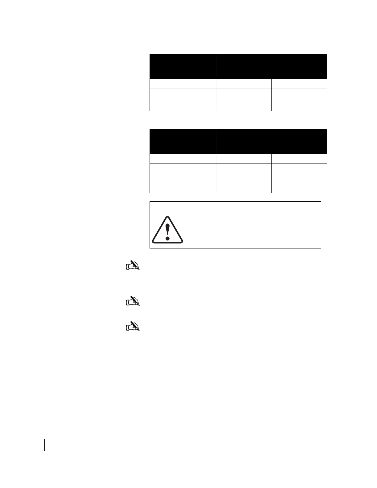
Revision record
Revision Date of issue Scope
Rev 1 6/28/03 Initial release
Rev 2 9/16/03 SBC installation instructions
revised to use 192.168.0.1;
troubleshooting instructions
ported from User Guide
1033294-0001.
Rev 3 03/04/04 Added information on SBC
configuration file.
Rev 4 05/18/04 Added software release 4.2.3
updates and an appendix for
disabling Web browser proxy
server settings.
Rev 5 10/27/04 Added "DW6002" to the document
title. Revised DVADB appendix to
support DW6002. Added a new
appendix for the Fallback Updater
utility.
Rev 6 12/23/04 Updated manual to support new
DC/DC power supply.
Rev A 03/31/06 New Hughes branding
xxii
1033295-0001 Revision A
• About this document
Page 23
Chapter 1
Introduction
This chapter discusses:
• Equipment overview on page 1
• Equipment and cable specifications on page 4
• Installation methods on page 7
• Satellite-based commissioning (SBC) overview on page 8
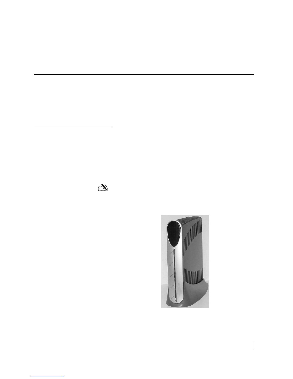
Equipment overview
The DW6000 is designed to provide Internet or corporate Intranet
connectivity via satellite through a single terminal. The receive
and transmit capability is housed in a single chassis as shown in
Figure 1.
The DW6002 is a DW6000 equipped with an internal modem to
support the Virtual Private Network Automatic Dial Backup
(VADB) feature for enterprise customers.
Note: The instructions in this manual apply to both the DW6000
and DW6002; however, only the DW6000 is referenced in the
instructions. The DW6002 is specifically referenced in
Appendix D.
Figure 1: DW6000
Chapter 1 • Introduction
1033295-0001 Revision A
1
Page 24
The DW6000, in combination with an antenna and an Ethernet
hub or wireless base station, provides satellite connectivity for
multiple local area network (LAN) hosts. All the necessary
software resides on the DW6000, which serves as the router.
Because the software is on the DW6000, there is no need for a
computer to run any client software.
The end user or customer must supply and configure all hardware
and software necessary to install and operate a wired (Ethernet)
or wireless LAN.
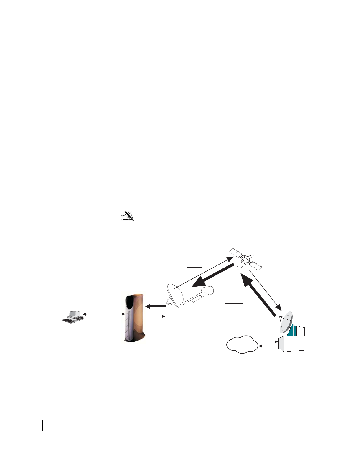
Figure 2 illustrates the functionality of the DW6000 within a
network. The DW6000 is independent of operating platforms. It
can also be used with devices other than computers, such as
point-of-sale (POS) terminals or credit verification devices.
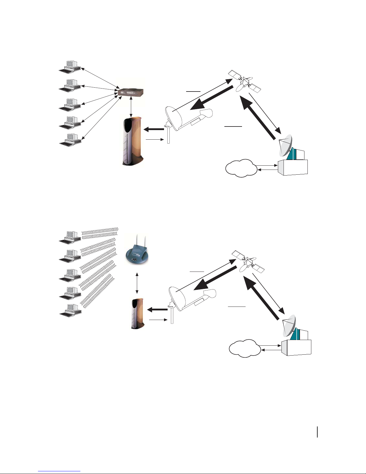
Figure 3 illustrates the functionality of a DW6000 within a wired
local area network (LAN). The Ethernet hub that supports the
LAN is connected to the DW6000.
Figure 4 illustrates the functionality of a DW6000 within a
wireless LAN. The wireless base station that supports the LAN is
connected to the DW6000.
POS Terminal
or other device
Unix
Mac
PC
Linux
G-28342 F
03/17/06
Note: Customers who install networks may need a router rather
than a hub, depending on their service plan.
Satellite
Inroute
(to NOC)
Outroute
(from NOC)
Antenna
DW6000
Internet
Figure 2: Remote site with DW6000 installed, single computer
Network
Operations
Center (NOC)
Chapter 1 • Introduction
2
1033295-0001 Revision A
Page 25
Unix
POS terminal
or other device
Ethernet
hub
Satellite
Inroute
Mac
PC
Linux
Unix
Mac
G-25787 F
08/05/03
POS terminal
or other device
Outroute
Antenna
Gateway
Internet
Figure 3: Remote site with DW6000 installed, wired (Ethernet) LAN
Wireless
base station
Satellite
Inroute
Network
Operations
Center (NOC)
PC
Linux
G-26179 F
08/20/03
Outroute
Antenna
Gateway
Internet
Figure 4: Remote site with DW6000 installed, wireless LAN
Chapter 1 • Introduction
1033295-0001 Revision A
Network
Operations
Center (NOC)
3
Page 26

Equipment and cable
specifications
Table 1 lists DW6000 equipment specifications.
Tables 2 - 4 list cable specifications for RG-6, RG-11, and Heliax
cable. The cable specifications are the same regardless of the type
of antenna used and are determined by the distance from the
DW6000 to the antenna assembly.
Ta b l e 1 : DW6000 Specifications
Product Element Specification
Weight 2.4 lb (1.089 kg)
Width 1.7 in (4.32 cm)
Height 9.5 in (24.13 cm)
Depth 10.5 in (26.67 cm)
AC/DC power supply
Electrical requirements:
• Input line voltage
• Input line frequency
• Rated power
consumption
4.5 in (11.43 cm) with pedestal base
9.75 in (24.77 cm) with pedestal base
PN 1031105-0001 Rev B
100 - 240 V - 2A max
50-60 HZ AC
64 W
Power cord
DC/DC power supply
Electrical requirements:
• Input line voltage
• Rated power
consumption
Power cord
Safe operating temperature range
Safe operating humidity 5% to 95% non-condensing
Safe altitude 10,000 ft.
Cooling method Convection
Por ts • One Ethernet LAN port supporting
Main processor 133 Mhz
Detachable power cord for 110 VAC outlet
type
PN 1033554-0001 Rev B
12.7 - 25 V - 10A max
64 W
Detachable power input cables and
connector
0 to 40 degrees C (above 5000 feet
altitude, reduce maximum temperature by
1 degree C per 1000 feet)
10BaseT or 100BaseT operation, RJ45
switched
• Telephone line port (DW6002 only)
Chapter 1 • Introduction
4
1033295-0001 Revision A
Page 27
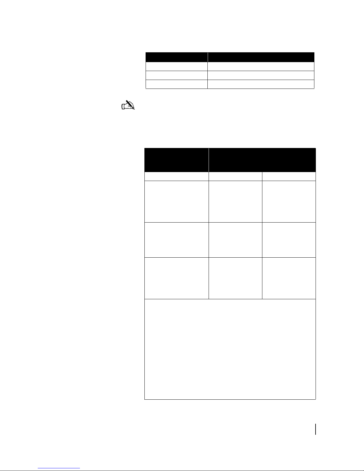
Table 1: DW6000 Specifications
Product Element Specification
Main memory 32MB
Flash memory 8MB
Protocol Support TCP/IP protocol suite
Note: The following cable specifications represent minimum
cable requirements. Failure to meet these requirements may
require you to replace the cables at a later time with cables that
meet the requirements listed in this section.
Tab l e 2 : RG-6 cable specifications
Cable length from
antenna assembly to
Type of cable to be used
computer
Receive Tran smi t
Up to 100 ft. RG-6 with copper
clad steel conductor
(DC resistance of
CommScope 5730
or less)
Up to 300 ft. RG-6 with solid
copper center
conductor
(CommScope 5729
or equivalent)
300 ft. to 420 ft. RG-6 with solid
copper center
conductor and quad
shield (CommScope
5781 or equivalent)
(PN 1029265-0001)
• A higher grade of cable can be used for an installation where a lower
grade is specified. For example, an RG-6 cable with solid copper
center conductor and quad shield can be used for installations where
the cable length is less than 300 ft. Never use a lower grade of cable
than specified. Be sure to record the grade of the cable used for the
installation. The grade is printed on the cable every few feet. Never
use a cable which does not have the manufacturers name and its
grade clearly printed on it!
• The choice of grounding scheme may affect the choice of cable
used. Meeting the National Electrical Code grounding requirements
is easier if you use RG-6 cable with a solid copper center conductor
and quad shield. However, you can also meet the requirements by
using RG-6 cable with a solid copper center conductor or copper
clad steel conductor only and grounding the mast as described in the
appropriate antenna installation manual.
RG-6 with copper
clad steel conductor
(DC resistance of
CommScope 5730
or less (32
ohms/1000 ft.))
RG-6 with solid
copper center
conductor
(CommScope 5729
or equivalent)
RG-6 with solid
copper center
conductor and quad
shield (CommScope
5781 or equivalent)
(PN 1029265-0001)
Chapter 1 • Introduction
1033295-0001 Revision A
5
Page 28
Tab l e 3 : RG-11 cable specifications
Cable length from
antenna assembly to
Type of cable to be used
computer
Receive Tran smi t
Up to 270 ft. RG-11 with copper
clad steel conductor
(CommScope 5916)
Tab l e 4 : Heliax cable specifications
Cable length from
antenna assembly to
Type of cable to be used
computer
Receive Tran smi t
Up to 1370 ft. 1/2-inch Heliax
cable (Andrew
LDF4-75A or
equivalent)
CAUTION
Remember to:
• Install 360° weatherproofing for all connections.
• Install drip loops when needed.
• Install service loops when needed.
RG-11 with copper
clad steel conductor
(CommScope 5916)
1/2-inch Heliax
cable (Andrew
LDF4-75A or
equivalent)
Chapter 1 • Introduction
6
1033295-0001 Revision A
Note: Coaxial cables with copper clad steel center conductors
must have the DC resistance of CommScope 5730 or less (32
ohms/1000 feet). The cable length cannot exceed 100 feet.
Note: Do not use splitters.
Note: Use plenum rated cable only if the cable is to be run in
plenum space which is carrying return air for the air circulation
system, or when local laws require it.
Page 29

Installation methods
There are three ways to install the DW6000:
• Satellite-based commissioning (SBC) is now the preferred
method. All commissioning is done over the satellite
connection. No installer software is required. Assemble and
install the system using the instructions in
Chapter 2 –
Installing the DW6000 using satellite-based commissioning
(SBC).
• If SBC is not available and an analog phone line is available,
use the installer software and your laptop to install and
commission the system. See
Appendix A – Installing the
DW6000 using dial-up commissioning, on page 83.
• If SBC and an analog phone line are not available, use the
Installer Console to install and commission the system. See
Appendix B – Installing the DW6000 using the Installer
Console, on page 113.
CAUTION
Only use the Installer Console to install the DW6000 if
instructed to do so by Hughes.
Note: Sometimes the unit must be configured via the Installer
Console for various reasons. Only units installed for enterprise
customers can be configured via the Installer Console. The
installation specification will note when SBC or dial-up
commissioning is not available. In those cases, follow the
instructions in
Installer Console, on page 113.
Appendix B – Installing the DW6000 using the
Chapter 1 • Introduction
1033295-0001 Revision A
7
Page 30

Satellite-based
commissioning (SBC)
overview
Satellite-based commissioning (SBC) is currently the preferred
commissioning method for registering DW6000 units. The SBC
process is completed via satellite and does not require a dial-up
connection to the registration server.
Note: A dial-up connection to the registration server is required
if SBC is not available.
Procedures to complete SBC are provided in Chapter 2 –
Installing the DW6000 using satellite-based commissioning
(SBC).
SBC configuration file
An SBC configuration file (sbc.cfg) is present in DW6000s that
support SBC. The sbc.cfg file contains satellite information for
SBC and the auto-commissioning server (ACS) to be used during
the commissioning process. Occasionally, new satellites are
activated to support satellite service. As a result, installers might
be required to upload an sbc.cfg file to the DW6000 prior to
installation or manually enter satellite parameters during the
installation process.
If a new satellite is activated, and a new sbc.cfg file is available
for installers, then installers will be instructed to download the
sbc.cfg file from an installation support Web site. The sbc.cfg file
must be saved on the installer laptop prior to commissioning and
then uploaded to the DW6000. Instructions for uploading the
sbc.cfg file to the DW6000 are provided in
configuration file to the DW6000 on page 23.
If a new satellite is activated, and a new sbc.cfg file is not
available, then the new satellite parameters will be distributed to
installers via a technical update e-mail or in an installation
specification. The satellite parameters must be manually entered.
If SBC is not available, the DW6000 system must be installed
using a dial-up connection to the registration server (refer to
Appendix A – Installing the DW6000 using dial-up
commissioning) or manually (refer to Appendix B – Installing the
DW6000 using the Installer Console).
Uploading the SBC
Chapter 1 • Introduction
8
1033295-0001 Revision A
Page 31

Chapter 2
Installing the DW6000 using
satellite-based commissioning (SBC)
This chapter discusses:
• System pre-installation on page 10
• Summary of DW6000 installation process on page 12
• Post-installation tasks on page 13
• DW6000 items required for installation on page 14
• Installing the antenna assembly on page 15
• The power supply on page 16
• Assembling the DW6000 and connecting it to the installer PC
on page 18
• Powering up and reading the DW6000 LED display on
page 21
• Uploading the SBC configuration file to the DW6000 on
page 23
• Commissioning the DW6000 on page 26
• Post-installation tasks on page 40
Chapter 2 • Installing the DW6000 using satellite-based commissioning (SBC)
1033295-0001 Revision A
9
Page 32

System pre-installation
Check to be sure both you and the customer have fulfilled all
system and site requirements before beginning the installation.
Installation PC requirements
Customer installation
requirements
The installer laptop PC must fulfill the following requirements.
• Ethernet enabled network interface card (NIC) and Ethernet
cable.
• Windows 98 SE, Windows ME, Windows 2000, or Windows
XP operating system with DHCP configured to automatically
obtain IP addresses. See
installer laptop for IP addressing, on page 141.
• Internet Explorer 5.5 or 6.0 and that the browser is not using
any proxy settings.
• Customer PC qualification tool disk or CD.
• Dial-out modem if not using satellite-based commissioning
(SBC).
• Installer software installed if not using SBC. See DW6000
items required for installation on page 14.
• The latest version of the satellite-based commissioning
configuration file (sbc.cfg) if instructed to install it.
The customer must provide a computer with:
• Operating system
– PC: Windows 98 SE, Windows Me, Windows 2000,
Windows XP
– MAC: 9.0 - 10.2 (excludes 10.0)
Appendix C – Configuring the
10
• Processor
– PC: Pentium II 333 Mhz or faster
– MAC: 300 Mhz or faster
• Memory
– PC: 64MB RAM, Windows 98SE and Me; 128MB RAM
Windows 2000 and XP.
– MAC: 128MB
• Free hard drive space
– PC: 100MB
– MAC: 150MB
• A functioning 10/100 Ethernet interface installed on at least
one computer. This is needed to ensure the customer can surf
before you leave.
Chapter 2 • Installing the DW6000 using satellite-based commissioning (SBC)
1033295-0001 Revision A
Page 33

• A 6-foot Cat-5 Ethernet cable to connect the DW6000 to the
customer’s computer. If a longer cable is needed, the
customer must supply it. Either crossover or straight-through
Cat-5 Ethernet cable can be used.
• A power strip or surge protector. If one of these is not present,
proceed with the installation using the wall outlet or other
power source.
• An analog phone line if not using SBC.
Note: If the customer wants to connect a network to the
DW6000, he or she must do so via an Ethernet hub or other such
equipment. The customer must supply and configure the hub and
cables. IP address information is provided during commissioning.
Note: Before beginning the installation, confirm your laptop’s
TCP/IP settings are configured to "Obtain an IP address
automatically." See Appendix D – on page 115.
CAUTION
Do not connect the power supply to the DW6000, or connect
the power supply to a power source, before instructed to do
so.
CAUTION
• Do not block any ventilation openings. Do not install near
any heat sources such as radiators, heat registers,
ovens, stoves, or other apparatus (including amplifiers)
that produce heat.
• Recommended ventilation space around the top and
sides of the DW6000 assembly should be approximately 6
inches. Ventilation is necessary to avoid overheating.
Chapter 2 • Installing the DW6000 using satellite-based commissioning (SBC)
1033295-0001 Revision A
11
Page 34

Summary of DW6000
installation process
The DW6000 installation is a 15-step process. Refer to the
appropriate antenna installation manual for those steps involving
antenna installation.
1. Qualify the customer’s PC with the qualification tool.
2. Conduct the site survey.
3. The customer approves the site survey.
4. Assemble the indoor equipment. Assemble the DW6000 and
connect it to the installer laptop. Power up the DW6000 and
laptop and verify connectivity.
5. Compute the pointing coordinates using the SBC interface
installation software.
6. Assemble the antenna. Pre-set the elevation and polarization
values.
7. Mount the satellite antenna.
8. Run cables and ground the system. Clearly label the receive
and transmit coaxial cables at the antenna, ground block, and
indoor unit connectors.
9. Receive point the antenna using the SBC interface.
10. Auto cross pol the antenna. When the antenna is locked in
place and continues to pass isolation, finish weather sealing
the coaxial cable connections.
11. Register the DW6000 using SBC. The customer supplies a
SAN and Personal Identification Number (PIN) and clicks
to agree to subscriber agreement.
12. Verify the DW6000 has finished downloading its software
and connect it to the customer’s PC. The customer checks
that TCP/IP settings are set to obtain an IP address
automatically and restarts the computer.
12
Note: It is recommended that the DW6000 be protected by a
surge protector. Power surges are very common and a major cause
of failure of electronic devices.
13. The customer verifies connectivity by accessing a Web site.
14. Record the DW6000 site ID and assigned IP address(es) for
the customer on the Quick Start Guide. Clean up trash and
verify connections are weather proofed. Optional: assist in
customer computer configuration.
15. Complete FSO within 24 hours.
Chapter 2 • Installing the DW6000 using satellite-based commissioning (SBC)
1033295-0001 Revision A
Page 35

Post-installation tasks
The following tasks must be completed after installing the
DW6000 and prior to leaving the customer’s site:
• Confirm “All files are up-to-date” appears in the Software
Download Status
field on the System Control Center’s
System Status page.
• Use the customer’s computer to access an Internet site after
confirming “All files are up-to-date” appears in the
Download Status
field on the System Control Center’s
Software
System Status page.
• Print the customer’s System Information page and record
the DW6000’s site ID, Gateway ID, and subnet mask on the
Quick Start Guide. Help the customer create a browser
shortcut to the System Control Center. If necessary, rename
the shortcut "System Control Center."
Chapter 2 • Installing the DW6000 using satellite-based commissioning (SBC)
1033295-0001 Revision A
13
Page 36

DW6000 items required
for installation
You need all the items shown in Figure 5 to install the DW6000.
The DW6000 installation kit includes the Ethernet cable,
DW6000, power supply and cords, pedestal base, and Quick Start
Guide. The antenna assembly is shipped in a separate box.
The installation specification, work order, PC qualification tool,
and SBC.cfg file will be provided to you.
Note: The DW6002 installation kit does not include the Ethernet
cable.
Note: The DC/DC power supply (PN 1033554-0001) is not
shown in
have DC power sources.
Figure 5. This power supply is required for sites that
Quick Start
Guide
Ethernet cable
DC cord
Qualifying the customer’s
PC with the qualification
tool
PC qualification tool
HUGHES
AC cord
POWER
Power supply
DW 6000
Installation
Specification
SBC.cfg file
(if instructed to upload it)
or work
Pedestal
base
order
Figure 5: Items required for installation
Insert the disk containing the customer PC qualification tool in
the customer computer. Run all the checks in the tool to ensure
the customer’s computer is set up to work with the DW6000.
The tool does not function on a computer operating with a
MacIntosh, Linux, or Unix operating system.
14
1033295-0001 Revision A
Chapter 2 • Installing the DW6000 using satellite-based commissioning (SBC)
Page 37

Installing the antenna
assembly
The DW6000 can be used with the Hughes 74cm Two-Way
antenna. The DW6000 can also be used with .98, 1.2, and 1.8m
antennas.
Use the appropriate antenna installation manual to assemble and
install the satellite antenna. Attach the coaxial cables to the
DW6000 Satellite In and Satellite Out connectors. You must
clearly label the receive and transmit cables. Because the entire
commissioning process will be done over the satellite, the receive
and transmit cables must be connected from the satellite antenna
to the DW6000.
Refer to Related publications on page xxi in the About section of
this manual for a list of antenna installation manuals. Follow all
safety procedures.
CAUTION
• The two-way satellite dish must be installed in a location
or manner not readily accessible to children and so that
the dish bottom is at least 5 feet above ground level.
• Professional installation or service of the two-way
satellite dish is required by the Federal
Communications Commission because the radio
transmits radio frequency energy.
• This device emits radio frequency energy when in
transmit mode. To avoid injury, do not place head or
other body parts between the feed horn and satellite
dish when the system is operational.
• Unplug the indoor power connection before performing
maintenance or adding upgrades to any satellite dish
components.
• Do not allow anything to come in contact with the front
surface of the satellite dish.
Chapter 2 • Installing the DW6000 using satellite-based commissioning (SBC)
1033295-0001 Revision A
15
Page 38

The power supply
There are two power supplies available for use with the DW6000:
• AC/DC power supply (part number 1031105-0001, model
ADP-0641-M2)
• DC/DC power supply (part number 1033554-0001, model
DC-0651-M3)
Always use the power supply provided with the DW6000 system.
The power supply part number is listed on a sticker that is
attached to the power supply. Refer to the sticker to verify you
have the correct power supply.
Note: In this manual, only the AC/DC power supply is shown in
graphics depicting power supply connections.
CAUTION
• This unit’s performance may suffer if the wrong power
supply is used.
• NEVER pull the DC power cord from the back of the
DW6000. Doing so could damage the pins and also
cause a short in the system.
• When power needs to be removed from a DW6000 that
uses an AC/DC power supply, ALWAYS unplug the AC
power cord from the wall outlet, surge protector, or
power strip.
• When power needs to be removed from a DW6000 that
uses a DC/DC power supply, ALWAYS unplug the DC
input cable connector from the power supply.
• Power supply with the part number 1031105-0001 is to
be used only in the United States and Canada.
• AC/DC power supplies must be used with 110-volt AC
input.
• If the DW6000 will be installed outside the United States
and Canada, always observe the power standards and
requirements of the country where it will be installed.
16
Chapter 2 • Installing the DW6000 using satellite-based commissioning (SBC)
1033295-0001 Revision A
Page 39

AC/DC power supply
The power supply most commonly used is the AC/DC power
supply shown in
Figure 6. This power supply supports AC input
power.
Figure 6: AC/DC power supply
DC/DC power supply
The DC/DC power supply (Hughes part number 1033554-0001)
shown in
Figure 7 supports DC input power. The power supply is
shipped in a kit (Hughes kit part number 1036088-0001) that also
contains a DC input cable kit. The cable kit contains an input
power connector, connector pins, and a wiring diagram; the kit
does not contain wire.
Refer to the wiring diagram to assemble the DC input power
cable.
Note: The installer must provide the wire required to assemble
the DC input power cable.
Chapter 2 • Installing the DW6000 using satellite-based commissioning (SBC)
Figure 7: DC/DC power supply
1033295-0001 Revision A
17
Page 40

Note: Some installation and troubleshooting steps require you to
power-cycle the DW6000. When power-cycling a DW6000 that
uses an AC/DC power supply, always disconnect the AC power
cord from the power source. When power-cycling a DW6000 that
uses a DC/DC power supply, always disconnect the DC input cable
connector from the power supply.
Assembling the DW6000
and connecting it to the
installer PC
1. Take the pedestal base in one hand and the DW6000 in the
other. Orient them
as shown in Figure 8. The Power LED will
be at the bottom.
2. The DW6000 has two curved ridges, one on each side of its
opening.
See Figure 9. The pedestal base has six guides that
slide along these ridges. See Figure 10. Locate the ridges and
the two guides at the front of the pedestal base.
3. Align the guides with the ridges.
4. Gently slide the guides along the ridges until the DW6000
clicks into place.
Note: If you need to remove the DW6000 from the pedestal
base, pull up and back on the clip on the back of the base.
Figure 11. You can then slide the base off the DW6000.
See
18
Chapter 2 • Installing the DW6000 using satellite-based commissioning (SBC)
1033295-0001 Revision A
Figure 8: Orienting pedestal base and DW6000
Page 41

Figure 9: DW6000 ridges
Figure 10: Two front guides
Chapter 2 • Installing the DW6000 using satellite-based commissioning (SBC)
Figure 11: Pedestal base clip
1033295-0001 Revision A
19
Page 42

5. Connect the installer PC to the DW6000 with an Ethernet
cable. See
Figure 12.
6. Connect the power supply’s DC power cord to the DC IN port
on the DW6000. See
Figure 12.
7. Connect the AC power cord to the power supply and power
strip or surge protector. See
Figure 12.
Connect the input power cable to the power supply if the
DW6000 has a DC/DC power supply.
20
Chapter 2 • Installing the DW6000 using satellite-based commissioning (SBC)
1033295-0001 Revision A
Figure 12: Connecting component interconnection cables
Page 43

Powering up and
reading the DW6000
LED display
If the DW6000 for your installation uses an AC/DC power
supply, and the power supply’s AC power cord is connected to a
power strip or surge protector, connect the power strip or surge
protector to a 110 V wall outlet or other AC power source.
The DW6000 LEDs will come on in the following order:
1. Power LED comes on solid to indicate the DW6000 is
powered up.
2. LAN LED comes on within 30 seconds to indicate LAN
connectivity is detected.
3. Power LED blinks, indicating the unit is not commissioned
and therefore is running fallback.bin and not main.bin.
Note: In countries outside North America, the DW6000 may be
plugged, with a physical adapter, directly into a 220 V outlet.
Different countries may have different standards and requirements.
Note: Whenever the LEDs do not function properly as described
in this section, make sure you have the correct power supply. Refer
to
page 16 for more information on power supplies.
Obtaining the IP address
and testing the Ethernet
connection
1. Restart the installer PC so it obtains an IP address from the
DW6000. Or type
line prompt.
2. The embedded DHCP server assigns IP address 192.168.0.2
to the installer PC. The default Gateway address is set to
192.168.0.1.
Properties screen. (These may vary among different Windows
operating systems.)
3. Type Ping 192.168.0.1 at the DOS prompt and press
E
NTER. Figure 14 shows a successful ping attempt; Figure 15
shows an unsuccessful attempt. If the computer fails to ping
the DW6000, check that you installed the NIC properly and
followed the instructions in
installer laptop for IP addressing, on page 141.
If the NIC is installed properly and TCP/IP is configured
correctly, check that all the cable connections are secure. If
they are, unplug the DW6000 from the surge protector or
other power source; shut down and power off the computer;
plug the DW6000 back in, and turn the computer back on.
Then try the ping test again. If it is unsuccessful, call installer
support for assistance.
ipconfig /renew at a DOS command
Figure 13 shows a sample Windows TCP/IP
Appendix C – Configuring the
Chapter 2 • Installing the DW6000 using satellite-based commissioning (SBC)
1033295-0001 Revision A
21
Page 44

Figure 13: TCP/IP Properties screen
22
Figure 14: Successful ping
Figure 15: Failed ping
Chapter 2 • Installing the DW6000 using satellite-based commissioning (SBC)
1033295-0001 Revision A
Page 45

Uploading the SBC
configuration file to the
DW6000
The instructions in this section must be completed if you were
provided with an SBC configuration file (sbc.cfg) or if you were
instructed to download an sbc.cfg file from an installation support
Web sit e .
The sbc.cfg file contains satellite information for SBC and the
auto-commissioning server (ACS) to be used for the
commissioning process. The sbc.cfg file must be saved on the
installer laptop prior to commissioning; the file is then uploaded
to the DW6000.
Follow the steps below to upload an sbc.cfg file to the DW6000.
Skip to Commissioning the DW6000 on page 26 if you do not
have to upload an sbc.cfg file to the DW6000.
1. Open a browser on the installer laptop.
2. Type http://192.168.0.1/fs/advanced/
advanced.html in the address bar and press ENTER.
The Advanced page shown in Figure 16 appears.
Chapter 2 • Installing the DW6000 using satellite-based commissioning (SBC)
Figure 16: Advanced page
1033295-0001 Revision A
23
Page 46

3. Click Setup at the bottom of the left pane on the Advanced
page. The Setup screen shown in
Figure 17 appears.
The Setup link is circled in Figure 16.
4. Click Config File Upload. The Configuration File Upload
screen shown in
Figure 18 appears.
Figure 17: Setup screen
Figure 18: Configuration File Upload screen
24
Chapter 2 • Installing the DW6000 using satellite-based commissioning (SBC)
1033295-0001 Revision A
Page 47

5. Click Browse.
The Choose File screen shown in Figure 19 appears.
6. Navigate to the location on the installer PC where the sbc.cfg
file is saved.
7. Select the file and click Open. See Figure 19.
Figure 19: Locating the sbc.cfg file
8. Click Upload.
The screen shown in Figure 20 appears indicating the sbc.cfg
file was successfully uploaded to the DW6000.
9. Click Close to return to the Setup screen.
Figure 20: Confirming sbc.cfg file upload to the DW6000
Chapter 2 • Installing the DW6000 using satellite-based commissioning (SBC)
1033295-0001 Revision A
25
Page 48

Commissioning the
DW6000
Follow these steps to commission the DW6000:
1. Open a browser on the installer laptop.
2. Type http://192.168.0.1/fs/advanced/
advanced.html in the address bar and press ENTER. The
Advanced page appears.
3. Click Setup at the bottom of the left pane on the page.
The Setup screen appears. See Figure 21.
26
Figure 21: Initial registration screen
Chapter 2 • Installing the DW6000 using satellite-based commissioning (SBC)
1033295-0001 Revision A
Page 49

4. Click Registration - Installer.
The Antenna Location screen appears. See Figure 22.
Figure 22: Antenna location
5. Enter the ZIP code of the location where you are installing
the DW6000 and click Next.
The location where the DW6000 will be installed may also be
entered manually. Follow steps
a through c below if you wish
to enter the antenna location manually.
a. Select the Enter Location Manually check box on the
Antenna Location screen shown in
Figure 22.
b. Enter the longitude and latitude for your location on the
Manual Entry of Antenna Location screen shown in
Figure 23.
c. Click Next.
Refer to Appendix H – Lat/Long Decimals to Minutes Table,
on page 177 to determine latitude and longitude decimal to
minutes conversion.
The Verification of Antenna Location screen appears. See
Figure 24.
Chapter 2 • Installing the DW6000 using satellite-based commissioning (SBC)
1033295-0001 Revision A
27
Page 50

Figure 23: Entering location manually
28
Chapter 2 • Installing the DW6000 using satellite-based commissioning (SBC)
1033295-0001 Revision A
Figure 24: Verifying antenna location
Page 51

6. Verify the information displayed on the Verification of
Antenna Location screen is correct.
7. Click Next.
The Satellite Parameters screen appears. See Figure 25.
8. Click on the
Satellite Transponders
drop-down menu on the
Satellite Parameters screen and select the satellite and
transponder listed on the work order or in the installation
specification. Click Next.
If the satellite and transponder for your installation are not
listed in the drop-down menu, and you were not provided
with an SBC configuration file (sbc.cfg), then you must
complete steps
a - d below to manually enter satellite
parameters. The satellite parameters should have been
provided to you in a technical update e-mail or in an
installation specification.
a. Select the Enter satellite parameters manually check box
on the Satellite Parameters screen shown in
Figure 25.
b. Click Next.
The Manual Entry of Satellite Parameters screen appears.
See
Figure 26.
c. Enter or select the appropriate values for the following
fields:
• Longitude
• Hemisphere
• Frequency
•Symbol rate
• Receive polarization
• Transmit polarization
• 22KHz tone
• Viterbi Mode
• Enable OPI Display
Chapter 2 • Installing the DW6000 using satellite-based commissioning (SBC)
d. Click Next.
The Verification of Satellite Parameters screen appears. See
Figure 27.
Note: The Enable OPI Display box must be selected on the
Verification of Satellite Parameters screen if an OPI is used to
point the antenna.
1033295-0001 Revision A
29
Page 52

Figure 25: Selecting the satellite and transponder
30
Chapter 2 • Installing the DW6000 using satellite-based commissioning (SBC)
1033295-0001 Revision A
Figure 26: Entering satellite parameters manually
Page 53

Figure 27: Verifying satellite parameters
9. Verify the information on the Verification of Satellite
Parameters screen is correct and click Next.
The Receive Antenna Pointing screen appears. See Figure 28.
Chapter 2 • Installing the DW6000 using satellite-based commissioning (SBC)
Figure 28: Receive pointing
1033295-0001 Revision A
31
Page 54

10. Click Display Signal Strength to view the signal quality
factor (SQF). See
Note: The Signal Quality window may not appear on top.
Just minimize the other windows until you can see it.
Figure 29.
When the signal is locked, a check mark appears in the
Perform ACP checkbox shown in Figure 28.
Figure 29: Receive pointing results
11. Peak the receive pointing as instructed in the antenna
installation manual.
You must peak the signal even if the antenna is locked to it.
12. Click Close to close the Signal Quality window. See
Figure 29.
13. Click Next.
The Transmit Antenna Pointing screen appears. See
Figure 30.
32
Chapter 2 • Installing the DW6000 using satellite-based commissioning (SBC)
1033295-0001 Revision A
Page 55

Figure 30: Cross Pol
14. Click Manual to initiate the manual cross-pol test.
15. Click Continue on the Warning pop-up that appears. See
Figure 31.
Chapter 2 • Installing the DW6000 using satellite-based commissioning (SBC)
Figure 31: Manual cross-pol warning message
1033295-0001 Revision A
33
Page 56

The test status, isolation value, and the pass/fail result are
displayed in the Cross Pol Test window.
Figure 32: Manual cross-pol test results
Note: The manual cross-pol test will time-out 5 minutes after
clicking on the Manual button. Make sure any antenna adjustments
required to achieve maximum transmit isolation are completed
within this time frame.
See Figure 32.
16. Adjust the antenna during the manual cross-pol test to
achieve maximum transmit isolation.
17. Bolt down the antenna when the unit consistently passes the
manual cross-pol test.
18. Click Close to close the Cross Pol Test window.
19. Click Automatic on the Transmit Antenna Pointing screen to
initiate the automatic cross-pol (ACP) test.
Re-peak the transmit isolation in manual mode if the unit
does not pass the ACP test.
34
20. Click Close to close the Cross Pol Test Window if the unit
passes the ACP test.
21. Click Next on the Transmit Antenna Pointing screen if the
unit passed the automatic cross-pol test.
22. Select a registration server from the drop-down menu on the
Registration Server Selection screen. See
the installation specification or work order if you are unsure
which server to select.
You may also access the registration server by manually
entering its address. Follow these steps if you must manually
enter the registration server’s address:
a. Select the Enter Registration Server address manually
check box.
b. Enter the registration server’s address in the HTTP:// field.
c. Select the Secure HTTP Mode check box to enable a
secure connection to the registration server.
Chapter 2 • Installing the DW6000 using satellite-based commissioning (SBC)
1033295-0001 Revision A
Figure 33. Refer to
Page 57

Figure 33: Selecting the registration server
23. Click Next.
The Registration In Progress screen appears. See Figure 34.
The following status messages appear on the Registration In
Progress screen:
• A satellite connection is being established.
• The encryption keys are being downloaded.
• The remote is being authenticated.
Chapter 2 • Installing the DW6000 using satellite-based commissioning (SBC)
1033295-0001 Revision A
35
Page 58

Figure 34: Registration in progress
24. Click Next after the actions indicated in the status messages
have been completed.
A screen appears stating you will be redirected to a secure
connection.
See Figure 35.
25. Click OK.
Figure 35: Secure connection
36
Chapter 2 • Installing the DW6000 using satellite-based commissioning (SBC)
1033295-0001 Revision A
Page 59

Note: The screens displayed during the registration process
may vary from the screens shown on the following pages.
The screens displayed during registration typically depend
on the customer type.
26. Ask the customer to enter their SAN and PIN on the
Registration screen shown in
Figure 36.
27. Click Continue.
Figure 36: Entering SAN and PIN
28. When registration is complete, click Next.
The Registration information screen shown in Figure 37
appears.
Chapter 2 • Installing the DW6000 using satellite-based commissioning (SBC)
1033295-0001 Revision A
37
Page 60

Figure 37: Registration information (to be recorded on Quick
Start Guide)
29. Click Continue.
A message appears indicating the remote will download the
parameters. This message will be followed by another
message indicating the remote is being configured for
operation.
A Registration Complete screen appears. See Figure 38.
38
Chapter 2 • Installing the DW6000 using satellite-based commissioning (SBC)
1033295-0001 Revision A
Page 61

Figure 38: Registration complete - restart
30. Click Restart.
A Terminal Reset window appears. See Figure 39.
Chapter 2 • Installing the DW6000 using satellite-based commissioning (SBC)
Figure 39: Close for terminal reset
31. Click Close. The DW6000 will reset. The unit is now
commissioned.
1033295-0001 Revision A
39
Page 62

Post-installation tasks
Complete the following tasks after installing the DW6000 and
before leaving the customer’s site:
• Confirm “All files are up-to-date” appears in the Software
Download Status
field on the System Control Center’s
System Status page.
• Use the customer’s computer to access an Internet site after
confirming “All files are up-to-date” appears in the
Download Status
field on the System Control Center’s
Software
System Status page.
• Print the customer’s System Information page and record
the DW6000’s site ID, Gateway ID, and subnet mask on the
Quick Start Guide. Help the customer create a browser
shortcut to the System Control Center. If necessary, rename
the shortcut "System Control Center."
• Help the customer download the DW6000 User Guide.
Confirming all files
up-to-date
1. Type 192.168.0.1 in the browser’s location or address bar and
press E
NTER. The System Control Center shown in Figure 40
appears.
2. Click System Status. The System Status page appears. See
Figure 41.
3. Check the Software Download Status line message. If it reads
"All files are up-to-date," the unit has been commissioned.
If "All files up-to-date" does not appear, wait a few minutes.
If the message still does not appear, power cycle the unit by
unplugging it from the power source and plugging it back in
and waiting 15 minutes. If the message still does not appear,
contact installer support.
40
Chapter 2 • Installing the DW6000 using satellite-based commissioning (SBC)
1033295-0001 Revision A
Page 63

Figure 40: System Control Center
Figure 41: System Status page
Chapter 2 • Installing the DW6000 using satellite-based commissioning (SBC)
1033295-0001 Revision A
41
Page 64

Connecting the DW6000 to
the customer’s computer
Connect the customer’s computer to the DW6000 with an
Ethernet cable.
See Figure 42. Make sure the customer can
browse to the Hughes Web site. If the customer cannot browse,
see the instructions below.
If the customer cannot browse
Configure the installer laptop so its network properties match
those of the customer’s PC. Refer to Appendix D for detailed
instructions for setting network properties. Then:
1. Connect the installer laptop to the DW6000 with an Ethernet
cable.
2. Open a Web browser on the installer laptop.
3. Enter the DW6000 IP address 192.168.0.1 in the browser
URL location bar and press E
NTER. If the DW6000 is
functioning, the System Control Center appears.
4. Enter 192.168.0.1 in the browser URL location bar and press
E
NTER. If the site appears, the DW6000 is functioning. The
customer should refer to the contact information on the
System Control Center’s Help page to get technical support.
Ethernet
Ethernet
cable
42
AC power
cord
Power
supply
DC power
cord
Receive cable
(Satellite In)
Transmit cable
(Satellite Out)
Figure 42: Final configuration
Chapter 2 • Installing the DW6000 using satellite-based commissioning (SBC)
1033295-0001 Revision A
Page 65

Printing the System
Information page
1. Have the customer access the System Control Center by
typing 192.168.0.1 in a Web browser location bar and
pressing E
NTER. The System Control Center in Figure 40
appears.
2. Click System Info. The System Information page appears.
See Figure 43.
3. Have the customer print the page. If they do not have a printer
then they can use Alt/Print Scrn to capture it and paste it into
a word processing, Microsoft Paint, or similar file and save
that.
4. If you have not already done so, record the Site ID, Gateway
address, and subnet mask on the Quick Start Guide.
Chapter 2 • Installing the DW6000 using satellite-based commissioning (SBC)
Figure 43: System Information
1033295-0001 Revision A
43
Page 66

Creating a shortcut to the
System Control Center
Left-click on the
browser icon and drag
it to the desktop.
1. Enter 192.168.0.1 in the browser URL location bar and press
E
NTER to access the System Control Center. See Figure 44.
Reduce the size of the System Control Center window so that
the desktop is visible behind the System Control Center
window.
2. Left-click on the browser icon in the upper left-hand corner
of the browser window and drag it to the desktop.
3. Let go of the mouse button.
A DW6000 System Control Center icon appears. You may
need to rename the icon.
Figure 44: Creating a shortcut on the desktop to the System Control Center
44
Chapter 2 • Installing the DW6000 using satellite-based commissioning (SBC)
1033295-0001 Revision A
Page 67

Chapter 3
The System Control Center
This chapter discusses:
• System Control Center overview on page 46
• Accessing the System Control Center on page 47
• The Home page on page 49
• System Status page on page 51
• Reception Information page on page 52
• Transmission Information page on page 56
• System Information page on page 61
• The Connectivity Test Link on page 62
• The Help menu on page 64
• Advanced pages on page 65
Chapter 3 • The System Control Center
1033295-0001 Revision A
45
Page 68

System Control Center
overview
The DW6000 has an internal Web server that supports the System
Control Center. The System Control Center provides information
about system status, system configuration, and online
documentation. Access it if the DW6000 does not seem to be
functioning properly, to find system information for configuring
networks, or to check system performance.
Note: Each DW6000’s software is updated periodically via
satellite link. Always refer to System Control Center Help and the
latest version of this manual for the latest information about the
System Control Center and DW6000 software.
If at any time you are unable to access the System Control Center,
take the steps below. See
Chapter 4 – DW6000 LEDs and
troubleshooting, on page 67 for more information.
• Make sure the DW6000 is powered up. The Power and LAN
LEDs should be lit solid. (The LAN LED may blink if there
is LAN port activity.) If they are not, power cycle the
DW6000 by unplugging the power cord from the power
source, waiting 10 seconds, and plugging it back in.
• If the System Control Center is still not accessible, check the
Ethernet cable connection from the computer to the DW6000.
Check that the power adapter is securely attached to the
DW6000. Also check the computer’s network configuration.
• If the System Control Center is still not available, try pinging
the unit by entering
command line. If the ping results show
power cycle the unit.
out
ping 192.168.0.1 at a DOS
request timed
• If the ping results show Reply but from... , check the
browser settings. Make sure the browser is not using any
proxy settings.
• If the System Control Center is still not available, contact
installer support.
46
Chapter 3 • The System Control Center
1033295-0001 Revision A
Page 69

Accessing the System
Control Center
The System Control Center is accessed through any browser, such
as Internet Explorer or Netscape. Follow the steps below to set up
an entry for the System Control Center in a browser. The steps are
written for Internet Explorer or Netscape, but you can use a
similar procedure for any browser.
1. Go to
2. Place the cursor in the Internet Explorer Address bar or the
3. Type http://192.168.0.1.
4. Press ENTER. The System Control Center appears. See
Start→ Programs→ Internet Explorer
The browser interface appears.
Netscape Location Bar.
Figure 45.
(or Netscape).
Figure 45: System Control Center Home page
Chapter 3 • The System Control Center
1033295-0001 Revision A
47
Page 70

If the System Control Center
is not accessible
If the IP address also does not work, check that your computer is
configured to obtain IP addresses automatically. If not, follow the
instructions in
Appendix C – Configuring the installer laptop for
IP addressing to configure your computer to obtain an IP address
automatically. Restart the computer and try accessing the System
Control Center again.
If you cannot access the System Control Center through a
browser, follow the instructions below.
1. First try to ping the DW6000 to confirm it is connected to the
network and functioning. Open the Run dialog box by
selecting
Start→
Run.
Type Command and click OK.
2. Type ping 192.168.0.1. Press Enter.
3. If the client fails to ping the host, (that is, if the computer fails
to ping the DW6000), the computer will report that no
packets were received. There are issues with either the
network hardware or configuration. Check the LAN
connections, try restarting the computer, refer to the
instructions that were provided with the network hardware,
and retry the ping test.
48
Chapter 3 • The System Control Center
1033295-0001 Revision A
Figure 46: Failed ping
Figure 47: Successful ping
Page 71

The Home page
The System Control Center Home page has system indicators and
links to DW6000 features and important information regarding
the operation of your DW6000.
System indicators
The system indicators appear at the top of the Home page. The
system indicators are described below and are shown in
Figure 48.
Note: The System Status indicator may be red or green while
other indicators are always blue.
• System Status provides access to the System Status page.
The System Status page displays general system status
information such as signal strength and commissioning
status.
See System Status page on page 51.
If the indicator is green and OK appears below it as shown in
Figure 48, the satellite connection is operating properly.
If the indicator is red and Problem appears below it as shown
in
Figure 49, there is a problem with satellite connectivity.
Click on the indicator to access the System Status page to
view problem details.
• Reception Info provides access to the Reception Information
page. The Reception Information page displays DW6000
receive data.
See Reception Information page on page 52.
• Transmission Info provides access to the Transmission
Information page. The Transmission Information page
displays DW6000 transmit data.
See Transmission
Information page on page 56.
• System Info provides access to the System Information page.
The System Information page displays system information
such as the DW6000 IP address, Site Account Number
(SAN), and the site ID.
See System Information page on
page 61.
Figure 48: System indicators
Figure 49: System Status indicator reporting a problem
Chapter 3 • The System Control Center
1033295-0001 Revision A
49
Page 72

Links
The System Control Center Home page has four groups of links:
• System Status
• Connectivity Test
• Help
• myHughesNet
System Status
Connectivity Test
Help
The following links provide access to system status information:
• View System Status provides access to the System Status
page. The System Status page displays general system status
information such as signal strength and commissioning
status.
page 51.
For more information, see System Status page on
• View Receive Information provides access to the Reception
Information page. The Reception Information page displays
DW6000 receive data.
For more information, see Reception
Information page on page 52.
• View Transmission Information provides access to the
Transmission Information page. The Transmission
Information page displays DW6000 transmit data.
For more
information, see Transmission Information page on page 56.
The Go to Connectivity Test link provides access to the
Connectivity Test page, which can be used to test the connection
between your DW6000 and the Network Operations Center
(NOC).
See The Connectivity Test Link on page 62.
The following links provide access to help-related information:
• Getting Started explains how the DW6000 works and
provides access to DW6000 operating instructions and
recommended settings.
• Browsing Optimization Utility provides access to a utility
that enhances Web browsing performance. The utility has no
effect on download and upload speeds.
• View Help Topics provides access to the Help page. Refer to
the Help page for a variety of help topics ranging from an
overview of the DW6000 to answers to frequently asked
questions.
For more information, see The Help menu on
page 64.
• Contact Information provides access to technical support
information. Contact information may vary by service plan.
50
Chapter 3 • The System Control Center
1033295-0001 Revision A
Page 73

System Status page
The System Status page displays the fields described below.
• Signal Strength - receive signal strength.
• Transmit Status - indicates whether the transmit data path is
operational. Clicking on the status message displays
corresponding help information.
• Receive Status - indicates if the receive data path is
operational. Clicking on the status message displays
corresponding help information.
• Software Download Status - indicates whether DW6000
software and configuration is up-to-date.
• Commission Status - indicates if the unit is commissioned.
• TCP Acceleration Status - indicates if TCP Acceleration is
operational. TCP acceleration provides the expected
performance on a DW6000.
• Web Acceleration Status - indicates if Web Acceleration is
operational. Web Acceleration is operational if you are
browsing HTTP-based Web sites. Web Acceleration may be
inactive if you are browsing on a secure HTTP site (https).
Figure 50: System Status page
Chapter 3 • The System Control Center
1033295-0001 Revision A
51
Page 74

Reception Information
page
The Reception Information page displays the fields described
below.
• Receive status - reports the status of the receive data path.
Clicking on the blue status message displays corresponding
help information.
• Frames received- reports the number of data messages
received by the DW6000 over the satellite link.
• Frames with Errors- reports the percentage of received frames
that were found to be corrupted. A continuously increasing
value indicates problems in the receive path. This may
happen in adverse weather conditions or if there is a problem
with the receive cable or the antenna. However, if a low
non-increasing value is displayed and the system is
functioning, there is no reason for concern. You do not need
to do any troubleshooting or contact installer support.
• Bad Key Frames- indicates the percentage of received frames
that could not be decrypted successfully. All data received
over the satellite is encrypted. A continuously increasing
value indicates the unit is not commissioned.
Table 5 describes the RxCodes in detail.
52
Chapter 3 • The System Control Center
1033295-0001 Revision A
Figure 51: Reception info
Page 75

Receive Status messages
Tab l e 5 : Receive code (RxCode) messages and corrective actions
The following messages may appear in the Receive Status field.
The Comments section in
Table 5 gives more information about
each code and describes any possible corrective measures. See
Figure 52 on page 55 for corrective measure involving cables or
the power supply. Power cycling means unplugging the power
cord from the power source, waiting 10 seconds, and plugging it
back in. If corrective measures do not solve a problem, contact
installer support.
RxCode 5 means receive is working properly. It is the code you
will see most of the time.
Numeric
RxCode
1 The receiver is in pointing mode This condition indicates the installer is
2 The receiver is in factory or NOC mode This status is for DW6000 testing purposes only.
3 The receiver is not locked to a signal If the DW6000 had been operating previously,
Message Displayed Comments
performing antenna pointing. In this mode, the
transmitter is disabled for safety reasons since
the installer is working near the dish. If this
occurs during normal operation, try
power-cycling the DW6000 by unplugging the
power cord from the power source and then
plugging it back in.
You should never see it. If this occurs during
normal operation, try power-cycling the
DW6000 by unplugging the power cord from the
power source and then plugging it back in.
this status is probably due to inclement weather
conditions and will be corrected when the
weather improves. This condition can also
indicate that the unit is unable to receive the
signal from the NOC. This is also associated
with a signal level less than 30. This occurs if
there is a weather outage at the user location, a
NOC outage due to inclement weather or other
reasons, a misaligned or faulty antenna, or
faulty cabling. If this keeps happening under
normal weather conditions, make sure the
power supply is correct. The power supply
should be Part # 1031105-0001. If the power
supply is correct, try power-cycling the DW6000
by unplugging the power cord from the power
source and then plugging it back in.
Chapter 3 • The System Control Center
1033295-0001 Revision A
53
Page 76

Table 5: Receive code (RxCode) messages and corrective actions
4 The receiver is locked to the wrong network This condition should only be seen during
installation and occurs when the receiver is
locked to an incorrect Hughes satellite. This
could also happen if the installer enters
incorrect information during manual pointing. If
this occurs during normal operation, it may be
due to the user changing satellite parameters,
or the antenna becoming misaligned. Make
sure the antenna is aimed at the correct satellite
and verify the correct satellite parameters were
entered or selected during the registration
process.
5 The receiver is operational This is the normal operating state where the
receiver is receiving data from the NOC. Only
when the receiver is in this state will the
transmitter operate correctly.
6 The receiver is not detecting a signal This condition occurs when the unit is not
detecting any type of radio signal from the
antenna. This could indicate that the cabling
between the receiver and the antenna is faulty
or that the receiver itself is faulty. Check that the
cables are firmly connected on the DW6000.
Also, make sure that the power supply is
correct. The power supply should be Part #
1031105-0001. Try power-cycling the DW6000
by unplugging the power cord from the power
source and then plugging it back in.
7 The receiver is locked to an unknown
network
This condition should only be seen during
installation and occurs when the receiver is
locked to a non-Hughes satellite. In rare cases it
may be due to a transient outage at the NOC. If
this occurs during pointing or commissioning,
the antenna has not been pointed correctly. If it
occurs during normal operation, it may be due
to the user changing satellite parameters, or the
antenna becoming misaligned. The former
condition can be corrected by re-commissioning
the site. The latter requires an antenna
repointing.
54
1033295-0001 Revision A
Chapter 3 • The System Control Center
Page 77

G-26
112C07/2
8/03
Ethernet
Ethernet
cable
AC power
cord
Power
supply
DC power
cord
Receive cable
(Satellite In)
Transmit cable
(Satellite Out)
Figure 52: DW6000 connections
CAUTION
Never unplug the DC power cord from the DW6000 while it is powered
on. If the DW6000 uses an AC/DC power supply, always disconnect
the AC power cord from the power strip, wall outlet, or surge
protector. If the DW6000 uses a DC/DC power supply, always
disconnect the DC input cable connector from the power supply.
Chapter 3 • The System Control Center
1033295-0001 Revision A
55
Page 78

Transmission
Information page
The Transmission Information page displays the fields described
below.
• Transmit status - reports the status of the transmit data path.
Clicking on the blue status message displays corresponding
help information.
• Number of successful transmissions- reports the number of
frames transmitted to the satellite.
• Number of failed transmissions- reports the number of frames
that could not be sent. A continuously increasing value
indicates a problem with transmitting. However, if a low
non-increasing value is displayed and the system is
functioning, there is no reason for concern. You do not need
to do any troubleshooting or contact installer support.
• Number of packets submitted for transmission- indicates total
number of data queued for transmission to the satellite.
56
Figure 53: Transmission Information page
Chapter 3 • The System Control Center
1033295-0001 Revision A
Page 79

Transmit status messages
Table 6: Transmit (TxCode) messages and corrective actions
The following messages may appear in the Transmit field. The
Comments section gives more information about each code, and
describes any possible corrective measures.
See Figure 52 on
page 55 for corrective measures involving cables or the power
supply. Power cycling means unplugging the power cord from the
power source, waiting 10 seconds, and plugging it back in.
If corrective measures do not solve a problem, contact installer
support.
TxCode 8 means the transmitter is working properly. It is the
code you will see most of the time.
Numeric
TxCode
1 The transmitter has been
2 The transmitter has been
3 The transmitter is locking to
5 The transmitter is not locked to
6 The transmitter is not available
Message Displayed Comments
disabled by the Network
Operations Center
placed in test mode by the
Network Operations Center
the receive carrier
the network timing
because the receiver is not
detecting a signal or is not
locked to the correct network
This condition occurs when the transmitter is not enabled. A
transmitter may be disabled for short periods of time by the
NOC for service or troubleshooting. It may also be disabled if
the user discontinues the satellite service. If this condition
persists, it can only be corrected by requesting that the unit
be enabled.
This status requires no user action and this test usually
completes in 15 minutes or less. This condition occurs when
the NOC places the transmitter into special transmission
modes to measure the performance of the transmitter. When
in this mode, the unit is unable to transmit normal user data to
the NOC.
This condition occurs during initial startup or when the
receiver is locking to the receive signal. It is normal for this
condition to persist for up to 10 seconds. If this condition
persists for more than 10 seconds, try disconnecting and
reconnecting the receiver coaxial cable and waiting 10
seconds. If the situation still persists, then the DW6000 may
need to be replaced.
No action is necessary if this condition occurs from time to
time and quickly resolves itself. If this issue persists, it is likely
due to a NOC-related service issue. The condition may also
be due to DW6000 failure; in rare cases, the unit may fail and
may have to be replaced.
Check your receive signal. This condition occurs when the
DW6000 is not detecting a good signal. The receiver must be
locked to the correct network in order for the transmitter to
operate. If the receiver is not locked (no signal) or is locked to
the wrong network, the transmitter is unable to transmit data.
Please verify that you have a good signal strength by going to
the System Status page. This could also be caused by
inclement weather.
Chapter 3 • The System Control Center
1033295-0001 Revision A
57
Page 80

Table 6: Transmit (TxCode) messages and corrective actions
7 The transmitter is not available
because the satellite receiver
is not tuned for normal
operation
8 The transmitter is available This is the normal operational state and indicates that the
9 The transmitter is adjusting for
optimal network timing
10 The transmitter is unable to
communicate with the Network
Operations Center
11 The transmitter is not available
because the receiver software
is out of date
12 The transmitter is not
receiving network control
messages from the Network
Operations Center
13 The transmitter is unable to
range because it cannot
communicate with the Network
Operations Center
This condition occurs when the transmitter is disabled for
safety reasons. If this happens during installation or
commissioning, the installer will close the Antenna Pointing
program and resolve the condition.
transmitter is ready to transmit data.
This condition typically occurs when the DW6000 is first
commissioned or the first time it is used for data traffic. This
must occur before the DW6000 is able to transmit
successfully. Typically, this process usually takes less than a
minute.
This condition indicates that the unit has stopped attempting
to transmit user data because there were a number of failures
in sending data to the NOC over the satellite link. This could
be the result of weather conditions causing lost packets or,
rarely, return channel equipment failures in the NOC.
This condition indicates that the installed software version is
not recent enough to operate on the network. New software
will be required from time to time due to network infrastructure
and capability upgrades and in order to maintain network
efficiency and fix any known problems.The system will
automatically update the software version to ensure that you
can enjoy uninterrupted operation. If you do not use the
DW6000 for a long period of time and miss the updates, you
may need to contact your service provider.
This condition indicates a NOC equipment outage. This
should be a transient condition and the system should
recover automatically.
Ranging is the process that adjusts the satellite transmitter
timing and power. The satellite transmitter conducts ranging
as needed to ensure that it can communicate successfully
with the Network Operations Center. This condition can
indicate any of the following:
• The NOC is not receiving ranging information from the
transmitter. This may indicate a transmit problem at the
NOC. This should get cleared in a few minutes.
• The transmitter is unable to achieve enough transmit power
to send ranging information to the NOC. Make sure that the
power supply is correct. The power supply should be Part
#1031105-0001.
• The transmitter is sending incorrect timing data because
incorrect ZIP code or incorrect latitude/longitude
information was entered during installation.
• The outdoor transmitter unit (ODU)--that is, the antenna--is
not operating properly or is not properly connected to the
DW6000. Please ensure that the transmit cable is securely
fastened to the satellite out connector.
58
1033295-0001 Revision A
Chapter 3 • The System Control Center
Page 81

Table 6: Transmit (TxCode) messages and corrective actions
14 The transmitter is not available
because ranging has failed
15 The transmitter is waiting for a
ranging request to be
processed by the Network
Operations Center
16 The transmitter is waiting for a
transmit request to be
processed by the Network
Operations Center
17 The satellite transmitter is
unable to obtain an available
transmission rate
18 The transmitter is requesting a
transmit pointing test
19 The transmitter is queued for a
transmit pointing test
This condition indicates the transmitter is not operational
because ranging has failed. Ranging is the process that
adjusts the satellite transmitter timing and power. The satellite
transmitter conducts ranging as needed to ensure that it can
communicate successfully with the Network Operations
Center. The ranging failure may happen due to the antenna
becoming misaligned or if repeated attempts to range do not
succeed. This condition may also be caused due to adverse
weather conditions. In rare cases, this may also indicate NOC
issues but should clear within a few minutes. If the system
was operational in the past and you see these messages
repeatedly, you can try to force range by performing the
Connectivity Test.
This condition occurs if the system is busy adjusting power
and timing for other users. This process may take up to a
minute or more.
This condition occurs when the system is unable to provide
transmit bandwidth. This occurs when many users sign-on
simultaneously. It should clear in a few minutes automatically.
This condition occurs if the transmitter cannot successfully
range. Ranging is the process that adjusts the satellite
transmitter timing and power. The satellite transmitter
conducts ranging as needed to ensure that it can
communicate successfully with the Network Operation
Center. A possible cause is that the transmitter could not
achieve enough power to transmit. This is likely caused
because the antenna is not accurately pointed. However, it
may also be a transmitter power problem. Check the power
supply and make sure that it is Part # 1031105-0001.
This condition can occur during installation when the Antenna
Pointing program requests that the transmitter perform a
transmit pointing test. This condition persists until the NOC
responds that the transmitter is either actively performing the
pointing test or is queued to perform the test when test
resources become available in the NOC. This is a normal
condition for initial installation. The transmitter may also
periodically go into this condition for short periods of time
(less than 5 seconds) to perform periodic transmit pointing
tests. These periodic tests are performed to ensure that the
antenna is pointed accurately.
This condition can occur during installation when the Antenna
Pointing software requests a transmit pointing test and the
NOC has responded that the transmitter is queued for the
next available test time. It may also occur when the
transmitter is performing periodic background transmit
pointing tests at the same time that other users on the
network have requested tests. This is a normal state after
initial installation.
Chapter 3 • The System Control Center
1033295-0001 Revision A
59
Page 82

Table 6: Transmit (TxCode) messages and corrective actions
20 The transmitter is performing a
transmit pointing test
21 The transmitter is disabled
because a transmit pointing
test failed
22 The transmitter is disabled
pending a transmit pointing
test
23 The transmitter is disabled
because a transmit pointing
test cannot be performed
24 The transmit cable is
disconnected
This condition occurs when one of the following tests are
active:
• During installation, the Antenna Pointing software requests
that the transmitter perform a transmit pointing test. This
condition will persist until the Antenna Pointing software
exits from the transmit pointing test mode.
• The DW6000 performs a periodic background transmit
pointing test to make sure that the antenna is still pointed
correctly. This periodic test takes less than 5 seconds.
If the problem persists, try power-cycling the DW6000 by
unplugging the power cord from the power source and
plugging it back in.
This condition occurs when the transmitter fails a transmit
pointing test. This indicates that the transmitter did not meet
the minimum specifications required. This is likely due to an
antenna installation problem. The antenna installer needs to
fine-point the antenna. The transmitter will not transmit until
the transmit pointing test passes.
This condition occurs when the transmitter is required to
perform a periodic background transmit pointing test, but has
not been able to perform the test within the time window
required. The transmitter is expected to be in this condition for
no more than two minutes at random periodic intervals. This
condition can also occur after the transmitter is first powered
on after it has been powered off for more than a day. If the unit
remains in this condition for more than two minutes, then the
automated transmit pointing components in the NOC are
likely experiencing problems. This condition should clear in a
few minutes.
This condition occurs when the transmitter cannot perform
the transmit pointing test when initially installed or when the
transmitter is required to range. The condition indicates that
the NOC components needed to perform the transmit pointing
test are not operational.
This message is displayed if the unit is not able to detect the
transmit cable connection. Make sure the transmit cable is
securely attached to the unit and to the transmitter on the
antenna assembly. Inspect the transmit cable and the
antenna assembly to make sure they are not damaged.
60
1033295-0001 Revision A
Chapter 3 • The System Control Center
Page 83

System Information
page
The System Information page displays a number of fields. While
all the information may be useful at some time, the most
important is discussed below.
Note: Print the System Information page and tell the customer to
save it. The customer might need it if they cannot access the
System Control Center and they need to call their service provider
for assistance.
• DW6000 Info section
– SAN - identifies the customer’s Site Account Number.
– Serial number - needed to identify the customer’s unit
when troubleshooting.
– Software creation date - software build date.
– Software release number - version of the software on the
DW6000. This is typically the factory-installed software
version. However, if the NOC downloads a newer version
of the Gateway software to the DW6000, the newer version
will be displayed.
– IP Address - the address of the DW6000.
– Subnet Mask - defines range of addresses assigned to the
DW6000.
– Site ID - Site identification number.
• Satellite section
– Longitude - displays the satellite’s longitude.
– Receive frequency - transponder frequency configured for
the DW6000.
– Receive Polarization - polarization orientation, which is
either horizontal or vertical.
– Router Address - IP address of the primary router used to
route data sent by the DW6000.
• Software Configuration section - Turbo Page, NAT, and
DHCP are enabled or disabled as per a customer’s service
offering and cannot be changed by the customer.
– Network Address Translation (NAT) - typically used to
allow multiple computers to share a single address on the
Internet. It also allows pre-configured remote networks to
be integrated easily with the Hughes network.
– Dynamic Host Configuration Protocol (DHCP) if enabled,
this simplifies the network configuration of the computers.
The computers just need to be set up to “Obtain IP address
automatically.”
– Turbo Page - if enabled, speeds Web surfing.
Chapter 3 • The System Control Center
1033295-0001 Revision A
61
Page 84

Figure 54: System Information; print and save this page
The Connectivity Test
Link
Network Operations Center
(NOC) Connectivity
62
Chapter 3 • The System Control Center
1033295-0001 Revision A
The unit may lose connectivity to a particular server due to the
Internet being heavily loaded or due to the server being down. If
possible, check connectivity to some other server on the Internet
to ensure it is not a server specific problem. Follow the procedure
below for troubleshooting.
Use the Connectivity Test link to check connectivity to the NOC.
Note: You may want to open a second browser window to access
the Help page while conducting the Connectivity Test.
1. Click on Connectivity Test on the left hand side of the
System Control Center. The Connectivity Test page shown
in
Figure 55 appears.
2. Click Start Test. A message will appear, informing you if the
test was successful.
If the connectivity test fails, check System Status and follow
the troubleshooting steps outlined earlier.
Page 85

If the connectivity test succeeds, try pinging the Router
Address from the computer. This address can be obtained
from the
of instructions that are in
System Information page. To ping, use the same set
If the System Control Center is not
accessible on page 48, except type the Router Address.
If this succeeds, skip to the Internet Connectivity test below.
If this fails, the default gateway address is probably not set
correctly in the computer’s network settings. The default
gateway address should be the DW6000 IP address received
during commissioning. The IP address is displayed on the
System Information page. Fix this in the computer's network
settings and repeat the connectivity test.
If the connectivity test still fails, power-cycle the DW6000 by
unplugging the power cord from the power source and
plugging it back in. If this does not fix the problem, call
installer support.
Figure 55: Connectivity Test
Chapter 3 • The System Control Center
1033295-0001 Revision A
63
Page 86

The Help menu
The Help menu contains information about receive and transmit
status messages, installation, troubleshooting, and other topics.
Review it to become familiar with the System Control Center and
with the DW6000. Access it by clicking on Help.
Note: Print the answer to the entry in the System Control Center
Troubleshooting page, “I am unable to access the DW6000 Web
interface. Ping doesn’t work also.” The information on this page
will help you if you cannot access the System Control Center.
64
Chapter 3 • The System Control Center
1033295-0001 Revision A
Figure 56: Help menu
Page 87

Advanced pages
The Advanced pages contain a great deal of information. You
may need to access them to communicate with installer support or
to configure special features, such as Virtual Private Network
Automatic Dial Backup (VADB).
To access Advanced pages, in the browser address bar type:
192.168.0.1/fs/advanced/advanced.html and press
E
NTER. A page like the one in Figure 57 appears.
Note: Never show the Advanced pages to a customer. Never use
a customer’s computer to access the Advanced pages.
Figure 57: Advanced pages
Chapter 3 • The System Control Center
1033295-0001 Revision A
65
Page 88

66
Chapter 3 • The System Control Center
1033295-0001 Revision A
Page 89

Chapter 4
DW6000 LEDs and troubleshooting
This chapter discusses:
• Overview on page 67
• Cannot surf but can access the System Control Center on
page 68
• Cannot access the System Control Center on page 74
• The DW6000 LEDs on page 74
• Device other than computer connected to DW6000 on
page 80
Overview
The DW6000 LEDs can provide information about operating
status. Some information is also provided for troubleshooting
units that are not functioning or do not seem to be functioning as
well as they might.
• If you cannot surf the Internet but can access the System
Control Center, refer to the troubleshooting procedures in
Cannot surf but can access the System Control Center on
page 68.
• If you cannot access the System Control Center, refer to the
troubleshooting procedures in
Control Center on page 74.
• If you have a device other than a computer connected to the
DW6000, refer to the troubleshooting procedures in
other than computer connected to DW6000 on page 80.
Cannot access the System
Device
Chapter 4 • DW6000 LEDs and troubleshooting
1033295-0001 Revision A
67
Page 90

Cannot surf but can
access the System
Control Center
If you cannot surf the Internet but can access the System Control
Center, follow the troubleshooting procedures below. If you
implement a troubleshooting procedure but still cannot surf,
proceed to the next step. Also, try the troubleshooting procedures
more than once before contacting installer support.
If you cannot access the System Control Center by clicking on the
shortcut try typing
pressing E
NTER.
http://192.168.0.1 in the bar and
Checking that the unit is
commissioned
1. At the System Control Center, click on the System Info
indicator. The System Information page appears.
Figure 58.
2. In the DW6000 Information box, check the Site ID line.
If the numeric site ID appears, the unit is commissioned.
Proceed to the next troubleshooting step.
If Not Commissioned appears, the DW6000 is not
commissioned. Contact installer support.
See
68
Chapter 4 • DW6000 LEDs and troubleshooting
1033295-0001 Revision A
Figure 58: System Information page
Page 91

Checking receive signal
The DW6000 will not function if satellite signals are not received
properly.
1. At the System Control Center, click on the Reception Info
indicator. The Reception Information page appears.
See
Figure 59.
2. In the Receive Status row, check the Rx Code.
If the Rx Code is The receiver is operational
(RxCode 5)
the DW6000 is receiving signals properly.
Proceed to the next troubleshooting step.
If any other Rx Code appears, the DW6000 is not receiving
signals properly. Click on the Rx Code. Follow the
troubleshooting procedure that appears.
Figure 59: Reception info
Chapter 4 • DW6000 LEDs and troubleshooting
1033295-0001 Revision A
69
Page 92

Checking transmit signal
The DW6000 will not function if satellite signals are not
transmitted properly.
1. At the System Control Center, click on the Transmission
Info indicator. The Transmission Information page appears.
See Figure 60.
2. In the Transmit Status row, check the Tx Code.
If the Tx Code is Transmitter available for Normal
Operation (TxCode 8)
the DW6000 is transmitting
signals properly. Proceed to the next troubleshooting step.
If any other Tx Code appears, the DW6000 is not transmitting
signals properly. Click on the Tx Code. Follow the
troubleshooting procedure that appears.
70
Figure 60: Transmission info
Chapter 4 • DW6000 LEDs and troubleshooting
1033295-0001 Revision A
Page 93

Checking that TCP
acceleration is operational
TCP Acceleration is a proprietary protocol provided by Hughes.
It optimizes performance for TCP/IP-based applications,
including faster downloads over satellite.
1. At the System Control Center, click on the System Status
indicator. The System Status page appears.
See Figure 61.
2. Check the message in the TCP Acceleration Status row.
If the message says Enabled, TCP Acceleration is enabled.
Proceed to the next troubleshooting step.
If the message says Disabled, TCP Acceleration is
disabled. Perform the following steps.
a. Power cycle the DW6000 by unplugging the power cord
from the power source, waiting 10 seconds, and plugging it
back in.
See Figure 66 on page 77. Then check the TCP
Acceleration Status again. If it is enabled but you still
cannot surf the Internet, proceed to the next
troubleshooting step.
b. If TCP Acceleration is still disabled after power cycling,
wait 30 minutes and then check TCP Acceleration Status
again.
c. If TCP Acceleration is still disabled after waiting 30
minutes, contact installer support.
Figure 61: System Status, TCP Acceleration Status
Chapter 4 • DW6000 LEDs and troubleshooting
1033295-0001 Revision A
71
Page 94

Checking Network
Operations Center (NOC)
connectivity
Use the Connectivity Test link to check connectivity to the
Network Operations Center (NOC).
Note: You may want to open a second browser window to access
the Help page while conducting the Connectivity Test.
1. Click Connectivity Test on the left hand side of the System
Control Center. The Connectivity Test page shown in
Figure 62 appears.
2. Click Start Test. A message will appear, informing you if the
test was successful.
3. If the connectivity test succeeds but you still cannot surf the
Internet, try pinging the Router Address from your computer.
Ping is a basic Internet program that lets you verify that a
particular IP address exists and can accept requests. Ping is
used diagnostically to ensure that a host computer you are
trying to reach is actually operating. Ping operates by sending
a packet to a designated address and waiting for a response.
Windows and MacIntosh operating systems both let you use
ping.
a. At the System Control Center, click on the System Info
indicator. The System Information page appears.
b. From the DW6000 Information box, record the router
address.
c. In Windows, go to
Start→ Run
. The Run box appears.
d. Type command in the Open field and click OK. The
Command
window appears. See Figure 63.
e. At the prompt, type ping followed by a space and the
router address and press E
address is 100.100.100.100, type
100.100.100.100
successful, the message in
NTER. For example, if the router
ping
and press ENTER. If the ping is
Figure 63 appears. If it fails, the
message will show the packets were lost; timeout messages
will probably also appear.
See Figure 64.
f. Close the window to end the Command session.
If pinging the Router Address succeeds but you still cannot
surf the Internet, skip to the Internet Connectivity test below.
If pinging the Router Address fails, the default gateway
address is probably not set correctly in the computer’s
operating system settings. The default gateway address
should be the DW6000 IP address as received during
commissioning and displayed in the System Information
DW6000 Info box in the IP address line. Fix this in the
computer's operating system settings. Then repeat the
sequence above.
72
Chapter 4 • DW6000 LEDs and troubleshooting
1033295-0001 Revision A
Page 95

If the tests still fail, power cycle the DW6000 by unplugging the
power cord from the power source, waiting 10 seconds, and
plugging it back in. If you still cannot surf the Internet, call your
service provider.
Figure 62: Connectivity Test
Figure 63: Successful ping
Figure 64: Failed ping
Chapter 4 • DW6000 LEDs and troubleshooting
1033295-0001 Revision A
73
Page 96

Checking for viruses and
firewall issues
If you have completed all the steps in this section and still cannot
browse the Internet, check the computer for viruses. A virus can
prevent a computer from operating normally. If you find a virus,
delete or disable it and try surfing again.
If you are using a firewall, check that none of your settings are
blocking access to the Internet or the Hughes servers. If you do
not know how to do this, disable the firewall. If you can surf after
disabling the firewall, you need to learn how to set up the firewall
so that it does not block Hughes. Refer to the firewall
manufacturer’s instructions.
Finally, check and make sure you are using the latest version of
your virus and/or firewall program. These are updated frequently.
If you are not using the latest version, update and run the
programs again.
Cannot access the
System Control Center
If you cannot access the System Control Center, you can still get
information from the DW6000 LEDs that can enable you to
restore connectivity. Follow the troubleshooting procedures
below. If you implement a troubleshooting procedure but still
cannot access the System Control Center, proceed to the next
step. Also, try the troubleshooting procedures more than once
before contacting installer support.
Also, try to access the System Control Center by clicking on the
shortcut or typing
bar and pressing Enter.
http://192.168.0.1 in the URL address
The DW6000 LEDs The DW6000 has five LEDs on its front panel. The LEDs are
described on the following page and shown in
Figure 66 on page 77 shows power and cable connections. Refer
to Figure 66 when completing the checks discussed in the
following sections. Table 7 on page 76 lists more LED
appearances and their corresponding descriptions.
Note: Whenever the LEDs do not function properly as described
in this section, make sure you have the correct power supply. Refer
to
page 16 for more information on power supplies.
Figure 65.
74
Chapter 4 • DW6000 LEDs and troubleshooting
1033295-0001 Revision A
Page 97

• LAN - The LAN indicator shows whether the LAN is
/
connected and usable, and whether there is receive or
transmit activity.
• Trans m i t - The Transmit indicator shows whether the
DW6000 can transmit or is transmitting, or if some condition
is preventing transmission.
• Receive - The Receive indicator shows whether the DW6000
has acquired the correct outroute, is receiving, or if some
condition is preventing reception.
• System - The System indicator shows whether the DW6000
is operational or not. This indicator may also denote the
DW6002 is operational and VADB is enabled.
• Power - The Power indicator shows if the DW6000 is
powered on and operating normally.
HUGHES
LAN LED
Transmit LED
Receive LED
System LED
Power LED
27578 C
16/05
N
A
L
IT
M
S
N
A
R
T
E
IV
E
C
E
R
M
E
T
S
Y
S
R
E
W
O
P
Figure 65: DW6000 LEDs
Chapter 4 • DW6000 LEDs and troubleshooting
1033295-0001 Revision A
75
Page 98

Table 7: DW6000 LED operation
LED Appearance Description
LAN Solid blue LAN is connected and usable
Flashing blue There is transmit or receive activity on the
LAN
Tr an s m it Solid blue OK
Flashing blue Transmitting frames
Off Condition preventing transmission
Receive Solid blue OK
Flashing blue Receiving frames
Off Condition preventing acquisition of outroute
(preventing receipt)
System Solid blue (DW6000) System is operational
Flashing blue (DW6002) System is operating normally and VADB
mode is enabled
Off Condition preventing full operation
Power Solid blue Power is on and unit is functioning normally
Blinking Unit is operating with the fallback.bin
(backup) version of software
Off No power
Off with other LED flashing Fatal error
Fatal error indication
If the Power LED is off and one or more of the other LEDs is
flashing, the unit may have to be replaced. If there is not fatal
error indication, proceed to the next troubleshooting step.
First try power cycling the DW6000 by unplugging the power
cord from the power source, waiting 10 seconds, and then
plugging it back in. The unit may recover.
Note: If the fatal error indication continues, the unit must
be replaced. Please contact Technical Support.
76
1033295-0001 Revision A
Chapter 4 • DW6000 LEDs and troubleshooting
Page 99

All LEDs off
G-26
8/03
If all the LEDs are off, make sure all power connections are
secure. If they are, power cycle the DW6000 by unplugging the
power cord from the power source, waiting 10 seconds, and then
plugging it back in. If the LEDs do not come on, contact installer
support.
Ethernet
Ethernet
cable
AC power
cord
Power
supply
DC power
cord
Receive cable
(Satellite In)
Transmit cable
(Satellite Out)
Checking the Power LED
112C07/2
Figure 66: DW6000 power and cable connections
Check the Power LED. If it is lit, proceed to the next
troubleshooting step. If it is not lit, perform the following steps.
1. Power cycle the DW6000 by unplugging the power cord from
the power source, waiting 10 seconds, and plugging it back
in.
2. If the Power LED is still not lit, make sure the DC power cord
is tightly connected to the DW6000.
3. If the Power LED is still not lit, plug a small appliance, such
as a radio, into both the power strip or surge protector and the
wall outlet or other power source. If it works, the power
sources are functional. Call installer support for assistance.
Chapter 4 • DW6000 LEDs and troubleshooting
1033295-0001 Revision A
77
Page 100

Checking the LAN LED
Check the LAN LED. If it is lit, proceed to the next
troubleshooting step. If it is not lit, perform the following steps:
1. Check that the Ethernet cable is connected to the DW6000
LAN port and to the computer’s Ethernet port.
2. If the LAN LED is still not lit, power cycle the DW6000 by
unplugging the power cord from the power source, waiting 10
seconds, and plugging it back in.
3. If the LAN LED is still not lit, check the Windows Device
Manager to see if your computer's NIC is installed correctly.
a. In Windows 2000, for example, right-click My Computer
on the desktop and choose
Device Manager
. A screen appears listing all the devices
Properties→ Hardware
→
installed on the computer.
b. If the NIC is not properly installed, a red X will appear
next to its listing. Troubleshoot the NIC installation using
the manufacturer’s instructions and Windows
documentation.
If the My Computer icon is not available, click
Settings→ Control Panel→ Administrative Tools
Computer Management→ System Tools→ Device
Manager
.
Start
→
→
4. If the LAN LED is still not lit after fixing any NIC problems,
check the back panel LEDs.
a. If the Orange LED is lit and the front panel LAN LED is
NOT, please contact Technical Support for further
assistance.
b. If both the Orange LED and the front panel LAN LED are
not lit, check all network equipment that connects the
computer with the DW6000, including the computer's
Ethernet card, Ethernet cable(s) and any switch or hub.
Swap out one or more of the items to isolate the problem.
c. If all the equipment seems alright, power cycle the
DW6000 by unplugging the power cord from the power
source, waiting 10 seconds, and plugging it back in. If this
does not solve the issue, refer to the vendor that supplied
the network equipment.
5. If the LAN LED is still not lit, try connecting the DW6000 to
another computer. If the Power and LAN LEDs are lit, the
problem is with your computer. If they are not lit, contact
installer support.
78
Chapter 4 • DW6000 LEDs and troubleshooting
1033295-0001 Revision A
 Loading...