

Page 1

DW4020 Installation Guide
®
1031484-0001
Revision 3
October 24, 2002
11717 Exploration Lane, Germantown, MD 20876
Tel: (301) 428.5500 Fax: (301) 428.1868/2830
Page 2

Copyright © 2002 Hughes Network Systems Inc., a wholly owned subsidiary of Hughes Electronics
Corporation
All rights reserved. This publication and its contents are proprietary to Hughes Network Systems,
Inc., a wholly owned subsidiary of Hughes Electronics Corporation. No part of this publication may
be reproduced in any form or by any means without the written permission of Hughes Network
Systems, Inc., 11717 Exploration Lane, Germantown, Maryland 20876.
Hughes Network Systems, Inc., has made every effort to ensure the correctness and completeness
of the material in this document. Hughes Network Systems, Inc., shall not be liable for errors
contained herein. The information in this document is subject to change without notice. Hughes
Network Systems, Inc., makes no warranty of any kind with regard to this material, including, but not
limited to, the implied warranties of merchantability and fitness for a particular purpose.
Trademarks
All trademarks, marks, names, or product names referenced in this publication are the property of
their respective owners, and Hughes Network Systems, Inc., neither endorses nor otherwise
sponsors any such products or services referred to herein. HUGHES and Hughes Network
Systems, Inc., are trademarks of Hughes Electronics Corporation.
Page 3

Declaration of Conformity
Standards to which Conformity is declared: FCC Part 15
This device complies with part 15 of the FCC Rules. Operation is subject to the following
two conditions:
(1) this device may not cause harmful interference, and (2) this device must accept any
interference received, including interference that may cause undesired operation.
Responsible Party’s name: Hughes Network Systems, Inc.
Address: 11717 Exploration Lane, Germantown, MD 20876
Telephone: 866-DIRECWAY (347-3292)
Trade Name: HUGHES
Type of Equipment:Satellite Transmit and Receive Modem, VSAT, Ethernet Appliance
Model Numbers:DW4-G1
Part Numbers: 3003618
1031484-0001 Revision 3
•
iii
Page 4
•
iv
1031484-0001 Revision 3
Page 5

Contents
About this document . . . . . . . . . . . . . . . . . . . . . . . . . . . . xi
Scope and audience . . . . . . . . . . . . . . . . . . . . . . . . . . . . . . . . . . xi
Audience profile . . . . . . . . . . . . . . . . . . . . . . . . . . . . . . . . . . . xi
Organization and updates. . . . . . . . . . . . . . . . . . . . . . . . . . . . . . xi
Conventions . . . . . . . . . . . . . . . . . . . . . . . . . . . . . . . . . . . . . . . .xii
Related publications . . . . . . . . . . . . . . . . . . . . . . . . . . . . . . . . . .xii
Revision record. . . . . . . . . . . . . . . . . . . . . . . . . . . . . . . . . . . . . .xii
Chapter 1
Introduction . . . . . . . . . . . . . . . . . . . . . . . . . . . . . . . . . . . .1
DW4020 purpose and components. . . . . . . . . . . . . . . . . . . . . . . .1
Characteristics and identification of equipment. . . . . . . . . . . . . .2
Chapter 2
Installing the indoor equipment . . . . . . . . . . . . . . . . . . . .5
System pre-installation. . . . . . . . . . . . . . . . . . . . . . . . . . . . . . . . .5
Installation PC requirements . . . . . . . . . . . . . . . . . . . . . . . . . .5
Customer installation requirements . . . . . . . . . . . . . . . . . . . . .5
Two DW4020 installation methods . . . . . . . . . . . . . . . . . . . . .6
Summary of DW4020 installation process. . . . . . . . . . . . . . . .6
Antenna installation . . . . . . . . . . . . . . . . . . . . . . . . . . . . . . . . .6
Installing DIRECWAY installation software on installer laptop . 8
Installing the software . . . . . . . . . . . . . . . . . . . . . . . . . . . . . . . 9
Installing the system using a modem . . . . . . . . . . . . . . . . . . . . .11
The power supply . . . . . . . . . . . . . . . . . . . . . . . . . . . . . . . . . . 12
Assembling the components, modem installation method. . .13
Connect Ethernet, power up, and read the Gateway
LED display
. . . . . . . . . . . . . . . . . . . . . . . . . . . . . . . . . . . . . . . . . . . . . . . . . .17
Obtain IP address and test Ethernet connection . . . . . . . . . . .18
The modems’ LEDs . . . . . . . . . . . . . . . . . . . . . . . . . . . . . . . .18
Ethernet port LEDs. . . . . . . . . . . . . . . . . . . . . . . . . . . . . . . . .20
Running the DW4020 installation software, commissioning, and
registering the customer . . . . . . . . . . . . . . . . . . . . . . . . . . . . . . .21
Post-commissioning . . . . . . . . . . . . . . . . . . . . . . . . . . . . . . . . . .27
Peak the satellite signal . . . . . . . . . . . . . . . . . . . . . . . . . . . . .27
Connect to customer computer and confirm surfing . . . . . . . 30
If the customer cannot surf. . . . . . . . . . . . . . . . . . . . . . . . . . .31
• Contents
1031484-0001 Revision 2
v
Page 6

Chapter 3
The User Interface . . . . . . . . . . . . . . . . . . . . . . . . . . . . . .33
How to access the User Interface . . . . . . . . . . . . . . . . . . . . . . . .34
The Home screen . . . . . . . . . . . . . . . . . . . . . . . . . . . . . . . . . . . .35
The System Status indicator. . . . . . . . . . . . . . . . . . . . . . . . . . . . 36
Transmit Status messages. . . . . . . . . . . . . . . . . . . . . . . . . . . .37
Receive Status messages . . . . . . . . . . . . . . . . . . . . . . . . . . . .42
Receive Statistics . . . . . . . . . . . . . . . . . . . . . . . . . . . . . . . . . . . .43
Transmit Statistics . . . . . . . . . . . . . . . . . . . . . . . . . . . . . . . . . . .44
System Information . . . . . . . . . . . . . . . . . . . . . . . . . . . . . . . . . .45
The Connectivity Test Menu . . . . . . . . . . . . . . . . . . . . . . . . . . .47
Network Operations Center (NOC) Connectivity . . . . . . . . .47
Internet Connectivity . . . . . . . . . . . . . . . . . . . . . . . . . . . . . . .48
The Firewall Menu . . . . . . . . . . . . . . . . . . . . . . . . . . . . . . . . . . .49
The Settings Menu . . . . . . . . . . . . . . . . . . . . . . . . . . . . . . . . . 49
The Help Menu. . . . . . . . . . . . . . . . . . . . . . . . . . . . . . . . . . . . . .51
myDIRECWAY . . . . . . . . . . . . . . . . . . . . . . . . . . . . . . . . . . . . .52
Software updates and the User Interface . . . . . . . . . . . . . . . . . .52
Chapter 4
DW4020 LEDs and troubleshooting . . . . . . . . . . . . . . .53
The DW4020 LEDs . . . . . . . . . . . . . . . . . . . . . . . . . . . . . . . . . .53
DW4020 LEDs status. . . . . . . . . . . . . . . . . . . . . . . . . . . . . . . . .54
Normal operation, no transmit or receive. . . . . . . . . . . . . . . .54
Normal operation, data being sent and received . . . . . . . . . .55
Problem: receive modem READY LED not on . . . . . . . . . . .55
Transmit modem READY LED not lit. . . . . . . . . . . . . . . . . .57
Gateway LEDs not lit . . . . . . . . . . . . . . . . . . . . . . . . . . . . . . .58
Gateway LEDs flash, receive modem READY LED off or
flashing . . . . . . . . . . . . . . . . . . . . . . . . . . . . . . . . . . . . . . . . . .59
LED blinking indicating status codes. . . . . . . . . . . . . . . . . . .60
Ethernet port LEDs. . . . . . . . . . . . . . . . . . . . . . . . . . . . . . . . . . .62
Glossary . . . . . . . . . . . . . . . . . . . . . . . . . . . . . . . . . . . . . .63
Abbreviations and Acronyms . . . . . . . . . . . . . . . . . . . . .67
• Contents
vi
1031484-0001 Revision 2
Appendix A
Lat/Long Decimals to Minutes Table. . . . . . . . . . . . . . .69
Page 7

Appendix B
The Internet and the DW4020 . . . . . . . . . . . . . . . . . . . .71
Internet protocol (IP) and transmission control protocol (TCP) 71
Turbo Intranet™. . . . . . . . . . . . . . . . . . . . . . . . . . . . . . . . . . . 71
IP addressing and the DW4020 . . . . . . . . . . . . . . . . . . . . . . .72
Private IP addresses . . . . . . . . . . . . . . . . . . . . . . . . . . . . . . . .74
Types of hosts. . . . . . . . . . . . . . . . . . . . . . . . . . . . . . . . . . . . .74
Private address space . . . . . . . . . . . . . . . . . . . . . . . . . . . . . . .74
Private IP addressing and DW4020 customers . . . . . . . . . . .75
DW4020s provide connections . . . . . . . . . . . . . . . . . . . . . . . . .76
Subnet mask. . . . . . . . . . . . . . . . . . . . . . . . . . . . . . . . . . . . . .76
Appendix C
Installing the DW4020 Manually . . . . . . . . . . . . . . . . . .77
Items needed for installation . . . . . . . . . . . . . . . . . . . . . . . . . . . 77
The power supply . . . . . . . . . . . . . . . . . . . . . . . . . . . . . . . . . . 78
Assembling the components. . . . . . . . . . . . . . . . . . . . . . . . . .79
Powering up and reading the DW4020 LED display . . . . . . .85
The DW4020 LEDs . . . . . . . . . . . . . . . . . . . . . . . . . . . . . . . . . .86
DW4020 LEDs status. . . . . . . . . . . . . . . . . . . . . . . . . . . . . . . . .87
Normal operation, no transmit or receive. . . . . . . . . . . . . . . .87
Normal operation, data being sent and received . . . . . . . . . .88
Problem: receive modem READY LED not on . . . . . . . . . . .88
Transmit modem READY LED not lit. . . . . . . . . . . . . . . . . .90
Gateway LEDs not lit . . . . . . . . . . . . . . . . . . . . . . . . . . . . . . .91
Gateway LEDs flash, receive modem READY LED off or
flashing . . . . . . . . . . . . . . . . . . . . . . . . . . . . . . . . . . . . . . . . . .92
LED blinking indicating status codes. . . . . . . . . . . . . . . . . . .92
Ethernet port LEDs. . . . . . . . . . . . . . . . . . . . . . . . . . . . . . . . . . .94
Communicating with the Gateway through the serial port. . . . .95
Connecting the Gateway and laptop. . . . . . . . . . . . . . . . . . . .95
Configuring Hyperterminal or terminal emulation program .95
Configuring Boot Parameters. . . . . . . . . . . . . . . . . . . . . . . . 101
The Installation Menu. . . . . . . . . . . . . . . . . . . . . . . . . . . . . .103
Antenna Pointing - Receiver. . . . . . . . . . . . . . . . . . . . . . .104
Antenna Pointing - Transmitter, Manual . . . . . . . . . . . . .106
Antenna Pointing - Transmitter, Automatic . . . . . . . . . . .106
Range value . . . . . . . . . . . . . . . . . . . . . . . . . . . . . . . . . . .107
Verifying software download. . . . . . . . . . . . . . . . . . . . . . . . . .108
DW4020 status information via the serial port . . . . . . . . . . . .110
Verifying correct DW4020 operation. . . . . . . . . . . . . . . . . . . .110
Displaying traffic statistics . . . . . . . . . . . . . . . . . . . . . . . . . .111
Displaying PEP statistics . . . . . . . . . . . . . . . . . . . . . . . . . . .111
The Final Test Menu . . . . . . . . . . . . . . . . . . . . . . . . . . . . . .112
• Contents
1031484-0001 Revision 2
vii
Page 8

Other options . . . . . . . . . . . . . . . . . . . . . . . . . . . . . . . . . . . . . .112
Display active routing table . . . . . . . . . . . . . . . . . . . . . . .112
Reset history . . . . . . . . . . . . . . . . . . . . . . . . . . . . . . . . . . .112
Appendix D
Configuring the installer laptop for IP addressing. . .113
Windows 98SE and ME . . . . . . . . . . . . . . . . . . . . . . . . . . . .113
Windows 2000 . . . . . . . . . . . . . . . . . . . . . . . . . . . . . . . . . . .116
Windows XP. . . . . . . . . . . . . . . . . . . . . . . . . . . . . . . . . . . . . 118
Appendix E
Installation checklist . . . . . . . . . . . . . . . . . . . . . . . . . . .121
Installation summary and checklist . . . . . . . . . . . . . . . . . . . . .121
Index . . . . . . . . . . . . . . . . . . . . . . . . . . . . . . . . . . . . . . . .123
viii
• Contents
1031484-0001 Revision 2
Page 9
Important safety information
For your safety and protection, read this entire manual before you
attempt to install the DW4020. In particular, read this safety
section carefully. Keep this safety information where you can
refer to it if necessary.
Types of warnings used in this manual
This section introduces the various types of warnings used in this
manual to alert you to possible safety hazards.
DANGER
Indicates an imminently hazardous situation, which, if not
avoided, will result in death or serious injury.
WARNING
Indicates a potentially hazardous situation, which, if not
avoided, could result in death or serious injury.
CAUTION
Indicates a potentially hazardous situation, which, if not
avoided, may result in minor or moderate injury.
CAUTION
Indicates a situation or practice that might result in property
damage.
• Important safety information
1031484-0001 Revision 2
ix
Page 10

• Important safety information
x
1031484-0001 Revision 2
Page 11

About this document
Scope and audience
Audience profile
Organization and updates
This manual describes installing and servicing the DIRECWAY®
DW4020 terminal. It addresses installers, network system
engineers, and network operators who install, commission,
operate, and maintain the system.
The DW4020 is installed by professional telecommunications
installers. This product cannot be installed by the end user.
There are four primary audiences:
• HNS Installers – at this time, only HNS installers will install
this product.
• Installer trainers, who prepare separate instructions for the
installers.
• Call center operators, who respond to user’s calls.
• Call center trainers, who train call center operators.
This manual is organized into the following chapters. Major
changes from Revision 1 are identified.
Chapter 1 - Introduction gives an overview of the DW4020 and its
components. The description of IP addressing is moved to an
appendix.
Chapter 2 - Installing the indoor equipment provides information
regarding installing and configuring the DW4020. The "modem"
method using Websetup is documented. The "manual" method
using the serial port is moved to an appendix.
Chapter 3 - The User Interface provides information about the
new browser-based interface. The interface reports performance
data and information for configuring operating systems network
settings.
Chapter 4 - DW4020 LEDs and troubleshooting described LED
activity and troubleshooting stratetgies.
There is also a safety summary, glossary, list of abbreviations and
acronyms, appendices, and index.
• About this document
1031484-0001 Revision 2
xi
Page 12

Conventions
This manual follows the typographical conventions shown below
to help clarify instructions:
Example Explanation
Click Exit.
The system displays the following:
Are you ready?
exit
Type
Enter a value in the
Retrieve the following file:
Time field.
O:\template\techman_r3
ALT+V to view the menu.
Press
Select the
Go to
Edit menu.
Edit → Spelling Checker
Indicates the names of command
buttons that execute an action.
Indicates all system messages
and prompts as the system
displays them.
Indicates operator input.
Indicates the names of fields on
windows.
Indicates file names or file paths
referenced in the manual.
Indicates function or keyboard
keys. Press two keys
simultaneously—in this case, Alt
and V.
Indicates the names of menu bar
options on a software screen.
Indicates a menu/submenu
sequence for selecting an action
or option
Related publications
Revision record
The installation of this product may also require the use of one of
the following antenna or outdoor unit manuals:
• DIRECWAY Satellite Dish Installation Guide Model:
DW4000 Two-Way (HNS 1031362-0201)
• DIRECWAY Outdoor Unit Installation Guide DW 4000-098
DW 4000-120 (HNS 1032025-0001)
• .89/.98M Ku-Band Rx/Tx Series 1892/1982 Antenna System
Assembly Manual (Prodelin 4906-629)
• 1.2m Ku-Band Rx/Tx Series 1132 Antenna System
(Prodelin 4906-630)
Revision Date of issue Scope
Rev 1 8/02/02 Production release
Rev 2 9/27/02 Incorporates Web commissioning
Rev 3 10/24/02 Documents change to Websetup
Welcome screen
xii
• About this document
1031484-0001 Revision 2
Page 13
Chapter 1
Introduction
This chapter addresses the following topics:
• DW4020 purpose and components on page 1
• Characteristics and identification of equipment on page 2
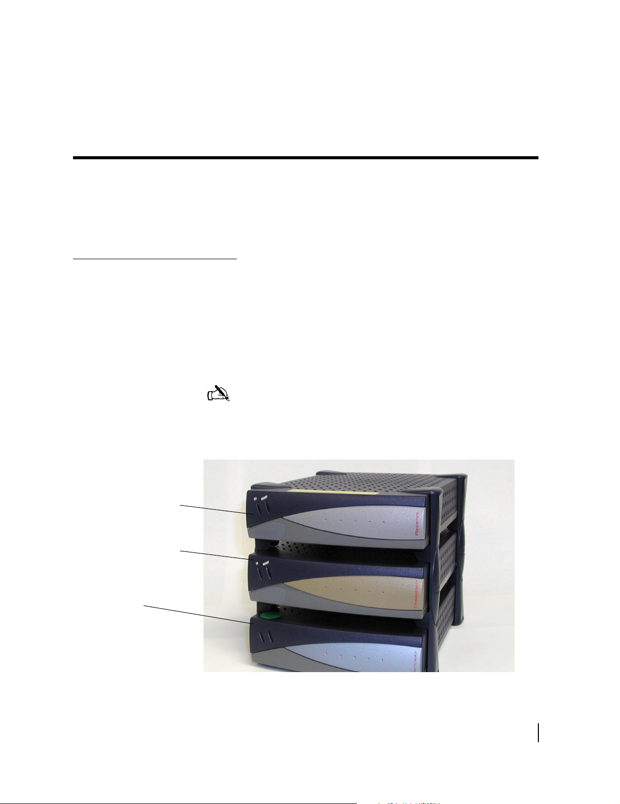
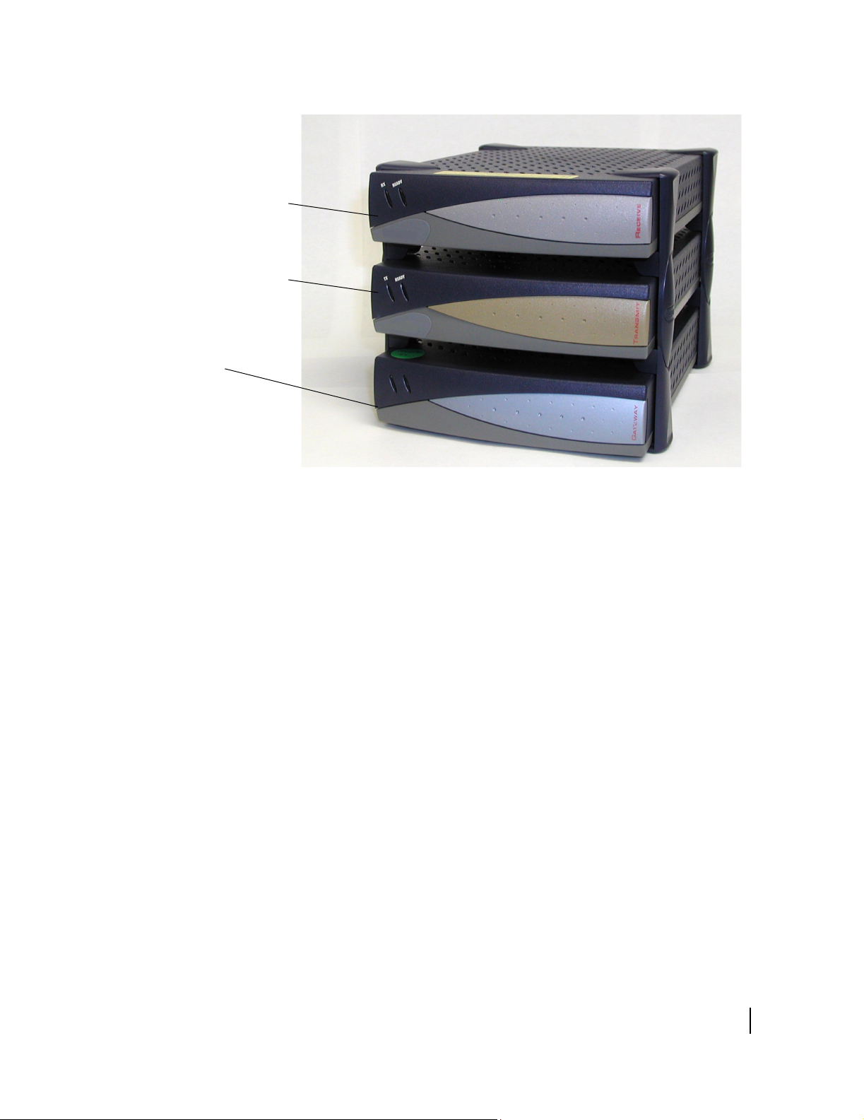
DW4020 purpose and components
Receive modem
Transmit modem
The DW4020 is designed to provide multiple computer
connections through a single DIRECWAY
composed of three stackable components as shown in Figure 1:
• Receive modem (also sometimes referred to as the Indoor
Receive Unit (IRU))
• Transmit modem (also sometimes referred to as the Indoor
Transmit Unit (ITU))
• Gateway (GWH)
Note: Revision 1 of this manual referred to the DW4020 as the
"Gateway," and the Gateway as the "Gateway host." This
terminology has changed. Please use the terminology in this
manual.
terminal. It is
®
Gateway
Figure 1: The DW4020
Chapter 1 • Introduction
1031484-0001 Revision 2
1
Page 14
POS terminal
or other device
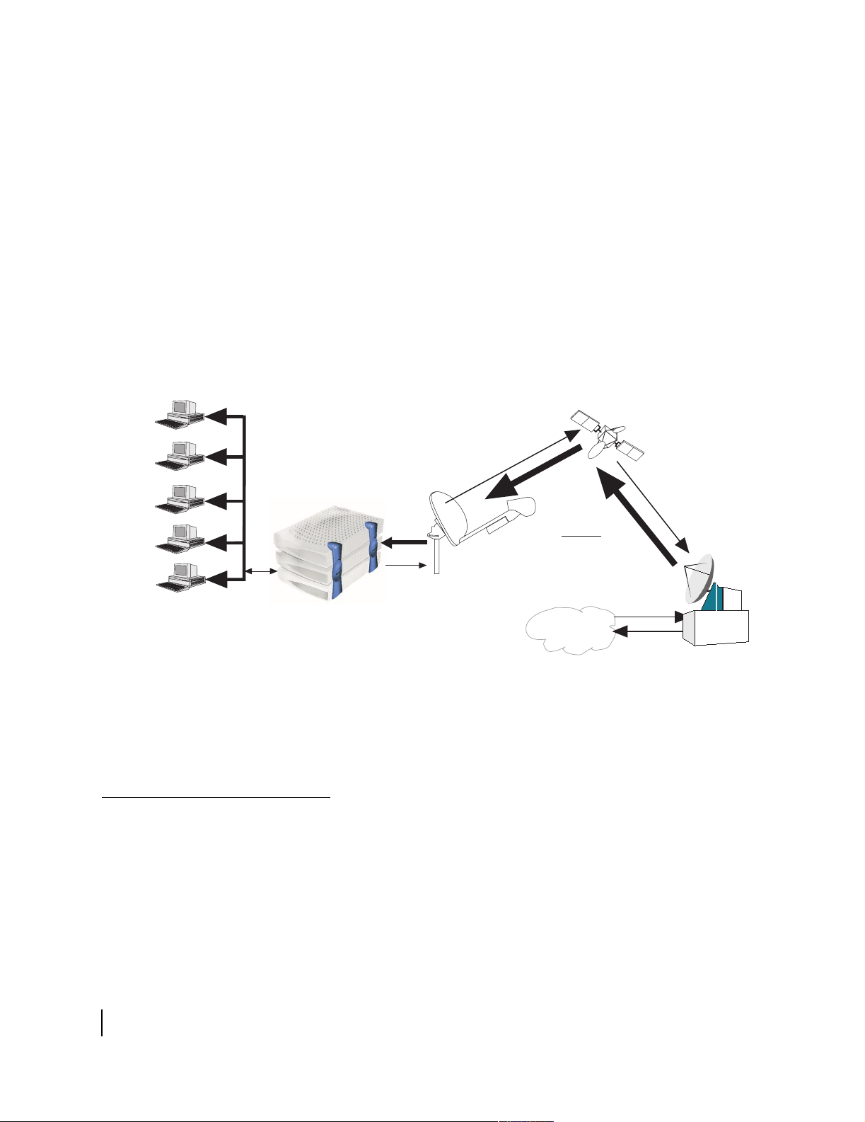
These units, in combination with an antenna, provide satellite
connectivity for multiple local area network (LAN) hosts through
one DIRECWAY System. All the necessary software resides on
the Gateway, which serves as the router. Because the software is
on the Gateway, there is no need for a computer to run client
software, unlike previous versions of DIRECWAY.
Figure 1 illustrates the functionality of the DW4020 within a
DIRECWAY network. Note that the DW4020 is independent of
operating platforms. It can also be used with devices other than
computers, such as point-of-sale (POS) terminals or credit
verification devices.
Satellite
Unix
Mac
PC
Linux
G-25080 F
08/27/02
Ethernet
Characteristics and identification of equipment
Inroute
Antenna
Gateway
Internet
Figure 2: Remote site with DW4020 installed
The part number label is located on the rear of the unit.
Table 1 shows the hardware characteristics of the DW4020.
Table 2 shows the physical characteristics of the unit.
Outroute
DIRECWAY
Network
Operations
Center (NOC)
Chapter 1 • Introduction
2
1031484-0001 Revision 2
Table 3 shows the cable requirements for the unit. The cable
requirements are the same regardless of the type of antenna used.
Page 15

.
Table 1: DW4020 hardware characteristics
Characteristic DW4020
Main processor 200Mhz
Ethernet 10/100 4 ports (switched)
RJ-45
Main Memory 32MB
Flash Memory 8MB
Serial Port Asynchronous RS232
USB Port One USB 1.1 (Type A)
Table 2: DW4020 physical characteristics
Characteristic Value
Physical Dimensions
Height
Width
Depth
Weight
Electrical Requirements
Input line voltage
Input line frequency
Current Required
5.75 inches
6.5 inches
8.8 inches
4.0 lbs.
90 - 264 V ~ 2A max,
50-60 HZ AC
100 W typical
Chapter 1 • Introduction
1031484-0001 Revision 2
3
Page 16

Table 3: Cable requirements
Grounding and Cable Choice
Your choice of grounding scheme may affect your choice of cable. Note that meeting the
National Electrical Code grounding requirements is easier if you use RG-6 with quad shield.
However, you can also use standard RG-6 and ground according to the Code or the
instructions in the antenna installation manual.
Recommended cable specifications for One-Way and Two-Way Systems
Cable length from satellite
dish to DW4020
Up to 300 ft. RG6 with solid copper
300 ft. to 420 ft. RG6 with solid copper
Important: A higher grade of cable can be used for an installation where a lower grade is
specified. For example, an RG6 cable with solid copper center conductor and quad shield
can be used for installations where the cable length is less than 300 ft. Never use a lower
grade of cable than specified. Be sure to record the grade of the cable used for your
installation. The grade is printed on the cable every few feet. Never use a cable which
does not have the manufacturers name and its grade clearly printed on it!
Type of cable to be used
Receive Transmit
RG6 with solid copper
center conductor
(CommScope 5729 or
equivalent)
center conductor
(CommScope 5729 or
equivalent)
center conductor
(CommScope 5729 or
equivalent)
RG6 with solid copper
center conductor and quad
shield (CommScope 5781
or equivalent)
Important notes:
1. Coaxial cables with copper clad steel center conductor are
not recommended.
2. Do not use splitters.
3. Line amplifiers are required for Receive cable runs of more
than 150 ft.
4. If the Receive cable run length is less that 150 ft., then no line
amplifier is required. If the Receive cable run length is
greater than 150 ft., but less than 300 ft., then install a a line
amplifier in the Receive cable only, at a minimum of 25 ft.
and up to 30 ft. from the LNB.
5. A line amplifier can only be installed in the Receive cable,
not in the Transmit cable.
6. Line amplifier specification: Channel Master 5113 IFD or
equivalent.
Chapter 1 • Introduction
4
1031484-0001 Revision 2
Page 17

Chapter 2
Installing the indoor equipment
System pre-installation
Installation PC requirements
Customer installation
requirements
Together, the receive modem, the transmit modem, and the
Gateway are called the DW4020 and sometimes referred to as the
indoor unit (IDU). The receive modem is also called the IRU; the
transmit modem is also called the ITU; and the Gateway is
sometimes called the GWH.
The three units must be stacked correctly to ensure proper heat
dissipation. The receive modem must be installed on top of the
transmit modem, which is in turn installed on top of the Gateway.
See Figure 10 on page 15.
The installer laptop PC must fulfill the following requirements:
• USB port
• Ethernet
• Dial-out modem
• Windows 98 or higher, with DHCP configured to
automatically accept IP addresses. See Appendix D.
• Websetup installed. See Installing DIRECWAY installation
software on installer laptop on page 8.
The customer must have:
• A functioning Ethernet interface installed on at least one
computer. This is not necessary to commission the DW4020,
but you must ensure the customer can surf before you leave.
• Ethernet cables; as many as there are computers that will
connect to the DW4020.
• An analog phone line.
Chapter 2 • Installing the indoor equipment
1031484-0001 Revision 2
5
Page 18

Two DW4020 installation
methods
There two ways to install the DW4020.
• If an analog phone line is available, assemble and install the
system using the instructions in Installing the system using a
modem on page 11. This method is preferred and is usually
the one that will be used.
• If no analog phone line is available, you must configure the
DW4020 through the serial port. Follow the instructions in
Appendix C.
Summary of DW4020
installation process
DW4020 installation is a 10-step process.
1. Assemble the DW 4020 components.
2. Connect the DW4020 to the installer PC Ethernet and power
up the DW4020. Use surge protectors.
3. Connect the installer PC via USB and run Websetup to
establish operating parameters and commission.
4. Register the customer and select subscription options via
Websetup.
5. Record site ID and assigned IP address(es) for the customer
on the cover of the User Guide.
6. Transfer of parameter information to Gateway Host; Exit
Websetup.
7. Assemble and install the satellite antenna. Run cables from
the outdoor components to the indoor equipment. Clearly
label the receive and transmit coaxial cable at the antenna,
ground block, and indoor units connectors.
8. Complete pointing and ACP.
9. Disconnect installer PC and connect the Gateway to the
receive modem with the USB cable. Connect the customer
computer equipment to the Gateway via Ethernet cable.
10. Verify customer operation, information recorded on User
Guide cover, and receive and transmit cable labeling.
Optional: assist in customer computer configuration.
Antenna installation
Chapter 2 • Installing the indoor equipment
6
1031484-0001 Revision 2
The DW4020 can be used with the HNS DW4000 74cm
Two-Way antenna. The DW4020 can also be used in conjunction
with 98cm, 1.2m, and 1.8m antennas. Refer to the manufacturer’s
antenna installation manual for instructions on how to install the
antenna. See the About section for a list of antenna installation
manuals. Follow all safety procedures. Cable requirements are on
page 4.
Page 19
CAUTION
A password from the authorized installer is required before
the National Operations Center will activate the system.
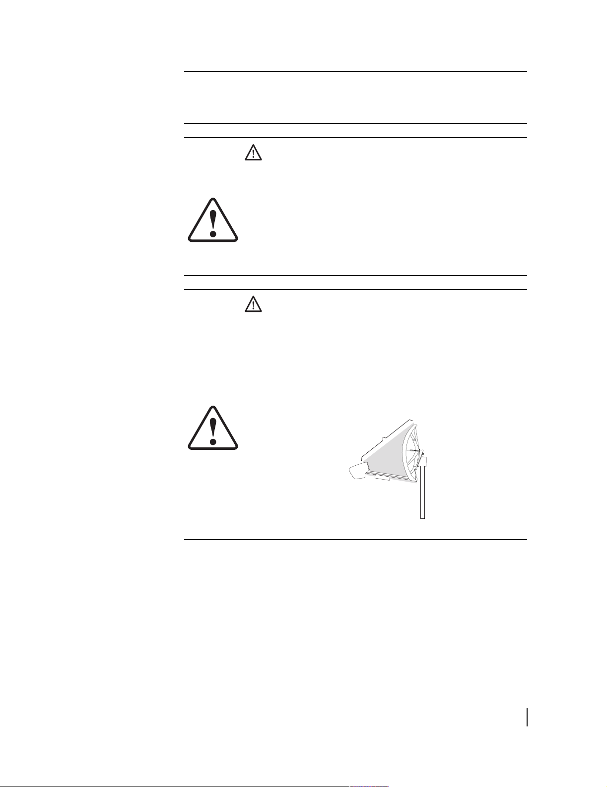
CAUTION
Professional installation and service of the antenna
assembly is required by the Federal Communications
Commission because the radio transmits radio frequency
energy.
• The two-way antenna assembly must be installed in a
location or manner not readily accessible to children.
• The two-way antenna assembly must be installed at
least 5 feet (1.5 meters) above ground level or any
nearby surface on which a person could sit or stand.
CAUTION
• The two-way satellite dish assembly emits radio
frequency energy when in the transmit mode.
• Unplug indoor power connection before performing
maintenance or adding upgrades to any satellite dish
components.
• To avoid risk of injury, do not place head or other body
parts between feed horn and reflector when system is
operational.
Prohibited area
(when operational)
Chapter 2 • Installing the indoor equipment
1031484-0001 Revision 2
7
Page 20

Installing DIRECWAY installation software on installer laptop
The installation software for the DW4020 is on a CD. The
software will enable you to register DW4020 customers. You
need a receive modem (IRU) to install the software on your
installer laptop PC.
Do not confuse the installation software with the software that is
downloaded to the Gateway via satellite during registration. The
DW4020 installation software enables you to register customers
and configure the DW4020 for operation. The software that
actually operates the DW4020 is downloaded during registration.
It is important to understand that there are three service options:
consumer, small office/home office, and enterprise. Each option
has its own registration server that appears in the Websetup
Welcome screen when you start Websetup to register a customer.
You must be careful to choose the correct option. If in doubt
consult the work order.
For example, if you are installing a DW4020 for a SOHO
customer, you would double-click on the registration server for a
SOHO installation. If you click on one of the other servers, you
will not be able to install the customer correctly.
Chapter 2 • Installing the indoor equipment
8
1031484-0001 Revision 2
Page 21
Installing the software
Do not connect USB cable to the receive modem until prompted.
You may use the cable that came with the unit, or a different cable
if you need a longer one.
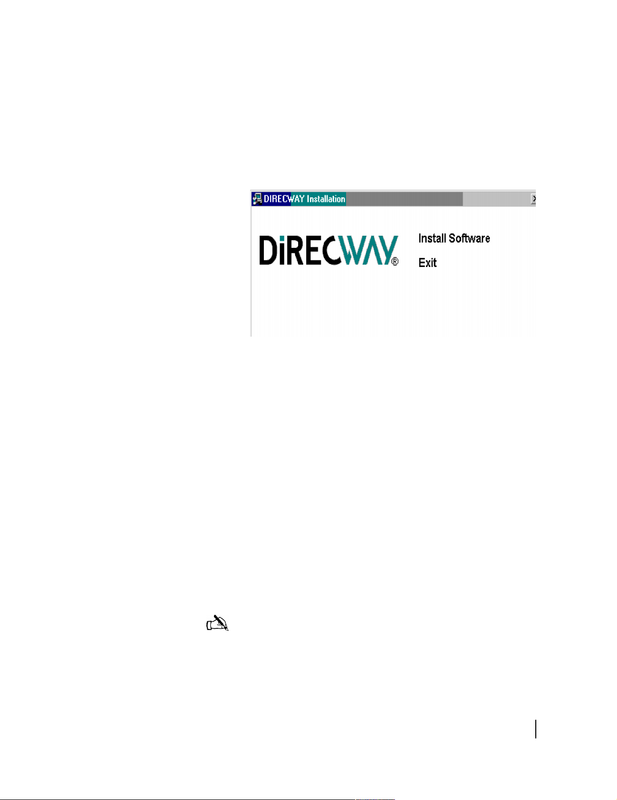
1. Load the installer software CD into your laptop computer.
The installation wizard should appear. If it does not, select
Start→Run, browse to the CD drive, select it, and select
setup.exe.
Figure 3: Installation screen
2. Select Install Software. A
3. Select Next. An
4. Select Ye s. The
Agreement screen appears.
Device Install Status screen in Figure 4
Setup screen appears.
appears.
5. Connect the USB cable. The installation will complete and
Websetup Welcome screen appear. See Figure 5. If you
the
are prompted for the location of your Windows
.cab files,
enter the location or insert your Windows installation CD,
load the files, and re-insert the DIRECWAY installation CD.
If you continue to see the
Device Install Status screen, try the
following:
– Unplug the USB cable and plug it in again.
– Verify you are using the correct power supply.
– Try a different cable.
– Troubleshoot your USB port.
– Try a different receive modem.
6. Select Exit.
Note: If you are using Windows XP as the installer laptop
operating system, the laptop may reboot after you attach the
USB cable. If this occurs, unplug the USB cable and repeat
the installation process after the laptop reboots.
Chapter 2 • Installing the indoor equipment
1031484-0001 Revision 2
9
Page 22

Figure 4: Device Installation Status
Figure 5: Websetup Welcome screen
10
Chapter 2 • Installing the indoor equipment
1031484-0001 Revision 2
Page 23
Installing the system using a modem
Read this manual and obtain serial cable and installation work order
This m
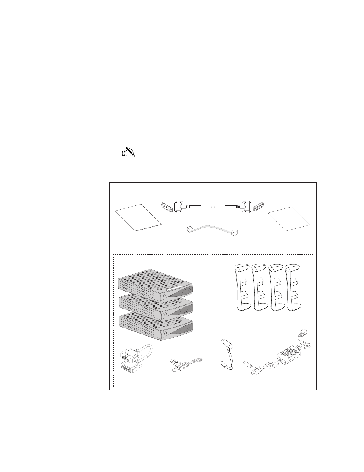
You need all the items shown in Figure 6. Some of them are in the
modem installation kit or inside the antenna box.
If you are using Web commissioning, you must provide an
Ethernet cable to connect between the DW4020 and installer PC.
If Web commissioning is not available, you must provide a 9-pin
female/female (F/F) null modem serial cable. The serial cable can
be used to configure the DW4020 via the serial port. Appendix C
– Installing the DW4020 Manually, on page 77.
You will also need the installation work order. This is provided to
you by HNS.
Note: At some installation sites, the USB cable that comes with
the DW4020 may not be long enough to reach from the installer
PC to the DW4020. You may need a long USB cable.
anual
9-pin F-F serial cable
Install Spec
Installation manual
These items are packaged in a small box inside your antenna box
25-pin connector cable
Figure 6: Items required for installation
Ethernet cable
USB cable
Receive modem
Transmit modem
Gateway
Power adapter
Install specification
Clips
AC cord
DC cord
Power supply
1031105-0001
Chapter 2 • Installing the indoor equipment
1031484-0001 Revision 2
11
Page 24
The power supply
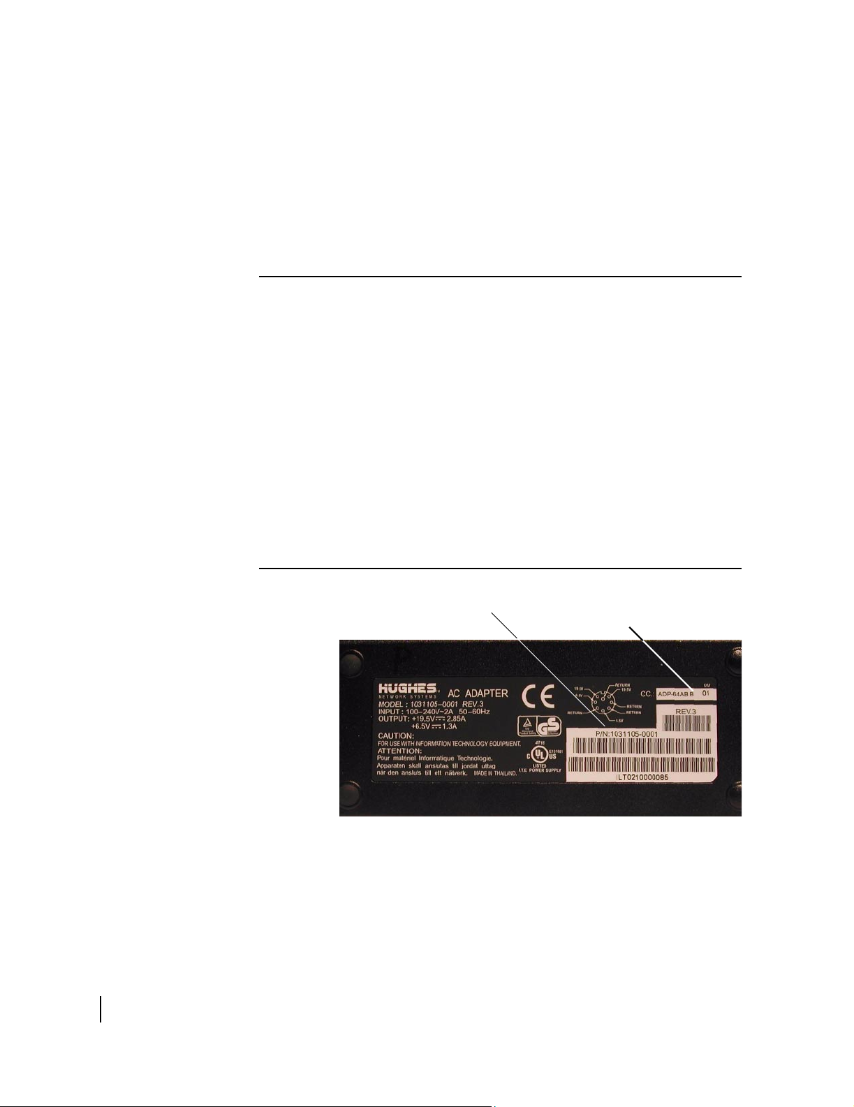
PN: 1031105-0001
The DW4020 uses a power supply with the part number P/N:
1031105-0001. The part number is on a sticker on the power
supply. Verify that you are using the correct power supply. Do not
use anything but the power supply supplied with the DW4020
system (1031105-0001).
Be sure the power supply is labeled ADP 64AB B in the upper
right hand corner of the label, above the bar codes. See Figure 7.
CAUTION
• This unit’s performance may suffer if the wrong power
supply is used.
• This unit must be used with the power supply PN
1031105-0001.
• When power needs to be removed from the receive
modem, ALWAYS unplug the AC power cord from either
the wall outlet, surge protector, or power strip.
• NEVER pull the power cord from the back of the receive
modem. Doing so could damage the pins and also
cause a short in the system.
• Power supply with the part number 1031105-0001 is to
be used only in the United States and Canada.
• This unit must be used with 110-volt AC input.
• Other countries may have different standards and
requirements.
12
Chapter 2 • Installing the indoor equipment
1031484-0001 Revision 2
ADP-64AB B
Figure 7: ADP-64AB B above bar code
Page 25

Assembling the
components, modem
installation method
Follow the steps below and refer to the illustrations on page 13
through page 16 to assemble the DW4020 components. Note that
some cables are connected to the installer laptop until
commissioning is complete. Then the DW4020 is connected to
the customer’s computer.
Before beginning the installation, be sure that you have installed
the installation software correctly. See Installing the software on
page 9. In addition, confirm that DHCP is enabled to accept IP
addresses automatically on your installer laptop PC. See
Appendix D – on page 113.
CAUTION
• The components must be stacked in this order: Gateway
on bottom; transmit modem on top of Gateway; receive
modem on top of transmit modem. See Figure 10.
• If the components are not stacked in the proper order, the
receive modem may overheat and malfunction.
• Do not block any ventilation openings. Do not install near
any heat sources such as radiators, heat registers,
ovens, stoves, or other apparatus (including amplifiers)
that produce heat.
• Recommended ventilation space around the top and
sides of the DW4020 assembly should be approximately 6
inches. Ventilation is necessary to avoid overheating.
1. Be sure the power supply is not plugged into a wall outlet,
surge protector, or power strip.
2. Lay two of the four clips on a table and mount the
components as shown in Figure 8. Mount the Gateway first,
then the transmit modem, then the receive modem.
3. Turn the component stack right side up and install the other
two clips as shown in Figure 9.
Note: The Gateway and the transmit modem have a hole at
the center of each of their four feet. There is a tab on the
bottom of each mounting clip, which snaps into place on the
Gateway when properly aligned over the hole.There is also a
tab in the middle of each mounting clip, which snaps into place
on the transmit modem when properly aligned over the hole.
4. Double-check that the components are installed in this order
from top to bottom: receive modem, transmit modem,
Gateway. See Figure 10.
Chapter 2 • Installing the indoor equipment
1031484-0001 Revision 2
13
Page 26

Figure 8: Mount the components on two clips
14
Figure 9: Attach the other clips
Chapter 2 • Installing the indoor equipment
1031484-0001 Revision 2
Page 27
Receive modem
Transmit modem
Gateway
Figure 10: Component stack
Chapter 2 • Installing the indoor equipment
1031484-0001 Revision 2
15
Page 28
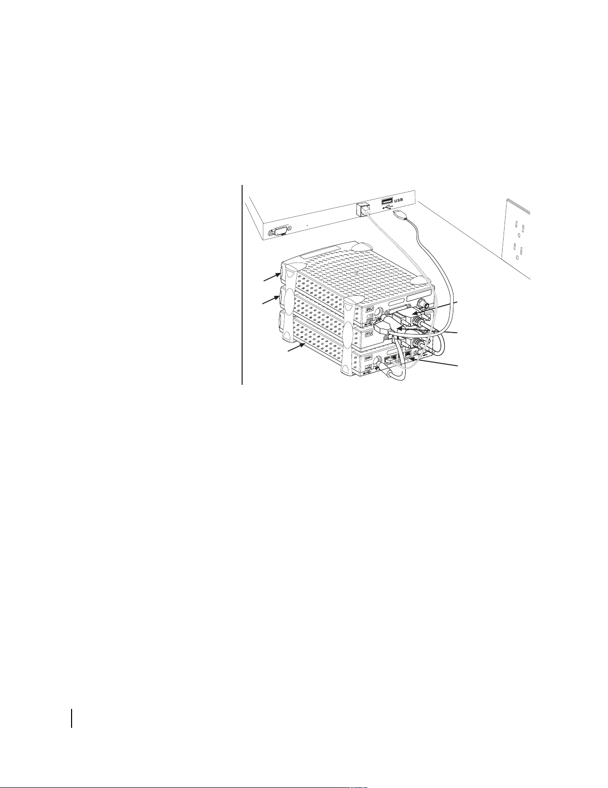
5. Connect the component interconnection cables. See
-
Figure 11. A USB cable connects the receive modem and the
installer PC; you may use a longer cable rather than the one
that is supplied if you wish. An Ethernet cable connects the
Gateway and the installer PC. A 25-pin connector cable
connects the transmit and receive modems. A power supply
adapter cable provides power to the Gateway and receive
modem. See Figure 11.
Installer laptop PC
Ethernet port
Ethernet cable
USB cable
Receive
modem
Transmit
modem
Gateway
25-pin connector
cable
Power supply
adapter
Four 10 Base - T/100
network ports
Figure 11: Attach interconnection cables
6. Attach the power supply cords to the power supply and to the
power adapter. Ensure that the power cord is tightly
connected to the power supply, receive modem, and Gateway.
See Figure 12.
16
Chapter 2 • Installing the indoor equipment
1031484-0001 Revision 2
Page 29
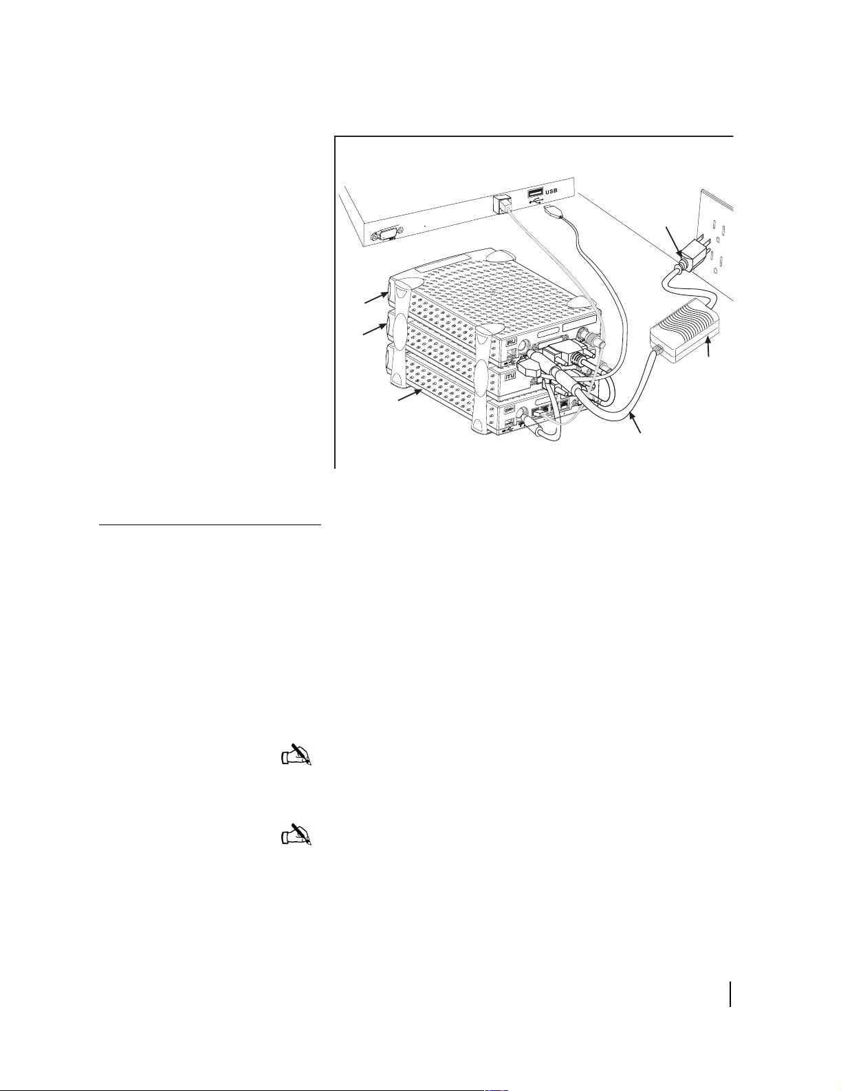
Installer laptop PC
Connect Ethernet, power up, and read the Gateway LED display
Receive
modem
Transmit
modem
Gateway
Ethernet port
Ethernet cable
USB cable
DC power
cord
AC power
cord
Power
supply
Figure 12: Connect power cord
After you assemble the DW4020, connect it to the installer laptop
with Ethernet cable. Plug it into a 110 V wall outlet, power strip,
or surge protector. The Gateway LED display will cycle. The
cycle completes in less than a minute and follows this sequence:
• Gateway STATUS LED is red until the power-on self-tests
are completed.
• Gateway READY LED blinks green because it is not yet
commissioned.
• Gateway STATUS LED blinks orange as it is not attached to
the receive modem.
Note: In countries outside North America, the DW4020 may be
plugged, with a physical adapter, directly into a 220 V outlet.
Different countries may have different standards and requirements.
Note: Whenever the LEDs do not function properly as described
below, check to be sure you have the correct power supply, PN
1031105-0001.
Chapter 2 • Installing the indoor equipment
1031484-0001 Revision 2
17
Page 30

The transmit and receive modems have their own LEDs, which
show their status. These are described in The modems’ LEDs on
page 18.
For more information on LEDs, troubleshooting, and LED
blinking and status codes, see Chapter 4 – DW4020 LEDs and
troubleshooting, on page 53.
Note that normal Gateway operation alone doesn't imply normal
DW4020 operation. The installation and commissioning process
may not have been completed or software download (DLL) from
the Network Operations Center (NOC) may not have been
completed. Additional status information is available via the User
Interface. See Chapter 3 – The User Interface, on page 33) and
the LEDs on the receive and transmit modems. The modems’
LEDs.
Table 4: Gateway LED display
LED condition STATUS LED READY LED
Off Power off Power off or startup
diagnostics not yet run
successfully
Steady Green Normal operation Running software
downloaded from NOC;
successfully
commissioned
Blinking Orange Contact between GWH
and IRU over USB not
established; USB cable
not installed or some
other USB problem
Blinking Green Not applicable Not commissioned
Steady Red Power on tests Not applicable
Not applicable
18
Obtain IP address and test
Ethernet connection
1. Restart the PC so that the Gateway assigns it an IP address.
Or use the command
command line prompt.
2. The embedded DHCP server assigns IP address =
192.168.0.2 to the PC. The DW4020 Address is set to
192.168.0.1.
3. Make sure the PC can communicate with the DW4020 over
the Ethernet connection. Enter
DOS prompt.
The modems’ LEDs
The receive and transmit modems have LEDs on their front
panels. Both modems have a green R
modem has a green RX LED. The transmit modem has a green
Chapter 2 • Installing the indoor equipment
1031484-0001 Revision 2
ipconfig /renew from a DOS
Ping <192.168.0.1> at a
EADY LED. The receive
Page 31

TX LED. The LEDs’ status indicate various conditions. Table 5
describes the basic states.
The LEDs may also indicate various conditions through blink
patterns. The numbers in brackets are the status codes discussed
in The System Status indicator on page 36.
If the modem does not appear to be functioning, check all cable
connections. If they are secure, cycle the power by unplugging
the power cord at the power supply and plugging it back in. A
number of conditions and corrective actions are described in
Chapter 4 – DW4020 LEDs and troubleshooting, on page 53.
EADY LEDs should come on steady when the DW4020 is
The R
powered up, commissioned, and when it is operating. The TX and
RX lights can also blink when the DW4020 is first powered up, or
when the DW4020 is power cycled. However, that blinking does
not indicate anything about their status.
Table 5: Basic Receive and Transmit Modem LED States
Ready OFF/RX OFF Ready ON/RX Off Ready ON/RX
Receive modem Modem not functioning Modem functioning, no
data being received
Ready OFF/TX OFF Ready ON/TX Off Ready ON/TX blinking
Transmit modem Modem not functioning Modem functioning, no
data being transmitted
blinking
Modem functioning,
data being received
Modem functioning,
data being transmitted
The DW4020 is extremely reliable. If you find you cannot surf
the Internet or the DW4020 seems to have a problem, follow this
sequence of steps below to identify and fix the problem.
• Check whether the DW4020 LEDs are on or off. The LEDs
may indicate that a connection has become loose.
Reconnecting a cable or power cord may restore function.
• Check if the LEDs are blinking in a pattern. The LEDs can
blink in a pattern. The patterns correspond to the receive and
transmit status codes discussed in Transmit Status messages
on page 37 and Receive Status messages on page 42. See
LED blinking indicating status codes on page 60 for a
discussion of the blinking LEDs.
• Check if the LEDs on the back of the Gateway or on or off.
The LAN ports on the back of the Gateway have LEDs. See
Ethernet port LEDs on page 20.
• Contact technical support. If the corrective actions described
in this chapter and Chapter 3 – The User Interface do not
solve the problem, contact technical support.
Chapter 2 • Installing the indoor equipment
1031484-0001 Revision 2
19
Page 32

Ethernet port LEDs
Each of the four Ethernet ports on the DW4020 has two LEDs
associated with it. One LED is green and one is yellow. See
Figure 13.
The green LED will be on if power is applied to the DW4020 and
a 100baseT Ethernet device is connected to the corresponding
Ethernet port. Otherwise, the green LED will be off.
If the power is on and the light is off while a network device is
connected, then the device is a 10baseT device and the port is
autosensing.
The yellow LED will also be on when power is applied to the
DW4020. It will flash momentarily when there is LAN activity
on the corresponding Ethernet port.
Green LED Yellow LED
Figure 13: Ethernet port LEDs
20
Chapter 2 • Installing the indoor equipment
1031484-0001 Revision 2
Page 33

Running the DW4020 installation software, commissioning, and registering the customer
The DW4020 installer’s computer software is basically
DIRECWAY 4.0 software with some functions, such as
interacting with a browser, removed. It is used to run Websetup
and commission the customer.
There are three registration servers, one each for consumer, small
office/home office, and enterprise. Before you select the
registration server, check the work order and confirm which
service option the customer has chosen.
You will connect the installer laptop and receive modem, register
the customer, peak the satellite signal, connect the customer’s
DW4020, and confirm that they can surf the Internet.
1. Connect the receive modem to the installer laptop PC with
the USB cable.
2. Connect the installer laptop PC to an analog telephone line
or alternate connection to the Internet.
3. Select
Start→Programs→Direcway Installer→Websetup. The
Welcome screen appears. Check the work order for the
service option and highlight the proper registration server.
The select Next. Follow the instructions on subsequent
screens; the instructions below will supplement the onscreen
instructions.
Welcome screen does not appear, the receive modem is
If the
not connected to the PC or there is a problem with the receive
modem installation. Check cable connections. If cable
connections are not the problem, restart the PC. If that does
not solve the problem, call technical support.
Figure 14: Welcome screen; choose proper registration server
Chapter 2 • Installing the indoor equipment
1031484-0001 Revision 2
21
Page 34

4. Websetup will first detect the Gateway and the modem. See
Figure 15.
5. Then Websetup will check for an existing connection to
WebACS. Websetup may bring up a dial-up connection if
necessary. See Figure 16.
Figure 15: Websetup - Detection
22
Figure 16: Dial up connection may be necessary
Chapter 2 • Installing the indoor equipment
1031484-0001 Revision 2
Page 35

Figure 17: Registration Connection - Authentication
6. Websetup will then authenticate the receive modem serial
number and enable it. See Figure 17.
7. Websetup then presents a series of forms to the user to
complete registration. See Figure 18 through Figure 20. The
appearance of the forms may vary, and the forms’ content
may change from time to time. For example, a SOHO
customer Service Offerings screen shown in Figure 19will be
different from a consumer screen.
Figure 18: Agreement
Chapter 2 • Installing the indoor equipment
1031484-0001 Revision 2
23
Page 36

Figure 19: Service Offerings
Figure 20: Registration
Note: The registration information in Figure 20 is very
important. Make certain this information is recorded on
the cover of the customer’s User Guide. That way the
customer will have important information available
should their DW4020 not function and they need to call
technical support.
24
Chapter 2 • Installing the indoor equipment
1031484-0001 Revision 2
Page 37

8. After the customer enters registration information, write the
information in Figure 20 on the cover of their User Guide.
9. Select
Antenna Pointing - Antenna Location screen appears. See
Continue in the Registration screen in Figure 20. The
Figure 21.
Figure 21: Enter ZIP code
10. Verify that the ZIP code shown matches the ZIP code for the
installation site. If not, correct it. Select Next. The
Pointing - Receiver
screen appears. See Figure 22. At this
Antenna
point it shows no signal strength or auto cross-pol checkbox.
11. Click through all pointing screens by selecting Next. Click
through until you reach the
Websetup - Finish screen. You
will finish registration before peaking the signal.
Note: You must not disconnect the power cables before
completing Step 13. Finish registration before peaking the signal.
12. When the
Websetup-Finish screen appears, Websetup
receives a parameter file from the WebACS and transfers it to
the DW4020 over the Ethernet connection. If it is successful,
a message appears asking you to press Finish. See Figure 23.
13. Select Finish. The unit is commissioned. A message may
appear telling you to connect and reconnect the USB cable.
Click OK. You do not need to do anything with the USB
cable at this time.
Chapter 2 • Installing the indoor equipment
1031484-0001 Revision 2
25
Page 38

Figure 22: Antenna Pointing - Receiver
Figure 23: Finish
26
Figure 24:
Chapter 2 • Installing the indoor equipment
1031484-0001 Revision 2
Page 39

Post-commissioning
In post-commissioning, you peak the satellite signal, attach the
DW4020 to the customer computer that has a functioning
Ethernet interface, and confirm the customer can surf the Internet.
Peak the satellite signal
1. Unplug the DW4020 power cord from the wall outlet or surge
protector.
2. Remove the phone line and network cable from the installer
laptop PC.
3. Remove the network cable from the Gateway and unplug the
USB cable from the receive modem.
4. Connect a long USB cable from the back of the receive
modem to the installer laptop PC.
5. Assemble and install the satellite antenna.
6. Place the outdoor pointing interface (OPI) in the receive
cable line if applicable.
7. Power on the DW4020.Select
Installer
Location
→Antenna Pointing. The Antenna Pointing - Antenna
screen appears. See Figure 25.
Start→Programs→DIRECWAY
8. Verify the ZIP code matches the antenna location and select
Next. The
Antenna Pointing - Receiver screen appears. Check
the Longitude, Hemisphere, and Frequency values. See
Figure 26.
Figure 25: Antenna Location; verify ZIP code
Chapter 2 • Installing the indoor equipment
1031484-0001 Revision 2
27
Page 40

Figure 26: Antenna Pointing - Receiver
9. Use the Elevation, Azimuth and Polarization values to adjust
the antenna to achieve maximum receive signal strength.
10. Select the ACP (auto cross-pol) checkbox. If it is not
available, wait five minutes; the system will update.
11. Select Next to go to the
Antenna Pointing - Transmitter
screen. See Figure 27.
28
Figure 27: Start manual cross-pol; pass and peak isolation
Chapter 2 • Installing the indoor equipment
1031484-0001 Revision 2
Page 41

12. Select the Manual fine pointing mode radio button.
13. Select Start Test. Adjust the antenna to achieve maximum
transmit isolation.
14. When the unit consistently passes the manual transmit test,
bolt the antenna securely before going to Step 15.
15. After the antenna is bolted, select
16. Then select the
Automatic radio button and select Start Test
Stop Test. See Figure 28.
to start the automatic ACP test. See Figure 29.
17. Make sure the test passes.
18. Select Exit after passing the test.
Figure 28: Manual cross-pol passed; select Stop Test
Figure 29: Auto cross-pol
Chapter 2 • Installing the indoor equipment
1031484-0001 Revision 2
29
Page 42

Figure 30: ACP passes; select Exit
Connect to customer
computer and confirm
surfing
1. Disconnect the USB cable from the installer’s PC.
2. Connect the receive modem to the Gateway using the USB
cable supplied with the unit. See Figure 31.The DW4020 will
re-initialize and come back up in normal mode.
3. Connect the receive coaxial cable to the receive modem and
the transmit coaxial cable to the transmit modem. See
Figure 31.
4. Plug the power cord into the wall outlet or surge protector.
5. Make sure that the READY LEDs on all three units are
STEADY GREEN. Make sure the transmit and receive cables
are clearly labeled at the connectors.
6. The DW4020 is now commissioned. Connect the customer’s
computer and the Gateway with Ethernet cable. See
Figure 31. If the computer has a functioning and properly
configured Ethernet interface, it will surf the Internet. If the
customer cannot surf, see the instructions below.
30
Chapter 2 • Installing the indoor equipment
1031484-0001 Revision 2
Page 43

If the customer cannot surf
If the customer cannot surf, configure your installer laptop so its
network properties match the customer’s. Refer to Appendix D for
exact instructions for setting your network properties. Then:
1. Start a Web browser on the installer laptop.
2. Enter the Gateway IP address in the browser URL location
bar and press Enter. If the DW4020 is functioning, the User
Interface appears.
3. Enter an URL for a known Web site, such as abc.com or
cnn.com. If it appears, the DW4020 is functioning and any
problem exists on the customers computer. The customer’s
network properties may not be configured properly, or there
may be some other system problem. They should consult the
User Guide for support information.
Ethernet
AC power
cord
Receive
modem
Transmit
modem
Gateway
T0091020
Short USB cable
Figure 31: Final cabling
Ethernet cables
DC power
cord
Power
supply
Chapter 2 • Installing the indoor equipment
1031484-0001 Revision 2
31
Page 44

32
Chapter 2 • Installing the indoor equipment
1031484-0001 Revision 2
Page 45

Chapter 3
The User Interface
In the Version 1.0 software, DW4020 status information was
available on menus accessed through the serial port via
Hyperterminal. In the Version 2.0 software, a browser-based User
Interface provides information about system status, system
configuration, online documentation, and firewall configuration.
Access it if the DW4020 doesn’t seem to be functioning properly,
to find system information for configuring networks, or to check
system performance. Clicking on items highlighted in blue
displays help information or other documentation.
Note: The information about the DW4020 User Interface in this
manual is the same as that in the DW4020 User Guide (HNS
1032564-0001 Rev A). Each DW4020’s software is updated
periodically via satellite link. The updates should be reflected in
User Interface Help if they are not documented in the User Guide
or in this manual. Always refer to User Interface Help and the
latest revision of the User Guide, as well as this manual, for the
latest information about the User Interface and DW4020 software.
If at any time you are unable to access the User Interface, take the
steps below:
• Make sure the Gateway is powered up. The STATUS and
READY LEDs should be lit continuously. If they are not,
power cycle the DW4020 by unplugging the power cord from
the wall outlet or surge protector, waiting 10 seconds, and
plugging it back in. Refer to the Chapter 5 Troubleshooting
for more information.
• If the User Interface is still not accessible, check the Ethernet
cable connection from the computer to the DW4020. Check
that the power adapter is securely attached to the receive
modem and Gateway. Also check the computer’s network
configuration.
• If the User Interface is still not available, contact technical
support.
Chapter 3 • The User Interface
1031484-0001 Revision 2
33
Page 46

How to access the User Interface
The User Interface is accessed through any browser, such as
Internet Explorer or Netscape. Follow the steps below to set up an
entry for the User Interface in a browser. The steps are written for
Internet Explorer or Netscape, but you can use a similar
procedure for any browser.
1. Go to
2. Place the cursor in the Internet Explorer Address bar or the
3. Type the DW4020 IP Gateway address. The should have been
4. Press E
Start→Programs→Internet Explorer (or Netscape). The
browser interface appears.
Netscape Location Bar.
written this on the front of this manual when the installer
finished configuring the unit.
NTER. The User Interface Home screen appears. See
Figure 32. .
34
Figure 32: The User Interface Home screen
Chapter 3 • The User Interface
1031484-0001 Revision 2
Page 47

The Home screen
The Home screen has system indicators across the top. There are
menu items in a column along the left. The system indicators
consist of the following:
• System Status reports the strength of the receive signal, the
status of the receive and transmit modems, and software
download status. If
DW4020 is functioning properly. If there is a problem, it is
colored red and the word “PROBLEM” appears below
System Status. See Figure 33.
• Receive Statistics reports data on receive modem
functioning.
• Transmit Statistics reports data on transmit modem
functioning.
• System Information provides information such as the
Gateway IP address, subnet mask, site ID, and what features
are enabled.
System Status is colored green, the
Figure 33: System Status reports PROBLEM
Chapter 3 • The User Interface
1031484-0001 Revision 2
35
Page 48

The System Status indicator
Clicking on System Status will display a System Status screen.
See Figure 34.
Figure 34: System Status screen
The screen consists of the following fields.
• Signal Strength - indicates the signal quality factor (SQF),
which is the strength of the receive signal. If SQF is 30 or
below, the antenna must be repointed by a certified
professional installer.
• Transmit Status - indicates the status of the transmit modem.
• Receive Status - indicates the status of the receive modem.
• Software Download Status - indicates the status of the
downloading of software from the Network Operations
Center (NOC). If the DW4020 has been commissioned, this
message will generally indicate that software download has
been completed. Occasional updates are automatically
downloaded to the DW4020 from the NOC. The purpose of
these updates is to enhance DW4020 performance.
Remember that this software is not placed on the customer’s
computer, but on the DW4020. No action is required from
them. The software version number in the
Information
downloaded software. See System Information on page 45.
page indicates the current version of the
System
36
Chapter 3 • The User Interface
1031484-0001 Revision 2
Page 49

If there is a problem with any of these four status elements, a red
exclamation mark will appear in the status field. In addition, if
there is a problem with the
error message and an error code will appear in blue. You can click
on the error message and an explanation of the error condition
and what action might solve it will appear. See Figure 35. The
tables below provide a more detailed explanation of status codes,
error messages, and corrective actions.
Transmit Status or Receive Status, an
Figure 35: On-line help for status messages
Transmit Status messages
The following messages may appear in the Transmit Status field.
The Comments section gives more information about each code,
and describes any possible corrective measures. See Figure 36 on
page 41 for corrective measure involving cables or the power
supply. Power cycling means to unplug the power cord from the
wall outlet or surge protector, wait 10 seconds, and plug it back
in.
Chapter 3 • The User Interface
1031484-0001 Revision 2
37
Page 50

If corrective measures do not solve a problem, contact technical
support.
TxCode 8 means the transmit modem is working properly. It is
the code you will see most of the time.
Note: Remember that IRU refers to the receive modem, and that
ITU refers to the transmit modem.
Table 6: Transmit status (TxCode) messages and corrective actions
Numeric
TxCode
0 The transmitter is not
1 The transmitter has been
2 The transmitter has been
3 The transmitter is locking to
4 The transmitter is not
Message Displayed Comments
connected to the receiver
disabled by the Network
Operations Center
placed in test mode by the
Network Operations Center
the receive carrier
responding to commands sent
from the receiver
This status will occur only if the Indoor Transmit Unit (ITU) is not connected to
the Indoor Receive Unit (IRU). It can result for the following reasons:
• The 25-pin parallel cable is not properly connected to the Indoor Receive Unit
or Indoor Transmit Unit: Check the cable and make sure the ends are securely
fastened.
• Indoor Transmit Unit failure. The Indoor Transmit Unit has failed and may need
to be replaced.
This condition occurs when the transmitter is not enabled. A transmitter may be
disabled for short periods of time by the NOC for service or troubleshooting. It
may also be disabled if the user discontinues the satellite service. If this
condition persists, it can only be corrected by requesting that the unit be
enabled.
This status requires no user action and this test usually completes in 15 minutes
or less. This condition occurs when the NOC places the transmitter into special
transmission modes to measure the performance of the transmitter. When in this
mode, the unit is unable to transmit normal user data to the NOC.
This condition occurs during initial startup or when the receiver is locking to the
receive signal. It is normal for this condition to persist for up to 10 seconds. If this
condition
persists for more than 10 seconds, try disconnecting and reconnecting the
receiver coaxial cable and wait 10 seconds. If the situation still persists, then the
Indoor Transmit Unit may need to be replaced.
This condition indicates that something is not operating properly in the
Receive/Transmit Unit configuration. Perform the following actions to attempt to
recover from this condition:
38
• Verify that the Indoor Receive and Transmit Units are securely connected with
a 25-pin parallel cable.
• Reset the IRU by unplugging the IRU power cord from the wall socket and then
plugging the power cord back into the wall socket. This will reset the Indoor
Receive and Transmit Units.
This condition could also be caused if the power supply is faulty. If this condition
cannot be resolved by following the steps listed above, then you may need to
replace the power supply, the Receive/Transmit unit cable and/or the Transmit
Unit.
Chapter 3 • The User Interface
1031484-0001 Revision 2
Page 51

Table 6: Transmit status (TxCode) messages and corrective actions
5 The transmitter is not locked to
the network timing
6 The transmitter is not available
because the receiver is not
detecting a signal or is not
locked to the correct
network
7 The transmitter is not available
because the satellite receiver
is not tuned for normal
operation
8 The transmitter is available This is the normal operational state and indicates that the transmitter is ready to
9 The transmitter is adjusting for
optimal network timing
10 The transmitter is unable to
communicate with the Network
Operations Center
11 The transmitter is not available
because the receiver software
is out of date
12 The transmitter is not
receiving network control
messages from the Network
Operations Center
13 The transmitter is unable to
range because it cannot
communicate with the
Network Operations Center
No action is necessary if this condition occurs from time to time and quickly
resolves itself. If this issue persists, it is likely due to a NOC-related service
issue. The condition may also be due to Indoor Transmit Unit failure; in rare
cases, the Transmit unit may fail and may have to be replaced.
Check your receive signal. This condition occurs when the Indoor Receive Unit is
not receiving a good signal. The receiver must be locked to the correct network
in order for the transmitter to operate. If the receiver is not locked (no signal) or is
locked to the wrong network, the transmitter is unable to transmit data. Please
verify that you have a good signal strength by going to the Receive Statistics
page. This could also be caused by inclement weather.
This condition occurs when the transmitter is disabled for safety reasons. If this
happens during installation or commissioning, the installer will close the Antenna
Pointing program and resolve the condition.
transmit data.
This condition typically occurs when the DW4020 is first commissioned or the
first time it is used for data traffic. This must occur before the Indoor Transmit
Unit is able to transmit successfully. Typically, this process usually takes less
than a minute.
This condition indicates that the unit has stopped attempting to transmit user
data because there were a number of failures in sending data to the NOC over
the satellite link. This could be the result of weather conditions causing lost
packets or return channel equipment failures in the NOC.
This condition indicates that the installed software version is not recent enough
to operate on the network. New software will be required from time to time due to
network infrastructure and capability upgrades and in order to maintain network
efficiency and fix any known problems.The system will automatically update the
software version to ensure that you can enjoy uninterrupted operation. If you do
not use the DW4020 for a long period of time and miss the updates, you may
need to contact Customer Care.
This condition indicates a NOC equipment outage. This may be a transient
condition and the system should recover automatically.
Ranging is the process that adjusts the satellite transmitter timing and
power. The satellite transmitter conducts ranging as needed to ensure
that it can communicate successfully with the Network Operations
Center.This condition can indicate any of the following:
• The NOC is not receiving ranging information from the transmitter. This may
indicate a transmit problem at the NOC. This should get cleared in a few
minutes.
• The transmitter is unable to achieve enough transmit power to send ranging
information to the NOC. Make sure that the power supply is correct. The power
supply should be Part #1031105-0001.
• The transmitter is sending incorrect timing data because the wrong zip code or
latitude/longitude information was entered during installation.
• The outdoor transmitter unit (ODU)--that is, the antenna--is not operating
properly or is not properly connected to the ITU. Please ensure that the
transmit cable is securely fastened to the Transmit Unit.
Chapter 3 • The User Interface
1031484-0001 Revision 2
39
Page 52

Table 6: Transmit status (TxCode) messages and corrective actions
14 The transmitter is not available
because ranging has failed
15 The transmitter is waiting for a
ranging request to be
processed by the Network
Operations Center
16 The transmitter is waiting for a
transmit request to be
processed by the Network
Operations Center
17 The satellite transmitter is
unable to obtain an available
transmission rate
18 The transmitter is requesting a
transmit pointing test
19 The transmitter is queued for a
transmit pointing test
20 The transmitter is performing a
transmit pointing test
This condition indicates that the transmitter is not operational because ranging
has failed. Ranging is the process that adjusts the satellite transmitter timing and
power. The satellite transmitter conducts ranging as needed to ensure that it can
communicate successfully with the Network Operations Center. The ranging
failure may happen due to the antenna becoming misaligned or if repeated
attempts to range do not succeed. This condition may also be caused due to
adverse weather conditions. In rare cases, this may also indicate NOC issues
but should clear within a few minutes.If the system was operational in the past
and you see these messages repeatedly, you can try to force range by
performing the Connectivity Test.
This condition occurs if the system is busy adjusting power and timing for other
users. This process may take up to a minute or more.
This condition occurs when the system is unable to provide transmit bandwidth.
This occurs when many users sign-on simultaneously. It should clear in a few
minutes automatically.
This condition occurs if the transmitter cannot successfully range. Ranging is the
process that adjusts the satellite transmitter timing and power. The satellite
transmitter conducts ranging as needed to ensure that it can communicate
successfully with the Network Operation Center. A possible cause is that the
transmitter could not achieve enough power to transmit. This is likely caused
because the antenna is not accurately pointed. However, it may also be a
transmitter power problem. Check the power supply and make sure that it is Part
# 1031105-0001.
This condition can occur during installation when the Antenna Pointing program
on the installation computer requests that the transmitter perform a transmit
pointing test. This condition persists until the NOC responds that the transmitter
is either actively performing the pointing test or is queued to perform the test
when test resources become available in the NOC. This is a normal condition for
initial installation. The transmitter may also periodically go into this condition for
short periods of time (less than 5 seconds) to perform periodic transmit pointing
tests. These periodic tests are performed to ensure that the antenna is pointed
accurately.
This condition can occur during installation when the Antenna Pointing software
on the installation computer requests a transmit pointing test and the NOC has
responded that the transmitter is queued for the next available test time. It may
also occur when the transmitter is performing periodic background transmit
pointing tests at the same time that other users on the network have requested
tests. This is a normal state after initial installation.
This condition occurs when one of the following tests are active:
• During installation, the Antenna Pointing software requests that the transmitter
perform a transmit pointing test. This condition will persist until the Antenna
Pointing software exits from the transmit pointing test mode.
• The DW4020 performs a periodic background transmit pointing test to make
sure that the antenna is still pointed correctly. This periodic test takes less than
5 seconds.
If the problem persists, try power-cycling the DW4020 by unplugging the wall
outlet and plugging it back in.
40
Chapter 3 • The User Interface
1031484-0001 Revision 2
Page 53

Table 6: Transmit status (TxCode) messages and corrective actions
21 The transmitter is disabled
because a transmit pointing
test failed
22 The transmitter is disabled
pending a transmit pointing
test
23 The transmitter is disabled
because a transmit pointing
test cannot be performed
This condition occurs when the transmitter fails a transmit pointing test. This
indicates that the transmitter did not meet the minimum specifications required.
This is likely due to an antenna installation problem. The antenna installer needs
to fine-point the antenna. The transmitter will not transmit until the transmit
pointing test passes.
This condition occurs when the transmitter is required to perform a periodic
background transmit pointing test, but has not been able to perform the test
within the time window required. The transmitter is expected to be in this
condition for no more than two minutes at random periodic intervals. This
condition can also occur after the transmitter is first powered on after it has been
powered off for more than a day. If the unit remains in this condition for more
than two minutes, then the automated transmit pointing components in the NOC
are likely experiencing problems. This condition should clear in a few minutes.
This condition occurs when the transmitter cannot perform the transmit pointing
test when initially installed or when the transmitter is required to range. The
condition indicates that the NOC components needed to perform the transmit
pointing test are not operational.
Ethernet card
Receive
modem
Transmit
modem
Gateway
T0091013
AC power
cord
Power
supply
DC power
cord
Ethernet cables
Figure 36: DW4020 connections
Chapter 3 • The User Interface
1031484-0001 Revision 2
41
Page 54

CAUTION
Never unplug the power cord from the DW4020 while it is powered
on. Always disconnect the power cord from the power supply, wall
outlet, or surge protector.
Receive Status messages
The following messages may appear in the Receive Status field.
The Comments section gives more information about each code,
and describes any possible corrective measures. See Figure 36 on
page 41 for corrective measure involving cables or the power
supply. Power cycling means to unplug the power cord from the
wall outlet or surge protector, wait 10 seconds, and plug it back
in.
If corrective measures do not solve a problem, contact technical
support.
RxCode 5 means the receive modem is working properly. It is the
code you will see most of the time.
Note: Remember that IRU refers to the receive modem, and that
ITU refers to the transmit modem.
Table 7: Receive code (RxCode) messages and corrective actions
Numeric
RxCode
0 The receiver is not connected Please make sure that the Indoor Receive Unit is connected to the
1 The receiver is in pointing mode This condition indicates that the installer is performing antenna
2 The receiver is in factory or NOC mode This status is for DW4020 testing purposes only. You should never
Message Displayed Comments
Gateway via the USB cable. If the cable is connected and you still
see this message, use the following steps for troubleshooting:
• Make sure the power supply is correct. The power supply should
be Part # 1031105-0001.
• Try power-cycling the DW4020 by unplugging the power cord
from the wall outlet and then plugging it back in.
• Try using a different USB cable.
• If none of the above resolve the issue, you may need to replace
the Indoor Receive Unit.
pointing. In this mode, the transmitter is disabled for safety
reasons since the installer is working near the dish. If this occurs
during normal operation, try power-cycling the DW4020 by
unplugging the power cord from the wall outlet and then plugging
it back in.
see it. If this occurs during normal operation, try power-cycling the
DW4020 by unplugging the power cord from the wall outlet and
then plugging it back in.
42
Chapter 3 • The User Interface
1031484-0001 Revision 2
Page 55

Table 7: Receive code (RxCode) messages and corrective actions
3 The receiver is not locked to a signal If the DW4020 had been operating previously, this status is
probably due to inclement weather conditions and will be
corrected when the weather improves. This condition can also
indicate that the IRU is unable to receive the signal from the NOC.
This is also associated with a signal level less than 30. This
occurs if there is a weather outage at the user location, a NOC
outage due to inclement weather or other reasons, a misaligned or
faulty antenna, or faulty cabling. If this keeps happening under
normal weather conditions, make sure the power supply is correct.
The power supply should be Part # 1031105-0001. If the power
supply is correct, try power-cycling the DW4020 by unplugging the
power cord from the wall outlet and then plugging it back in.
4 The receiver is locked to the wrong network This condition should only be seen during installation and occurs
when the receiver is locked to a signal, but the signal ID does not
match the ID that was assigned to the user during commissioning
or the ID that was entered by the installer during manual pointing.
If this occurs during normal operation, it may be due to the user
changing acquisition parameters, including frequency and/or
location of satellite, or the antenna becoming misaligned.
5 The receiver is operational This is the normal operating state where the receiver is receiving
data from the NOC. Only when the receiver is in this state will the
transmitter operate correctly.
6 The receiver is not detecting a signal This condition occurs when the IRU is not detecting any type of
radio signal from the antenna. This could indicate that the cabling
between the receiver and the antenna is faulty or that the receiver
itself is faulty. Check that the cables are firmly connected on the
DW4020. Also, make sure that the power supply is correct. The
power supply should be Part # 1031105-0001. Try power-cycling
the DW4020 by unplugging the power cord from the wall outlet
and then plugging it back in.
7 The receiver is locked to an unknown
network
This condition should only be seen during installation and occurs
when the receiver is locked to a signal but there is no DIRECWAY
Network ID on that signal. If this occurs during pointing or
commissioning, the antenna has not been pointed correctly. If it
occurs during normal operation, it may be due to the user
changing acquisition parameters, including frequency and/or
location of satellite, or the antenna becoming misaligned. The
former condition can be corrected by re-commissioning the site.
The latter requires an antenna repointing.
Receive Statistics
The Receive Statistics screen contains information about how
the receive modem is processing frames. It contains the following
fields. See Figure 37.
• Receive Status - displays receive modem status messages.
Click on
Receive Status to view a list of receive status
messages. Click on a receive status message to learn more
about it.
Chapter 3 • The User Interface
1031484-0001 Revision 2
43
Page 56

• Frames Received - displays the number of frames the receive
modem has received.
• Frames with Errors- displays the percentage of bad frames
received.
• Bad Key Frames - packets received over satellite that could
not be decrypted successfully. A non-zero value indicates
commissioning problems. (Clicking on the field will display
this definition in the Web interface.)
Transmit Statistics
Figure 37: Receive Statistics screen
The Transmit Statistics screen contains information about how
the transmit modem is processing transmissions. It contains the
following fields. See Figure 38.
• Transmit Status - displays receive modem status messages.
Click on
messages. Click on a transmit status message to learn more
about it.
• Number of Successful Transmissions- displays the number of
successful transmissions.
Transmit Status to view a list of transmit status
44
Chapter 3 • The User Interface
1031484-0001 Revision 2
Page 57

• Number of Failed Transmissions- number of times the ITU
failed to transmit data.
• Number of Packets Submitted for Transmission- number of
packets submitted to the transmit modem.
Figure 38: Transmit Statistics screen
System Information The System Information screen displays a number of fields.
While all the information may be useful at some time, the most
important is discussed below.
Note: Print the System Information screen and give it to the
customer. It will be helpful should they need to call Customer
Care and not be able to access the User Interface.
• Gateway section
– Commissioned - displays whether the DW4020 is
commissioned.
IP Address - use this as the default Gateway on the
–
computers connected to the DW4020.
Subnet Mask - use this as the default Gateway on the
–
computers connected to the DW4020.
• Indoor Receive Unit (Receive Modem) section
– Serial number - needed to identify customer’s receive
modem when troubleshooting.
• Satellite Transponder section
Chapter 3 • The User Interface
1031484-0001 Revision 2
45
Page 58

– Longitude - displays the satellite’s longitude.
–
Receive Polarization - polarization orientation.
• Software Configuration section- WEB Acceleration, NAT,
and DHCP are enabled or disabled as per a customer’s
service offering and cannot be changed by the customer.
Web Acceleration - Allows fast access to Internet
–
Web sites and high-speed data download from the Internet.
– Network Address Translation (NAT) - typically
used to allow multiple computers to share a single address
on the Internet. It also allows preconfigured remote
networks to be integrated easily with the DIRECWAY
network.
Dynamic Host Configuration Protocol (DHCP)
–
if enabled, this simplifies the network configuration of the
computers. The computers just need to be set up to “Obtain
IP address automatically.”
Firewall - can be enabled by the user and configured to
–
help deflect unwanted Internet traffic.
46
Figure 39: System Information; print and save this screen
Chapter 3 • The User Interface
1031484-0001 Revision 2
Page 59

The Connectivity Test Menu
You may lose connectivity to a particular server due to the
Internet and/or the satellite network being heavily loaded or due
to the server being down. If possible, check connectivity to some
other server on the Internet to ensure it is not a server specific
problem. Follow the procedure below for troubleshooting:
Network Operations Center
(NOC) Connectivity
Use the Connectivity Test from the left pane to check
connectivity to the DIRECWAY NOC.
Note: You may want to open a second browser window to be able
to access this help page while conducting the Connectivity Test.
1. Click on Connectivity Test on the left hand side of the User
Interface
2. Run the test. A message will appear, informing you if the test
was successful.
If the connectivity test succeeds, try pinging the NOC Router
Address from the computer. This address can be obtained
from the
on page 45.
If this succeeds, skip to the Internet Connectivity test below.
If this fails, the default gateway is probably not set correctly
on the computer’s network settings. The default Gateway
should be the Gateway IP address. Fix this in the computer's
network settings and repeat the connectivity test.
If the test still fails, power-cycle the DW4020 by unplugging
the power cord from the wall outlet and plugging it back in. If
this doesn't fix the problem, call Customer Care.
If the connectivity test fails, check the DW4020 configuration
via the System Information page.
. The screen in Figure 40 appears.
System Information page. See System Information
Chapter 3 • The User Interface
1031484-0001 Revision 2
47
Page 60

Figure 40: Connectivity Test
Internet Connectivity
Try pinging the DIRECWAY Internet server
(www.direcway.com).
Note: If you are an enterprise customer and your enterprise has a
backbone connection to the Network Operations Center, the
DIRECWAY Internet server may not be accessible. In such a case,
you should try to ping your enterprise's Internet server.
If pinging succeeds, the problem is probably in the particular
server that you were trying to access or there may be a temporary
Internet or your enterprise's backbone connection outage. Please
try repeating the test after sometime.
If pinging fails, check your DNS Server settings in
Information
. If you are using the DIRECWAY DNS Server, make
System
sure the DNS Settings include the "198.77.116.8" address. If you
are a business customer contact your System Administrator.
If this problem persists, please contact Customer Care for further
assistance.
48
Chapter 3 • The User Interface
1031484-0001 Revision 2
Page 61

The Firewall Menu The User Interface enables customers to enable a firewall and
configure its rules. If they use the firewall, they must configure it
properly for maximum protection. They should be aware that
even an optimally configured firewall cannot be guaranteed to
keep out all potentially harmful traffic.
A discussion of the principles applied when setting up a firewall
is in the DW4020 User Guide (HNS 1032564-0001). There is
also a great deal of information in the FAQ section of the Web
interface Help menu.
Note: It is important to remember that the firewall checks
inbound packets only. If you want to check outbound packets,
you must obtain another firewall and install it on the network or on
selected hosts on the network.
The Settings Menu
The firewall allows configuration of up to 10 rules for blocking
packets received over the satellite link. Five port numbers or 5
protocol types in each rule. Which Source IP Addresses are
examined for each rule can also be specified. The table below lists
some common port numbers and protocols.
1. Open the User Interface and go to
Home→Firewall→Settings.
The screen in Figure 41 appears.
2. Select the
Enable Firewall checkbox to enable the firewall.
3. Determine which rule number you want to create or modify.
4. Select a rule type.
5. Select a port or protocol number.
6. Type the source IP address that you want the firewall to check
for.
7. You can leave the subnet mask set at 255.255.255.255. Set
the Subnet Mask to 0.0.0.0 if you would like to block access
from everywhere in a particular rule.
8. Click on the Save Configurations button to save the firewall
settings.
Chapter 3 • The User Interface
1031484-0001 Revision 2
49
Page 62

Figure 41: Firewall Settings
50
Chapter 3 • The User Interface
1031484-0001 Revision 2
Page 63

Table 8: Port numbers and protocols
Port Number Internet Application or Protocol
7Echo
21 FTP control port
23 Telnet
25 Simple Mail Transfer Protocol (SMTP)
53 Domain Name Server (DNS)
70 Gopher
79 Finger
80 Hyper Text Transfer Protocol (HTTP)
107 Remote Telnet Service (RTELNET)
110 Post Office Protocol - Version 3 (POP3)
119 Network News Transfer Protocol (NNTP)
6667 Internet Relay Chat (IRC)
The Help Menu
The Help Menu contains information about receive and transmit
modem status messages, the firewall, installation,
troubleshooting, and other topics. Review it to become familiar
with the User Interface and with the DW4020. Access it by
clicking on
Note: Print the answer to the entry in the User Interface
Troubleshooting page, “I am unable to access the DW4020 Web
interface. Ping doesn’t work also.” The information on this page
will help you if you cannot access the User Interface.
Help.
Figure 42: Help Menu
Chapter 3 • The User Interface
1031484-0001 Revision 2
51
Page 64

myDIRECWAY Customers can click on myDIRECWAY to go to
myDIRECWAY.com. Members get access to a variety of
interactive tools and can check usage online, test satellite speed,
manage passwords, and more.
myDirecway.com is not an installer resource.
Software updates and the User Interface
The DW4020 software will be updated periodically to provide
access to new features and for performance enhancements. Any
updates that are not discussed in the User Guide can be found on
What's New page in the DW4020 User Interface. The link to
the
this page will be available from the User Interface Home page
and also from the FAQ page.
52
Chapter 3 • The User Interface
1031484-0001 Revision 2
Page 65

Chapter 4
DW4020 LEDs and troubleshooting
The DW4020 LEDs can provide information for troubleshooting
units that aren’t functioning at all, or don’t seem to be functioning
as well as they might. The LEDs can show modem or Gateway
operational status--whether they are connected, powered up, or
working at al. The LEDs can also blink in patterns that
correspond to the TxCode and RxCode discussed in The System
Status indicator on page 36. Finally, the Gateway Ethernet ports
have LEDs that indicate their status.
The DW4020 LEDs The receive modem has a RX and a READY LED. The transmit
modem has a TX and a READY LED. The Gateway has a
STATUS and READY LED.
Note: Whenever the LEDs do not function properly as described
below, check to be sure you have the correct power supply, PN
1031105-0001.
Chapter 4 • DW4020 LEDs and troubleshooting
1031484-0001 Revision 2
53
Page 66

DW4020 LEDs status
This section describes the LEDs’ appearance during typical
DW4020 operation. It also describes their appearance when some
basic problem is occurring.
Normal operation, no
transmit or receive
Modems’ READY
LEDs continuously lit
Both Gateway LEDs
continuously lit
Figure 43: DW4020 normal operation, no data received or transmitted
When the DW4020 is powered on but not receiving or
transmitting data, it appears as shown in Figure 43. The modems’
READY LEDs are continuously lit. Both the Gateway LEDs are
continuously lit.
54
Chapter 4 • DW4020 LEDs and troubleshooting
1031484-0001 Revision 2
Page 67

Normal operation, data
being sent and received
RX LED blinks as
modem passes
data; READY
LED on
continuously
TX LED blinks as
modem passes
data; READY
LED on
continuously
Gateway STATUS
and READY LEDs
continuously lit
During normal DW4020 operation, the modems’ READY LEDs
are continuously lit, the RX and TX LEDs blink as they pass data,
and both the Gateway LEDs are continuously lit, as shown in
Figure 44.
Figure 44: Normal operation, data being sent and received
Problem: receive modem
READY LED not on
If the DW4020 is not operating normally and the receive
modem’s READY LED is not lit, as shown in Figure 45, take the
following steps:
• Check to make sure the power cord is securely attached to the
receive modem and plugged into the wall outlet or surge
protector. See Figure 46. If the power cord was loose, the
receive modem READY led will come on when power is
restored.
• If securing the power cord does not solve the problem, check
all cable connections. Tighten any that seem loose.
• If the Receive modem READY LED still does not come on,
power cycle the DW4020 by unplugging the power cord from
the wall outlet or surge protector, waiting ten seconds, and
plugging it back in.
• If the problem persists, contact technical support.
Note: Often, if the receive modem READY LED is not lit, the
other modem LEDs will not be lit either.
Chapter 4 • DW4020 LEDs and troubleshooting
1031484-0001 Revision 2
55
Page 68

Receive modem READY LED
not lit. Note that in many
cases other modem LEDs
will not be lit either.
Figure 45: Receive modem READY LED not lit
Ethernet card
56
Receive
modem
Transmit
modem
Gateway
T0091013
Figure 46: DW4020 power and cable connections
Chapter 4 • DW4020 LEDs and troubleshooting
1031484-0001 Revision 2
AC power
cord
Power
supply
DC power
cord
Ethernet cables
Page 69

Transmit modem READY
LED not lit
Receive modem READY LED
continuously lit, showing that it is
functioning
If the transmit modem is not operating normally and its READY
LED is not lit, as shown in Figure 47, take the following steps.
• Check that the receive modem READY LED is continuously
lit. If not, try the sequence in Problem: receive modem
READY LED not on on page 55.
• Check that the 25-pin connector is attached securely. See
Figure 46.
• Check to make sure the power cord is securely attached to the
receive modem and plugged into the wall outlet or surge
protector. See Figure 46. If the power cord was loose, the
transmit modem READY led may come on.
• If securing the power cord does not solve the problem, check
all cable connections. Tighten any that seem loose.
• If the transmit modem READY LED still does not come on,
power cycle the DW4020 by unplugging the power cord from
the wall outlet or surge protector, waiting ten seconds, and
plugging it back in.
• If the problem persists, contact technical support.
Transmit modem READY LED not lit
Figure 47: Transmit modem READY LED not lit
Chapter 4 • DW4020 LEDs and troubleshooting
1031484-0001 Revision 2
57
Page 70

Gateway LEDs not lit
Receive modem READY
LED blinks
If the Gateway does not seem to be functioning and its LEDs are
not lit, and the receive modem READY LED blinks as shown in
Figure 48, take the following steps.
• Check to make sure the power cord is securely attached to the
Gateway and receive modem and plugged into the wall outlet
or surge protector. See Figure 46. If the power cord was
loose, the Gateway and receive modem READY LEDs will
come on when power is restored.
• If securing the power cord does not solve the problem, check
all cable connections. Tighten any that seem loose.
• If the Gateway READY LED still does not come on, power
cycle the DW4020 by unplugging the power cord from the
wall outlet or surge protector, waiting ten seconds, and
plugging it back in.
• If the problem persists, contact technical support.
58
Gateway LEDS are
not lit
Figure 48: Gateway LEDs not lit
Chapter 4 • DW4020 LEDs and troubleshooting
1031484-0001 Revision 2
Page 71

Gateway LEDs flash, receive
modem READY LED off or
flashing
Receive modem READY
LED blinks or is not lit
If the Gateway does not seem to be functioning and its STATUS
LED flashes amber, and the receive modem READY LED blinks
or is not lit, as shown in Figure 48, take the following steps.
• Check to make sure the USB cable is securely attached to the
Gateway and receive modem. See Figure 46. If the cable was
loose, the Gateway and receive modem READY LEDs will
come on when it is reattached.
• If securing the USB cable does not solve the problem, check
all cable connections. Tighten any that seem loose.
• If the Gateway STATUS LED still does not come on
continuously, power cycle the DW4020 by unplugging the
power cord from the wall outlet or surge protector, waiting
ten seconds, and plugging it back in.
• If the problem persists, contact technical support.
Gateway STATIS LED
blinks amber
Figure 49: Gateway STATUS LED blinks amber
Chapter 4 • DW4020 LEDs and troubleshooting
1031484-0001 Revision 2
59
Page 72

LED blinking indicating
status codes
The DW4020 modems’ READY LEDs can blink in various
patterns. These patterns correlate to the status codes discussed in
Transmit Status messages on page 37 and Receive Status
messages on page 42. If you can see the patterns, you also have
access to the
User Interface. It will be easier to find out what the
status of the DW4020 is via the interface than the LED status
blinking. The blink patterns are described below for your
information.
Trans mi t
READY LED
Pattern
Off 4 (or powered off)
On 8
2 Long,
1 Short
2 Long,
2 Short
2 Long,
3 Short
1 Long,
1 Short
1 Short 5
2 Short 10, 13, 14, 15,16, 21, 22, 23
3 Short 6, 7
4 Short 12, 17
Slow
Alternating
1
2
11
3
9,18,19,20
Corresponding transmit status messages
60
Fast
Alternating
The ITU interface testing – This is a continuous fast blinking pattern, with the Transmit LED being the
inverse of the Ready LED. No corresponding message.
Chapter 4 • DW4020 LEDs and troubleshooting
1031484-0001 Revision 2
Page 73

Receive
READY LED
Pattern
Fast
Alternating
Slow
Alternating
On 5
1 Long,
1 Short
1 Long,
2 Short
1 Short 0
1 Long,
1 Short,
1 Long
Corresponding receive status message
Prior to downloading software– This is a continuous fast-blinking pattern, with the RX LED being the inverse
of the Ready LED. No corresponding message.
1
3,6
4,7
2
Table 9: Receive modem READY LED blink patterns
Chapter 4 • DW4020 LEDs and troubleshooting
1031484-0001 Revision 2
61
Page 74

Ethernet port LEDs
Each of the four Ethernet ports on the DW4020 has two LEDs
associated with it. One LED is green and one is yellow. See
Figure 50).
The green LED will be on if power is applied to the DW4020 and
a 100baseT Ethernet device is connected to the corresponding
Ethernet port. Otherwise, the green LED will be off.
If the power is on and the light is off while a network device is
connected, then the device is a 10baseT device and the port is
autosensing.
The yellow LED will also be on when power is applied to the
DW4020. It will flash momentarily when there is LAN activity
on the corresponding Ethernet port.
Green LED Yellow LED
Figure 50: Ethernet port LEDs
62
Chapter 4 • DW4020 LEDs and troubleshooting
1031484-0001 Revision 2
Page 75

Glossary
D
Dotted decimal notation - An IP address
consists of 32 bits. Rather than working with 32
bits at a time, it is a common practice to segment
the 32 bits of an IP address into four 8-bit fields
called octets. Each octet is converted to a
decimal number (the Base 10 numbering
system) in the range 0-255 and separated by a
period (a dot).
Dynamic Host Configuration Protocol (DHCP) a communications protocol that lets network
administrators manage centrally and automate
the assignment of Internet Protocol (IP)
addresses in an organization's network.
.
E
Enterprise - an entity autonomously operating a
network using TCP/IP and in particular
determining the addressing plan and address
assignments within that network.
G
Gateway - the receive modem, the transmit
modem, and the Gateway host when cabled
together form the Gateway. Also called the
DW4020.
Gateway host - downloads code to the IRU,
performs PEP and decompression functions, and
monitors and controls the operation of the
IRU/ITU. In addition, the Gateway host
supports configuration, status monitoring, and
commissioning using a "dumb terminal"
connected to an asynchronous serial port.
H
Host - In packet- and message-switching
communications networks, the collection of
hardware and software that makes use of packet
or message switching to support user-to-user,
i.e., end-to-end, communications, interprocess
communications, and distributed data
processing. More simply, any computer that has
full two-way access to other computers on the
Internet.
I
Internet Assigned Numbers Authority (IANA) the organization that has overseen the allocation
of Internet Protocol addresses to Internet service
providers (ISPs).
Internet protocol (IP) - The method or protocol
by which data is sent from one computer to
another on the Internet. Each computer (known
as a host) on the Internet has at least one IP
address that uniquely identifies it from all other
computers on the Internet. The protocol within
TCP/IP that governs the breakup of data
messages into packets, routing the packets from
sender to destination network and station, and
reassembling the packets into the original data
messages at the destination.
Internet service provider (ISP) - A business that
supplies Internet connectivity services to
individuals, businesses, and organizations.
Some ISPs are large national or multinational
corporations that offer access in many locations,
while others are limited to a single city or
region.
• Glossary
1031484-0001 Revision 2
63
Page 76

IP address - a 32-bit number that identifies each
sender or receiver of information that is sent in
packets across the Internet. An IP address has two
parts: the identifier of a particular network on the
Internet and an identifier of the particular device
(which can be a server or a workstation) within
that network. On the Internet itself - that is,
between the router that move packets from one
point to another along the route - only the network
part of the address is looked at.
R
Receive modem - downloads data from the
satellite. Also known as indoor receive unit
(IRU).
Router - a device or, in some cases, software in a
computer, that determines the next network
point to which a packet should be forwarded
toward its destination.
L
Local area network (LAN) - a group of
computers and associated devices that share a
common communications line and typically
share the resources of a single processor or
server.
N
National Operations Center - A place from
which a network is supervised, monitored, and
maintained.
Network Address Translation - a method of
connecting multiple computers to the Internet
(or any other IP network) using one IP address.
P
Performance enhancing proxy (PEP) - modules
that provide TCP acceleration. PEP is used to
improve the performance of the Internet
protocols on network paths where native
performance suffers due to characteristics of a
link or subnetwork on the path.
Private IP addressing - A computer on the
Internet is identified by its IP address. In order
to avoid address conflicts, IP addresses are
publicly registered with the Network
Information Centre (NIC). Computers on private
TCP/IP LANs however do not need public
addresses, since they do not need to be accessed
by the public. For this reason, the NIC has
reserved certain addresses that will never be
registered publicly. These are known as private
IP addresses.
S
Signal quality factor (SQF) - an integer value
from 0-99 that indicates the strength of the
received satellite signal relative to noise.
Subnet mask - a 32-bit value that is used to
distinguish the network ID from the host ID in
an arbitrary IP address. Each host on a network
requires a subnet mask.
T
TCP/IP internet protocol suite - the basic
communication language or protocol of the
Internet.
TCP spoofing - technique of using local devices
to answer TCP overhead messages. Also known
as Turbo Internet.
Transmission control protocol (TCP) - a set of
rules (protocol) used along with the Internet
Protocol (IP) to send data in the form of
message units between computers over the
Internet. While IP takes care of handling the
actual delivery of the data, TCP takes care of
keeping track of the individual units of data
(called packets) that a message is divided into
for efficient routing through the Internet.
Transmit modem - sends (uploads) data to the
satellite. Also known as indoor transmit unit
(ITU).
64
• Glossary
1031484-0001 Revision 2
Page 77

Turbo Internet - A high-speed satellite link from
the Internet, allowing users to download
information at a very high rate. Turbo Internet
services provide asymmetric connections
between a customer PC and the Internet. This
enables users to download very large files at a
very high rate of speed.
• Glossary
1031484-0001 Revision 2
65
Page 78

66
• Glossary
1031484-0001 Revision 2
Page 79

Abbreviations and Acronyms
Abbreviation
or Acronym
DHCP dynamic host configuration protocol
GWH Gateway host
IANA Internet Assigned Numbers Authority
IP Internet protocol
IRU indoor receive unit
ISP Internet service provider
ITU indoor transmit unit
LAN local area network
NAT network address translation
NMC network management center
NOC network operations center
OPI outdoor pointing interface
PEP performance enhancing proxy
RX receive
SDL software download
TCP transmission control protocol
TCP/IP transmission control protocol/Internet protocol
TX transmit
Ter m
• Abbreviations and Acronyms
1031484-0001 Revision 2
67
Page 80

68
• Abbreviations and Acronyms
1031484-0001 Revision 2
Page 81

Appendix A
Lat/Long Decimals to Minutes Table
Use the following procedure to determine your latitude and
longitude decimal to minutes conversion.
1. Enter the whole number part of the site's longitude into the
VSAT Longitude in degrees field in the Configure Boot
Parameters
2. Take the two digits immediately to the right of the longitude
decimal point (without doing any rounding) and use the chart
below to translate these two digits into the number of
minutes.
3. Enter the minutes number into the
field in the
4. Repeat steps 1, 2, and 3 for the
VSAT Latitude in minutes fields.
For example, if the site's coordinates are:
Longitude: 77.2395 deg. West
Latitude: 38.8351 deg. North
You should enter:
screen.
VSAT Longitude in minutes
Configure Boot Parameters screen.
VSAT Latitude in degrees and
VSAT Longitude in degrees: 77
VSAT Longitude in minutes: 14
VSAT Longitude Hemisphere (0 = East, 1 = West) <1>: 1
VSAT Latitude in degrees: 38
VSAT Latitude in minutes: 50
VSAT Latitude Hemisphere (2 = North, 3 = South) <2>: 2
Appendix A • Lat/Long Decimals to Minutes Table
1031484-0001 Revision 2
69
Page 82

Right of
Decimal
.01 1 .36 22 .71 43
.02 1 .37 22 .72 43
.03 2 .38 23 .73 44
.04 2 .39 23 .74 44
.05 3 .40 24 .75 45
.06 4 .41 25 .76 46
.07 4 .42 25 .77 46
.08 5 .43 26 .78 47
.09 5 .44 26 .79 47
.10 6 .45 27 .80 48
.11 7 .46 28 .81 49
.12 7 .47 28 .82 49
.13 8 .48 29 .83 50
.14 8 .49 29 .84 50
.15 9 .50 30 .85 51
.16 10 .51 31 .86 52
.17 10 .52 31 .87 52
.18 11 .53 32 .88 53
.19 11 .54 32 .89 53
.20 12 .55 33 .90 54
.21 13 .56 34 .91 55
.22 13 .57 34 .92 55
.23 14 .58 35 .93 56
.24 14 .59 35 .94 56
.25 15 .60 36 .95 57
.26 16 .61 37 .96 58
.27 16 .62 37 .97 58
.28 17 .63 38 .98 59
.29 17 .64 38 .99 59
.30 18 .65 39
.31 19 .66 40
.32 19 .67 40
.33 20 .68 41
.34 20 .69 41
.35 21 .70 42
Minutes
Right of
Decimal
Minutes
Right of
Decimal
Minutes
70
Appendix A • Lat/Long Decimals to Minutes Table
1031484-0001 Revision 2
Page 83

Appendix B
The Internet and the DW4020
Internet protocol (IP) and transmission control protocol (TCP)
The Internet Protocol (IP) provides a format for moving packet
data from node to node. The IP enables data to move from
department to organization, to a region, across regions, to
destination organizations, and to departments. The IP layer serves
as the basis for other protocol layers, as shown in Table 10.
The transmission control protocol (TCP) verifies correct delivery
of data. TCP detects errors or lost data. TCP initiates
retransmission so that the data is eventually correctly received.
The use of these two protocols, together along with a suite of
other protocols, has been given the official name TCP/IP internet
protocol suite, or, more commonly TCP/IP.
Table 10: The Internet Protocol (IP) is the basis for other protocol layers
FTP – File Transfer Protocol IP – multicast
• Reliable method for delivering files from a host
machine to remote personal computers
TCP – Transmission Control Protocol UDP – User Datagram Protocol
• Session oriented protocol
verifies correct data delivery
• For delivering web pages and mission critical data
IP – Internet Protocol
• Format for moving data from node to node
• Basis for all of the above protocols
• Becoming de facto standard for digital transmission – data, video and audio
• Widespread acceptance in the corporate world
• Universal way to broadcast digital content to
multiple locations
• Takes maximum advantage of DIRECWAY
satellite star network topology
• Datagram oriented protocol
method for delivering short messages between
two points
• Basis of IP-multicast
Turbo Intranet
™
Turbo Intranet is an HNS technique that increases the TCP
throughput across the satellite link. Turbo Intranet involves using
local devices to answer TCP overhead messages in the place of
distant devices. These devices efficiently send outroute data over
the spacelink and buffer the data for transfer to local hosts within
Appendix B • The Internet and the DW4020
1031484-0001 Revision 2
71
Page 84

their TCP limits, vastly increasing the overall throughput. This
technique is also known as TCP spoofing.
IP addressing and the
DW4020
IP provides a method of constructing a network of networks
where computers and networks made by different manufacturers
and conforming to different standards can exchange information.
The IP is layered on top of vendor-specific protocols. The data to
be sent is divided into packets. IP directs each packet based on a
four-byte destination address, the IP address, in the IP packet
header.
The Internet Assigned Numbers Authority (IANA) assigns ranges
of IP addresses to Internet Service Providers (ISPs), who assign
ranges to organizations, who are their customers. The
organizations, in turn, assign individual numbers within that
range to each of their networked computers.
In this way, every computer on a network, (each computer on a
network may also be referred to as a "host") is assigned a unique
number that identifies it and its network. Actually, the IP address
is assigned to the connection rather than to the computer itself.
However, it is assumed that the computers are not moved from
their respective connections. By convention, these IP addresses
are written by converting each byte (8 bits) into a decimal number
(0 to 255) and separating each byte by a period as in 192.77.43.4.
This format, called dotted decimal notation, is used to enter IP
addresses.
It is important to note that IANA defines an "enterprise" as an
entity autonomously operating a network using TCP/IP and in
particular determining the addressing plan and address
assignments within that network. Thus, in the context of TCP/IP,
installing networks or DW4020s, or assigning IP addresses, the
term enterprise refers to an organization defined in this way.
As an example of Internet address assignment, a small business
owner with four networked computers might apply to IANA or its
ISP for a “class C” network. In the IP address for a class C
network the first three bytes identify the network and the last byte
identifies the individual computer. The business owner is
assigned the numbers 192.77.43.*, where * represents a “wild
72
Appendix B • The Internet and the DW4020
1031484-0001 Revision 2
Page 85

card.” The business owner can then assign his individual
computer connections the numbers as shown in Figure 51.
Internet
address
192.77.43.2 192.77.43.3
Figure 51: IP addresses assigned to individual computer connections
192.77.43.4 192.77.43.5
A large organization like a university might apply for a class B
network, in which the first two bytes are assigned and the last two
bytes are available to the university to assign up to 64 thousand
computers in sub-network LANs. For example, the university
might be assigned a number like 170.15.*.*. The university, in
turn, could make assignments such as: 170.15.100.* = Physics
department LAN sub-network, 170.15.101.* = central library
LAN1 sub-network, and so on. It is a common practice to assign
the third byte to individual department LANs and the fourth byte
to individual computers within each department.
A very large entity might require a class A network that would
allow over 16 million individual IP address assignments. Table 11
gives the ranges of IP addresses IANA reserves for specific
purposes.
HNS customers have already acquired IP address ranges and
supply these as needed to HNS installers.
Note, however, that many organizations of various sizes now use
private IP addressing (see Private IP addresses below). These
organizations do not need to assign a unique public IP address to
each computer (or "host") on their networks.
Table 11: IP Address ranges
Category Lowest address Highest address Example or comment
Class A network 0.1.0.0 126.0.0.0 9.*.*.* for IBM Corp.
Class B network 128.0.0.0 191.255.0.0 170.15.*.* – a university
Class C network 192.0.1.0 223.255.0.0 192.77.43.* – small business
D – multicast 224.0.0.0 239.255.255.255
Appendix B • The Internet and the DW4020
1031484-0001 Revision 2
73
Page 86

Private IP addresses
As Internet use has increased, more and more IP addresses have
been assigned. There is not an infinite number of IP addresses,
and IANA is concerned that the supply of unique IP addresses
could be exhausted. One way to conserve IP addresses is to assign
them only to hosts that are designated as "public." Hosts that are
designated as "private" do not need unique IP addresses.
Types of hosts
IANA has created three categories of hosts:
Category 1: hosts that do not require access to hosts in other
enterprises or the Internet at large; hosts within this category
may use IP addresses that are unambiguous within an
enterprise, but may be ambiguous between enterprises.
Category 2: hosts that need access to a limited set of outside
services (e.g., E-mail, FTP, netnews, remote login) which can
be handled by mediating gateways (e.g., application layer
gateways). For many hosts in this category an unrestricted
external access (provided via IP connectivity) may be
unnecessary and even undesirable for privacy/security
reasons. Just like hosts within the first category, such hosts
may use IP addresses that are unambiguous within an
enterprise, but may be ambiguous between enterprises.
Category 3: hosts that need network layer access outside the
enterprise (provided via IP connectivity); hosts in the last
category require IP addresses that are globally unambiguous.
Hosts in categories 1 and 2 are private hosts. Hosts in Category 3
are public hosts. Hosts in categories 1 and 2 do not need to be
directly accessible from other networks. These hosts might
include airport arrival/departure displays, automatic teller
machines, or equipment at clerical positions. Thus, these private
hosts do not need unique IP address numbers. The IP addresses
private hosts are assigned need only be unique within the
network; they need not be directly accessible from other
networks.
74
In addition, for security reasons, many enterprises use application
layer gateways to connect their internal network to the Internet.
The internal network usually does not have direct access to the
Internet; thus, only one or more gateways are visible from the
Internet. In this case, the internal network can use non-unique IP
network numbers.
In short, there are many devices that can be connected on an
internal Internet or intranet that need never be assigned unique IP
addresses. In this way, IP addresses are conserved.
Private address space
Appendix B • The Internet and the DW4020
1031484-0001 Revision 2
IANA has reserved the following three blocks of the IP address
space for private internets:
Page 87

10.0.0.0 - 10.255.255.255 (10/8 prefix)
172.16.0.0 - 172.31.255.255 (172.16/12 prefix)
192.168.0.0 - 192.168.255.255 (192.168/16 prefix)
The first block is the "24-bit block," the second is the "20-bit
block," and to the third is "16-bit" block. Note that the first block
is nothing but a single class A network number, while the second
block is a set of 16 contiguous class B network numbers, and
third block is a set of 256 contiguous class C network numbers.
An enterprise that decides to use IP addresses out of these address
spaces can do so without any coordination with IANA or an
Internet registry. The address space can thus be used by many
enterprises. Addresses within this private address space will only
be unique within the enterprise, or the set of enterprises which
choose to cooperate over this space so they may communicate
with each other in their own private internet. An enterprise that
requests IP addresses for its external connectivity will never be
assigned addresses from the blocks defined above.
Private IP addressing and
DW4020 customers
DW4020 customers who use private addressing must install a
router or switch between the DW4020 and their network. They
will also need to provide the installer with the LAN Gateway
address and, if applicable, the LAN subnet mask (see Configuring
the Gateway host in Chapter 3).
Appendix B • The Internet and the DW4020
1031484-0001 Revision 2
75
Page 88

DW4020s provide connections
The DW4020 provides connectivity from a satellite network to
multiple computers.
From the point of view of the individual computer user, the
DW4020 provides the link to the outside world. DW4020s direct
data traffic by inspecting the IP addresses. A DW4020 is assigned
two IP addresses, one in each network that it links.
Figure 52 illustrates a typical connection scheme for the
DW4020.
IRU
ITU
GWH
LAN IP Address: 170.15.100.1
IP Address 170.15.100.2 170.15.100.3 170.15.100.4 170.15.100.5
T0091104.FH9
G-23789 F
07/23/02
25 Pin
Connector
LAN
USB
From LAN
DW4020
Figure 52: Typical DW4020 connection scheme
Subnet mask
The subnet mask defines the part of the IP address used to
identify computers on the same LAN from computers in other
departments or elsewhere in the world. Computers on the same
LAN can send messages directly to each other. Messages for
other LANs and the rest of the world need to be sent through a
router. In a scheme where the first three bytes identify the LAN
network, the subnet mask is 255.255.255.0. The decimal number
255 corresponds to the binary number 11111111. In IP address
notation, 0 is interpreted to mean “this.”
Hub
IP Address
170.15.99.1
Gateway
IP Address
170.15.xxx.yyy
HNS Network Operations Center
(NOC)
76
Appendix B • The Internet and the DW4020
1031484-0001 Revision 2
Page 89

Appendix C
Installing the DW4020 Manually
The installation specification may direct you to install the
DW4020 using the serial port. You would connect the installer
laptop to the Gateway via the serial ports with a 9-pin female to
female (F/F) null modem serial cable. That cable is not included
with any DW4020 equipment.
Items needed for installation
You need all the items shown in Figure 53. Some of them are in
the modem installation kit or inside the antenna box. You must
provide a 9-pin female/female (F/F) null modem serial cable. The
serial cable is used to configure the DW4020 via the serial port.
You will also need the installation specification or work order.
This is provided to you by HNS.
Read this manual and obtain serial cable and installation work order
l
a
u
n
a
m
is
h
T
Installation manual
These items are packaged in a small box inside your antenna box
9-pin F-F serial cable
Ethernet cable
Receive modem
Transmit modem
ll S
ta
s
In
Install specification
c
e
p
Clips
25-pin connector cable
Figure 53: Items required for installation
USB cable
Gateway
DC cord
Power adapter
AC cord
Power supply
1031105-0001
Appendix C • Installing the DW4020 Manually
1031484-0001 Revision 2
77
Page 90

The power supply
DW4020 users must use a power supply with the part number
P/N: 1031105-0001. The part number is on a sticker on the power
supply. Verify that you are using the correct power supply. Do not
use anything but the power supply supplied with the DW4020
system (1031105-0001).
Be sure the power supply is labeled ADP 64AB B in the upper
right hand corner of the label, above the bar codes. See Figure 54.
CAUTION
• This unit’s performance may suffer if the wrong power
supply is used.
• This unit must be used with the power supply PN
1031105-0001.
• When power needs to be removed from the receive
modem, ALWAYS unplug the AC power cord from either
the wall outlet, surge protector, or power strip.
• NEVER pull the power cord from the back of the receive
modem. Doing so could damage the pins and also
cause a short in the system.
• Power supply with the part number 1031105-0001 is to
be used only in the United States and Canada.
• This unit must be used with 110-volt AC input.
• Other countries may have different standards and
requirements.
78
Figure 54: PN: 1031105-0001 and ADP-64AB B above bar code
Appendix C • Installing the DW4020 Manually
1031484-0001 Revision 2
PN: 1031105-0001
ADP-64AB B
Page 91

Assembling the
components
Follow the steps below and refer to the illustrations on page 80
through page 83 to assemble the DW4020 components. After you
assemble the components, you can plug in the power supply and
observe the LED display cycling, as explained in The DW4020
LEDs on page 86.
CAUTION
• The components must be stacked in this order: Gateway
on bottom; transmit modem on top of Gateway; receive
modem on top of transmit modem. See Figure 57.
• If the components are not stacked in the proper order, the
receive modem may overheat and malfunction.
• Do not block any ventilation openings. Do not install near
any heat sources such as radiators, heat registers,
ovens, stoves, or other apparatus (including amplifiers)
that produce heat.
• Recommended ventilation space around the top and
sides of the DW4020 assembly should be approximately 6
inches. Ventilation is necessary to avoid overheating.
1. Write down the receive modem serial number. It is located
below the barcode on the back of the modem and is the
second portion of the line. (For example, R1CF4B21E 00827500 would be Serial Number 827500.)
2. Be sure the power supply is not plugged into a wall outlet,
surge protector, or power strip.
3. Lay two of the four clips on a table and mount the
components as shown in Figure 55. Mount the Gateway first,
then the transmit modem, then the receive modem.
4. Turn the component stack right side up and install the other
two clips as shown in Figure 56.
Note: The Gateway and the transmit modem have a hole at
the center of each of its four feet. There is a tab on the bottom
of each mounting clip, which snaps into place on the Gateway
when properly aligned over the hole.There is also a tab in the
middle of each mounting clip, which snaps into place on the
transmit modem when properly aligned over the hole.
Note:
5. Double-check that the components are installed in this order
from top to bottom: receive modem, transmit modem,
Gateway (see Figure 57).
Appendix C • Installing the DW4020 Manually
1031484-0001 Revision 2
79
Page 92

Figure 55: Mount the components on two clips
80
Figure 56: Attach the other clips
Appendix C • Installing the DW4020 Manually
1031484-0001 Revision 2
Page 93

Receive modem
Transmit modem
Gateway
Figure 57: Component stack
Appendix C • Installing the DW4020 Manually
1031484-0001 Revision 2
81
Page 94

6. Connect the component interconnection cables. A short USB
cable connects the receive modem and the Gateway. A 25-pin
connector cable connects the transmit and receive modems. A
power supply adapter cable provides power to the Gateway
and receive modem (see Figure 58).
7. Connect the receive coaxial cable to the receive modem and
the transmit coaxial cable to the transmit modem (see
Figure 59).
Ethernet card
Power supply
adapter
Receive
modem
Transmit
modem
25-pin connector
cable
Gateway
Receive
modem
Transmit
modem
Gateway
USB cable
Figure 58: Attach interconnection cables
Receive
cable
Transmit cable
82
Figure 59: Attach coaxial cables
Appendix C • Installing the DW4020 Manually
1031484-0001 Revision 2
Page 95

8. Connect up to four Ethernet cables to the network ports on
the Gateway (see Figure 60). Either a straight-through or a
cross-over Ethernet cable can be used. The four ports labeled
1 through 4 are Ethernet 10 Base - T/100 network ports. They
enable you to connect to other computers via an Ethernet
connection. (Reference UL 60950, Annex NAA, Subclause
reference 6, page 322.)
Ethernet card
Receive
modem
Transmit
modem
Gateway
T0091012
Four 10 Base - T/100 -Tx
network ports
Network
cable
Connect up
to four Ethernet
cables
Figure 60: Attach network cables
9. Attach the power supply cords to the power supply and to the
power supply adapter. Ensure that the power cord is tightly
connected to the power supply, modem, and Gateway (see
Figure 61). The final assembly is shown in Figure 62.
Appendix C • Installing the DW4020 Manually
1031484-0001 Revision 2
83
Page 96

Receive
modem
Transmit
modem
Gateway
T0091013
Ethernet card
AC power
cord
Ethernet cables
Figure 61: Connect power cord
DC power
cord
Power
supply
84
Figure 62: Final assembly
Appendix C • Installing the DW4020 Manually
1031484-0001 Revision 2
Page 97

Powering up and reading
the DW4020 LED display
After you have assembled the DW4020, plug it into a 110 V wall
outlet, power strip, or surge protector. The Gateway LED display
will cycle as shown in Table 12. The cycling completes in less
than a minute.
Note: In countries outside North America, the DW4020 may be
plugged, with a physical adapter, directly into a 220 V outlet.
Different countries may have different standards and requirements.
The transmit and receive modems have their own LEDs, which
show their status. These are described in The DW4020 LEDs on
page 86.
Note that normal Gateway operation alone doesn't imply normal
DW4020 operation. The installation and commissioning process
may not have been completed or software download (DLL) from
the Network Operations Center (NOC) may not have been
completed. Additional status information is available via the User
Interface. See Chapter 3 – The User Interface, on page 33) and
the LEDs on the receive and transmit modems (see
Communicating with the Gateway through the serial port on
page 95).
Table 12: Gateway LED cycling at startup
LED condition STATUS LED READY LED
Off Power off Power off or startup
diagnostics not yet run
successfully
Steady Green Normal operation Running software
downloaded from NOC;
successfully
commissioned
Blinking Orange Contact between GWH
and IRU over USB not
established; USB cable
not installed or some
other USB problem
Blinking Green Not applicable Not commissioned
Steady Red Power on tests Not applicable
Not applicable
Appendix C • Installing the DW4020 Manually
1031484-0001 Revision 2
85
Page 98

The DW4020 LEDs
Table 13: Basic Receive and Transmit Modem LED States
The receive and transmit modems have LEDs on their front
panels. Both modems have a green R
EADY LED. The receive
modem has a green RX LED. The transmit modem has a green
TX LED. The LEDs’ status indicate various conditions. Table 13
describes the basic states.
The LEDs may also indicate various conditions through blink
patterns. Tables 7 and 8 explain these. The numbers in brackets
are the status codes discussed in The System Status indicator on
page 36.
If the modem does not appear to be functioning, check all cable
connections. If they are secure, cycle the power by unplugging
the power cord at the power supply and plugging it back in. A
number of conditions and corrective actions are described below.
EADY LEDs should come on steadily when the DW4020 is
The R
powered up and when it is operating. The TX and RX lights can
also blink when the DW4020 is first powered up, or when the
DW4020 is power cycled. However, that blinking does not
indicate anything about their status.
Ready OFF/RX OFF Ready ON/RX Off Ready ON/RX
Receive modem Modem not functioning Modem functioning, no
data being received
Ready OFF/TX OFF Ready ON/TX Off Ready ON/TX blinking
Transmit modem Modem not functioning Modem functioning, no
data being transmitted
The DW4020 is extremely reliable. If you find you cannot surf
the Internet or the DW4020 seems to have a problem, follow this
sequence of steps below to identify and fix the problem.
• Check whether the DW4020 LEDs or on or off. The LEDs
may indicate that a connection has become loose.
Reconnecting a cable or power cord may restore function.
See DW4020 LEDs status.
• Check if the LEDs are blinking in a pattern. The LEDs can
blink in a pattern. The patterns correspond to the receive and
transmit status codes discussed in Transmit Status messages
on page 37 and Receive Status messages on page 42. See
LED blinking indicating status codes on page 60 for a
discussion of the blinking LEDs.
blinking
Modem functioning,
data being received
Modem functioning,
data being transmitted
86
Appendix C • Installing the DW4020 Manually
1031484-0001 Revision 2
Page 99

• Check if the LEDs on the back of the Gateway or on or off.
The LAN ports on the back of the Gateway have LEDs. See
Ethernet port LEDs on page 94.
• Contact Customer Care. If the corrective actions described in
this chapter and Chapter 3 – The User Interface do not solve
the problem, contact technical support.
The DW4020 LEDs The receive modem has a RX and a READY LED. The transmit
modem has a TX and a READY LED. The Gateway has a
STATUS and READY LED.
Note: Whenever the LEDs do not function properly as described
below, check to be sure you have the correct power supply, PN
1031105-0001.
DW4020 LEDs status This section describes the LEDs’ appearance during typical
DW4020 operation. It also describes their appearance when some
basic problem is occurring.
Normal operation, no
transmit or receive
Modems’ READY
LEDs continuously lit
Both Gateway LEDs
continuously lit
Figure 63: DW4020 normal operation, no data received or transmitted
When the DW4020 is powered on but not receiving or
transmitting data, it appears as shown in Figure 63. The modems’
READY LEDs are continuously lit. Both the Gateway LEDs are
continuously lit.
Appendix C • Installing the DW4020 Manually
1031484-0001 Revision 2
87
Page 100

Normal operation, data
being sent and received
RX LED blinks as
modem passes
data; READY
LED on
continuously
TX LED blinks as
modem passes
data; READY
LED on
continuously
Gateway STATUS
and READY LEDs
continuously lit
During normal DW4020 operation, the modems’ READY LEDs
are continuously lit, the RX and TX LEDs blink as they pass data,
and both the Gateway LEDs are continuously lit, as shown in
Figure 64.
Figure 64: Normal operation, data being sent and received
Problem: receive modem
READY LED not on
If the DW4020 is not operating normally and the receive
modem’s READY LED is not lit, as shown in Figure 65, take the
following steps:
• Check to make sure the power cord is securely attached to the
receive modem and plugged into the wall outlet or surge
protector. See Figure 66. If the power cord was loose, the
receive modem READY led will come on when power is
restored.
• If securing the power cord does not solve the problem, check
all cable connections. Tighten any that seem loose.
• If the Receive modem READY LED still does not come on,
power cycle the DW4020 by unplugging the power cord from
the wall outlet or surge protector, waiting ten seconds, and
plugging it back in.
• If the problem persists, contact technical support.
Note: Often, if the receive modem READY LED is not lit, the
other modem LEDs will not be lit either.
88
Appendix C • Installing the DW4020 Manually
1031484-0001 Revision 2
 Loading...