

Page 1

Satellite Dish Installation
Guide
Model: DW 3000 One-Way
November 19, 2001
1031361-0202
Revision B
Page 2

Copyright © 2000-2001 Hughes Network Systems, a Hughes Electronics Corporat ion company
All rights reserved. This publication and its contents are proprietary to Hughes Ne twork Sy stems, a
Hughes Electronics Corporation company . No part of this publication may be reproduced in any form
or by any means without the written perm ission of Hughes Network Systems, 11717 Exploration
Lane, Germantown, Maryland 20876.
Hughes Network Systems has made every effort to ensure the correctness and completeness of the
material in this document. Hughes Network Systems shall not be liable for errors contained herein.
The information in this document is subject to change without notice. Hughes Network Systems
makes no warranty of any kind with regard to this material, including, but not limited to, the implied
warranties of merchantability and fitness for a particular purpose.
Trademarks
All trademarks, marks, names, or product names referenced in this publication are the property of
their respective owners, and Hughes Network Systems neither endorses nor otherwise sponsors
any such products or services referred to herein.
Page 3

Table of Contents
Satellite Dish Kit Components . . . . . . . . . . . . . . . . . . . . . . . . . . 1
Conventions Used in this Guide . . . . . . . . . . . . . . . . . . . . . . . . . 2
A Word to the Do-It-Yourselfer . . . . . . . . . . . . . . . . . . . . . . . . . 3
Introduction. . . . . . . . . . . . . . . . . . . . . . . . . . . . . . . . . . . . . . . . . 5
Installing Software and Locating the Satellite . . . . . . . . . . . . . . 6
Choosing Where to Install the Satellite Dish . . . . . . . . . . . . . . . 7
Cable Specifications . . . . . . . . . . . . . . . . . . . . . . . . . . . . . . . . . . 9
Selecting a Mounting Option . . . . . . . . . . . . . . . . . . . . . . . . . . 10
Installing The Mount on a Wooden Deck Post . . . . . . . . . . . . . 12
Installing the Mount on a Wood Framed Roof . . . . . . . . . . . . . 15
Installing the Mount on Concrete or Concrete Masonry Walls. 20
Installing the Mount Onto a Metal Pole . . . . . . . . . . . . . . . . . . 22
Installing the Cap Onto the Satellite Dish. . . . . . . . . . . . . . . . . 23
Installing the LNB/Waveguide . . . . . . . . . . . . . . . . . . . . . . . . . 25
Connecting the Feed Arm to the Satellite Dish. . . . . . . . . . . . . 26
Installing the Satellite Dish/Cap Ass embly onto the Mast . . . . 27
Installing and Routing Interior Cable . . . . . . . . . . . . . . . . . . . 28
Installing Exterior Cables and Connecting to Ground Block . 29
Connecting the Coaxial Cable to the LNB . . . . . . . . . . . . . . . . 30
Overview of Grounding the Satellite System . . . . . . . . . . . . . . 31
Grounding the Mast. . . . . . . . . . . . . . . . . . . . . . . . . . . . . . . . . . 32
Grounding the Metal Pole Mount . . . . . . . . . . . . . . . . . . . . . . . 35
Attaching the Shroud . . . . . . . . . . . . . . . . . . . . . . . . . . . . . . . . 38
Pointing the Satellite Dish. . . . . . . . . . . . . . . . . . . . . . . . . . . . . 39
iii
Page 4

iv
Page 5
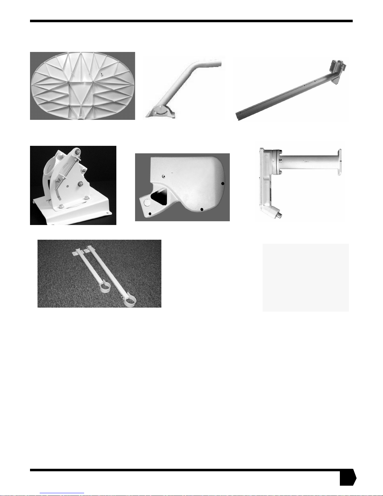
SATELLITE DISH KIT COMPONENTS
YOUR SATELLITE DISH KIT SHOULD INCLUDE THE FOLLOWING ITEMS:
Mast and Base
Satellite Dis h (rear view)
Plate
Feed Arm
Azimuth/Elevation Cap
Shroud
Brace kit
LNB/Waveguide Assembly
Also included are the indoor
items that are necessary to
connect the satellite dish
and your computer. See the
installation guide that comes
with the software and indoor
components (packaged separately in the antenna box)
for a complete list.
PARTS LIST
You r kit al so co ntains a ssorted har dware. Depen ding on how you ins tall an d groun d your syste m, you may have some
hardware left over when you are done. You will have to supply other items. Go to page 4 to view a table that lis ts w ha t y ou w i l l
need to supply .
• M4 Allen screws, Qty: 4
• Red O-ring, Qty : 1
• Galvanized washers, 3/8-inch Qty: 6
• Allen wrench, 3mm, Qty: 1
• Lag scre w s , 1/4-inch x 4-inc h, Qty: 4
• Lag scre w s , 3/8-inch x 2-inc h, Qty: 4
• Lag scre w s , 3/8-inch x 4-inc h, Qty: 6
• 5/16-inch Nyl ock nuts, Qty : 4
• 5/16-inch Lock washer, Qty: 1
• 1/4-20 He x -H ea d Nut, Q ty : 1
• 5/16-18 x 2-inch Hex screw, Qty: 1
• 5/16-18 Wedge nut, Qty: 1
• 5/16-inch F lat washer , Qty: 5
• Galvanized washers, 1/4-inch, Qty: 4
• 1/4-20 x 1/2-inch He x -Hea d Bolt, Qty: 1
• 1/4-inch Lo c k washer (star w asher for
grounding ), Qty: 1
1
Page 6
CON VENTIONS USED IN THIS GUIDE
The following conventions are used throughout this guide to h elp you become familiar with possible safety and equipment hazards.
This safe ty al ert symbol is us ed to a lert you to hazards or
hazardous situ ations that can res ul t in personal injury. A
signal word,
with the alert symbol to indicate the likelihood and
potential se verity of injury.
DANGER
Indicates an immine nt haza rd or unsa f e pr actic e whic h, if
not avoided, will result in death or severe personal injury .
WARNING
Indicates a hazard or unsafe practice which, if not
avoided, could result in death or severe personal injury.
DANGER, WARNING
CAUTION
, or
, is used
CAUTION
Indicates a hazard or unsafe practice which, if not
avoided, might result in moderate or minor personal injury.
CAUTION
When used without the alert symbol, indicates a hazard or
unsafe pr a ctic e that might resu lt in pr op erty dam ag e .
Note: A note pr esents ad ditional informati on.
2
Page 7

A WOR D TO THE DO-IT-YOUR SELF ER
We recommend you ask a professional satellite installer to mount your satellite dish and run your cables, but we recognize that
some people will elect to do their own installation. If you are one of these people, or if you are undecided about whether or not to
perform your own install at i on, please cons i der the following.
• Mounting the satellite dish to a concrete or masonry foundation, exposed deck timber, or metal pole are the best options for the
homeowner because you can see that the fasteners are properly inst alled.
• Mounting the satellite dish t o the house roo f is a desirable mounting method on ly if you are positi ve that you can dril l the holes for
lag screws within 1/16-inch of the center of t he rafters or trusses. Thi s requires s pecial tools and e xpertise. If you mus t mount t o a
roof, pick a location where the roof is unfinished and accessible from the inside so that you can reinfor ce it if necessary and assure
yourself that the fasteners penetrated the rafters or trusses without splintering them.
• Do not depend on consumer quality stud fi nders to locat e rafters underneath asphalt shingl es because the y may gi ve false positiv e
readings or miss rafters entirely.
• Given a choice, it is always best not to penetrate a roof.
• If a lag screw misses the rafter or truss but is securely fastened in the sheathing, the satellite dish could pull the lag screws out of
the sheathing or peel the sheathing aw ay from t he raft er or t russ during hi gh wi nd l oads.
• If you plan to upgrade to a Two-Way System, which requires that the satellite dish be installed by a professional installer, we suggest you revie w the cop y o f its satellite dish installation manual, HNS part number 1031362-0201, on your software installation
CD. The manual can help you understand the Two-Way System installation requi rements.
• When cabling, if there is even a remote possibility that you will upgrade t o either a DIRECTV
extra cables to save yourself future effort.
• If you plan to or think you may upgrade to a Two-Way System, be sure to install your base plate so that its center is 5 feet above
ground.
• Best grounding results are achiev ed with quad shi elded RG6 coaxial cabl e with a shield resist ance of less than 0.6 o hms per 1 00
feet.
• If you install the satellite dish yourse lf , you must su ppl y a num ber of i tems. S ee the f ollo wing t able.
®
system or a T wo-Way System, run
3
Page 8
Type of installation Parts you must supply Tools you must supply
ALL INSTALLATIONS
• Coaxial cable (see “Cable specifications” on
page 9)
• Weatherproof 360° cable connectors
• Cable ties
• Insulated U -sh aped tacks
• F-type ground block and screws
• 1/4-inch washer (fo r grounding if no t u sin g RG-6
quad shielded cable)
• #6 wash er (to help with drilling)
• Silicone sea la nt
• 8AWG aluminum and/or 14AWG copper ground
wire, as required for installation or grounding
scheme
• If not using R G -6 qu ad shield coaxial ca ble, one
split bolt with nut for connections at the ground
block
•Compass
• Angle finder or protr acto r
• Carpenter’s level
• Pencil or chalk
• Ladder or stepladder
• Electric drill
• Ruler and tape measure
• Adjustab l e w r en ch (socket preferred)
• Torque wrench (up to 18 ft.-lb s .)
• Open-end o r s ocket wrenches: 3/16, 1/2, 5/16,
7/16, 9/16-inc h
• Needle-nose pliers
• Lineman pliers
•String
• #2 Phillips or sim il ar screwdriver
• Flat-blade screwdriver
• Hammer
• Permanent marker
Wood post
Wood frame roof
All parts supplied • Drill bits: 3/8, 1/4 , a nd 1/8-inch
• If you decide to use 5/16-inch x 4-inch lag screws
• Drill bits: 3/8, 1/4 , 1/8, and 5/32-inc h
for this i nstallatio n, yo u must p rovid e them and the
5/16-inch galvanized washers
Concrete masonry or
concrete wall
• 3/8-inch x 3 -inc h Hilti sleeve anchor, Qty: 6
• If also insta lling op tional br ace kit, 1 /4- inch x 2 -1/4-
• Hammer drill
• Masonry drill bits: 3/8-in ch
inch Hilti sleeve anchor, Qty: 4
Metal pole
• Metal pole, 2-3/8-inch diameter, 9 feet long,
schedule 40 galvanized
• 1-inch x 2-3/8-inch ground clamp for metal pole
• Hole-digging tools
• Wheelbarro w or co ncret e mixin g bo x
•Hacksaw
• 40-lb. bags quick-setting concrete, Qty: 3
• If not using R G -6 qu ad-shielded cable, one 5/8inch by 10-foot ground rod and ground rod clamp
4
Page 9

INTRODUCTION
N
e
s
e
t
t
This Satellite Dish Insta llation Guide Model: DW 3000 OneWay provides information required to assemble your satellite
dish and establish contact with the satellite.
OTHER USEFUL GUIDES
The installation guide included with the software and indoor
equipment gives an overview of the entire installation process,
including the modem and software installation.
WHAT IS INCLUDED IN THE SATELLITE BROADBAND SYSTEM
The satellite broadband system consists of several major components:
• The receive modem
• The satellite dish assembly that is installed outside
• Cables for connecting the receive mod em and your comp uter
•Software
• This guide and the installation guide included with the software and indoor equipment
This guide is intended for an installer experienced in perfo rming the various installation tasks. Depending on how you will
install the satellite dish, you may be required to:
• Use a power drill to drill holes into your house.
• Locate rafters or trusses and drill holes in the exact center of
them.
• Determine whether there are water pipes, electrical wiring, or
gas lines hidden in the walls near where you wi ll be dril ling.
• Route coaxial cable through the foundation wall, under
floors, and through interior walls.
• Ground the satellite dish and coaxial cable as recommended
in the National Electrical Code (published by the National
Fire Protection Association, Batterymarch Park, Quincy, MA
02269).
If you do not feel comfortable performing these tasks or complying with installation requirements, contact your dealer, or
call 1-866-347-3292 for information on having your system
installed by an authorized professional installer.
BASIC STEPS OF SATELLITE DISH INSTALLATION
To install your satellite dish, follow these basic steps:
1. Install the software and receive modem so that you can
determine pointing values for your sat elli te dis h
2. Choose an installation site
3. Select a mounting method
4. Install the m ount
5. Assemble the satellite dish
6. Install the sa tell ite dish on th e m ount
7. Run cable and ground wire t o connect and grou nd t he entire
assembly
8. Aim the satellite dish
ote: if you think you may later upgrade to th
two-way option (both receive and tr ansmit signal
via satellite), you should at this time install th
antenna assembly in a location or manner no
readily accessible to children and at least 5 fee
above gr ound.
INSTALLATION AND YOUR HOME
The Federal Communications Commission (FCC) has a rule
that generally forbids local governments and homeowners
associations from preventing installation of DBS dishes one
meter or smaller in size (in Alaska, the dish size limit does not
apply). For more information, please visit the FCC’s Web site
at www.fcc.gov. Use the site search engine to find the FCC
F a ct Sh eet on Pl acement of Ant ennas .
5
Page 10

INSTALLING SOFTWARE AND LOCATING THE SATELLITE
Before you can install the satellite dish, you must select an installation site. Before you can select an installation s ite, you must determine the direction you will aim the satellite dish. You determine that dir ection by installing the s ys tem software, which will tell you
the direction.
The satellite is located approximately 22,300 miles in geostationary orbit above the equator. The satellite travels above Earth’s equator from west to east at a speed matching that of Earth’s rotation, thus appearing stati onary in relati on to th e Earth’s surface. To aim
the satellite dish at the satellite, you need to kno w the azimuth, ele vation, and polarization angles. As sho wn in the f igures belo w, you
set the satellite d ish to the correc t azi muth angle by tu rnin g it fr om s ide to side , and s et t he elevation by tilting th e dish up or down.
You set the polarization by rotating the satellite d ish. The polariza tion setti ng rotates the satelli te dish to the corr ect orientation for
your geographic location. This varies from one part of the country to another and is different for different satellites. Polarization is
positive in the eastern United States and negative in the western United States. Remember that it is important to pay attention to positive (+) and ne g a tive (-) signs when recording and using poi nt ing values.
Before you install the satellite dish, the receive modem and software must be installed. To install the software, see the installation
guide that came with your software and indoor equipment fo r specif ic in structions. Aft er you ins tall the modem and softwa re, run t he
software program. It will take you to an Antenna Pointing screen, where you will be asked to enter your location or zip code. The
software will provide the azimu th, el evation, and polarizatio n ang les. W rite them below. The pictures below will help you vis ualize
these terms.
Elevation: Azimuth: Polarization:
Elevation Down
Azimuth Right
Polarization
Positive
Elevation Up
Azimuth Left
Polarization
Negative
6
Page 11
CHOOSING WHERE TO INSTALL THE SATELLITE DISH
TOOLS NEEDED
• Hand-held magnetic compass
• Angle finder or protractor
• Carpenter’s level or straight edge
CAUTION
• Peo pl e can trip, fall into or oth erw ise b um p int o the sat ellite dish.
• Lacerations, bruises, or other impact injuries could
occur .
• Choose an installation site away from where people
are likely to work, ride, or play.
Perform the following steps to select the best site to install the
satellite dish.
1. Go to the location where you plan to install the satellite
dish. It should be a close as possible to the computer, to
minimize the length of the cable run. If the total cable length
required is more than 150 feet see the cable specifications
on page 9.
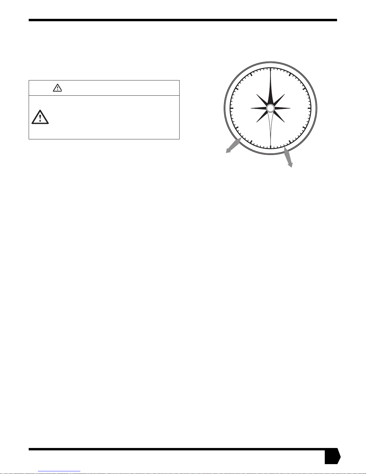
2. Face south and hold the compass level so the needle can
rotate freely. When the needle stops rotating, it will be
pointing north. Carefully, so as not to disturb the needle,
rotate the body of the compass so that the 0° or N mark
printed on the compass aligns with the painted end of the
needle. The compass is now aligned with magnetic north.
Note: Metal near the compass may affect your reading. If you are
standing near a meta l structure, such as a shed or air conditioning
unit, move several feet away and repeat the measurement. Holding the
compass too close to a large metal belt buckle can have the sam e
effect.
3. Draw an imaginary line from the center of the compass to
the azimuth value you recorded on page 6. This is the direction to point the satellite dish. Use a rock or some other
object to mark the location where you are standing. Then
pick a landmark in the distance that aligns with the magnetic azimuth bearing, or mark the azimuth direction in
some other way.
.
300
270
Example 1
225° Azimuth
0
330
N
NW
W
SW
240
210
Figure 1
30
NE
E
SE
S
150
180
Example 2
160° Azimuth
60
90
120
7
Page 12
CHOOSING WHERE TO INSTALL THE SATELLITE DISH
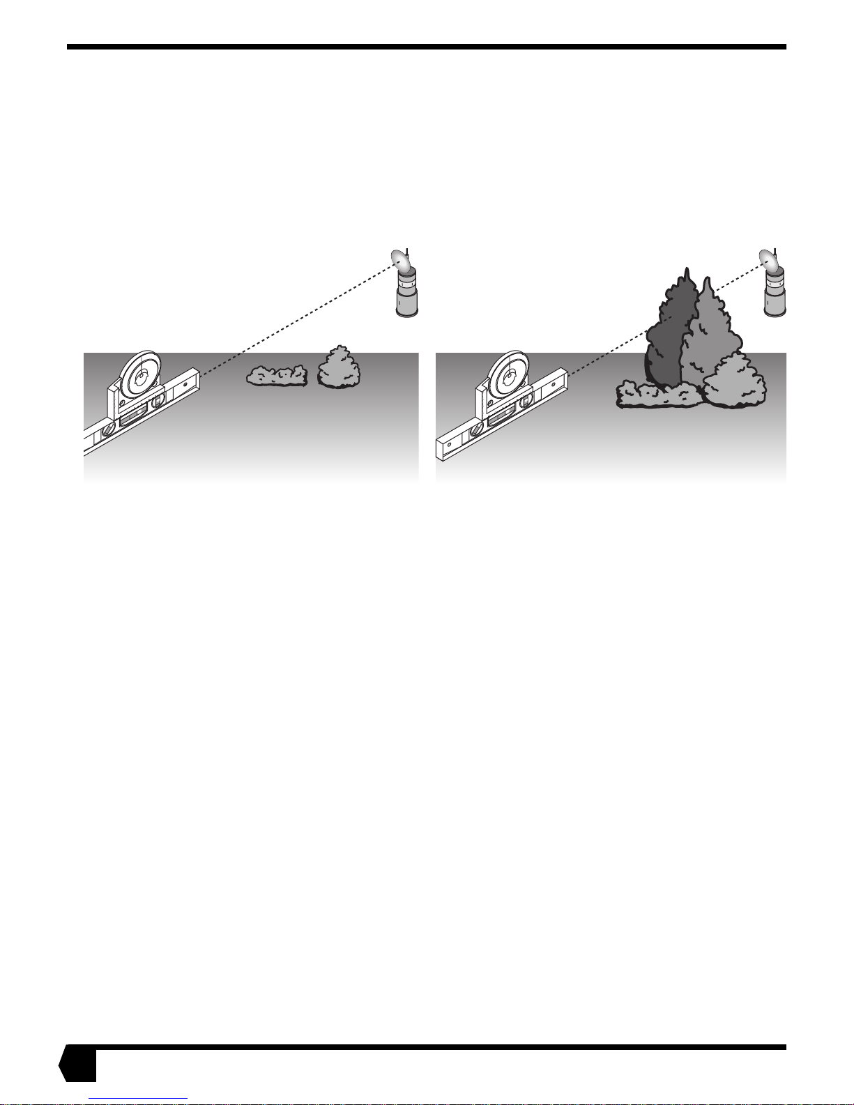
4. Using the angle finder and a carpenter’s level or straight
edge, verify that there is an unobstructed line-of-sight
toward the satellite as shown in the diagram b elow. To do
this, align the level along the azimuth bea ring. Then, using
the angle finder, lift the front end of the straight edge to correspond to the elevation angl e you recorded on page 6. Sight
along the straight edge to verify that there are no obstruc-
Good View
(Clear line-of-sight, no
obstructions in the way)
4
5
0
90
5
4
4
5
90
2 1
0
45
3
2
1
Figure 2
tions (such as buildings or trees) blocking the view. Take
into account future tree growth; if you are installing during
the fall or winter, take into account spring and summer leaf
growth. Also, avoid installing the satellite dish next to electrical equipment such as air-conditioning units, because they
can cause signal interference.
Poor View
(Obstructed line-ofsight, trees are blocking the signal)
4
5
0
90
5
4
4
5
90
2 1
0
45
3
2
1
8
Page 13
CABLE SPECIFICATIONS
Note: Coaxial cables with copper clad steel center conductor are not recommended.
Note: Do not use splitters.
Note: Line amplifiers are required for Receive cable runs of more than 150 ft.
You must use plenum grade cable if the cable is to be run in plenum space which is carrying return air for the air circulation system,
Check local laws to see if plenum grade cable is required in other locations.
If the Receive cable run length is less than 150 ft., then no line amplifier is required. If the Receive cable run length is greater than
150 ft., but less than 30 0 ft., then install a line ampl ifi er in the R ecei ve cable only, a minimum of 25 ft . and up to 30 ft. f rom the LNB.
A line amplifier, if needed, can be installed only in the Receive cable, not in the Transmit cable. (There is no Transmit cable in the
one-way product.)
Line amplifier specification: Channel Master 5113 IF D or equivalent.
Grounding and Cable Choice
Your choice of grounding scheme may affect your choice of cable;
Grounding the Sa tellit e System” on pa ge 31
meeting the National Electrical Code grounding requirements is easier if you use RG-6 with
solid copper center conductor and quad shield. How ever, y o u can als o meet the
requirements by using RG-6 with solid copper center conductor only and g rounding the
mast as described in the Overview.
for information about grounding. Note that
Recommended cable specifications for Two-Way and One-Way Systems
Cable length from sat ellite
dish to computer
Up to 300 ft. RG6 with solid copper
300 ft. to 420 ft. RG6 with solid copper
Important: A higher gra de of cab l e can be used f o r an inst allati on whe re a lo w er gr ade is
specified. Fo r exa mple , an RG6 cab le with sol id copper cent er conducto r and quad shiel d
can be used for installations w here th e c able length is less th an 300 ft. Never use a lower
grade of cable than specified. Be sure to record the grade of the cable used for your
installation. The grade is printed on the cable every few feet. Never use a cable which
does not have the manufacturers name and its grade clearly printed on it!
Type of cable to be used
Receive Transmit
center conductor
(CommScope 5729 or
equivalent)
center conductor
(CommScope 5729 or
equivalent)
see “Overview of
RG6 with solid copper
center conductor
(CommScope 5729 or
equivalent)
RG6 with solid copper
center conductor and quad
shield (CommScope 5781
or equivalent)
9
Page 14
SELECTING A MOUNTING OPTION
Based on the satellite dish installation site, decide on th e best
surface for mounting your satellite dish. The base plate and
mast assembly that came with your satellite dish is called a uni-
versal mount. Some mounting options require only the universal mount. Other mounting options requ ire that you also use
the two struts (called a brace kit) that came assembled with
your satellite dish kit. The struts slip over the mast and provide
addition support.
CAUTION
• Before installing the universal mount brace kit, you
should obtain an analysis from a structural engineer to
confirm that the install ation site is sui table f or mou nting
your sate llite dish using the br a ce kit.
• Failure to ensure that the installation site is capable of
supporting the weigh t o f th e satellite dish c ou ld result
in personal injury or property damage.
CAUTION
The satellite d ish sh ould not be inst alled on a wood fr ame
roof unless the interior of the roof is unfinished so that
placement of la g s crews can be verified and the ro of
reinforc ed if n ec es sa ry.
Note: If you plan to later upgrade your system to two-way (both
receive and tra nsmit signals via satellite), you must install the satellite
dish in a location not readily accessible to children and at least 5 feet
above ground to avoid any risk of harm from radio frequency energy
emitted when transmitting signals to the satellite.
Note: Professional installation of your one-way satellite dish is
strongly r ecommended. I f you do in stall the satellite d ish your self, y ou
must:
• F ollow the in structions in this manual pr e cisely
• Install the satellite dish no higher than 30 feet above grade
• Install the satellite dish only on approved surfaces, and NOT on
any other surfaces
• If necessary, be able to locate wood members from behind the roof
• If necessary, install lag scr ews in the center of wood memb ers
INSTALLING THE SATELLITE DISH ON A WOOD DECK POST
You can use the univ ersal mount to install the satellite dish on a
6-inch x 6-inch Southern Pine wood deck post.
See “Installing The Mount on a Wooden Deck Post” on
page 12.
G-218
Figure 3
INSTALLING THE SATELLITE DISH ON TYPICAL WOOD
ROOF CONSTRUCTION
You can use the universal mount and brace kit to install the satellite dish on typical wood roof construction.
See “Installing the Mount on a Wood Framed Roof” on
page 15.
10
Figure 4
Page 15
SELECTING A MOUNTING OPTION
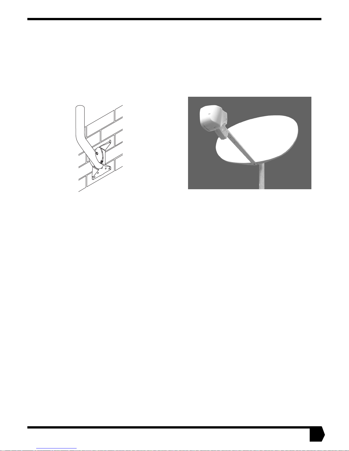
INSTALLING THE SATELLITE DISH ON CONCRETE OR CONCRETE MASONRY WALLS
You can use the universal mount to install the satellite dish on
concrete masonry or concrete walls. The brace kit can also be
installed for greater stability, but is not required.
See “Installing the Mount on Concrete or Concrete
Masonry walls” on page 20.
Figure 5
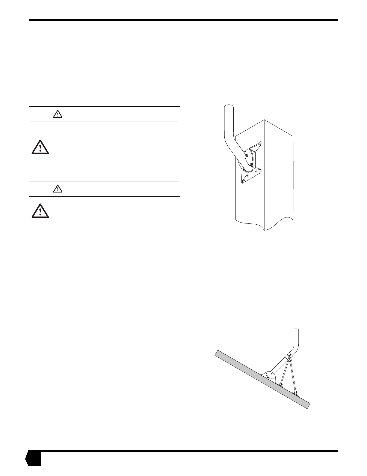
INSTALLING THE SATELLITE DISH ON A METAL POLE
You can install the satellite dish directly on a 9-foot metal pole.
If you choose this mount option you will not need the universal
mount or universal mount brace kit. Store them for possible
future use.
See “Installing the Mount Onto a Metal Pole” on page 22.
Figure 6
11
Page 16

INSTALLING THE MOUNT ON A WOODEN DECK POST
The satellite dish can be installed on a 6-inch x 6-inch Southern Pine wood deck support post. The post can be no more than 8 feet
tall. It must be adequately attached at top and bottom. Posts made of other species of wood may be used as long as their material
properties match or exceed those of Southern Pine. Posts made of other species of wood whose material properties do not match or
exceed those of Southern Pine require engineering evaluation and approval before being used. The satellite dish may not be installed
on an unsupported wooden po st.
PARTS NEEDED TOOLS NEEDED
• Lag screws, 3/8-inc h x 4-inch, Qty: 6
• W a sh ers, 3/8-inch, Qty: 6
• Silicone se alant
• Carpenter’s level
• P e ncil
• Ruler
• 9/16 and 1/2-inch socket wrench
• Electric drill
• Drill bits, 3/8, 1/4, and 1/8-inch
• Torque wrench
up to 18 ft-lbs)
• Ladder
(capabl e o f t orq ui ng
12
Figure 7
Page 17

INSTALLING THE MAST ONTO A W OODEN DEC K POST
INSTALLATION PROCEDURE
DANGER
• If the sat elli te d ish contacts electric power lines, y o u
will be killed or s eriou sly injured.
• Before starting the installation procedure, make sure
there are no power lines nearby.
CAUTION
• The satellite dish cannot be installed on an unsupported wood post of any size.
• Install the satellite dish only on a w o od en deck post.
• Install the satellite dish only as described in this man -
ual.
Note: for an installation to be successful, the mast must be plumb. Replumb the mast wheneve r in str ucted to do so, an d re-plumb it whenever you feel it is necessary .
1. Orient the universal mount so the square hole in the base
plate is at the top as in Figure 8 before installation.
2. Use a 1/2-inch socket wrench to loosen the adjustment nuts
and swing the mast so that it is oriented as in Figure 9.
3. Mark the centerline of the deck post.
4. W ith an assistant place the base plate on the centerline at the
spot you plan to install it (see Figur e 8).
5. Loosen the pivot bolt and adjustment nuts and plumb the
mast in two perpendicular directions (see Figure 9). If you
successfully plumb the mast proceed to s tep 6. If yo u cannot
plumb the mast find another locat ion to install the satellit e
dish. Note: it is essential that the mast be plumb. If you can-
not make the mast plumb at this point, f i nd another ins tallation site.
6. Mark the center of the base plate’s top center hole.
7. Drill a hole on the center mark in the manner described
below. Note: to avoid drilling too deeply, wrap a piece of
masking tape around the drill bit shank at the proper depth
so that you can see when you should stop d ri lling.
Drill a 1/8-inch pilot hole 2 inches deep.
Going into the pilot hole, drill a 1/4-inch hole 4 inches deep.
Going into the 1/4-inch hole, drill a 3/8-inch hole to a depth
equal to the unthreaded portion of the 3/8-inch x 4-inch lag
screw.
8. Fill the holes with silicone sealant and apply silicone sealant
to the entire back side of the base plate. Apply enough so
that it will press out around the edges when it is fastened
down (see Figure 10). Doing this will help prevent water
from seeping into the wood.
Top left center
All lag screws
3/8-inches x 4-inches
Bottom left center
Carpenter's level
Plumb vial
Bubble
Bubble must
be centered
between
marks
Mast
Pivot bolt
Adjustment nut
(2 places)
Sealant
Top
Bottom
Figure 8
Figure 9
Top right center
Top center
Center line
Bottom center
Bottom right
center
Mast
(top view)
Level
G-21848
11/16/00
Figure 10
13
Page 18

INSTALLING THE MAST ONTO A W OODEN DEC K POST
9. Install a 3/8-inch w as her on a 3/8-inch x 4- inch lag s crew.
10. Use a 9/16-inch socket wrench to screw the lag screw into
the top center hole of the base plate (see Figure 11). You
may need to swing the mast out of the way temporarily.
Tighten the screw snugly so that the base plate can barely
move.
Do not pound the lag screws into the post with a hammer or mallet.
Doing so may split the wood and r ender the post unus able.
11. Re-plumb the mast in two perpendicular directions as you
did in step 5. You may need to make adjustments to the mast
and/or the base plate.
12. Tighten the lag screw snugly s o that the base canno t move.
13. Use a 1/2-inch socket wrench to tighten the adjustment nuts.
14. Re-plumb the mast. (Tightening the nuts can move the mast
off plumb.) Note: the mast must be plumb before proceed-
ing.
15. Repeat step 6 and step 8 to drill holes for the top left center,
top right center, bottom left center, and bottom right center
holes. See Figure 11.
Note: You must mark the center of all remaining screw holes
accurately. A Stanley Jumbo Self Centering Nail Set or similar
product will produce the best results. A #6 washer can also be
used to guide your pencil as it marks the hole center
Note: the base plate must not move when you drill the holes.
16. Fill the holes with silicone sealant.
17. Install a 3/8-inch washer on each of the 3/8-inch x 4-inch
lag screws.
18. Use a 9/16-inch socket wrench to screw the lag screw into
the four holes. Do not tighten the screw s f ully.
19. R e-plumb th e mast and snu g down the four screws firmly.
20. Use a 1/2-inch socket wrench to loosen the mast adjustment
nuts and swing the mast down so you hav e access t o the bot tom center hole.
21. Repeat steps 6 and 7 to drill holes for the bottom center
hole.
Note: the base plate must not move when you drill the hole.
22. Fill the hol e with silicone s ealant .
23. Install a 3/8-inch washer on the final 3/8-inch x 4-inch lag
screw.
24. Use a 9/16-inch socket wrench to screw the lag screw into
the lower center hole. Do not tighten the screw fully.
25. R e-plumb th e mast and snu g down the lag screw.
26. Use a torque wrench to sung down t he mast ad just ment nuts
to 18 ft.-lbs. Confirm the mast is pl umb afte r torqui ng.
Note: The mast must be plumb before you can proceed. If you cannot
plumb the mast, repeat the installation or find another installation site.
Continue with section “I nstalling the Cap O nto the Satellite
Dish” on page 23.
Top left center
All lag screws
3/8-inches x 4-inches
Bottom left center
Top
Bottom
Figure 11
Top right center
Top center
Center line
Bottom center
Bottom right
center
14
Page 19

INSTALLING THE MOUNT ON A WOOD FRAMED ROOF
You can install the satellite dish onto a wood framed roof. You must use the brace kit. The minimum size for roof truss members is 2
inches x 4 inches. Roof rafters must be nominal 2x material (2x4, 2x6, etc.) Either size roof rafters or trusses must be16 t o 24 inches
on center. The roof surface must consist of relatively thin, resilient materials, such as asphalt or composite shingles, sheet metal, or
similar materials, over wood sheathing with a thickness of 3/4 inch or le ss. Satellite dishes cannot be installe d on flat roofs, slate
roofs, or Spanish tile roof ing made of cl ay or other bri t tle materials. The roof pitch (or slope) must be between 3:12 and 12:12.
All center hole lag screws must be centered in the rafter or truss to which they are attached. For this reason, you must be able to
locate rafters and trusses and the center of rafters and trusses with a high degree of accuracy, which can be difficult to do. Home construction varies a great deal. Construction styles, materials, and dimensions can all vary widely. In addition, stud finders give false
readings on multilayered surfaces, such as a roof. Also, you need experience in home construction to be able to determine the exact
location of rafters and trusses and their centers. The satellite dish should not be installed on a wood frame roof unless the interior of
the roof is unfinished so that placement of lag screws can be verified and the rafters or trusses reinforced if necessary.
If you do not have the knowledge and experience to accurately locate rafters and trusses and the center of rafters and trusses with a
high degree of re liabi lit y, you should contact a p rofessional satellit e di sh i ns talle r f or inst allat ion.
Large-timber roofs with frequent spacing of members are also permitted. These are constructed of wood members larger than the
nominal 2x sizes, and include post and beam structures with members from 4 inches x 4 inches and larger. The members cannot be
spaced more than 24 inches on center. Their phy sical properties must match or exceed those of Spruce-Pine-Fir #2.
PARTS NEEDED TOOLS NEEDED
• Lag screws, 3/8-inc h x 4-inch, Qty: 2
• Lag screws, 1/4-inch x 4-inch, Qty: 4 (5/16-inch x
4-inch recommended if available)
• Lag screws, 3/8-inc h x 2-inch, Qty: 4
• W a sh ers, 3/8-inch, Qty: 6
• Washers, 1/4-inch, Qty: 4 (5/16-inch if needed)
• Silicone se alant
• Carpenter’s lev el
• Pencil or chalk
• Ruler
• Socket wrenches, 7/16, 1/2, and 9/16-
inch
• Electric drill
• Drill bits, 3/ 8- , 1/ 4-, 1/8, and 5/32-in ch
• Torque wrench (can torqu e u p to 18 ft-
lbs)
• Ladder
Figure 12
15
Page 20

INSTALLING THE MOUNT ON A WOOD FRAMED ROOF
Corner holes
Corner holes
Top center hole
Bottom center hole
Centerline
Rafter or truss
0
INSTALLATION INSTRUCTIONS
DANGER
• If the sat elli te d ish contacts electric power lines, y o u
will be killed or s eriou sly injured.
• Before starting the installation procedure, make sure
there are no power lines nearby.
CAUTION
• Rafters or truss es m u st be located 16 to 24 inch e s
apart on center, except for large-timber ro ofs, which
can be located no m or e th an 24 inches apart on center.
• The roof surface must consist of relatively thin, resilient
materials, such as asphalt or composite shingles,
sheet metal, or sim ila r m a te rials , over woo d sh ea thin g
with a thickn es s that must not exceed 3/4 inch .
• Satellite dishes cannot be installed on slate roofs or
Spanish tile roofing made of clay or other brittle materials.
• The roof pitch (also called slope) must be between
3:12 and 12:12.
• The sat elli te dish cannot be installed on a flat ro of.
• Center hole lag screw s
or truss.
• The satellite dish should not be installed on a wood
frame roof un les s the interior is unfinis he d so that
placement of la g s cr ews can be verified and the roof
reinforced if n ec es sa ry.
• Install the satellite dish only as described in this man ual.
must
be centere d in t he rafter
.
Carpenter's level
Plumb vial
Bubble
Bubble must
be centered
between
marks
Mast
Pivot bolt
Center hole lag
screws are 3/8 inches
by 4 inches
Corner lag screws
are 3/8 inches
by 2 inches
Figure 13
Mast
(top view)
Level
CAUTION
If you do not have the knowledge and experience to
accurately loc ate rafters and the ce nte r o f rafters with a
high degree of re liability, you should contact a prof essiona l
satellite dish install er f or insta llation .
Before you begin, make sure the rafters or trusses (called members) in your house are located 16 to 24 inches on center.
Remember that 2 x 4 and 2 x 6 inch members are actually
1-1/2 inches thick.
Note: for an installation to be successful, the mast must be plumb. Replumb the mast wheneve r in str ucted to do so, an d re-plumb it whenever you feel it is necessary .
1. Orient the universal mount so the square hole in the base
plate is at the top as in Figure 13 before installation.
2. Use a 1/2-inch socket wrench to loosen the adjustment nuts
and swing the mast so that it is oriented as in Figure 14.
3. Mark the centerline of the rafter or truss.
16
Adjustment nut
(2 places)
T0
Figure 14
Page 21

4. W ith an assistant place the base plate on the centerline at the
Corner holes
Corner holes
Top center hole
Bottom center hole
Centerline
Rafter or truss
s
0
spot you plan to install it (see Figur e 15).
5. Plumb the mast in two perpendicular directions (Figure 16).
If you successfully plumb the mast proceed to step 6. If you
cannot plumb the mast find another location to install the
satellite dish. Note: it is ess ential th at the mas t be plumb. If
you cannot make the mast plumb at this point, find another
installation site.
6. Mark the center of the base plate’s top center hole
(Figure 15).
7. Drill a hole on the center mark in the manner described
below.
Note: to avoid drilling too deeply, wrap a piece of masking tape
around the dr ill bi t sh ank at the proper depth so tha t you can see
when you should stop drilling .
Drill a 1/8-inch pilot hole 2 inches deep.
Going into the pilot hole, drill a 1/4-inch hole 4 inches deep.
Going into the 1/4-inch hole, drill a 3/8-inch hole to a depth
equal to the unthreaded portion of the 3/8-inch x 4-inch lag
screw.
Note: You must mark the center of all screw holes accurately. A Stanley Jumbo Self Centering Nail Set or similar
product wi ll produce the best r e su lts. A #6 was her can al s o
be used to guide your pencil as it marks the hole center.
8. Apply silicone sealant in the holes and to the entire back
side of the base plate. Apply enough so that it will press out
around the edges when the plate is fastened down.
9. Install a 3/8-inch w as her on a 3/8-inch x 4- inch lag s crew.
10. Use a 9/16-inch socket wrench to screw the lag screw into
the top center hole of the base plate (see Figure 15). You
may need to swing the mast out of the way temporarily.
Tighten the screw snugly so that the base plate can barely
move.
Note: Do not pound the lag scre ws into the rafter or truss with a hammer or mallet. Doing so may split the wood and render the rafter or
truss unusable.
11. Re-plumb the mast in two perpendicular directions as you
did in step 5. You may need to make adjustments to the mast
and/or the base plate. If you adjust the base plate, do not
move the center of the bottom center hole off the centerline
more than 1/16-inch.
12. Tighten the lag screw snugly s o the base pl ate cannot move.
13. Use a 1/2-inch socket wrench to tighten the adjustment nuts.
14. Re-plumb the mast. (Tightening the nuts can move the mast
off plumb.) Note: the mast must be plumb before proceed-
ing.
15. Adjusting the drilling depth for the 3/8-inch by 2-inch lag
screws, repeat steps 6 and 7 to drill holes for the four corner
holes. See Figure 15.
Note: the base plate must not move when you drill the holes.
INSTALLING THE MAST ON A WOOD FRAMED ROOF
Carpenter's level
Plumb vial
Bubble
Bubble must
be centered
between
marks
Mast
Pivot bolt
Adjustment nut
(2 places)
Center hole lag
screws are 3/8 inche
by 4 inches
Corner lag screws
are 3/8 inches
by 2 inches
Figure 15
Mast
(top view)
Level
T0053
Figure 16
17
Page 22

INSTALLING THE MOUNT ON A WOOD FRAMED ROOF
16. Fill the holes with silicone sealant.
17. Install a 3/8-inch washer on each of the 3/8-inch x 2-inch
lag screws.
18. Use a 9/16-inch socket wrench to screw the lag screw into
the four holes. Note: do not overtighten the screws. You may
strip the screw threads.
19. R e-plumb th e mast and snu g down the four screws firmly.
20. Use a 1/2-inch socket wrench to loosen the mast adjustment
nuts and swing the mast down so you hav e access t o the bot tom center hole.
21. Repeat steps 6 and 7 to drill holes for the bottom center
hole. Note: the base plate must not move when you drill
the hole.
22. Fill the holes with silicone sealant.
23. In stall a 3/8-inch w asher on the 3/8-i nch x 4-inch lag screw.
24. Use a 9/16-inch socket wrench to screw the lag screw into
the lower center hole. Do not tighten the screw fully.
25. R e-plumb th e mast and snu g down the lag screw.
26. Use a torque wrench to sung down t he mast ad just ment nuts
to 18 ft.-lbs. Confirm the mast is pl umb afte r torqui ng.
Note: The mast must be plumb before you can proceed. If you cannot
plumb the mast, repeat the installation or find another installation site.
Figure 17
INSTALLING THE BRACE KIT
1. Slip the short 18-inch strut coll ar ont o the mas t as sh own in
Figure 17.
2. Secure the collar to the mast by using a 7/16-inch socket
wrench to tighten the Nylock nut installed on the bolt.
3. Position the strut mounting plate below the mast and base
plate so the two screw holes are exactly in line vertically
with the mast base plate center holes (see Figure 18).
4. Mark the center of the mounting plate top center hole (see
Figure 17).
5. Drill a hole on the center mark in the manner described
below. Note: to avoid drilling too deeply, wrap a piece of
masking tape around the drill bit shank at the proper depth
so that you can see when you should stop d ri lling.
Drill a 5/32-inch hole 4 inches deep.
Going into the 5/32-inch hole, drill a 1/4-inch hole to a
depth equal to the unthreaded portion of the 1/4-inch x
4-inch lag screw.
6. Fill the holes with silicone sealant, and apply silicone sealant to the bottom of the mounting plate.
7. Install a 1/4-i nch washer on the 1/ 4-inch x 4-inch lag screw .
8. Use a 7/16-inch socket wrench to screw the lag screw into
the mounting plate hole. Note: Do not pound the lag screws
into the rafter with a h ammer or malle t. Do ing s o ma y sp li t
the wood and damage the raf ter or t ru ss.
Center line
Top center hole
Bottom center hole
Figure 18
18
Page 23

INSTALLING THE MOUNT ON A WOOD FRAMED ROOF
9. Detach the strut from the mounting plate and repeat step 5
through step 9 for the lower center hole. Reattach the strut
when done.
10. Secure the collar to the mast by using a 7/16-inch socket
wrench to tighten the Nylock nut installed on the bolt.
11. Re-plumb the mast.
12. Slip t he long 25 -in ch strut collar o ver the mast until it fits as
shown in Figur e 19.
13. Position the strut so that its mounting plate center holes are
on center of the rafter immediately to the left (or to the right
if you prefer). The 25-inch strut should be at approximately
a 90° angle to the 18-inch strut. At the same time, minimize
any angle formed between the 25-inch strut and the centerline of the mast base plate (see Figure 19).
14. R epeat step 4 t hrough s tep 10 for the 25-inch st rut mounti ng
plate.
15. R e-plumb the mast . If you had to l oosen the adjust ment nuts
to plumb the mast, snug them again to 18 ft.-lbs.
Note: The mast must be plumb before you can proceed. If you cannot
plumb the mast, repeat the steps above or find another installation
site.
Continue with section “I nstalling the Cap O nto the Satellite
Dish” on page 23.
Figure 19
19
Page 24

INSTALLING THE MOUNT ON CONCRETE OR CONCRETE MASONRY WALLS
The satellite dish can be attached to concrete masonry (cinder blocks) or concrete walls. The concrete masonry (cinder block) or concrete walls must be a minimum of 8 inches thick. Attachment anchors can be placed no closer than 12 inches from any discontinuous
surface, such as a window, door, or edge of a wall. Anchors can not be installed in mortar joints or within 2 inches of mortar joints.
You must use the specified Hilti sleeve anchors. Ins tall onl y the si x anchors speci f i ed; do not install additional anchors.
The satellite dish cannot be installed on masonry veneered wall construction or on any synthetic stucco wall surface (also called
Exterior Insulation and Finish Systems (EIF S).
Note that you can use the brace kit to improve the mount’s stability if you wish. If you use the brace kit, do not install the strut mounting plates within 12 inches of any discontinuous surface, such as a window, door, or edge of a wall. Its anchors must be tightened to
5 ft.-lbs.
PARTS NEEDED TOOLS NEEDED
• 3/8-inch x 3-inch Hilti sleeve anchors, Qty: 6
• If installin g th e optional brace k it, 1 / 4- inc h by
2-1/4-inch Hilti sleev e anchors, Qty: 4
• Ladder
• Carpenter’s level
• Pencil
• Tape measure
• Hammer
• Hammer drill
• Masonry drill bits, 3 /8-in ch (a nd 1/4 -inch
if needed)
• Wrench, 9/ 16 and 1/2-in ch or ad justab l e
(1/4-inch if needed)
• Torque wrench (up to 18 ft-lbs )
• Blow out air bulb
20
Figure 20
Page 25

INSTALLING THE MOUNT ON CONCRETE OR CONCRETE MASONRY WALLS
n
8
/
INSTALLATION PROCEDURE
DANGER
• If the sat elli te d ish contacts electric power lines, y o u
will be killed or s eriou sly injured.
• Before starting the installation procedure, make sure
there are no power lines nearby.
CAUTION
Corner holes
Top center hole
Cinder block
or concrete
2 in.
min.
A
• Attach the satellite dish only to concrete masonry (cinder blocks) or concrete walls at least 8 inches thick.
• Do not attach the satellit e dish to stu cco or to maso nry
veneered surfaces.
• Do not ins tall anchors within 12 in ch es from any discontinuous surf ace, su ch as a w indow, door, or ed ge of
a wall.
• Anchors ca n not be insta lled in mortar joints or within 2
inches of mortar joints.
• Install the s atellite dish only as d es cribe d in th is manual.
Do not drill holes within 12 inches of any discontinuous surface such as a window, door, or edge of a wall. Note: for an
installation to be success ful, the mast must be plumb. Re-plumb the
mast whenever i nstru cted to do so , and re-plumb it whene ver y ou fe el
it is necessary .
1. Orient the base plate as in Figure 21.
2. Place the base plate so that no anchor will be placed closer
than 12 inches from any discontinuous surface, such as a
window, door, or edge of a wall. If you are installing on a
cinder block surface, place it so the outside holes are positioned over the block surfaces. Do not drill into the mortar
between the blocks or closer than 2 inches to any mortar
joints. If you plan to install the brace kit, consider placement
of the strut mounting pl ates at this t ime a lso.
3. Hav e a helper hold the mast and base plate in place. Using a
carpenter’s level, plumb the mast in at least two different
locations on the side of the mast (see Figure 21). These two
measurements should be at right angles to each other. If the
mast is plumb, go to step 5. Otherwise, use a 1/2-inch socket
wrench to loosen the adjustment nuts.
4. Swing the mast until it is plu mb with the level. If you are
still unable to plumb the mast, find another site to install the
satellite dish.
Note: It is essential that the mast be plumb. If you cannot make the
mast plumb at this point, f in d anoth er inst allat ion sit e.
Note: If you loosen the adjustment nuts at any poi nt during installation so that you can move or plumb the mast, be sure to tighten them
snugly after re- plumbing the ma st.
5. Mark the location of the top center, bottom center, and four
corner holes of the base plate onto the concrete surface
(Figure 22). Remove the mount from the wall.
Mortar
Bottom center hole
Corner holes
Figure 21
Carpenter's level
Plumb vial
Bubble
Bubble must
be centered
between
marks
Mast
Pivot bolt
Adjustment nut
(2 places)
Mast
(top view)
Level
G-21
11/16
Figure 22
6. Use a 3/8-inch masonry dril l bill and dri ll 3/8-inch x
3-inch holes where you made the pencil marks. Clean out
the holes with a blow out bulb.
7. With the bolts flush to the top of the nuts, tap the sleeve
anchors to drive them into the holes.
8. Using a 9/16-inch wrench, remove the bolts from the
anchors.
9. Place the mount back on the wall, carefully centering the
base plate holes over the holes you just drilled.
10. Plumb the mast.
11. Using a torque wrench, reinstall the anchors, tightening
them to 10 ft. lbs.
12. Verify the mast is still plumb and tighten t he two adjus tment
nuts to 18 ft.-lbs.
21
Page 26

INSTALLING THE MOUNT ONTO A METAL POLE
a
a
a
a
a
a
a
a
aa
aaa
a
a
a
a
a
a
a
aa
The satellite dish can be installed on a metal pole that you place in the ground. With this option, you will attach the dish and cap
mount directly to the pole. Note: With a metal pole installation, you w ill n ot n eed the ma st a nd ba se pl ate incl uded in you r sa te llite
dish kit. Store it fo r pos sibl e fu ture use.
PARTS NEEDED TOOLS NEEDED
• Metal pole , 2-3/8 inch o utsid e diamet er, schedule 40 galvanized
water pipe, 9 feet lo ng
• Three 40-pound bags of quick-setting concrete
DANGER
• If the sat elli te d ish contacts electric power lines, y o u
will be killed or s eriou sly injured.
• Before starting the installation procedure, make sure
there are no power lines nearby.
DANGER
• Call local utility companies before digging to avoid
striking undergroun d cab l es , pipes , or lines .
• Striking or cutting under gro und cab l es , pipe s, or line s
can cause pers onal injury or property damage .
1. Use the hacksaw to cut the bottom edge of the pole at a 45degree angle (see Figure 23). This will prevent the pole
from rotating over time.
2. Dig a hole at least 8 inches in diameter and at least 36
inches deep (see Figure 24). If you live in an area where the
frost line goes below 30 inches, dig the hole at least 6 inches
deeper than the frost line.
3. Place the bottom 3 feet of the pole in the hole and use rocks
or similar objects to stabilize the pole vertically.
4. With the carpenter’s level, plumb the pole along its side.
Use at least two different locations at right angles to each
other (see Figure 25).
5. When the pole is plumb, use rocks or guy wires and stakes
to hold it in place.
Note: In order for the installation to be successful, the pole must be
plumb. Mak e sur e the pole is securely held in place while the concr ete
is drying.
6. Confirm the pole is still plumb and adjust if necessary.
7. Prepare the quick-drying concrete according to directions
on the package and fill the hole. Slope the top of the concrete downward away from the pole to impro v e drainage.
8. Let the concrete dry for 24 hours.
Continue with section “I nstalling the Cap O nto the Satellite
Dish” on page 23.
• Hole digg in g t oo l s
• Wheelbarrow or concrete mixing box
• Carpenter’s lev el
Cut this section from the pole
Figure 23
Metal post
8 inches
mínimum
Figure 24
Carpenter's level
Plumb vial
Bubble
Bubble must
be centered
between
marks
Pole
Pole
(top view)
Level
• Pencil
• Hacksaw
Pole
10-inch to 2-inch
slope for water run-off
Grade
36 inches
mínimum
6 inches below
frost line
Figure 25
22
Page 27

INSTALLING THE CAP ONTO THE SATELLITE DISH
PARTS NEEDED TOOLS NEEDED
• Azimuth/Elevation (AZ/EL) cap assembly
• Satellite dish
• 5/16-inch Nylock nuts,
You will set the satellite dish elevation and polarization, which
you wrote down in this manual on page 6, before attaching the
azimuth/elevation (AZ/EL) cap to the satellite dish. As you set
them, refer to Figure 26. Note the cap has an arrow, labeled
“Top,” to show you how to orient the cap vertically. See
Figure 29 on page 24.
1. Use a 1/2-inch socket wrench or open-end wrench to loosen
the four polarization nuts.
2. Refer to page 6 of this manual to find the elevation value.
3. Orient the cap assembly so that the “TOP” label is at the
upper right. The elevat i on bolt will also be on t he right.
4. Use a 1/2-inch socket wrench or open-end wrench to loosen
the AZ/EL bracket bolt nut and elevat ion nut s .
5. Using your fingers, retighten the three nuts until you cannot
tighten them further.
6. Still using your fingers, loosen each of the nuts one revolution.
7. Locate the red elevation reference mark on the elevation
scale on the left side of the cap assembly. See Figure 27 and
Figure 28 on the next page to help you locate the mark. The
Qty: 4
• 5/16-inch f lat washers
Qty: 4
• 7/16-inch open-end wrench or socket wrench
• 1/2-inch open-end wrench or socket wrench
• Torque wrench (can accept 1/2-inch socket and
exert 12 ft-lbs. of torque)
leading edge of the metal plate is the elevation reference
mark.
8. Use a 1/2-inch socket wrench or open-end wrench to turn
the elevation bolt head until the leading edge of the red
mark is at the correct value. You may need to turn the bolt
head a number of times until the leading edge of the red
mark reaches the correct value.
9. When the leading edge of the red mark is at the correct e levation value, tighten the bracket bolt nut and the two elevation nuts. Do not tighten the elevation pi v ot nut.
10. Refer to page 6 to find the polarization value.
11. Locate the polarization scale. It is at the top of the AZ/EL
cap (Figure 29).
12. Turn the AZ/EL to the correc t polarizatio n value. Align the
mark on the top of the AZ/EL with the correct value on the
polarization scale. Figure 29 shows a setting of positive 3
degrees.
13. When the polarization is at the correct value, tighten the
four polarization nuts. As you tighten, make sure the polarization remains at the proper value.
Figure 26
Bracket bolt nut
Elevation bolt head
Elevation bolt
Clamp bolts (3)
Elevatio n pivot
Polarizati on sc ale
TOP label
Polarization nuts (4)
Elevation nuts (one each side)
23
Page 28

INSTALLING THE CAP ONTO THE SATELLITE DISH
Read the leadi
Thi
14. Place the AZ/EL cap over the studs sticking out from the
back of the satellite dish (see Figure 30). Make sure the
AZ/EL cap mount bolt holes are properly aligned with the
studs. The elevation bolt should be on the right, and that the
arrow labeled “TOP” should point to the top of the satellite
dish. Make sure the sa tellite di sh is orien te d so th at the s ection that has a hole in its rim is on the bottom.
15. Install four 5/16-inch Nylock nuts and 5/16-inch flat washers on the studs. Use a torque wrench with 1/2-inch socket
to torque to 12 ft.-lbs.
ng edge of the red elevation mark.
picture shows the elevation set to 34°.
Figure 28
s
Elevation Reference Mark
Figure 27
Figure 29
Figure 30
24
Page 29

INSTALLING THE LNB/WAVEGUIDE
PARTS NEEDED TOOLS NEEDED
• LNB/W aveguide ass embly
• M4 Allen screws, Qty: 4
• M4 Lock w ash ers, Qty: 4
1. Facing the front of the feed arm, locate the red mark on the
right side of the rectangular section with four holes (see
Figure 31).
2. Install the O -ring in the circular depression in the fee d arm
(see Figure 32.) Note that the circular depression contains
four small depressions at 12, 3, 6, and 9 o’clock. These are
pinch points. Be sure t o push th e O-ring i n at these point s to
achieve a better seal.
3. Orient the LNB/waveguide so that the flat side of the LNB
faces your body, and the red mark is on the right (see
Figure 33).
4. Line up the feed arm rectangular section with the waveguide
so that the four screw holes align. The tw o red marks should
be on the same side but may or may not align exactly. Use
the red marks as guides. What is important is that the four
screw holes align (see Figure34).
5. Install the M4 Allen screws and lock washers with the Allen
wrench that is provided.
• Feed arm
• O-ring
• Allen wrench (supplied)
Figure 32
Red mark
Figure 31
LNB
Waveguide
Figure 33
Red Mark
Figure 34
25
Page 30

CONNECTING THE FEED ARM TO THE SATELLITE DISH
PARTS NEEDED
• Fe ed arm w ith feed assembly (LNB and w aveguid e) attached
• Satellite dis h
• 5/16-18 wedge nut
• 5/16-18 hex bolt
• 5/16-inch f lat washer
• 5/16-inch l ock washe r
TOOLS NEEDED
• 1/2-inch open-end wren ch or socket wrench
• Torque wrench (with 1/2-inch socket capable of torquing to 10 ft-
lbs.)
Note: Be sure that the feed arm and feed assembly are positioned as
shown in Figure35.
Note: If you are installing the satellite dish assembly on a metal pole
mount, it is probably easiest to attach the feed arm after you have
installed the satellite dish on the pole. See “Installing the satellite
dish/cap assembly onto the mast ” on page 27.. However, if you are
using a ladder, it may be easier to attach the feed arm to the satellite
dish before installing it on the mast or metal p ole.
1. Insert the 5/16-18 wedge nut thin end first into the slot provided on the back of the satellite dish. The wedge nut is
keyed so that it will fit properly in its slot in the dish in only
one way. Make sure the hole in the wedge nut is aligned
with the hole in the dish so the bolt can be installed (see
Figure 35).
2. Install the feed arm into the feed support socket on the
underside of the satellite dish. Since you may have the satellite dish turned upside down in order to insert the feed arm,
take care to remember that your orientation is currently the
opposite of that shown i n Fi gur e 35.
3. Secure the feed arm with a 5/16-inch flat washer, 5/16-inch
lock washer, and 5/16-18 hex bolt. Use a torque wrench to
tighten the hex bolt 8 to 10 ft-l bs.
Antenna dish
5
/
-18 wedge nut
16
Feed arm
5
/
-inch flat washer
16
5
/
-inch lock washer
16
5
/
-18 hex bolt
16
Wedge nut
Figure 35
26
Page 31

INSTALLING THE SATELLITE DISH/CAP ASSEMBLY ONTO THE MAST
PARTS NEEDED TOOLS NEEDED
• Satellite d is h/c ap as se m bly
• Mast
1. Lightly grease the area at the end of the mast or metal pole
that will be covered by the AZ/EL cap. Doing this ensures it
will be easy to adjust the azimuth. Any grease will do. You
can use automotive grease, or household grease such as
Vaseline or lard.
2. Use a 1/2-inch open-end w rench to loosen the three clamp
nuts so the collar will be able to slide over the mast or metal
pole.
To satellite
• 1/2-inc h o p en-end wrench
• Grease
3. Lift the satelli te dish/cap assembly and slide the AZ/EL cap
collar onto the mast tube or metal pole (see Figure 36). The
satellite dish should be facing toward the satellite.
4. Tighten the three mast clamp nuts all the way; then loosen
them just enough to move the satellite dish side to side and
adjust the azimuth. The clamp bolts should be as snug as
possible, but still allow the satellite dish to be moved from
side to side.
Mast or metal pipe
Figure 36
Clamp bolt nuts (3)
Place AZ/EL cap over
mast or metal pipe
27
Page 32

INSTALLING AND ROUTING INTERIOR CABLE
PARTS NEEDED TOOLS NEEDED
• RG-6 coaxial cable
• Cabl e ties
• Silicone se alant
• 14 AWG copper/8 A WG aluminum
grounding wi re
This section consists of routing a coaxial cable from the outside wall into your house to the receive modem connected to
your computer. In most installations, there is more than one
way to get the cable to its inside destination. If the receive
modem is located near an inside wall, you can use the crawl,
basement, or attic spaces. Use cable ties where necessary.
When routing the cable to the receive modem, take the shortest
possible path and always protect it from physical damage. You
may need to feed a length of string through tight access hole(s)
and then pull the cable through.
It is important to remember that each cable is actually installed
in two sections. One section runs from your receive modem to
the ground block, which is installed where the cable exits the
house. The other section runs from the ground block to the
LNB.
Cable is usua lly sold in lengths of 100, 75, 50 , and 25 fee t. If
the distances between your receiver and ground block, or
ground block and antenn a, are not appr oximatel y thos e lengths ,
you may have to cut and strip the cable and install the weatherproof connectors.
Remember that you must use 14 AWG copper grounding wire
if the ground wire will come within 12 inches of the soil or
masonry.
Select your grounding scheme at this time (see “Overview of
Grounding the Satellite System” on page 31). When the
grounding scheme requires access to the internal building
ground, feed the 14 AWG copper/8AWG aluminum wire from
the ground block with the RG6 coaxial cable. Connect the 14
AWG copper/8AW G aluminum ground wire to the grounding
scheme you select or as specified by NEC or local code
requirements.
• Electric drill and 1 /2-i nc h b it
• String
• Screwd riv e r (i f in stall wall plate)
1. Choose a spot on the outside wall where you will drill a
hole. It should be near the satellite dish.
2. After verifying that there are no wires or pipes blocking the
location where you want to feed the coaxial cable into the
building, drill a 1/2-inch hole through the out side w al l.
3. Feed the cable into the access hole and route it to the receive
modem. Depending on the installation site, cable could be
routed through a floor or wall, or directly to the rear of the
computer. If the cable comes out of a wall, you can use a
wall plate for a more professional look.
If your grounding scheme requires, also feed the ground
wire at this time. Remember to use copper wire if your
ground scheme requires it, or if the cable will come within
12 inches of masonry or soil.
4. Connect the cable to the receive modem.
5. Seal the outside access hole with silicone sealant.
6. Estimate the total length of cable used thus far. Then estimate how much more able is need to reach t he LNB. You
will need this information to de termine if a line amplifier
may be required.
7. If yo u pl an to l ater c onvert to a Two-Way System, or install
any DIRECTV
tional cable at this time. Y o u may install that cable through a
separate hole to avoid dri lling a large hole in your wall.
®
upgrade kits, consider installing the addi-
WARNING
• Verify bef or e you drill that there are no electrical wires
in the wall ne ar where you will be drilling.
• You may be killed o r seriously inju red if y ou co ntact wir ing while drilling.
CAUTION
• V erify before you drill that there are no pipes in the wall
near where y ou will be drilling.
• Damaging pipes may cause property damage.
• Never use a staple gun to attach coaxial cable to a
wall.
28
Page 33

INSTALLING EXTERIOR CABLES AND CONNECTING TO GROUND BLOCK
0
PARTS NEEDED TOOLS NEEDED
• Type RG-6 coaxial cable
• 14 AWG copper/ 8 AWG ground wire
• F-type g r ound block an d screws
• Cabl e ties or U-shaped ta cks
• If needed , s plit bolt and clamp
nut
INSTALLATION PROCEDURE
This section describes routing and installin g the coaxial cable
between the low-noise block (LN B) on the dish and th e groun d
block. You may have to bury the coaxial cable, particularly if
you use a metal pole install. Use only quality burial specified
cables. When normal coaxial cable is buried, its useful life is
shortened. The outer cover d ecays in the soil, absor bs moisture,
and corrodes. Cables suitable for burial use a special outer
cover that resists breakdown. Some of these cables use flooded
gel and treated shields. This coating r esists corrosion if water
gets into the cable. By using quality burial specified cables,
you avoid problems in the future.
An important goal of your cable installation is to protect the
cable from physical damage and moisture penetration. To protect the cable from physical damage, secure it to walls or other
stable surfaces with cable ties. This prevents the cable from
sagging and being damage d b y people steppi ng on it or runn ing
over it with yard equipment. Prevent moisture penetration by
using weatherproof connectors, and by sealing any connection
that is exposed to the elements. Drip loops provide a connection with additional protection by preventing moisture from
traveling down the cable and entering the connection.
Remember that the grounding wire must be 14 AWG copper if
it passes within 12 inches of masonry or soil.
Note: if you do not use RG6 quad shielded cable (CommScope 5781
or equivalent) you must run a ground wire from the mast base plate to
the ground block (see page 31) a nd install it and the ground block
ground wire onto a split bolt and clamp nut.
• Flat-b lade screwdriver
• Phillips-hea d scr ewdriver
• Hammer
• 14/8 AWG wire cutters
• 7/16-inch open-end wrench
3. Connect one end of the 14 AWG copper/ 8AWG aluminum
ground wire to the ground terminal of the ground block.
4. Connect the other end of the ground wire to the grounding
scheme. If necessary, secure the ground wire with cable ties
or insulated U-shaped tacks.
5. Select a le ngth of cable that can be routed easily between
the LNB on the feed assembly and the ground block.
6. Connect the coaxial cable to the ground block (see
Figure 38). Form a drip loop and secure the cable with cable
ties. A drip loop 2 or 3 inches in diameter is large enough;
the diameter can be no more than 14 inches.
7. Connect the interior cable (coming out of the access hole in
the wall) to the opposite side of the ground block (see
Figure 37). Form a drip loop and secure w ith cable ties.
8. Tighten the cable connections with a 7/16-inch wrench.
Into building
Sealant
To antenna
CAUTION
• V erify before you drill that there are no pipes in the wall
near where y ou will be drilling.
• Damaging pipes may cause property damage.
WARNING
• Verify bef or e you drill that there are no electrical wires
in the wall ne ar where you will be drilling.
• You may be killed o r seriously inju red if y ou co ntact wir ing while drilling.
1. Determine where you will install the ground block. It must
be near where the coaxial cable enters the building. Plan a
short and straight path for the ground wire from the ground
block to the grounding scheme.
2. Secure the ground block to a stable mounting surface with
two screws (see Figure37).
Ground wire
G-2268
Figure 37
Ground block
14 AWG/8 AWG wire
Coaxial cable(s)
(only one cable
for single LNBs)
G-22814 F
06/29/01
Figure 38
29
Page 34

CONNECTING THE COAXIAL CABLE TO THE LNB
Connect the cable and the LNB s o as to achieve a configuration
like that in the illustrations below. Remember that it may
require some patience to work all the cable through the feed
arm.
CAUTION
• Coaxial ca ble can corrode if exposed to m oisture.
• Use weath erproof conn ector s .
1. Work the cable through the feed arm (see Figure39.)
2. Connect the cable to the LNB connection (see Figure 40).
3. Tighten the cable connection with a 7/16-inch wrench.
4. Apply silicone gel to the cable connection.
5. Secure with cable ties.
6. Add up all the cable lengths for the Receive cable and consult the cable specifications on page 9 to determine whether
you need to install a line amplifier.
Coaxial cable
connector
Coaxial cable
G-22006 F
1/18/01
Figure 39
Figure 40
30
Page 35

OVERVIEW OF GROUNDING THE SATELLITE SYSTEM
The two basic methods for mounting the satellite dish (universal mount with or without brace kit and pole mount) require
different grounding procedures, as specified in National Electrical Code (NEC) Articles 250, 800, 810, and 820.
Both methods use the RG6 quad-shielded coaxial cable shield,
ground block, and ground wire for the system and protective
ground. The RG6 quad-shielded coaxial cable is connected to
the ground block and serves as the system and protective
ground. The ground block is located at the point the coaxial
cable enters the building. The ground wire is connected to the
ground block and routed to the earth ground using one of the
three ground schemes in Figure 41. The cable shield must be
less than .6 ohms per 100 ft; if it is not, a 14 AWG copper or
8 AWG aluminum ground wire must be run from the satellite
dish base ground to the ground block. The connectors must be
waterproof 360-degree compression type connectors. The
specified RG6 cable and connector must be used to meet NEC
requirements. These items are available through your local
electronics supply store.
Three Ground Schemes
for
Ground
POLE MOUNT GROUNDING
The mast (which is the metal pole in this mount method) is
grounded to the satellite dish via an NEC-approved ground
wire and clamp. The mast clamp must have a good electrical
connection to the mast pole. The RG6 coaxial cable shield connects the satellite dish to the ground blo ck. An NEC-approved
ground wire is used to connect the ground block to earth
ground using one of the three schemes shown in Figure 41.
When the mast requires a separate ground rod the NEC
requires that a 6 AWG copper wire must connect the mast
ground rod to the building earth ground.
UNIVERSAL MOUNT GROUNDING
The mast is grounded to the satellite dish via an NEC-approved
ground wire. The RG6 coaxial cable connects the satellite dish
to the ground block. The RG6 shield is used for system and
protective ground. An NEC-approved 8 AWG aluminum
ground wire is used to connect the ground block to the earth
ground using one of the three schemes shown in Figure 41.
(GND) Block Wire
GND Rod
2. GND Block
Water Pipe
1. AC GND
1. AC GND
2. GND Block
Floor
AC GND Wire
1.GND Rod
2. Water Pipe
Spilt Bolt Tap
GND Block
AC GND
Figure 41
31
Page 36

GROUNDING THE MAST
PARTS NEEDED TO O LS N EED ED
• 1/4-20 x 1/2-inch hex -he ad grounding b olt
• 1/4-inch star washer
• 1/4-inch w ash er
• 1/4-inch Nylock nut
• 5/8-inch x 8-foot ground rod and ground rod clamp
Remember the metal pole grounding procedure is dif ferent . See “Groundi ng the Metal P ole Mount” on page35.
Note: if you do not use RG6 quad shielded cable (CommScope 5781 or equivalent) you must run a ground wire from the mast base plate to the
ground bloc k and install it and the gr ound bloc k gr ound wire onto a split bolt and clamp nut.
DANGER
• Failure to properly ground the antenna dish
may result in sev e re personal injury or death.
• Do not attempt to ground the antenna dish
unless you have the skills to do so in accordance with
NEC code .
CAUTION
• The Nationa l E lec tric C od e (N EC ) and local codes
require the antenna dish to be grounded to
the alternating current main earth ground point.
• Grounding the system helps protect against damage
caused by s tatic voltage buildup, nearby light nin g
strikes, an d power line cr os sin gs.
• Failure to ground the system will void your
warranty .
• 8 AWG aluminu m g r ound wire (14 AWG copp er
ground wire if you come within 12 inches of masonry)
• Cable ties
• U-shaped tacks
• 3/8-inch hose clamp
• Adjustable wrench
• Needle nose pliers
• Lineman pliers
• 14/8 AWG wire cutters
32
Page 37

GROUNDING THE MAST
U
ast Ground (G
)
GROUNDING USING RG-6 QUAD-SHIELDED CABLE
1. Ren 8 AWG aluminum ground wire (14 AWG copper
ground wire if the wire comes within 12 inches of masonry)
from the base plate to the LNB. Route through the inside of
the mast and feed arm. Leave 6 inches of slack at the base
plate in case you ever need to remove the wire.
2. Lay the end of the ground wire parallel to the coaxial cable
connector .
3. Install the 3/8-inch hose clamp on the crimped part of the Fconnector below the F-connector nut. Make sure it goes
around both the coaxial cable and the ground wire.
4. Insert the 1/4-20 x 1/2-inch hex-head grounding bolt
through the grounding hole on the mast base plate (see
Figure 43).
5. Install the 1/4-inch star washer, 1/4-inch washer, and 1/4inch Nylock nut onto the bolt.
6. Wrap the 8 AWG aluminum ground wire (or 14 AWG copper wire if you pass within 12 inches of masonry) around
the bolt between the start washer and 1/4-inch washer, then
use a wrench to tighten the nut.
7. If necessary, secure the ground wire using the cable ties
or insulated U-shaped tacks. The final configuration should
match Figure 42.
AC Mains
1. Gnd Rod
AC Mains
2.Water Pipe
1. Gnd Rod
2.Water Pipe
AC GND Wire
AC GND Wire
GND Block Wire
niversal Mount M
GND Block
GND Block
GND Block Wire
Figure 42
Receive cable (RG6 Quad-shielded)
Transmit cable (RG6 Quad-shielded)
Receive cable (RG6 Quad-shielded)
Ground wire (8 AWG aluminum)
Ground wire (8 AWG aluminum)
1. Gnd Rod
2. Water Pipe
3. AC Gnd Wire
1. Gnd Rod
2. Water Pipe
3. AC Gnd Wire
ND
33
Page 38

GROUNDING THE MAST
GROUNDING USING RG-6 NON-QUAD SHIELDED CABLE
Optional, or if not using RG-6 quad-shielded cable, or as
required by local codes
1. Insert the 1/4-20 x 1/2-inch hex-head grounding bolt
through the grounding hole on the mast base plate (see
Figure 43).
2. Install the 1/4-inch star washer, 1/4-inch washer, and 1/4inch Nylock nut onto the bolt.
3. Wrap the 8 AWG aluminum ground wire (or 14 AWG copper wire if you pass within 12 inches of masonry or soil)
around the bolt between the start washer and 1/4-inch
washer, then use a wrench to tighten the nut.
4. Run the ground wire from the base plate to the ground
block.
5. Install the split bolt and clamp nut.
6. Install that ground wire and the ground block ground wire
on the split bolt and clamp nut.
7. If necessary, secure the ground wire using the cable ties
or insulated U-shaped tacks, depending on the mounting
surface. The final conf igu ration s hould mat ch Fi gure44.
Grounding
bolt
1/4-inch
washer
Star
washer
Nut
Ground
wire
Figure 43
1. Gnd Rod
2.Water Pipe
AC GND Wire
34
AC Mains
GND Block
GND Block Wire
Figure 44
Receive cable (RG6)
Ground wire (8 AWG aluminum)
1. Gnd Rod
2. Water Pipe
3. AC Gnd Wire
Page 39

GROUNDING THE METAL POLE MOUNT
Remember that if you determine you want to install the optional ground rod to earth main ground, that you must call your local utility
companies and have them mark a safe spot for you to pound the ground rod into the ground near the metal pole. Thi s will prev ent you
from contacting pipes or electrical wires or cables with the ground rod.
Note: if you do not use RG6 quad shielded cable (Comm Scope 5781 or equivalent) you MU ST use the optional me thod of gr ou nding.
PARTS NEEDED TOOLS NEEDED
• 5/8-inch x 10-foot g round rod
• Ground rod clamp
• 1/-inch x 2-3/8-inch ground clamp for metal pole
(availa b le at local ha rdw are store)
DANGER
• Failure to properly ground the antenna dish
may result in sev e re personal injury or death.
• Do not attempt to ground the antenna dish
unless you have the skills to do so in accordance with
NEC code .
DANGER
• Call local utilit y c om p an ies b efore installing t he
optional ground rod to avoid striking underground
cables, pipes, or lines.
• Striking or cutting under gro und cab l es , pipe s, or line s
can cause pers onal injury or property damage .
CAUTION
• The Nationa l E lec tric C od e (N EC ) and local codes
require the two-way an ten na dish to be grou nd ed to
the alternating current main earth ground point.
• Grounding the system helps protect against damage
caused by s tatic voltage buildup, nearby light nin g
strikes, an d power line cr os sin gs.
• Failure to ground the antenna dish will void
your warranty.
• Cable ties
• 8 AWG aluminu m ground wire
• 14 AWG copper ground wire (optional)
• 6 AWG copper ground wire (optional)
• 3/8-inch hose clamp
• Adjustable wrench
• Lineman pliers
• Ladder or step ladder
• Sledge h am m e r
• 14/8/6 AWG wire cutte rs
35
Page 40

GROUNDING THE METAL POLE MOUNT
GROUNDING USING RG-6 QUAD-SHIELDED CABLE
1. Install the 2-3/8-inch pole ground clamp on the metal pole.
Install it 13 inches above the soil or the concrete base.
2. Bend one end of the 8 A WG aluminum g r ound wi re in a
1-1/2-inch loop.
3. Attach the loop to the pole ground clamp.
4. Route the wire up the pole to the coaxial cable connector.
Metal Pole
5. Lay the en d of the grou nd wire para llel to the co axial cable
connector
6. Install the 3/8-inch hose clamp on the crimped part of the Fconnector below the F-connector nut. Make sure it goes
around both the coaxial cable and the ground wire.
7. Use tie wraps to hold the coaxial cable and ground wire to
the mast. The final configurat ion sho uld match Fig ure45.
Ground wire (8 AWG aluminum)
Receive cable (RG6 Quad-shielded)
8AWG Aluminum
Ground clamp
Figure 45
RG6
To ground block
36
Page 41

GROUNDING THE METAL POLE
GROUNDING USING RG-6 NON-QUAD SHIELDED CABLE
Optional, or if not using RG-6 quad-shielded cable, or as
required by local codes
1. Pick a spot on the ground near where you installed the satel-
lite dish for the ground rod installation. Call the utility
company and ask them to mark the ground around the
spot for buried utility lines. Make sure that there are no
underground pipes or cables there.
2. Use a sledge hammer to drive the ground rod into the
ground at the spot marked as safe by the utility company.
Six to 10 inches of the rod should remain exp osed.
3. Attach the 2-3/8-inch ground clamp about one foot from the
base of the metal pole mount.
4. Attach the ground rod clamp to the ground rod.
5. Bend one end of the 14 AWG copper ground wire in a 1-1/
2-inch loop. Attach the loop to the ground clamp or grou nding lug on the metal pole and the oth er end o f t he grou ndi ng
wire to the clamp on the ground rod.
6. Bend one end of the 6 AWG copper ground wire in a 1-1/2inch loop. Attach the loop to the ground rod ground clamp.
Attach the other end to the building earth ground. The final
configuration should match Fi gure46.
14AWG Copper
Ground rod
Metal Pole
Ground
clamp
Figure 46
RG6
6AWG copper
Receive cable (RG-6)
To ground block
To earth ground
37
Page 42

ATTACHING THE SHROUD
PARTS NEEDED TOOLS NEEDED
• Shroud • #2 Phillips-head screwdriver
The shroud helps protect the feed assembly and improves its
appearance. Note that one side of the shroud is wider than the
other. You place the wider side on the right side of the feed
assembly, as you face the satellite dish. The shroud screws are
pre-installed. Do not remove them.
Before placing the shroud over the feed assembly, be sure the
cables are positioned so that when the shroud is placed it does
not interfere with or cause sharp bends in the cables, especially
at the connectors.
1. Facing the satellite dish, place the shroud over the feed
assembly so that the broad side is on the right. Align the
edge of the shroud with the groove in the feedhorn and
insert it in the groove (see Figure 47). Align the triangular
sections also.
Note: the shroud contains four hole plugs (see see Figure 48). Make
sure all the plugs stay in place and over the holes. Doing so will prevent direct rain and snow from getting into the feed assembly.
2. Tighten all five scre w s, which are already in position, with a
#2 Phillips-head screwdriver. There are four on the narrow
side and one on the broad side. The fin al assembl y will l ook
like see Figure 49.
Plug
Two round plugs,
on opposite sides
Plug
Figure 47
Figure 48
Figure 49
38
Page 43

POINTING THE SATELLITE DISH
s
TOOLS NEEDED
• Compass
• 1/2-inch open-end or socket wrench
• 7/16 open-end wrench
• Torque wrench (can accept 1/2-inch socket and exert 12 ft-lbs. of
torque)
• Wrench
• Permanent marker
• Pencil
This section describes how to point the satellite dish at the satellite. Correct alignment is critical to the operation o f the system. When the satellite dish is pointed directly at the satellite, it
receives a strong signal. If it is not positioned properly, the signal may be weak, and errors may result during data transfers.
The values calculated by the satellite dish pointing software are
accurate enough to allow you to acquire the satellite signal on
the first try if the satellite dish mast is plumb.
THE ITERATIVE PROCESS OF POINTING THE DISH
You will be making three adjustments on your satellite dish:
polarization (rotation of the satellite dish), azimuth (pointing
side to side), and elevation (pointing up or down). These terms
are defined on page 6.
Pointing the satellite dish is an iterative process. That is, you go
through cycles of making small adjustments to the satellite dish
until you are satisfied you cannot get a stronger satellite signal.
When you have achieved the strongest possible signal, you
have peaked the signal.
Begin by peaking the azimuth setting; then peak the elevation
setting; and then readjust the azimuth setting if necessary. After
you have optimized the azimuth and elevation settings, you
may find that making adjustments in the polarization setting
affects the optimum azimuth and elevation settings, and you
must go back and adjust them again.
You may achieve the strongest signal strength after just a few
adjustments, or you may find that several adjustments are
needed. Remember that by getting the strongest possible signal
you ensure that you can use all your system’s capacity.
Polarization
scale
Elevation
scale
Satellite
dish
Elevation bolt
Azimuth Refe renc e Mark
(made by user)
Mast
Figure 50
39
Page 44

POINTING THE SATELLITE DISH
1. Check to see if the elevation reference and polarization settings are still at their correct values. If not, return to page 23
and follow the instructions to align them at their correct values.
2. If you have not already done so, tighten the three mast
clamp nuts all the way; then loosen them just enough to
move the satellite dish side to side and adjus t the azimuth.
The clamp bolts should be as snug as possible, such that the
satellite dish can still be moved from side to side.
Bracket Bolt Nut
Elevation Bolt Head
Elevation Bolt
Clamp Bolts (3)
Elevation Pivot
Polarizati on Sca le
TOP label
Figure 51
Polarization Nuts (4)
Elevation Nuts (one on each side)
40
Page 45

POINTING THE SATELLITE DISH
3. Obtain the azimuth value from page 6 of this manual.
4. Use a compass to locate and line up the azimuth bearing.
Rotate the satellite dish in azimuth (sideways) until the sat-
ellite dish is pointed at the magnetic bearing. Use a pencil to
mark the location onto the mast, and label this mark “1.”
Mark the location on the AZ-EL cap, directly above Mark 1.
This will be the azimuth alignment mark. (See Figure 52.)
Make another mark on the mast 3/4-inch to the right of
Mark 1 and label it “2.” Make another mark on the mast
3/4-inch to the left of Mark 1 and label it “3.”
5. Stand behind the satellite dish and point the front of the satellite dish to the left of the estimated bearing to the satellit e
so the azimuth alignment mark lines up with Mark 2.
Figure 52
41
Page 46

POINTING THE SATELLITE DISH
THE ALIGNMENT PROCEDURE
Aligning the satellite dish is usually a two-person task. If, however, the satellite dish is clo se enough to the computer for the
person aiming the satellite dish to hear the computer speaker
(or if you can connect a speaker to the computer and place the
speaker next to the satellite dish), one person can do the alignment using the tones generated by the computer as a reference.
Otherwise, one person watches the signal strength display on
the computer and relays the readings to the person aiming the
satellite dish. A portable telephone or walkie-talkie is helpful
for this.
6. Start the software that came with your satellite modems.
Select Start→→→→ Programs→→→→ DIRECWAY→→→→ Antenna
Pointing to go to the Antenna P o inting-Receiver screen.
7. The screen will display your azimuth, elevation, and polarization pointing values. The signal strength program starts
and the computer beeps steadily.
8. Stand behind the satellite dish, grasp the outer edges of
the satellite dish and, while looking at the Azimuth Alignment Mark, adjust the azimuth 1/8-inch towards the center
pencil mark, Mark 1. Let go of the satellite dish and count
slowly to 5 while listening for a change in tone from the
computer. You must allow the receive modem enough time
to track and register the signal strength.
Note: You are aiming at a satellite 22,300 miles away. The key to success is to make small adjustments (never more than 1/8-inch of azimuth as measured on the mast) and to wait 5 seconds between
adjustments to give the receive modem the time it needs to lock on to
the satellite signal.
9. If you are receiving a signal and the tone has changed, go to
step 11. If no signal is present and the azimuth alignment
mark has not yet moved to Mark 3 on the mast, return to
step 8 and adjust it again. You will keep moving the satellite
dish a little at a time until you get a signal.
10. If there is no signal after the satellite dish has been moved 11/2 inches from Mark 2 to the Mark 3, there may be an
error. P erform t he following quick checks.
• Verify coaxial cable connections at the LNB, the receive modem,
and all the connections in between.
• V erify that there are no obstructions blocking the signal (for example, trees).
• V erify that you copied and properly set the azimuth, elevation, and
polarization values corre ctly.
• V erify the azimuth by moving 15 feet in front or behind the satellite
dish and take another compa ss reading. Metal near the c ompass ,
such as a car or even a belt buckle, can give a false reading.
• Point t he front of the satelli te d ish t o the left of the estimated bearing to the satellite so the alignment mark on the AZ/EL cap mount
lines up with the rightmost pencil mark you made on the mast.
• Return to step 8 and try again.
After successfully establishing contact with the s atellite, proceed to the next section.
Figure 53
42
Page 47

POINTING THE SATELLITE DISH
AFTER THE SATELLITE IS DETECTED
The following steps make use of the iterative process described
on page 39.
You may achieve optimum signal strength after just a few
adjustments, or you may find that additional adjustments are
necessary. In any case, remember that by achieving the best
possible signal strength, you ensure that you can best take
advantage of your system's speed and reliability.
11. Mark the mast so you can find this azimuth bearing again.
12. After the sa tellite is detected, contin ue turning the satellite
dish a small amount in the same direction you were turning
it when you began receiving the satellite signal. Pause for
five seconds each time after moving the satellite dish. Turn
the satellite dish in this fashion until the signal strength
numbers displayed by the satellite dish pointing software
begin to fall. When that ha ppens, slowly turn the satellite
dish in the opposite direction until you regain the highest
number that was previously achieved. Achieving this maximum signal strength is called “peaking the signal.”
13. You will now further adjust the elevation. Loosen the two
elevation nuts (see Figure54). Do not confuse the elevation
nuts with the elevation pivot nut. Notice the elevation nuts
are called out at the bottom of Figure 54.
14. While watching the signal strengt h displ ay to ensure t hat the
signal strength number stays at maximum, adjust the elevation bolt hea d by tu r ni n g it a few tur n s cl oc kw i s e an d cou n terclockwise, until you peak the signal again (see
Figure 54).
Note: It may be necessary to pull bac k on th e dish to ta ke pressure of f
of the elevation bolt when making adjustments.
15. When the signal is peaked, tighten the two elevation nuts.
Elevation Bolt Head
Figure 54
Elevation Bolt
Clamp nuts (3)
Elevation Pivot (D o not adjust)
Pola riz at io n N u ts (4 )
Elevation Nuts (one on each side)
43
Page 48

POINTING THE SATELLITE DISH
16. Repeat at least one iteration of the s equence beginning at
step 12 to be sure that you have acquired the st rongest possible signal. Adjust azimuth, then elevation, then azimuth
again and continue until there is no im provement in signal
strength.
17. The three satellite dish mast clamp bolts must be tightened
to complete the alignment p rocess, but the ac t of tightenin g
them can cause loss of signal strength. Monitor the signal
strength while tightening the clamp bolts in the following
sequence:
a. Tighten the top nut until t he si gnal st rengt h be gins to
degrade then back off un til you have regained the peak
signal.
b. Tighten the bottom nut until the signal strength begi ns to
degrade then back off un til you have regained the peak
signal.
c. If you cannot tighten either the top or bottom nuts without
losing signal strength then go to step f.
d. If the top and bottom nuts are fully tightened then al so
tighten the middle nut and go to step 18. You have com-
pleted step 17.
e. Go to step a to repeat the sequence.
f. If the to p a nd bo tt om n u ts c an no t b e c om plet e ly t i ght en ed
without loss of signal, further ele vation adjustment is
necessary. Go back to s tep 13 and be gin the seq uence
again.
18. While watching the signal strength number to ensure that it
stays at maximum, tighten the elevation nuts in the following sequence:
a) Snug the left-hand nut but do not compl etel y ti ghten it.
b) Snug the right-hand nut but do not completel y tig hten it.
c) Fully tighten the left-hand nut (torque to 12 ft.-lbs.).
d) Fully tighten the right-hand nut (torque to 12 ft.-lbs.).
19. Fine-tune the polarization setting by loosening the polarization nuts just enough to enable you to rotate the sa tellite dish
a few degrees slowly in each direction. If the signal strength
does not change, set the polarization to the value you
obtained from page 6. Otherwise, set the polarization at the
setting where you peaked the signal.
20. While monitoring the signal strength number to ensure that
it stays at maximum, tighten the polarization nuts.
21. After fine-tuning the satellite dish, erase all marks previously made on the mast. Mark the present position with a
permanent marker .
22. On your computer, click to close the Antenna Pointing
screen.
FCC ID: K3Y1021938
This dev ice c om p lies w ith Part 15 of the FCC Rule s. Operation i s sub j ec t to th e following
conditions: (1) this device may not cause harmful interference, and (2) this device must accept any
interference received, including interference that may cause undesired operation.
This produc t is th e su bje ct of one or
more U .S. or fo reign patents
pending.
DIRECWAY is a trademark of
Hughes Electronics Corporation.
Document #1 031361-0202 Rev B
44
 Loading...