

Page 1

.98m Ka-Band Antenna
Installation Guide
Model: AN8-098P
1037750-0001
Revision A
January 30, 2009
Page 2

Revision record
Revision Date of issue Scope
A January 30, 2009 Initial release
Copyright © 2009 Hughes Network Systems, LLC
All rights reserved. This publication and its contents are proprietary to H ughes Network Systems,
LLC. No part of this publication may be reproduced in any form or by any means without the written
permission of Hughes Network Systems, LLC, 11717 Exploration Lane, Germantown, Maryland
20876.
t to
Hughes Network Systems, LLC has made every effor
of the material in this document. Hughes Network Systems, LLC shall not be liable for errors
contained herein. The information in this document is subject to change without notice. Hughes
Network Systems, LLC makes no warranty of any kind with regard to this material, including, but not
limited to, the implied warranties of merchantability and fitness for a particular purpose.
ensure the correctness and completeness
Trademarks
Hughes and Hughes Network Systems are trademarks of Hughes Network Systems, LLC. All other
trademarks are the property of their respective owners.
Page 3

Contents
Understanding safety alert messages . . . . . . . . . . . . . . . ix
Messages concerning personal injury. . . . . . . . . . . . . . . . . . . . . ix
Messages concerning property damage . . . . . . . . . . . . . . . . . . . ix
Safety symbols . . . . . . . . . . . . . . . . . . . . . . . . . . . . . . . . . . . . . . .x
Additional symbols. . . . . . . . . . . . . . . . . . . . . . . . . . . . . . . . . .x
Product warning labels. . . . . . . . . . . . . . . . . . . . . . . . . . . . . . . . xi
Antenna installation safety. . . . . . . . . . . . . . . . . . . . . . . . . . . . .xii
Chapter 1
Overview. . . . . . . . . . . . . . . . . . . . . . . . . . . . . . . . . . . . . . .1
The model AN8-098P antenna. . . . . . . . . . . . . . . . . . . . . . . . . . .1
Antenna installation summary . . . . . . . . . . . . . . . . . . . . . . . . . . .2
Tasks related to antenna installation . . . . . .
Selecting the installation site . . . . . . . . . . . . . . . . . . . . . . . . . .4
Installing the antenna mount . . . . . . . . . . . . . . . . . . . . . . . . . .4
Installing the IDU. . . . . . . . . . . . . . . . . . . . . . . . . . . . . . . . . . .5
Grounding . . . . . . . . . . . . . . . . . . . . . . . . . . . . . . . . . . . . . . . . .5
Cabling Information . . . . . . . . . . . . . . . . . . . . . . . . . . . . . . . . .5
. . . . . . . . . . . . . . . .4
Chapter 2
Antenna parts and required tools. . . . . . . . . . . . . . . . . . .7
Antenna kit components. . . . . . . . . . . . . . . . . . . . . . . . . . . . . . . .7
Az/El mount assembly . . . . . . . . . . . . . . . . . . . . . . . . . . . . . . .9
Reflector bracket and adapter block. . . . . . . . . . . . . . . . . . . .10
Antenna reflector . . . . . . . . . . . . . . . . . . . . . . . . . . . . . . . . . .1 0
Feed support arm and support rods . . . . .
Radio assembly. . . . . . . . . . . . . . . . . . . . . . . . . . . . . . . . . . . .11
Feed horn and collar. . . . . . . . . . . . . . . . . . . . . . . . . . . . . . . .12
Related Components. . . . . . . . . . . . . . . . . . . . . . . . . . . . . . . .12
Tri-mast (or other antenna mount) . . . . . . . . . . . . . . . . . . .12
Small hardware parts list . . . . . . . . . .
Tools. . . . . . . . . . . . . . . . . . . . . . . . . . . . . . . . . . . . . . . . . . . . . .15
. . . . . . . . . . . . . . .11
. . . . . . . . . . . . . . . . .14
. . .
Chapter 3
Installing the antenna and radio assembly . . . . . . . . . .
Determining the pointing values . . . . . . . . . . . . . . . . . . . . . . . .17
General instructions for assembling the antenna .
Installing the reflector bracket . . . . . . . . . . . . . . . . . . . . . . . . . .19
. . . . . . . . . . . 1 8
17
• Contents
1037750-0001 Revision A
iii
Page 4

Installing the antenna reflector. . . . . . . . . . . . . . . . . . . . . . . . . .21
Installing the feed support arm and support rods . . . . . . . . . . . .23
Installing the radio assembly . . . . . . . . . . . . . . . . . . . . . . . . . . .25
Adjusting circular polarization. . . . . . . . . . . . . . . . . . . . . . . .25
Installing the feed horn . . . . . . . . . . . . . . . . . . . . . . . . . . . . . . .28
Installing the antenna assembly onto the mast pipe
. . . . . . . . . .31
Chapter 4
Cabling and connections . . . . . . . . . . . . . . . . . . . . . . . . .35
Cabling requirements . . . . . . . . . . . . . . . . . . . . . . . . . . . . . . . . .35
Routing the cables at the antenna. . . . . . . . .
Connecting the transmit and receive cables .
Transmit cable . . . . . . . . . . . . . . . . . . . . . . . . . . . . . . . . . . . .39
Receive cable . . . . . . . . . . . . . . . . . . . . . . . . . . . . . . . . . . . . .40
Ground connection. . . . . . . . . . . . . . . . . . . . . . . . . . . . . . . . . . .41
. . . . . . . . . . . . . . .36
. . . . . . . . . . . . . . .38
Adjusting the antenna azimuth and elevation. . . . . . . .43
Adjusting the elevation. . . . . . . . . . . . . . . . . . . . . . . . . . . . . . . .44
Adjusting the azimuth . . . . . . . . . . . . . . . . . . . . . . . . . . . . . . . .46
Acronyms and abbreviations . . . . . . . . . . . . . . . . . . . . .49
Index . . . . . . . . . . . . . . . . . . . . . . . . . . . . . . . . . . . . . . . . .51
• Contents
iv
1037750-0001 Revision A
Page 5

Figures
Chapter 1
1. The Hughes model AN8-098P .98 m satellite antenna . . . . . . . . . . . . . . . . . . . .2
Chapter 2
2. Antenna kit components. . . . . . . . . . . . . . . . . . . . . . . . . . . . . . . . . . . . . . . . . . . .8
3. Az/El mount assembly . . . . . . . . . . . . . . . . . . . . . . . . . . . . . . . . . . . . . . . . . . . . .9
4. Reflector bracket and adapter block. . . . . . . . . . . .
5. Antenna reflector . . . . . . . . . . . . . . . . . . . . . . . . . . . . . . . . . . . . . . . . . . . . . . . .10
6. Feed support arm and support rods. . . . . . . . . . . . . . . . . . . . . . . . . . . . . . . . . . .11
7. Radio assembly. . . . . . . . . . . . . . . . . . . . . . . . . . . . . . . . . . . . . . . . . . . . . . . . . .11
8. Feed horn and collar. . . . . . . . . . . . . . . . . . . . . . . . . . . . . . . . . . . . . . . . . . . . . .12
9. Tri-mast in various configurations . . . . . . . . . . . . . . . . . . . . . . . . . . . . . . . . . . .13
Chapter 3
10. Attaching the reflector bracket to the Az/El mount . . . . . . . . . . . . . . . . . . . . . .19
11. Securing the reflector bracket. . . . . . . . . . . . . . . . . . . . . . . . . . . . . . . . . . . . . . .20
12. Attaching the adapter block to the reflector bracket. . . . . . . . . . . . . . . . . . . . . .20
13. Aligning the reflector with the adapter block. . . . . . . . . . . . . . . . . . . . . . . . . . .21
14. Attaching the antenna reflector. . . . . . . . . . . . . . . . . . . . . . . . . . . . . . . . . . . . . .22
15. Attaching the feed support arm to the adapter bl
16. Attaching the support rods to the reflector (right rod
17. Attaching the support rods to the feed support arm . . . . . . . . . . . . . . . . . . . . . .24
18. Attaching the radio assembly . . . . . . . . . . . . . . . . . . . . . . . . . . . . . . . . . . . . . . .25
19. Determining the polarization setting . . . . . . . . . . . . . . . . . . . . . . . . . . . . . . . . .26
20. Adjusting circular polarization (collar removed) . .
21. Securing the waveguide collar . . . . . . . . . . . . . . . . . . . . . . . . . . . . . . . . . . . . . .28
22. Remove the protective seal from the polarizer. . . . . . . . . . . . . . . . . . . . . . . . . .29
23. Insert O-ring into groove at mouth of feed horn . .
24. Feed horn position . . . . . . . . . . . . . . . . . . . . . . . . . . . . . . . . . . . . . . . . . . . . . . .30
25. Attaching the feed horn collar . . . . . . . . . . . . . . . . . . . . . . . . . . . . . . . . . . . . . .30
26. Making sure the mast is plumb. . . . . . . . . . . . . . . . . . . . . . . . . . . . . . . . . . . . . .31
27. Installing the antenna onto the mast pipe
28. Assembled antenna. . . . . . . . . . . . . . . . . . . . . . . . . . . . . . . . . . . . . . . . . . . . . . .33
. . . . . . . . . . . . . . . . . . . . . . . . . . . . . .32
. . . . . . . . . . . . . . . . . . . . . .10
. . . . . . . . . . . . . . . . . . . . .23
ock
shown) . . . . . . . . . . . . . .24
. . . . . . . . . . . . . . . . . . . . . .27
. . . . . . . . . . . . . . . . . . . . . .29
• Figures
1037750-0001 Revision A
v
Page 6

Chapter 4
29. Transmit and receive cable configurations. . . . . . . . . . . . . . . . . . . . . . . . . . . . .36
30. Weatherproofing the cable connectors . . . . . . . . . . . . . . . . . . . . . . . . . . . . . . . .38
31. Transmit connector. . . . . . . . . . . . . . . . . . . . . . . . . . . . . . . . . . . . . . . . . . . . . . .39
32. Receive connector. . . . . . . . . . . . . . . . . . . . . . . . . . . . . . . . . . . . . . . . . . . . . . . .40
33. Ground screw on the Az/El mount. . . . . . . . . . . . . . . . . . . . . . . . . . . . . . . . . . .41
34. Elevation adjustment components . . . . . . . . . . .
35. Elevation marker. . . . . . . . . . . . . . . . . . . . . . . . . . . . . . . . . . . . . . . . . . . . . . . . .45
36. Azimuth adjustment components . . . . . . . . . . . . . .
. . . . . . . . . . . . . . . . . . . . . .44
. .
. . . . . . . . . . . . . . . . . . . . . .46
• Figures
vi
1037750-0001 Revision A
Page 7

Tables
Chapter 2
1. Small hardware parts . . . . . . . . . . . . . . . . . . . . . . . . . . . . . . . . . . . . . . . . . . . . .14
2. Tools required to assemble and install the antenna
Chapter 3
3. Torque specifications . . . . . . . . . . . . . . . . . . . . . . . . . . . . . . . . . . . . . . . . . . . . .18
. . . . . . . . . . . . . . . . . . . . . .15
• Tables
1037750-0001 Revision A
vii
Page 8

viii
• Tables
1037750-0001 Revision A
Page 9
Understanding safety alert messages
Safety alert messages call attention to potential safety hazards
and tell you how to avoid them. These messages are identif ied b y
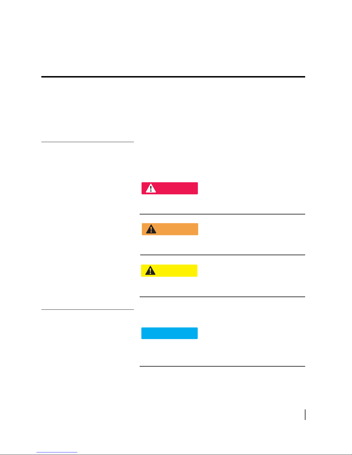
the signal words DANGER, WARNING, CAUTION, or
NOTICE, as illustrated below. To avoid possible property
damage, personal injury, or in some cases death, read and comply
with all safety alert messages.
Messages concerning
personal injury
The signal words DANGER, WARNING, and CAUTION
indicate hazards that could result in personal injury or in some
cases death, as explained below. Each of these signal words
indicates the severity of the potential hazard.
DANGER
DANGER indicates a potentially hazardous situ ation which, if not
avoided, will result in death or serious injury.
WARNING
WARNING indicates a potentially hazardous situation which, if
not avoided, could result in death or serious injury.
CAUTION
CAUTION indicates a potentially hazardous situation which, if
not avoided, could result in minor or moderate injury.
Messages concerning
property damage
A NOTICE concerns property damage only.
NOTICE
NOTICE is used for advisory messages concerning possible
property damage, product damage or malfunction, data loss, or
other unwanted results—but not personal injury.
• Understanding safety alert messages
1037750-0001 Revision A
ix
Page 10
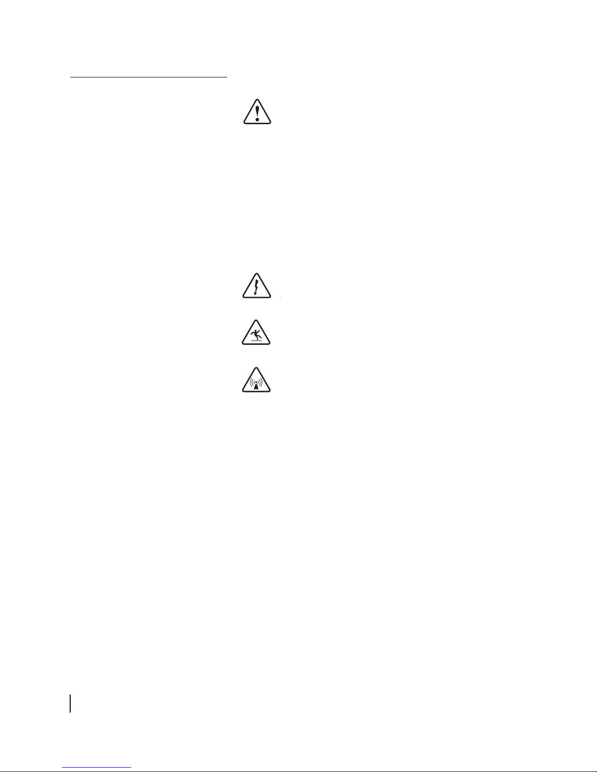
Safety symbols
The generic safety alert symbol
calls attention to a potential personal injury hazard. It appears
xt to the DANGER, WARNING, and CAUTION signal words
ne
as part of the signal word label. Other symbols may appear next
to DANGER, WARNING, or CAUTION to indicate a specific
type of hazard (for example, fire or electric shock). If other
hazard symbols are used in this document they are identified in
this section.
Additional symbols
This document uses the following hazard symbols:
Indicates a safety alert message that concerns a
potential electric shock hazard.
Indicates a safety alert message concerning a
potentially hazardous situation in which you could
fall.
Indicates a safety alert message concerning a
potentially hazardous situation in which you could
be exposed to radio frequency energy.
• Understanding safety alert messages
x
1037750-0001 Revision A
Page 11
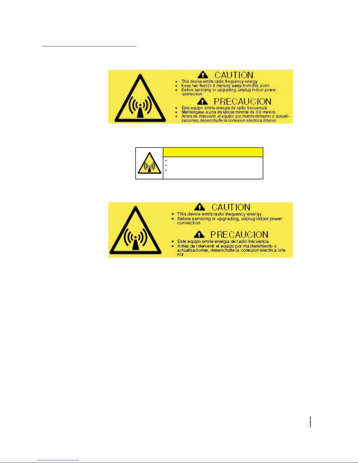
Product warning labels
The following safety alert labels are affixed to the antenna feed
support arm, radio transmitter, and antenna reflector, respectively.
Feed support arm
CAUTION
This device emits radio frequency energy
Keep two feet (0.6 meters) away from this point
Before servicing or upgrading, unplug indoor
power connection
Transmitter
Reflector (back side)
Safety alert labels on the antenna assembly
These labels advise that the antenna emits radio frequency (RF)
y. Because of this potential safety hazard, observe all
energ
cautions on these labels and in the next section, Antenna
installation safety.
• Understanding safety alert messages
1037750-0001 Revision A
xi
Page 12
Antenna installation
safety
Observe the following precautions when installing the satellite
antenna. This manual also includes other safety alerts where
appropriate concerning specific installation procedures.
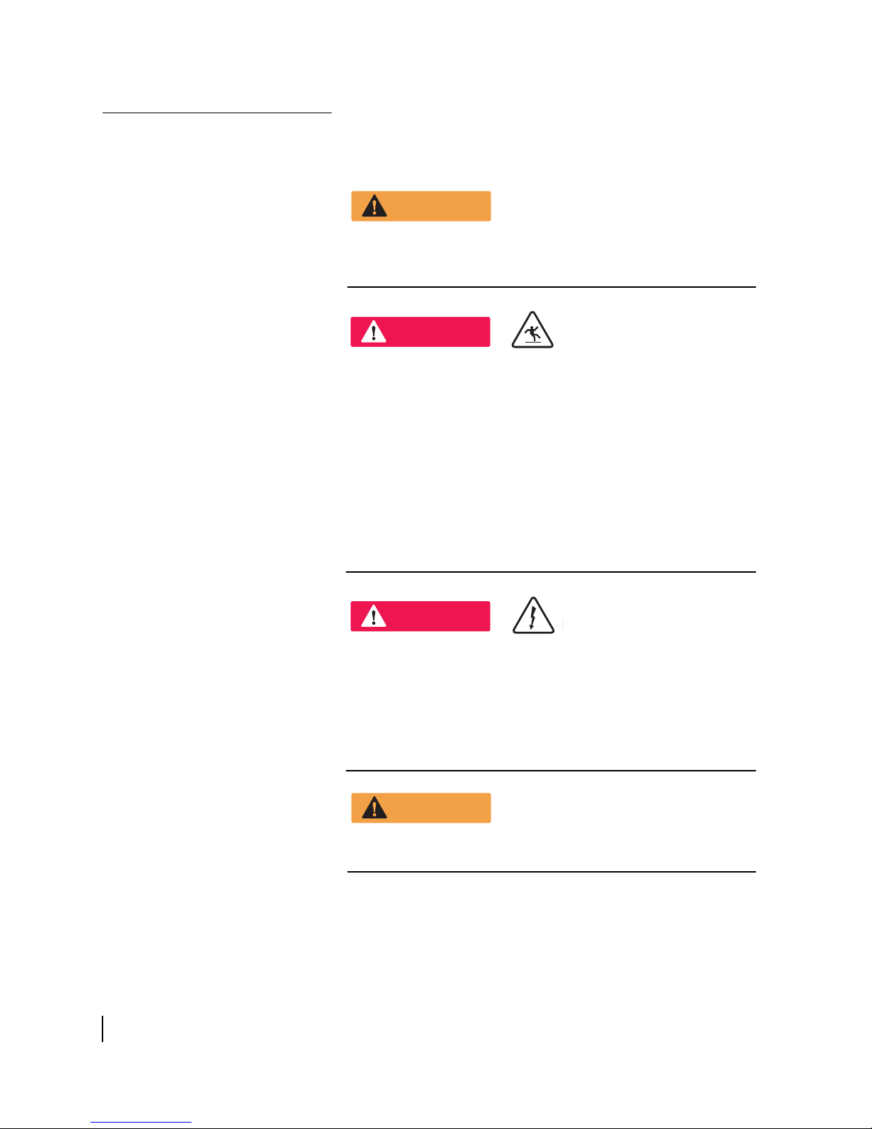
WARNING
Only Hughes-certified installers may install or service Hughes
antennas and their components. Installers must expressly
acknowledge the Hughes requirem ents for Hughes installations.
DANGER
If you work on a roof, tower, or other high structure or use a
ladder or scaffold to access the work site, follow these
precautions to prevent personal injury or death:
• Walk only on sound roof structures.
• Make sure the antenna assembly and installation surface
e structurally sound so that they can support all loads
ar
(equipment weight, ice, and wind).
safety equipment (f or e xample , a lif eline) approp riate for
• Use
th
e work location.
• Follow all manufacturer saf ety precautions for all safety and
her equipment used.
ot
• Perform as many procedures as possible on the ground.
xii
Properly ground the antenna assembly in accordance with all
local and national electrical codes.
• Understanding safety alert messages
1037750-0001 Revision A
DANGER
• To avoid electric shock, stay at least 20 ft from power lines.
• If any part of the antenna or moun t as sem bly comes in
ntact with a power line, call the local power company to
co
remove it. Do not try to remove it yourself.
or pole mount installations, be sure to obtain information
• F
regarding underg
before digging.
round utilities in the proposed location
WARNING
Page 13
WARNING
• Do not work in high wind or rain; or if a storm, lightning, or
other adverse weather conditions are either present or
approaching.
• Do not attempt to assemble , mo v e, or mount the antenn a on
a windy day. Even a slight wind can unexpectedly create
sudden strong forces on the antenna surface.
CAUTION
If the antenna or mount assembly begins to fall during the
installation, do not attempt to catch it. Move away and let it fall.
WARNING
Antennas that have been improperly installed or attached to an
unstable structure are susceptible to wind damage, which can
be very serious or even life threatening. The product owner and
installer assume full responsibility that the installation is
structurally sound to support all loads (weight, wind, and ice)
and is properly sealed against leaks.
• Understanding safety alert messages
1037750-0001 Revision A
xiii
Page 14

CAUTION
Observe these precautions to avoid exposure to RF radiation, a
potential safety ha zard:
• The antenna must be installed in a location not readily
accessib
exposure to potentially harmful levels of radiation.
• Ant
St
must be installed such that the lower lip of t he antenna
reflector is at least 5 ft above any surface upon which a
person might be expected to stand, and 3 ft 3 inches from
an
adjacent structure.
• Ant
w
ith a less than 30° elevation must be installed such that the
lower lip of the antenna reflector is at least 5 ft 9 inches
ab
to stand, and 3 ft 3 inches from an y open ing (such as a doo r
or window) in a building or adjacent structure.
• The
co
ft 7 inches of the edges of a cylindrical space projecting
outward from the antenna reflector toward the satellite.
the above distance requirements cannot be met, the
• If
ant
to the general public, such as a fenced enclosure or a roof.
• A
f
enced area must be large enough to prot ect the general
public from exposure to potentially harmful levels of
radiation.
• Ac
institutional environment must be li mited by a door or a
permanently fastened ladder that is loc ked to den y access to
the general public.
• On
dist
le to children and in a manner that prevents human
ennas mounted in Puerto Rico, the continental United
ates, or at any site with a greater than 30° elevation angle
y
opening (such as a door or window) in a building or
ennas mounted in Canada, Alaska, Hawaii, or any site
ove any surface upon which a person might be expected
antenna must be mounted such that no object that
uld reasonably be e xpected to support a person is within 6
enna must be mounted in a controlled area inaccessible
fenced installation must have a locked entry, and the
cess to a roof installation in a commercial,
ce the transmitter becomes operational, maintain a safe
ance; at least 3 feet.
industrial, or
xiv
• Understanding safety alert messages
1037750-0001 Revision A
Failure to observe these cautions could
other personal injury.
result in injur
y to eyes or
Page 15
CAUTION
Observe these precautions to avoid exposure to RF radiation, a
potential safety ha zard:
• All antennas of any type or size must carry an industry
andard and government approved Radiation Hazard
st
Caution label on the feed support arm.
fenced or roof installation in a commercial, industrial, or
• A
inst
itutional environment must carry a Radiation Hazard
Caution sign on the access door, gate, or permanently
mounted access ladder within plain sight of anyone
approaching the antenna from the front or sides of the
reflector.
Failure to observe these cautions could
other personal injury.
Note: Some installations may require additional precautions. See
the HughesNet System Antenna Site Preparation and Mount
Installation Guide (1035678-0001) for more information.
result in injur
y to eyes or
• Understanding safety alert messages
1037750-0001 Revision A
xv
Page 16

xvi
• Understanding safety alert messages
1037750-0001 Revision A
Page 17

Chapter 1
Overview
This Installation Guide explains how to assemble and install the
Hughes AN8-098P .98m Ka-band antenna. It is written for
qualified installers who are familiar with satellite antenna
installation practices, and are capable of properly applying the
information presented herein.
v
This chapter presents an o
summary of the steps used to assemble and install the antenna,
and supplemental information on tasks related to antenna
installation. These topics are included in the following sections:
erview of the AN8-098P antenna, a
The model AN8-098P
antenna
• The model AN8-098P antenna on
• Antenna installation summary on
• Tasks related to antenna installation on
The Hughes model AN8-098P antenna is designed for Ka-band
applications. Each HughesNet antenna station consists of an
antenna assembly and an indoor unit (IDU), which can be either a
satellite modem or a satellite router. The IDU communicates with
both the HughesNet satellite and the Network Operations Control
Center (NOCC) via the antenna and radio assembly.
The antenna is connected to the ID
(IFL) consisting of two cables: a transmit cable and a receive
cable.
page 1
page 2
page 4
U by an intra-facility link
Chapter 1 • Overview
1037750-0001 Revision A
1
Page 18
Antenna installation
summary
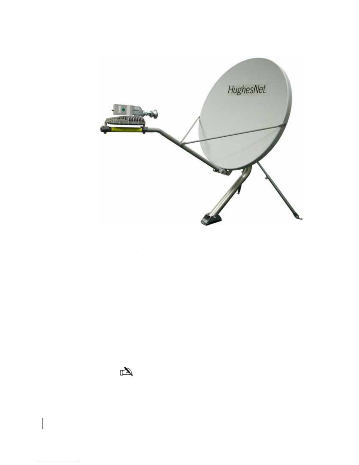
Figure 1: The Hughes model AN8-098P .98 m satellite antenna
This section lists the basic steps and related tasks used to
assemble and install the antenna. These procedures are listed in
the order in which they are to be performed. For more detailed
information on each task, refer to the chapters and documents
listed.
1. Explain the installation pr
ocess to the customer.
2. Conduct a site survey with the customer to identify a suitable
location for the antenna. Se
e the HughesNet Antenna Site
Preparation and Mount Installation Guide (1035678-0001)
for details.
3. Install and apply power to the IDU, following the
in the installation guide for the specific IDU you are
installing.
Note: You must install the IDU before installing the
antenna, to determine the proper pointing values (azimuth and
elevation).
instructions
Chapter 1 • Overview
2
1037750-0001 Revision A
Page 19

4. Connect your laptop computer to the IDU and enter the
installation parameters from the installation reference sheet.
See the HughesNet Ka-Band Antenna Pointing Guide
(1037663-0001) for detailed instructions.
5. Determine the most suitable method for mounting the
antenna, and install the antenna
mount and mast. See the
HughesNet Antenna Site Preparation and Mount
Installation Guide for details.
Note: It is critical that the antenna mast is plumb. It is
impossible to adjust the antenna to correct for a mast that is
not plumb.
6. Attach the reflector bracket to the Az/El mount. See
Chapter 3 – Installing the antenna and r
7. Attach the adapter block to the reflector bracke
Chapter 3 – Installing the antenna and r
adio assembly.
t. See
adio assembly.
8. Attach the antenna reflector. See Chapter 3 – Installing the
tenna and radio assembly.
an
9. Install the feed support arm and support rods. See Chapter 3 –
Installing the antenna and ra
10. Install the radio assembly. See Chapter 3 – Installing th
dio assembly.
e
antenna and radio assembly.
11. Install the feed horn. See Chapter 3 – Installing the antenna
a
nd radio assembly.
12. Attach the Az/El mount and antenna as
mast pipe. See Chapter 3 – Installing the antenna and r
sembly to the antenna
adio
assembly.
13. Install the IFL transmit and recei
ve cables between the IDU
and the antenna. See
Chapter 4 – Cabling and connections.
14
. Ground the antenna assembly. See Tasks related to antenna
installation on pag
15. Determine the proper azimuth and ele
Installing the antenna and ra
e 4.
vation. See Chapter 3 –
dio assembly.
16. Point the antenna in accordance with the instructions in the
HughesNe
t Ka-Band Antenna Pointing Guide
(1037663-0001).
17. Commission the IDU. For instructions, see the inst
allation
guide for the specific IDU you are installing.
Chapter 1 • Overview
1037750-0001 Revision A
3
Page 20

T asks related to antenna
installation
This section discusses tasks related to antenna installation and
explains where to find additional information.
Selecting the
installation site
Installing the
antenna mount
Before selecting an installation site, check the installation
reference sheet to see if a customer-specific site has been
pre-determined and specifie d. Also, refer to the HughesNet
Antenna Site Preparation and Mount Installation Guide
(1035678-0001), which discusses the factors that you should
consider when selecting an antenna installation site.
The first and most important consideration when c
prospective antenna site is whether the area can provide an
acceptable line of sight (LOS) to the satellite. A site with a clear,
unobstructed view of the southern sky is necessary. Also,
consider obstructions that may occur in the future, such as the
growth of trees. Select your antenna site before performing the
installation, so that the antenna will be able to receive the
strongest signal available.
As with any type of construction, a local b
required before installing the antenna. It is the property owner's
responsibility to obtain all permits. If necessary, modify the
installation instructions in this manual in accordance with local
building codes.
Before installing the antenna itself, you must first install a
suitable antenna mount. If the system requires a pole mount
installation, be sure to obtain information about the underground
utilities in the proposed location. Have the appropriate utility
company mark the location of any underground telephone wires,
storm drains, etc. Also, because soils vary widely in composition
and load capacity, it may be necessary to consult a local
professional engineer to determine the appropriate foundation
design.
uilding permit may be
hoosing a
Chapter 1 • Overview
4
1037750-0001 Revision A
For pole mounts that require a concrete base, you must allow at
least 24 hr for the
Be sure to plan and schedule the installation accordingly.
For complete information regarding antenna mount installation,
including
documents in the order listed:
• The customer-specific installation reference sheet
• The Hughes Ne t Antenna Site Preparation
various mounting methods, refer to the following two
Installation Guide (1035678-0001).
concrete to cure before installing the antenna.
and Mount
Page 21

Refer to the installation reference sheet for any customer -specific
guidelines concerning the mount installation. Use only the mount
installation method described in the reference sheet.
If the installation reference sheet does not specify a method, use
only the mount instal
HughesNet Antenna Site Preparation and Mount Installation
Guide (1025678-0001). Most installations in a commercial,
industrial, or institutional environment use a non-penetrating roof
mount.
lation methods documented in the
Installing the IDU
Grounding
Cabling Information
See the installation guide for the specific IDU you are installing.
The entire antenna assembly must be grounded. For grounding
information, refer to your training, best grounding practices, the
Hughes Field Service Bulletin (FSB) HNS Broadband
Requirements for RG-6 and RG-11 IFL Cable Connectors,
Ground Blocks and Ground Block Location (FSB 050518_01),
and applicable parts of the National Electrical Code (NEC).
For a list of approved cable types for the IFL between the antenna
and the IDU, see the Hughes FSB, IFL Cable, Approved List
(with lengths) for SPACEWAY Domestic Installations (FSB
080202_01). The FSB lists the maximum cable length for each
approved cable type for all relevant radios types.
Because it is impossible to predict the requirements specif
each installation site, you must use your own judgement and best
practices to determine how to route the IFL transmit and receive
cables.
ic to
Chapter 1 • Overview
1037750-0001 Revision A
5
Page 22

Chapter 1 • Overview
6
1037750-0001 Revision A
Page 23

Antenna kit
components
Chapter 2
Antenna parts and required tools
This chapter describes the components and parts provided with
the AN8-098P Ka-band antenna kit. It also lists the hardware and
tools needed to properly assemble and install the antenna. This
chapter contains the following sections:
• Antenna kit components on page 7
• Small hardware parts list on pag
• Tools on page 15
CAUTION
Metal components may contain sharp edges. Use care when
un-packing and handling antenna parts.
e 14
Upon receiving the kit, unpack and inspect the antenna
components and hardware to make sure all parts have been
received in good condition. If any parts appear to have been
damaged in transit, immediately contact the freight carrier. If any
parts appear to be missing or damaged, but not as a result of
handling in transit, contact your dealer or distributor.
c
The antenna kit is shipped in three
the contents of each container.
Note: To avoid potential damage, leave all components in their
protective packages until required.
ontainers. Figure 2 identifies
Chapter 2 • Antenna parts and required tools
1037750-0001 Revision A
7
Page 24

Chapter 2 • Antenna parts and required tools
8
1037750-0001 Revision A
Figure 2: Antenna kit components
Note: The radio assembly is shipped separately and may not
arrive at the same time as the other two cartons.
The main components of the antenna kit are:
• Azimuth/Elev
ation (Az/El) mount assembly
• Reflector bracket and adapter block
• Antenna reflector
• Feed support arm and support rods
• Radio assembly
• Feed horn and
c
ollar
Related components (not shown):
• Tri-mast or other mount
Page 25

The following sections describe each component of the antenna
kit.
Az/El mount assembly
The Az/El mount sho wn in Figure 4 consists of the Az/El cani ster ,
the elevation scale, and the azimuth and elevation adjustment
tools.
The Az/El canister supports the ante
nna and secures it to the
mast. The elevation scale is used to measure the angle of antenna
elevation. The fine azimuth and elevation tools are used to finely
adjust the azimuth and elevation of the reflector during antenna
pointing. See the HughesNet Ka-Band Antenna Pointing Guide
(1037663-0001) for detailed instructions.
Figure 3: Az/El mount assembly
Chapter 2 • Antenna parts and required tools
1037750-0001 Revision A
9
Page 26

Reflector bracket
and adapter block
The reflector bracket supports the antenna reflector. It attaches to
the Az/El mount assembly. The adapter block attaches to the
reflector bracket and anchors the feed support arm to the antenna
assembly. Figure 4 shows the reflector bracket and adapter block.
Figure 4: Reflector bracket and adapter block
Antenna reflector
The antenna reflector shown in Figure 5 focuses the transmitted
and received RF signals. It attaches to the reflector bra
cket and
the adapter block.
10
Chapter 2 • Antenna parts and required tools
1037750-0001 Revision A
Figure 5: Antenna reflector
Page 27

NOTICE
To avoid damage to the antenna reflector, handle it with care.
Feed support arm
and support rods
Figure 6: Feed support arm and support rods
Radio assembly
The antenna kit contains one feed support arm and two support
rods, shown in Figure 6. The feed support arm supports the radio
assembly and feed horn. The support rods
attach to the reflector
to stabilize the arm and provide additional support.
The radio assembly shown in Figure 7 consists of the radio
transmitter, low noise block converter (LNB), transmit/receive
isolation assembly (TRIA), and polarizer
waveguide.
Figure 7: Radio assembly
Chapter 2 • Antenna parts and required tools
1037750-0001 Revision A
11
Page 28

Feed horn and collar
The feed horn, shown in Figure 8, attaches to the polarizer
waveguide on the radio assembly by w ay of the two-piece collar.
ed horn gathers the reflected signal from the antenna
The fe
reflector and channels it toward the LNB.
Figure 8: Feed horn and co llar
NOTICE
• Do not remove the protective packing material from
the feed horn window until installation of the radio assembly
is complete
• Do not attempt to remove the feed horn window at
y time.
an
• Be careful not to damage the feed horn window.
not touch the plastic film.
Do
.
12
Related Components
Tri-mast (or other
antenna mount)
Chapter 2 • Antenna parts and required tools
1037750-0001 Revision A
Although the tri-mast is not part of the antenna kit, it is described
here because it is the most commonly used mounting option for
the AN8-098P Ka-band antenna. As shown in Figure 9, the
tri-mast can be positioned in a number of configurat
it for mounting onto surfaces of v arious an gles. Fo r other suitable
antenna mounting options, see the HughesNet Antenna Site
Preparation and Mount Installation Guide (1035678-0001).
ions to adapt
Page 29

Wall
Mast
Struts (2)
T0144002
Flat roof
Figure 9: Tri-mast in various configurations
Pitched roof
Chapter 2 • Antenna parts and required tools
1037750-0001 Revision A
13
Page 30

Small hardware
parts list
Table 1 lists the small hardware parts included in the antenna kit.
Ta ble 1: Small hardware parts
Part Quantity
5/16 × ¾-inch carriage bolt
½-inch hex head serrated flange
nut
½ × 1-inch hex head bolts
½-inch flat washers
½ × 1-3/8-inch thread-cutting
bolts
7/16 × 2.5-inch hex head bolt 1 Feed support arm to adapter
7/16-inch flat washer 1
7/16-inch lock washer 1
7/16 × 1-inch hex head bolts 2 Support rods to reflector Figure 16 on page 24
7/16-inch lock washers 2
7/16-inch serrated flange hex nuts 2
7/16 × 2-inch hex head bolt 1 Support rods to feed support
7/16-inch flat washer 1
7/16-inch lock washer 1
7/16-inch serrated flange hex nut 1
½ × 2-inch hex head bolts
½-inch flat washers
0.9-inch inside diameter O-ring 1 Feed horn and collar to radio
#6-32 hexagonal socket head
en) screw
(All
4 Reflector bracket to Az/El
4
4 Adapter block to reflector
4
4 Antenna reflector to reflector
2 Radio assembly (transmitter)
2
2
Listed parts are
used to attach...
mount assemb
cket
bra
cket
bra
block
arm
and adapter brackets (2) to
feed support arm
assembly
ly
Illustration showing
where parts are used
Figure 10 on page 19
Figure 12 on page 20
Figure 14 on page 22
Figure 15 on page 23
Figure 17 on page 24
Figures 18 on pages 25
Figure 24 on page 30
14
1037750-0001 Revision A
Chapter 2 • Antenna parts and required tools
Page 31

Tools
Table 2 lists the tools required to assemble and install the
antenna.
Table 2: Tools required to assemble and install the antenna
Tool Details
5/16-inch bolts.
Socket wrench, ½-inch
(with 3-inch extension)
Open-end wrench,
½-inch
2 open-end or socket
s
7/16-inch
wrenche
Torque wrench With
Long-shaft hexagonal
ball d
Torque wrench for
hexagon
Bubble level Used to make sure that the mast is plumb.
Compass Used in determining antenna azimuth.
Pencil Carpenter’s pencil.
Dielectric grease Used to prevent moisture contamination
Weatherproofing tape Used to keep moisture away from cable
Approved RG6 cable Used for IFL between IDU and antenna.
UV-rated cable ties Used to secure slack in cables to antenna
,
river (7/64-inch)
al socket
For
For 5/16-inch bolts. Two of the Az/El
canister nuts are not accessible by socket
wrench. Some nuts and bolts require a
second wrench to prevent turning.
For
1/4-inch bolts. Some nuts and bolts
require a second wrench to prevent turning.
½-inch and 7/16-inch sockets capable
of torquing to 8 ft-lb.
For #6-32 Allen screws. Driver shaft should
be at least 5 inches long.
Must fit a 3-mm hexagonal socket and be
capable of torquing to 15 in-lb.
i
from occurr
connections.
connectio
ast.
m
ng on coaxial cable
ns
Chapter 2 • Antenna parts and required tools
1037750-0001 Revision A
15
Page 32

16
Chapter 2 • Antenna parts and required tools
1037750-0001 Revision A
Page 33

Chapter 3
Installing the antenna and
radio assembly
This chapter explains how to assemble and install the antenna,
radio assembly, and associated hardware. Topics in this chapter
include:
Determining the
pointing values
• Determining the pointing values on pa
• General instructions for assembling
• Installing the reflector bracket on pag
• Installing the antenna reflector on pag
• Installing the feed support arm and support r
• Installing the radio assembly on page 25
• Installing the
• Installing the antenna assembly onto the mast pipe
page 31
feed horn on pa
ge 28
ge 17
the antenna on page 18
e 19
e 21
ods on page 23
on
CAUTION
Before you inst all the antenna, read all safety information in
Understanding safety alert messages on page ix.
Before installing the antenna, you must install and power up the
IDU. Refer to the appropriate IDU installation guide for
instructions.
Once the IDU is powered up, connect it to your laptop using an
Ethernet cable, then use your global positioning system
recei
ver to calculate the exact latitude and longitude of the
antenna site. Following the instructions in the HughesNet
Ka-Band Antenna Pointing Guide (1037663-0001) to enter the
latitude and longitude information into the IDU to determine the
initial antenna azimuth and elevation values. Record these values
and keep them handy for reference as you install and point the
antenna.
(GPS)
Chapter 3 • Installing the antenna and radio assembly
1037750-0001 Revision A
17
Page 34

General instructions for
assembling the antenna
Before you assemble the antenna, read these important
instructions:
• Mast – The an
tenna mast must be installed before you can
install the antenna. For information on installing the mast,
see the HughesNet Antenna Site Preparation and Mount
Installation Guide (1035678-0001).
Note: The mast diameter must be 2.5-inch nominal pipe size
(2.88-inch outside diameter).
• Sequence of steps – When you assemble the antenna, be sur
to follow the instructions in this chapter in the order they are
presented.
WARNING
For rooftop installations, assemble the antenna on the ground
and then carry the fully assembled antenna up to the roof.
• Tightening hardware – Do
hardware until you are instructed to do so. (See also the next
item, Torque.)
• Torque – To ensure successful installat
critical that you tighten all nuts and socket-head screws to the
maximum torque values shown in Table 3.
Ta ble 3: Torque specifications
Fastener Maximum torque
5/16-inch bolts 8 ft-lb.
¼-inch bolts 5 ft-lb.
M4 hexagonal
socket head screws
not tighten any nuts or other
ion of the antenna, it is
15 in-lb.
e
18
Chapter 3 • Installing the antenna and radio assembly
1037750-0001 Revision A
Page 35

Installing the
reflector bracket
Begin the antenna assembly by attaching the reflector bracket to
the Az/El mount assembly:
1. Loosen the two screws on either side of the Az/El mount
elev
ation linkage.
2. Clip the hooks near the top of the reflector bracket over the
elev
ation linkage as shown in Figure 10.
Figure 10: Attaching the reflector bracket to the Az/El mount
3. Align the tabs on the reflector bracket with the two pivot
holes in the sides of
and insert two carriage bolts from the inside, out through the
les.
ho
4. Secure the reflector bracket to the Az/El mount from the
outside with two ½-inch nuts.
Note: Ensure that the carriage bolts are firmly seated before
tightening the nuts.
Chapter 3 • Installing the antenna and radio assembly
the Az/El mount as shown in Figure 11,
1037750-0001 Revision A
19
Page 36

Figure 11: Securing the reflector bracket
5. Fit the adapter block between the extensions on either side of
the reflector bracket arm in the position shown in Figure 12.
20
Chapter 3 • Installing the antenna and radio assembly
1037750-0001 Revision A
Figure 12: Attaching the adapter block to the reflector bracket
Page 37

6. Secure the adapter block in place by inserting four ½ ×
1-inch hex head bolts, with washers, through the holes in the
reflector bracket arm, and into the threaded sockets on the
adapter block (two on each side). Do not tighten the bolts at
this time.
Installing the antenna
reflector
To attach the antenna reflector to the reflector bracket:
1. Place the reflector in position on the reflector brack
the two keys on the bottom of the reflector fit into the
corresponding notches on the adapter block as shown in
Figure 13.
Figure 13: Aligning the reflector with the adapter block
et so that
Chapter 3 • Installing the antenna and radio assembly
1037750-0001 Revision A
21
Page 38

2. Align the mounting holes in the reflector with the holes in the
reflector bracket as shown in Figure 14.
Figure 14: Attaching the antenna reflector
3. Insert four thread-cutting bolts (½-inch × 3/
4-inch) into the
holes in the reflector bracket from the back, and through the
corresponding holes in rear of the reflector.
4. Once the reflector is in place, tighten the nuts lightl
y, only
until snug, then tighten the four bolts that secure the adapter
block to the reflector bracket.
22
Chapter 3 • Installing the antenna and radio assembly
1037750-0001 Revision A
Page 39

Installing the
feed support arm
and support rods
To attach the feed support arm and support rods:
1. Position the feed support arm undern
shown in Figure 15.
2. Insert a single 7/16-inch × 1
and flat washer, up through the feed support arm from below
and into the threaded socket of the adapter block.
Note: There are two holes near the end of the feed support
arm. Be sure to insert the bolt through the hole that is furthest
from the end, as shown in
3. Tighten until secure.
¾-inch bolt with lock washer
Figure 15.
eath the adapter block as
Figure 15: Attaching the feed support arm to the adapter block
4. Attach the two support rods to
sides, u
shown in Figure 16. As shown in the figure, the two tips at
the opposite ends of the support rods are not the same. Be
sure to attach the longer-tipped
illustrated in Figure 16. Do not tighten.
sing one 7/16 x 1-inch hex head bolt for each rod, as
Chapter 3 • Installing the antenna and radio assembly
the reflector rim on opposite
ends to the reflector, as
1037750-0001 Revision A
23
Page 40

Figure 16: Attaching the support rods to the reflector (right rod shown)
5. Attach the free ends of the support rods to the feed support
arm as shown in Figure 17, using a single 7/16 x 1.25-inch
bolt, lock washer, and flat washer.
Figure 17: Attaching the support rods to the feed support arm
6. Secure the bolt with a 7/16-inch nut and tighten.
7. Tighten the two bolts securing the rods to the reflector
.
24
Chapter 3 • Installing the antenna and radio assembly
1037750-0001 Revision A
Page 41

Installing the radio
assembly
To mount the radio assembly to the feed support arm:
1. Place the two adapter brackets on the feed support arm as
show
n in Figure 18.
Figure 18: Attaching the radio assembly
Adjusting
circular polarization
2. As shown in the fi gure, position the radio a
adapter brackets so that the waveguide end of the radio is
nearest to the reflector.
3. Lower the radio onto the adapter brackets and insert one
½-inch × 1.75-
washer up through the feed support arm and adapter bracket,
into each of the two the threaded sockets in the radio
transmitter.
4. Tighten both bolts to secure the radio to
It may be necessary for you to reposition the polarizer waveguide
on the radio assembly to set the proper polarization between the
radio transmitter and the antenna reflector. Before proceeding,
check the installation reference sheet to determine whether the
installation calls for left-hand circular polarization (LHCP) or
right-hand circular polarization (RHCP).
Once you determine which polarization setting is
the
position of the polarizer waveguide on the radio to determine
whether an adjustment is necessary. From the rear of the radio,
looking toward the reflector, you can easily determine whether
the polarizer is currently set for LHCP or RHCP by the way it
leans. (See Figure 19.)
inch bolt, with 5/16-inch flat washer and lock
ssembly abo
the feed support arm.
required, check
ve the
Note: There is no default factory setting for transmit
polarization. Radios can be shipped with either setting.
Chapter 3 • Installing the antenna and radio assembly
1037750-0001 Revision A
25
Page 42

Figure 19: Determining the polarization setting
To reposition the polarizer:
1. Remove the two-piece polarizer collar by loosening and
removing the
two Allen screws that hold it together.
2. Separate the polarizer from the TR
turn (clockwise for LHCP or counter-clockwise for RHCP),
until the appropriate notch lines up with the key on the end of
the TRIA. As shown in Figure 20, the LHCP notch is
adjacent to the L on the polarizer and
adjacent to the R on the polarizer).
IA and rotate it one quarter
the RHCP notch is
26
Chapter 3 • Installing the antenna and radio assembly
1037750-0001 Revision A
Page 43

Figure 20: Adjusting cir cula r pola rization (collar removed)
3. After making the adjustment, reseat the w
aveguide with the
TRIA and reassemble the collar as follows:
Fit the two halves of the collar around the waveguide as
show
n in Figure 21 so that the notches in the collar come
together around the ridge formed at
the waveguide seam.
When properly aligned, the seam formed by the tw o halves of
the collar will line up with the seam on the waveguide.
4. Reinsert the two Allen screws into the collar
and tighten
secure the polarizer in place. Be sure to tighten the collar
completely.
NOTICE
You must assemble the collar exactly as described abo v e and as
shown in Figure 21. Failure to do so could allow moisture to
accumulate inside the TRIA, causing damage to the radio.
to
Chapter 3 • Installing the antenna and radio assembly
1037750-0001 Revision A
27
Page 44

Figure 21: Securing the waveguide collar
Installing the feed horn
NOTICE
• Do not remove the protective packing material from
the feed horn window until installation of the radio assembly
is complete
• Do not attempt to remove the feed horn window at
y time.
an
• Be careful not to damage the feed horn window.
not touch the plastic film that covers the window.
Do
To attach the feed horn to the radio assembly:
1. Remove and discard the protecti ve seal from the polarizer on
the radio assembly (sho
.
wn in Figure 22).
28
Chapter 3 • Installing the antenna and radio assembly
1037750-0001 Revision A
Page 45

Figure 22: Remove the protective seal from the polarizer
2. Remove the dust cap from the stem of the feed horn and
insert the O-ring into the groove inside the stem as shown in
Figure 23.
Figure 23: Insert O-ring into groove at mouth of feed horn
Chapter 3 • Installing the antenna and radio assembly
1037750-0001 Revision A
29
Page 46

3. Position the feed horn against the waveguide as shown in
Figure 24.
Figure 24: Feed horn position
4. Fit the two halves of the feed horn collar around the ridge at
h
the point where t
in Figure 25. When properly aligned, the seam forme
e feed horn meets the wave guide, as shown
d by the
two halves of the collar will line up with the seam on the
w
aveguide as shown in the figure.
30
Chapter 3 • Installing the antenna and radio assembly
1037750-0001 Revision A
Figure 25: Attaching the feed horn collar
Page 47

NOTICE
You must assemble the collar exactly as described abo v e and as
shown in Figure 25 before fully assembling the collar. Failure to
do so will result in damage to the polariz
5. Insert two Allen screws into the collar and tighten to secure
the feed horn in place.
6. At this point, fully tighten any hardware that is not
tight—however, leave nuts that are used for pointing
adjustments slightly loose or just snug.
er waveguide.
Installing the antenna
assembly onto
the mast pipe
Bubble must be centered
between marks.
Follow these steps to mount the antenna assembly onto the mast:
1. Before you install the antenna assembly onto the mast pipe,
use a b
ubble level to make sure that the mast is plumb.
Check the mast at two perpendicular locations, as shown in
Figure 26.
Note: It is critical that the antenna mast is plumb. It is
impossible to adjust the antenna to correct for a mast that is
not plumb.
To make sure the mast is
plumb, check with the level
in two positions at right
angles to each other.
Mast
Level
Bubble
level
Mast
2nd level
position
Top view
Side view
Figure 26: Making sure the mast is plumb
Chapter 3 • Installing the antenna and radio assembly
1037750-0001 Revision A
T0144012
31
Page 48

2. Slide the Az/El canister down onto the mast as shown in
Figure 27.
3. Tighten.
Note: The mast diameter must be 2.5-inch nominal pipe size
(2.88-inch outside diameter).
32
Chapter 3 • Installing the antenna and radio assembly
1037750-0001 Revision A
Figure 27: Installing the antenna onto the mast pipe
Page 49

This completes the assembly phase of the antenna installation
process. Depending on its orientation, the antenna should look
similar to the one shown in Figure 28.
Figure 28: Assembled antenna
To proceed with the installation, you must route the IFL transm
and receive cables between the antenna and the IDU. See
Chapter 4 – Cabling and connections.
Chapter 3 • Installing the antenna and radio assembly
1037750-0001 Revision A
it
33
Page 50

34
Chapter 3 • Installing the antenna and radio assembly
1037750-0001 Revision A
Page 51

Chapter 4
Cabling and connections
This chapter illustrates where the antenna transmit, receive, and
ground connectors are located; demonstrates how to route the
transmit and receive cables at the antenna; and explains how to
connect the transmit and receive cables to the radio assembly.
You must connect all of these cables before you can point the
antenna toward the HughesNet system satellite.
Topics in this chapter include:
• Cabling requirements on page 35
• Routing the cables at the antenna on
• Connecting the transmit and receive cables on pa
• Ground connection on page 41
page 36
ge 38
Cabling requirements
For a list of approved coaxial cable types for the IFL between the
antenna and the IDU, see the Hughes FSB, IFL Cable, Approved
List (with lengths) for SPACEW AY Domestic Installations, (FSB
080202-01). The FSB lists the maximum cable length for each
approved cable type, for all applicable radio types.
Because it is impossible to predict the requirements specif
each installation site, you must use your own judgement and best
practices to determine how to route the IFL cables.
ic to
NOTICE
Coaxial cables and connectors can corrode if exposed to
moisture. Use only compression type connectors, and
weatherproof them with dielectric grease and weatherproofing
tape.
Note: For connector requirements, see the Hughes FSB,
HN Broadband Requirements for RG-6 and RG-11 IFL
Cable Connectors, Ground Blocks and Ground Block
Location (FSB 50518_01).
Chapter 4 • Cabling and connections
1037750-0001 Revision A
35
Page 52

Routing the cables at
the antenna
Route the coaxial transmit (Tx) and receive (Rx) cables at the
antenna as follows:
1. Route the Tx cable (marked with blue electrical tape) over the
Az/El mount assembly, do
wn behind the reflector, and along
the feed support arm to the rear of the transmitter, in a
configuration similar to that shown in Figure 29.
Note: Do not exceed the minimum bending radius specified by
the cable manufacturer.
Figure 29: Transmit and receive cable configurations
36
Chapter 4 • Cabling and connections
1037750-0001 Revision A
2. Leave a 10-foot service loop and secure it to either the mast,
Az/El mount, or reflecto
Note:
1. Do not lea
mounting surface.
2. Do not
adjustment nuts on the Az/El mount assembly.
ve the service loop lying on the roof or other
block access to the azimuth and elevation
r bracket.
Page 53

3. Coil the extra cable, leave a drip loop, and secure the Tx
cable with cable ties.
4. Route the Rx cable (marked with red electrical tape
) over the
Az/El mount assembly, down behind the reflector, and along
the feed support arm to the LNB, in a configuration similar to
that shown in Figure 29 above.
Note: Do not exceed the minimum bending radius specified by
the cable manufacturer.
5. Leave a 10-foot service loop and secure it to either the mast,
Az/El mount assembly, or ref
Note:
1. Do not lea
mounting surface.
2. Do not block
mount assembly.
ve the service loop lying on the roof or other
access to the adjustment nuts on the Az/El
lector bracket.
6. Coil the extra cable, leave a drip loop, and secure the Rx
ble with cable ties.
ca
Chapter 4 • Cabling and connections
1037750-0001 Revision A
37
Page 54

Connecting the transmit
and receive cables
This section explains how to connect the Tx and Rx cables to the
radio assembly at the antenna.
Note: You should protect all outdoor cable connections with
dielectric grease and weatherproofing tape as shown in Figure 30.
However, because the antenna pointing procedure re
you disconnect the cables, you should wait until the pointing
process is complete before weatherproofing the connections.
quires that
Figure 30: Weatherp r oo fin g th e cable connec to rs
38
Chapter 4 • Cabling and connections
1037750-0001 Revision A
Page 55

Transmit cable
Connect the Tx cable to the radio transmitter as follows:
1. Remove power from the IDU.
2. Fill the Tx cable connector (mark
ed with blue electrical tape)
with dielectric grease.
3. Connect the Tx cable to the transmitter connector marked
IFL, sho
wn in Figure 31.
NOTICE
Coaxial cables and connectors can corrode if exposed to
moisture. Use only compression type connectors, and
weatherproof them with dielectric grease and weatherproofing
tape.
4. Tighten the cable connector until it is finger-tight, then
tighten an additional
5. If necessary, secure the cable with cable ties.
1/4 turn with a 7/16-inch wrench.
Figure 31: Transmit connector
Chapter 4 • Cabling and connections
1037750-0001 Revision A
39
Page 56

Receive cable
Connect the Rx cable to the LNB as follows:
1. Ensure that power has been remov
ed from the IDU.
2. Fill the Rx cable connector (marked with blue electrical tape)
with dielectric
3. Connect the Rx cable to the rece
grease.
ive connector on the LNB,
shown in Figure 32.
NOTICE
Coaxial cables and connectors can corrode if exposed to
moisture. Use only compression type connectors, and
weatherproof them with dielectric grease and weatherproofing
tape.
40
Chapter 4 • Cabling and connections
1037750-0001 Revision A
Figure 32: Receive connector
4. Tighten the cable connector until it is finger-tight, then
tighten an additional
1/4 turn with a 7/16-inch wrench.
5. If necessary, secure the cable with cable ties.
6. After both the Tx and Rx cables are connected to the radio
and the IDU, reapply powe
r to the IDU in accordance with
the instructions in the IDU installation guide.
Page 57

Ground connection
Ground the antenna mast at the Az/El mount by attaching the
ground wire to the elevation lockdown bolt as shown in
Figure 33. For specific grounding proc edures, refer to the sources
listed in Grounding on
Note: Although the radio transmitter contains a ground screw, a
separate ground wire to the radio assembly is not required; the
radio assembly is grounded through the metallic shield of the
coaxial cable.
page 5.
Figure 33: Ground screw on the Az/El mount
This completes the installation. Yo
u must now point the antenna.
See the Ka-Band Antenna Pointing Guide (1037663-0001) for
details.
Chapter 4 • Cabling and connections
1037750-0001 Revision A
41
Page 58

42
Chapter 4 • Cabling and connections
1037750-0001 Revision A
Page 59

Adjusting the antenna
azimuth and elevation
This chapter describes the process by which to adjust the antenna
azimuth and elevation to the correct position for optimum
transmission and reception. As the installer, you will perform
these procedures during the antenna pointing process. This
chapter discusses the mechanical adjustments used to modify the
position of the antenna only. It does not discuss the pointing
process itself. For information on pointing the AN8-098P and all
HughesNet Ka-Band antennas, see the HughesNet Ka-Band
Antenna Pointing Guide (1037663-0001).
This chapter contains the follo
• Adjusting the
• Adjusting the azimuth on
elevation on pag
wing sections:
e 44
page 46
• Adjusting the antenna azimuth and elevation
1037750-0001 Revision A
43
Page 60

Adjusting the elevation
To adjust the antenna elevation:
1. Unlock the elevation by loosening the
5/16-inch elevation
lockdown nuts on either side of the Az/El mount. Figure 34
shows the location of the nuts (only one nut is shown).
Figure 34: Elevation adjustment components
2. Loosen the top elevation adjustment
nut and spin it
counter-clockwise until it rides an inch or two up the
elevation adjustment rod.
3. Use the lower nut to adjust the elevation.
4. As shown in Figure 35, the black line on the bar behind the
lockdown nut acts as a pointer to
indicate the value in the
elevation scale. F or example, the antenna shown in the figure
is adjusted to 26°.
44
• Adjusting the antenna azimuth and elevation
1037750-0001 Revision A
Page 61

Figure 35: Elevation marker
5. Spin the top elevation adjustment nut clockwise until it is
snug against the base plate.
6. Lock down the elev ation by tightenin
g the two lockdown nuts
on either side of the Az/El mount using a ½-inch socket and
torque wrench.
• Adjusting the antenna azimuth and elevation
1037750-0001 Revision A
45
Page 62

Adjusting the azimuth
To adjust the antenna azimuth:
1. Ensure that the three 5/16-inch azimuth lockdo
wn nuts at the
bottom of the Az/El canister (shown in Figure 36) are loose
enough that the antenna assembly rotates
freely on the mast.
Figure 36: Azimuth adjustment components
2. Manually point the antenna reflector as accurately as possible
in the appropriate
direction as indicated on the installation
reference sheet.
NOTICE
Do not attempt to adjust the azimuth manually by pulling on the
antenna reflector or feed support arm. Doing so could cause
permanent damage to the antenna.
3. Tighten the three lockdown nuts just enough so th
antenna does not rotate freely.
at the
46
• Adjusting the antenna azimuth and elevation
1037750-0001 Revision A
Page 63

4. Using a ½-inch wrench, rotate the azimuth adjustment bolt
shown in Figure 36 in either direction to achieve the desired
azimuth angle.
Note: Azimuth measurements are calibrated relative to true
north, not magnetic north.
5. Verify the azimuth with a compass
and tighten the three
lockdown nuts fully to secure the antenna in position.
• Adjusting the antenna azimuth and elevation
1037750-0001 Revision A
47
Page 64

48
• Adjusting the antenna azimuth and elevation
1037750-0001 Revision A
Page 65

Acronyms and abbreviations
A
Az – Azimuth
E
El – Elevation
F
FSB – Field service bulletin
ft – Foot
ft-lb – Foot-pound
G
GPS – Global positioning system
H
hr – Hour
I
N
NEC – National Electrical Code
NOCC – Network Operations Control Center
R
RF – Radio frequency
RHCP – Right-hand circular polarization
Rx – Receive
T
TRIA – Transmit/receive isolation assembly
Tx – Transmit
IDU – Indoor unit
IFL – Intra-facility link
in-lb – Inch-pound
L
LHCP – Left-hand circular polarization
LNB – Low noise block converter
LOS – Line of sight
M
m – Meter
• Acronyms and abbreviations
1037750-0001 Revision A
49
Page 66

50
• Acronyms and abbreviations
1037750-0001 Revision A
Page 67

Index
A
Adapter block 10
Adjusting circular polarization 25
Antenna
adapter block
illustrated 33
mount installation 4, 12
reflector 10
tailpiece 10
unpacking 7
Az/El mount assembly 19
az/el mount assembly 9
10
C
Cables
approved types
connecting to radio assembly 38
maximum length 5, 35
receive cable 40
routing at the antenna 36
service loop 36
transmit cable 39
Circular polarization, adjusting 25
Collar
polarizer
Connecting
cables to the radio assembly
receive cable 40
transmit cable 39
Connectors 35
5, 35
26, 28
38
F
G
GPS 17
Grounding 5
ground screw location 41
H
Hardware parts list 14
I
IFL 5
Installation site 4
Installation, summary of steps 2
Installing
antenna mount
pole mount installation requirements 4
feed horn 28–31
feed support arm 23
radio assembly 25–28
reflector 21–22
reflector bracket 19–21
4–5, 12
L
Leveling the mast 31
P
Parts list 14
Pointing values, determining 17
Polarization. See Circular polarization
Polarizer collar
Polarizer waveguide 25
26
Feed horn
description
installing 28–31
Feed support arm
description
installing 23
12
11
R
Radio assembly
description
installing 25–28
Receive cable
connecting to the LNB
routing 37
11
40
• Index
1037750-0001 Revision A
51
Page 68

Reflector
description 10
installing 21–22
Reflector bracket
description
installing 19–21
10
S
Summary of installation steps 2
Support rods 11
T
Tasks related to installation 2
Tool list 15
Torque 18
Transmit cable
connecting
routing 36
Transmitter 11
connecting 39
Tri-mast 12
39
U
Unpacking the antenna 7
W
Waveguide, polarizer 25
52
• Index
1037750-0001 Revision A
 Loading...