

Page 1

HN System
Installation Manual for .98 m Ku-band Upgradeable Antenna Model AN6-098P
1037312-0001
Revision A
March 2, 2007
Page 2

Copyright © 2007 Hughes Network Systems, LLC
All rights reserved. This publication and its contents are proprietary to Hughes Network Systems,
LLC. No part of this publication may be reproduced in any form or by any means without the written
permission of Hughes Network Systems, LLC, 11717 Exploration Lane, Germantown, Maryland
20876.
Hughes Network Systems, LLC has made every effort to ensure the correctness and completeness
of the material in this document. Hughes Network Systems, LLC shall not be liable for errors
contained herein. The information in this document is subject to change without notice. Hughes
Network Systems, LLC makes no warranty of any kind with regard to this material, including, but not
limited to, the implied warranties of merchantability and fitness for a particular purpose.
Trademarks
Hughes, Hughes Network Systems, and HughesNet are trademarks of Hughes Network Systems,
LLC. All other trademarks are the property of their respective owners.
Page 3
Important safety information
For your safety and protection, read this entire installation manual
before you attempt to install the satellite antenna. In particular,
read this safety section carefully. Keep this safety information
where you can refer to it if necessary.
Types of warnings used in this manual
This section introduces the various types of warnings used in this
manual to alert you to possible safety hazards.
DANGER
Indicates an imminently hazardous situation, which, if not
avoided, will result in death or serious injury.
WARNING
Indicates a potentially hazardous situation, which, if not
avoided, could result in death or serious injury.
CAUTION
Indicates a potentially hazardous situation, which, if not
avoided, may result in minor or moderate injury.
CAUTION
Indicates a situation or practice that might result in property
damage.
• Important safety information
1037312-0001 Revision A
iii
Page 4
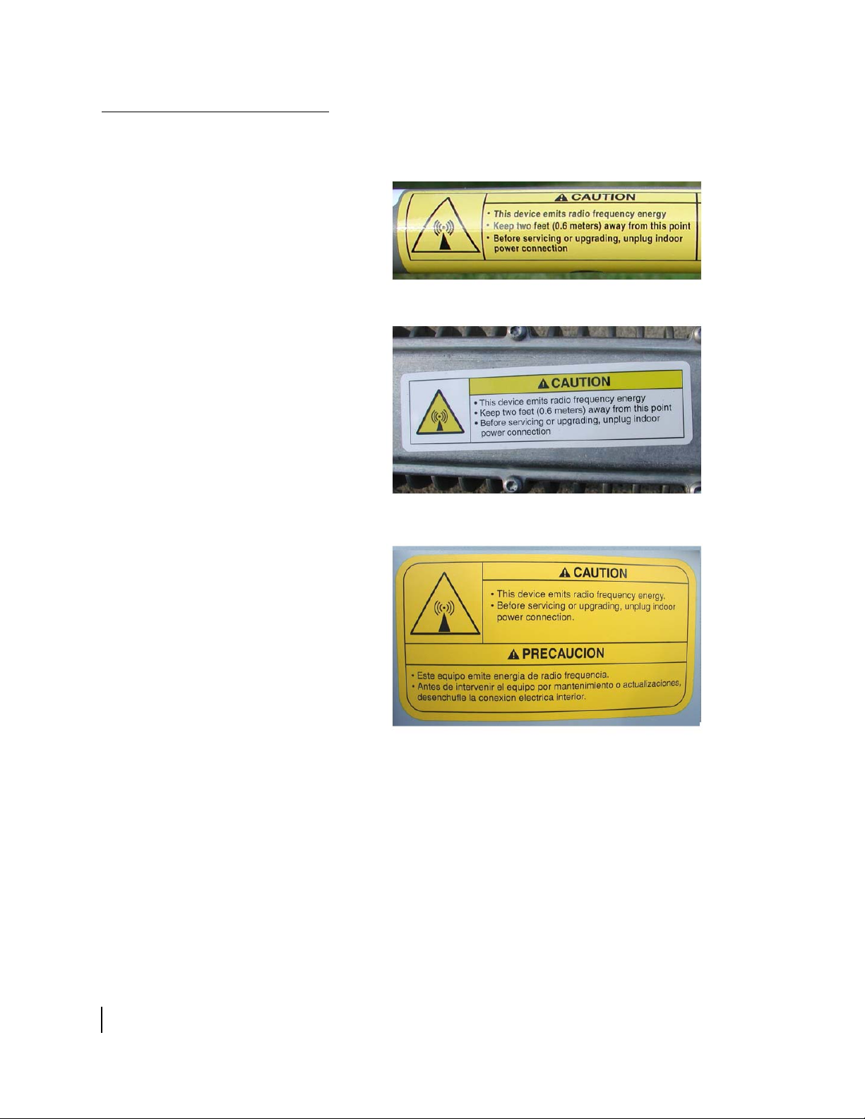
Product warning labels
The following safety alert labels are affixed to the satellite
antenna feed support tube, transmitter, and antenna reflector:
Feed support tube
Transmitter
• Important safety information
iv
1037312-0001 Revision A
Reflector (back side)
Safety alert labels on the antenna assembly
These labels advise that the antenna emits radio frequency (RF)
energy. Because of this potential safety hazard, observe all
cautions on these labels and in the following section (
installation safety) concerning RF radiation.
Antenna
Page 5
Antenna installation safety
Observe the following precautions when installing the satellite
antenna. This manual also includes additional safety alerts where
appropriate concerning specific installation
procedures.
WARNING
Only Hughes-certified installers may install or service
Hughes earth stations and components. Installers must
expressly acknowledge the Hughes requirements for
Hughes installations.
DANGER
If you work on a roof, tower, or other high structure or use a
ladder or scaffold to access the work site, follow these
precautions to prevent personal injury or death:
• Walk only on sound roof structures.
• Make sure the antenna assembly and installation
surface are structurally sound so they can support all
loads (equipment weight, ice, and wind).
• Use appropriate safety equipment (for example, a
lifeline), depending on the work location.
• Follow all safety precautions from the manufacturers of
all safety equipment and other equipment used.
• Perform as many procedures as possible on the ground.
DANGER
• To avoid electric shock, stay at least 20 ft from power
lines.
• If any part of the antenna or mount assembly comes in
contact with a power line, call your local power
company to remove it. Do not try to remove it yourself.
Failure to heed these warnings could result in serious injury
or death.
• Important safety information
1037312-0001 Revision A
v
Page 6

WARNING
• Do not work in high wind or rain or if a storm, lightning,
or other adverse weather conditions are present or
approaching.
• Do not attempt to assemble, move, or mount the
antenna on a windy day. Even a slight wind can
unexpectedly create strong, unexpected forces on the
antenna surface.
• Important safety information
vi
1037312-0001 Revision A
Page 7
CAUTION
Observe these precautions to avoid exposure to RF
radiation, a potential safety hazard:
• The antenna must be installed in a location or manner
not readily accessible to children and in a manner that
prevents human exposure to potentially harmful levels
of radiation.
• Antennas mounted in Puerto Rico, the continental
United States, or at any site with greater than a 30°
elevation angle must be installed such that the lower lip
of the antenna reflector is at least 5 ft above any surface
upon which a person might be expected to stand, and
ft 3 inches from any opening (such as a door or
3
window) in a building or adjacent structure.
• Antennas mounted in Canada, Alaska, Hawaii, or any
site with less than a 30° elevation must be installed
such that the lower lip of the antenna reflector is at least
ft 9 inches above any surface upon which a person
5
might be expected to stand, and 3 ft 3 inches from any
opening (such as a door or window) in a building or
adjacent structure.
• The antenna must be mounted such that no object
which could reasonably be expected to support a
person is within 6 ft 7 inches of the edges of a
cylindrical space projecting outward from the antenna
reflector toward the satellite.
• If the above distance requirements cannot be met, the
antenna must be mounted in a controlled area
inaccessible to the general public, such as a fenced
enclosure or a roof.
• The antenna must be mounted such that there is no
object outside the controlled area which could
reasonably be expected to support a person within
ft 7 inches of the edges of a cylindrical space
6
projecting outward from the antenna reflector toward
the satellite.
• A fenced installation must have a locked entry, and the
fenced area must be large enough to protect the general
public from exposure to potentially harmful levels of
radiation.
• Access to a roof installation in a commercial, industrial,
or institutional environment must be limited by a door or
a permanently fastened ladder that is locked to deny
access to the general public.
Failure to observe these cautions could result in injury to
eyes or other personal injury.
• Important safety information
1037312-0001 Revision A
vii
Page 8
CAUTION
• All installations of any type or size must carry an
industry standard and government approved Radiation
Hazard Caution label on the feed arm.
• A fenced or roof installation in a commercial, industrial,
or institutional environment must carry a Radiation
Hazard Caution sign on the access door, gate, or
permanently mounted access ladder that is within plain
sight of anyone approaching the antenna from the front
or sides of the reflector.
Failure to observe these cautions could result in injury to
eyes or other personal injury.
Some installations may require additional precautions. See also
the HN System Antenna Site Preparation and Mount
Installation Guide (1035678-0001).
viii
• Important safety information
1037312-0001 Revision A
Page 9

Contents
Important safety information . . . . . . . . . . . . . . . . . . . . . iii
Types of warnings used in this manual . . . . . . . . . . . . . . . . . . . iii
Product warning labels . . . . . . . . . . . . . . . . . . . . . . . . . . . . . . . . iv
Antenna installation safety . . . . . . . . . . . . . . . . . . . . . . . . . . . . . .v
About this document . . . . . . . . . . . . . . . . . . . . . . . . . . xvii
Scope and audience . . . . . . . . . . . . . . . . . . . . . . . . . . . . . . . . .xvii
Organization . . . . . . . . . . . . . . . . . . . . . . . . . . . . . . . . . . . . . . .xvii
Related publications . . . . . . . . . . . . . . . . . . . . . . . . . . . . . . . . xviii
Revision record. . . . . . . . . . . . . . . . . . . . . . . . . . . . . . . . . . . . xviii
Chapter 1
Overview . . . . . . . . . . . . . . . . . . . . . . . . . . . . . . . . . . . . . . .1
The model AN6-098P antenna. . . . . . . . . . . . . . . . . . . . . . . . . . .2
Antenna installation summary . . . . . . . . . . . . . . . . . . . . . . . . . . .3
Tasks related to antenna installation . . . . . . . . . . . . . . . . . . . . . .4
Selecting the installation site . . . . . . . . . . . . . . . . . . . . . . . . . .4
Installing the antenna mount . . . . . . . . . . . . . . . . . . . . . . . . . .4
Installing the IDU . . . . . . . . . . . . . . . . . . . . . . . . . . . . . . . . . . .4
Grounding. . . . . . . . . . . . . . . . . . . . . . . . . . . . . . . . . . . . . . . . .4
Approved cables . . . . . . . . . . . . . . . . . . . . . . . . . . . . . . . . . . . .5
Chapter 2
Antenna parts and required tools. . . . . . . . . . . . . . . . . . .7
Antenna kit components. . . . . . . . . . . . . . . . . . . . . . . . . . . . . . . .8
Related components . . . . . . . . . . . . . . . . . . . . . . . . . . . . . . .8
Two antenna kits for two radio types . . . . . . . . . . . . . . . . . . . .8
Inspecting the antenna parts . . . . . . . . . . . . . . . . . . . . . . . . . . .9
Description of main components . . . . . . . . . . . . . . . . . . . . . .10
Az/El and reflector bracket assembly. . . . . . . . . . . . . . . . .10
Antenna reflector . . . . . . . . . . . . . . . . . . . . . . . . . . . . . . . .11
Feed support tube and feed rods. . . . . . . . . . . . . . . . . . . . .12
Feed horn and waveguide transition. . . . . . . . . . . . . . . . . .13
Radio mounting adapter . . . . . . . . . . . . . . . . . . . . . . . . . . .14
Radio mounting brackets (for J-type radio only). . . . . . . .14
Radio assembly types . . . . . . . . . . . . . . . . . . . . . . . . . . . . . . . . .15
J-type radio assembly . . . . . . . . . . . . . . . . . . . . . . . . . . . . .15
Vertical shim kit (if required). . . . . . . . . . . . . . . . . . . . .15
Cradle-type radio assembly . . . . . . . . . . . . . . . . . . . . . . . .16
• Contents
1037312-0001 Revision A
ix
Page 10

Small hardware parts lists. . . . . . . . . . . . . . . . . . . . . . . . . . . . . .18
Additional parts for J-type radio. . . . . . . . . . . . . . . . . . . . . . .19
Tools. . . . . . . . . . . . . . . . . . . . . . . . . . . . . . . . . . . . . . . . . . . . . .20
Chapter 3
Assembling the antenna. . . . . . . . . . . . . . . . . . . . . . . . . .21
Determining the pointing values . . . . . . . . . . . . . . . . . . . . . . . .21
General instructions for assembling the antenna . . . . . . . . . . . .22
Installing the Az/El and reflector bracket assembly. . . . . . . . . . 23
Attaching the reflector . . . . . . . . . . . . . . . . . . . . . . . . . . . . . . . .25
Installing the feed support tube . . . . . . . . . . . . . . . . . . . . . . . . .27
Attaching the feed rods. . . . . . . . . . . . . . . . . . . . . . . . . . . . . .27
Securing the feed support tube . . . . . . . . . . . . . . . . . . . . . . . .28
Tightening the hardware. . . . . . . . . . . . . . . . . . . . . . . . . . . . .29
Chapter 4
Installing a J-type radio assembly . . . . . . . . . . . . . . . . .31
Installing a shim for vertical transmit polarization . . . . . . . . . .32
Installing the radio assembly . . . . . . . . . . . . . . . . . . . . . . . . . . .36
Attaching the upper mounting bracket . . . . . . . . . . . . . . . . . .36
Attaching the feed horn and transition to the radio assembly 37
Mounting the radio assembly on the feed support tube . . . . .39
Chapter 5
Installing a cradle-type radio assembly . . . . . . . . . . . . .43
Installing the radio assembly . . . . . . . . . . . . . . . . . . . . . . . . . . .44
Attaching the feed horn . . . . . . . . . . . . . . . . . . . . . . . . . . . . .44
Mounting the radio assembly on the feed support tube . . . . .45
Setting polarization for the cradle-type radio. . . . . . . . . . . . . . .47
Calculating the radio polarization setting. . . . . . . . . . . . . . . .47
For a horizontal uplink /vertical downlink . . . . . . . . . . . . .47
For a vertical uplink / horizontal downlink. . . . . . . . . . . . .47
Setting the radio polarization . . . . . . . . . . . . . . . . . . . . . . . . .48
Chapter 6
Cabling and connections . . . . . . . . . . . . . . . . . . . . . . . . .49
Previous cabling work . . . . . . . . . . . . . . . . . . . . . . . . . . . . . . . .49
Routing the cables at the ODU. . . . . . . . . . . . . . . . . . . . . . . . . .50
Ground connection . . . . . . . . . . . . . . . . . . . . . . . . . . . . . . . . . . .51
Connecting the transmit and receive cables . . . . . . . . . . . . . . . .52
Transmit cable . . . . . . . . . . . . . . . . . . . . . . . . . . . . . . . . . . . .52
Receive cable . . . . . . . . . . . . . . . . . . . . . . . . . . . . . . . . . . . . .54
• Contents
x
1037312-0001 Revision A
Page 11

Chapter 7
Pointing the antenna . . . . . . . . . . . . . . . . . . . . . . . . . . . .55
Antenna pointing overview . . . . . . . . . . . . . . . . . . . . . . . . . . . .56
Using the installation software . . . . . . . . . . . . . . . . . . . . . . . .56
Peaking the signal (description) . . . . . . . . . . . . . . . . . . . . . . .56
Personnel requirements . . . . . . . . . . . . . . . . . . . . . . . . . . . . .57
Pointing parameters . . . . . . . . . . . . . . . . . . . . . . . . . . . . . . . .57
Prerequisites for antenna pointing . . . . . . . . . . . . . . . . . . . . . . .57
Outdoor pointing interface . . . . . . . . . . . . . . . . . . . . . . . . . . . . .57
Installing the OPI . . . . . . . . . . . . . . . . . . . . . . . . . . . . . . . . . .58
OPI block . . . . . . . . . . . . . . . . . . . . . . . . . . . . . . . . . . . . . .58
Adjusting the antenna. . . . . . . . . . . . . . . . . . . . . . . . . . . . . . . . .59
Adjustment locations on the antenna . . . . . . . . . . . . . . . . . . .60
Setting coarse elevation . . . . . . . . . . . . . . . . . . . . . . . . . . . . . . .61
Fine elevation adjustment. . . . . . . . . . . . . . . . . . . . . . . . . . . . . .62
Receive pointing. . . . . . . . . . . . . . . . . . . . . . . . . . . . . . . . . . . . .62
Initial elevation setting . . . . . . . . . . . . . . . . . . . . . . . . . . . . . .63
Setting polarization. . . . . . . . . . . . . . . . . . . . . . . . . . . . . . . . .63
Setting azimuth. . . . . . . . . . . . . . . . . . . . . . . . . . . . . . . . . . . .64
If you cannot detect a signal. . . . . . . . . . . . . . . . . . . . . . . .65
Peaking the signal (procedure) . . . . . . . . . . . . . . . . . . . . . . . .66
Isolating the transmit signal . . . . . . . . . . . . . . . . . . . . . . . . . . . .67
Manual ACP test. . . . . . . . . . . . . . . . . . . . . . . . . . . . . . . . . . .67
Automatic ACP test . . . . . . . . . . . . . . . . . . . . . . . . . . . . . . . .68
Final steps. . . . . . . . . . . . . . . . . . . . . . . . . . . . . . . . . . . . . . . . . .69
Remove the OPI . . . . . . . . . . . . . . . . . . . . . . . . . . . . . . . . . . .69
Check for safety labels and signs . . . . . . . . . . . . . . . . . . . . . .69
Subsequent steps. . . . . . . . . . . . . . . . . . . . . . . . . . . . . . . . . . .69
Acronyms and abbreviations . . . . . . . . . . . . . . . . . . . . .71
Index . . . . . . . . . . . . . . . . . . . . . . . . . . . . . . . . . . . . . . . . .73
• Contents
1037312-0001 Revision A
xi
Page 12

xii
• Contents
1037312-0001 Revision A
Page 13

Figures
Chapter 1
1. Hughes model AN6-098P .98 m satellite antenna with radio . . . . . . . . . . . . . . .2
Chapter 2
2. Shipping container contents—main components . . . . . . . . . . . . . . . . . . . . . . . . .9
3. Az/El and reflector bracket assembly (pre-assembled as one unit) . . . . . . . . . .10
4. Antenna reflector . . . . . . . . . . . . . . . . . . . . . . . . . . . . . . . . . . . . . . . . . . . . . . . .11
5. Feed support tubes (two types). . . . . . . . . . . . . . . . . . . . . . . . . . . . . . . . . . . . . .12
6. Feed rods (two types) . . . . . . . . . . . . . . . . . . . . . . . . . . . . . . . . . . . . . . . . . . . . .12
7. Feed horn and waveguide transition. . . . . . . . . . . . . . . . . . . . . . . . . . . . . . . . . .13
8. Radio assembly mounting adapter . . . . . . . . . . . . . . . . . . . . . . . . . . . . . . . . . . .14
9. Radio assembly mounting brackets and adapter. . . . . . . . . . . . . . . . . . . . . . . . .14
10. J-type radio assembly . . . . . . . . . . . . . . . . . . . . . . . . . . . . . . . . . . . . . . . . . . . . .15
11. Shim for vertical transmit polarization. . . . . . . . . . . . . . . . . . . . . . . . . . . . . . . .16
12. Cradle-type radio assembly (shown with mounting adapter). . . . . . . . . . . . . . .16
13. Cradle-like rotation of the cradle-type radio assembly . . . . . . . . . . . . . . . . . . .17
Chapter 3
14. Making sure the mast is plumb. . . . . . . . . . . . . . . . . . . . . . . . . . . . . . . . . . . . . .23
15. Az/El and reflector bracket assembly on the mast . . . . . . . . . . . . . . . . . . . . . . .24
16. Reflector in correct position for installation. . . . . . . . . . . . . . . . . . . . . . . . . . . .25
17. Mounting the reflector on the reflector bracket . . . . . . . . . . . . . . . . . . . . . . . . .26
18. Attaching feed rods to the reflector . . . . . . . . . . . . . . . . . . . . . . . . . . . . . . . . . .27
19. Attaching the feed rods to the feed support tube . . . . . . . . . . . . . . . . . . . . . . . .28
20. Attaching the feed support tube to the reflector rim. . . . . . . . . . . . . . . . . . . . . .28
21. Tightening nuts on feed rods and feed support tube. . . . . . . . . . . . . . . . . . . . . .29
22. Completed antenna assembly (without radio) . . . . . . . . . . . . . . . . . . . . . . . . . .29
Chapter 4
23. Shim location next to TRIA . . . . . . . . . . . . . . . . . . . . . . . . . . . . . . . . . . . . . . . .32
24. Horizontal shim and vertical shim for transmit polarization . . . . . . . . . . . . . . .33
25. Direction of TRIA rotation for vertical polarization . . . . . . . . . . . . . . . . . . . . .34
26. TRIA position for horizontal and vertical transmit polarization . . . . . . . . . . . .35
27. Attaching the upper mounting bracket . . . . . . . . . . . . . . . . . . . . . . . . . . . . . . . .36
28. Feed horn with waveguide transition attached . . . . . . . . . . . . . . . . . . . . . . . . . .37
29. O-ring in groove in waveguide transition. . . . . . . . . . . . . . . . . . . . . . . . . . . . . .37
30. Attaching the waveguide transition to the TRIA . . . . . . . . . . . . . . . . . . . . . . . .38
• Figures
1037312-0001 Revision A
xiii
Page 14

31. Securing the feed horn clamp . . . . . . . . . . . . . . . . . . . . . . . . . . . . . . . . . . . . . . .39
32. Attaching the radio assembly to the feed support tube. . . . . . . . . . . . . . . . . . . .40
33. Attaching the radio assembly to the feed support tube. . . . . . . . . . . . . . . . . . . .41
Chapter 5
34. Attaching the feed horn and radio assembly . . . . . . . . . . . . . . . . . . . . . . . . . . .44
35. O-ring in groove . . . . . . . . . . . . . . . . . . . . . . . . . . . . . . . . . . . . . . . . . . . . . . . . .45
36. Mounting the radio on the feed support tube . . . . . . . . . . . . . . . . . . . . . . . . . . .46
37. Rear circular bracket with polarization scale . . . . . . . . . . . . . . . . . . . . . . . . . . .48
Chapter 6
38. Transmit and receive cable configurations. . . . . . . . . . . . . . . . . . . . . . . . . . . . .50
39. Ground screw on J-type radio assembly. . . . . . . . . . . . . . . . . . . . . . . . . . . . . . .51
40. Ground screw on cradle-type radio assembly. . . . . . . . . . . . . . . . . . . . . . . . . . .52
41. Transmit connector – J-type radio . . . . . . . . . . . . . . . . . . . . . . . . . . . . . . . . . . .53
42. Transmit connector – cradle-type radio . . . . . . . . . . . . . . . . . . . . . . . . . . . . . . .53
43. Receive connector – J-type radio . . . . . . . . . . . . . . . . . . . . . . . . . . . . . . . . . . . .54
44. Receive connector – cradle-type radio . . . . . . . . . . . . . . . . . . . . . . . . . . . . . . . .54
Chapter 7
45. OPI (optional pointing tool) . . . . . . . . . . . . . . . . . . . . . . . . . . . . . . . . . . . . . . . .57
46. OPI . . . . . . . . . . . . . . . . . . . . . . . . . . . . . . . . . . . . . . . . . . . . . . . . . . . . . . . . . . .58
47. Adjusting elevation, polarization, and azimuth . . . . . . . . . . . . . . . . . . . . . . . . .59
48. Pointing adjustments on the antenna—elevation, polarization, and azimuth. . .60
49. Setting coarse elevation . . . . . . . . . . . . . . . . . . . . . . . . . . . . . . . . . . . . . . . . . . .61
50. Fine elevation adjustment. . . . . . . . . . . . . . . . . . . . . . . . . . . . . . . . . . . . . . . . . .62
51. Polarization adjustment on the antenna . . . . . . . . . . . . . . . . . . . . . . . . . . . . . . .63
52. Azimuth adjustments on the antenna . . . . . . . . . . . . . . . . . . . . . . . . . . . . . . . . .64
xiv
• Figures
1037312-0001 Revision A
Page 15

Tables
Chapter 2
1. Two antenna kit configurations . . . . . . . . . . . . . . . . . . . . . . . . . . . . . . . . . . . . . .8
2. Small hardware parts used in antenna kits for both radio types . . . . . . . . . . . . .18
3. Additional small hardware parts included in the antenna kit for the
J-type radio assembly . . . . . . . . . . . . . . . . . . . . . . . . . . . . . . . . . . . . . . . . . . . . .19
4. Tools required to install and point the antenna. . . . . . . . . . . . . . . . . . . . . . . . . .20
5. Tool sizes matched to hardware sizes. . . . . . . . . . . . . . . . . . . . . . . . . . . . . . . . .20
Chapter 3
6. Torque specifications . . . . . . . . . . . . . . . . . . . . . . . . . . . . . . . . . . . . . . . . . . . . .22
• Tables
1037312-0001 Revision A
xv
Page 16

xvi
• Tables
1037312-0001 Revision A
Page 17

About this document
Scope and audience
Organization
This manual explains how to assemble, install, and point the
Hughes model AN6-098P
qualified installers who are familiar with satellite antenna
installation practices and are capable of properly applying the
information presented.
This manual is divided into the following chapters and appendix:
• Chapter 1 – Overview includes a summary of the installation
steps and tells you where to find information about tasks
related to antenna installation.
• Chapter 2 – Antenna parts and required tools describes the
parts provided in the antenna kit and tools required for
antenna installation.
• Chapter 3 – Assembling the antenna provides instructions for
assembling and installing the antenna.
• Chapter 4 – Installing a J-type radio assembly provides
instructions for installing the J-type radio assembly.
• Chapter 5 – Installing a cradle-type radio assembly provides
instructions for installing the cradle-type radio assembly.
• Chapter 6 – Cabling and connections provides information
about making connections to the radio assembly.
• Chapter 7 – Pointing the antenna explains how to point the
antenna at the satellite, connect the transmitter, and acquire
the satellite signal.
.98 m antenna. It is written for
An acronyms and abbreviations list and an index are included at
the back of the manual.
• About this document
1037312-0001 Revision A
xvii
Page 18

Related publications
The HN System Antenna Site Preparation and Mount
Installation Guide (1035678-0001) contains detailed information
about:
• Safety considerations for mount and antenna installations
• Site surveys
• Trimasts and other types of antenna mounts
• Antenna installations on various types of surfaces
• Requirements for antennas that will be used in a Ka-band
system or will later be upgraded for use in a Ka-band system
Additional related publications are identified in Tasks related to
antenna installation on page 4.
Revision record
This section describes the revision history of this manual.
Revision Date of issue Scope
A March 2, 2007 Initial release
xviii
• About this document
1037312-0001 Revision A
Page 19

Chapter 1
Overview
This chapter presents an overview of the Hughes model
AN6-098P
• The model AN6-098P antenna on page 2
• Antenna installation summary on page 3
• Tasks related to antenna installation on page 4
.98 m Ku-band antenna in the following sections:
Chapter 1 • Overview
1037312-0001 Revision A
1
Page 20
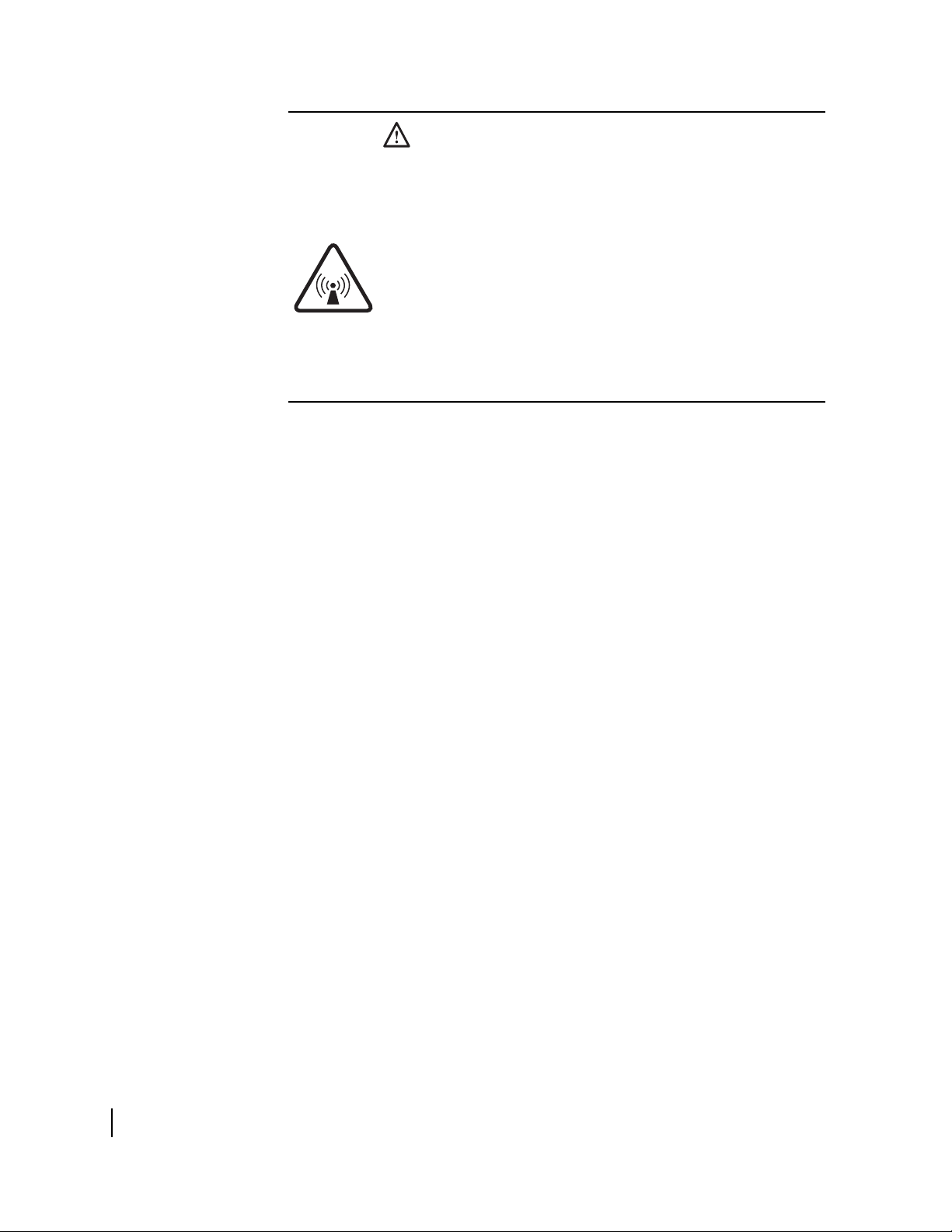
The model AN6-098P antenna
Each remote terminal at a customer site requires an antenna and
radio assembly to communicate with the system satellite and the
Network Operations Center (NOC). The antenna is connected to
the remote terminal (also known as the indoor unit, or IDU) by a
transmit cable and a receive cable.
The Hughes model AN6-098P .98 m Ku-band antenna is
designed for both Ku-band and Ka-band applications.
shows the model AN6-098P antenna, installed, with a radio
assembly.
Figure 1
Chapter 1 • Overview
2
1037312-0001 Revision A
Figure 1: Hughes model AN6-098P .98 m satellite antenna with radio
Page 21

Antenna installation summary
The antenna installation steps and related tasks are summarized
below. The steps in bold type are documented in this manual.
1. Choose an installation site.
2. Select a method for mounting the antenna.
3. Install the antenna mount.
Note: A critical requirement is that the mast must be plumb.
The antenna assembly cannot be adjusted to correct for a mast
that is not plumb.
4. Install the IDU.
Note: Install the IDU before installing the antenna so you
can use the installation software to determine the pointing
values (azimuth, elevation, and polarization).
5. Determine the pointing values (azimuth, elevation,
and polarization) – Chapter 3
6. Install the Az/El and reflector bracket assembly on the
mast – Chapter
3
7. Install the antenna reflector – Chapter 3
8. Install the feed rods and feed support tube – Chapter 3
9. Install the radio assembly –
Chapter 4 (J-type radio) or Chapter 5 (cradle-type radio)
Note: The J-type and cradle-type radio assemblies are
described in
Radio assembly types on page 15.
10. Run cables between the IDU and ODU locations.
11. Ground the antenna assembly.
12. Connect cables to the ODU – Chapter 6
13. Point the antenna – Chapter 7
For the steps not shown in bold type, see the following section,
Tasks related to antenna installation.
Note: Outdoor unit (ODU) refers to the antenna, radio assembly,
and antenna mount.
Follow all steps in the order they are presented. Do not tighten
any hardware until you are instructed to do so.
Chapter 1 • Overview
1037312-0001 Revision A
3
Page 22

Tasks related to antenna installation
This section explains where you can find information on tasks
related to antenna installation.
Selecting the installation
site
Installing the antenna
mount
Factors you should consider in selecting an installation site are
discussed in the HN System Antenna Site Preparation and
Mount Installation Guide (1035678-0001). The installation site
and mounting method may be specified in the customer-specific
installation specification.
A suitable antenna mount must be installed before the antenna
can be installed. Acceptable mounting methods are:
• Non-penetrating mount
• Trimast (may be used on a wood-frame roof or wood or
masonry wall)
• Pole or pedestal mount
Most installations in a commercial, industrial, or institutional
environment use a non-penetrating roof mount.
For pole or pedestal mounts that require a concrete base, you
must allow at least 24 hr for the concrete to cure before you can
install the antenna. Plan accordingly.
For complete information concerning antenna mount installation,
refer to:
• The customer-specific installation specification
• The HN System Antenna Site Preparation and Mount
Installation Guide
Installing the IDU
Chapter 1 • Overview
4
1037312-0001 Revision A
Grounding
The customer-specific installation specification may include
customer-specific guidelines concerning mount installation. Use
only the mounting method described in the specification. For
mount installation instructions, see the HN
Preparation and Mount Installation Guide.
See the installation manual for the IDU (also referred to as a
remote terminal.)
The entire antenna assembly must be grounded. For grounding
information, refer to your training; best grounding practices; the
Hughes Field Service Bulletin (FSB), HNS Broadband
Requirements for RG-6 and RG-11 IFL Cable Connectors,
Ground Blocks and Ground Block Location (FSB 50518_01C);
and applicable parts of the National Electrical Code (NEC).
System Antenna Site
Page 23

Approved cables
For a list of approved cables for the interfacility link (IFL)
between the antenna and the remote terminal, see the Hughes
FSB, IFL Cable, Approved List (with lengths) for DW7x00,
DW60xx, and DW40xx Domestic Installations
(FSB_060316_01A). The FSB lists the maximum cable length
for each approved cable type, for both 1-W and 2-W radios.
How the cable is run depends on the specific installation site.
Route and connect the IFL cable according to your training and
best practices.
Chapter 1 • Overview
1037312-0001 Revision A
5
Page 24

Chapter 1 • Overview
6
1037312-0001 Revision A
Page 25

Chapter 2
Antenna parts and required tools
This chapter describes the parts provided in the model AN6-098P
antenna kit. It includes the following sections:
• Antenna kit components on page 8
• Radio assembly types on page 15
• Small hardware parts lists on page 18
• Too ls on page 20
Chapter 2 • Antenna parts and required tools
1037312-0001 Revision A
7
Page 26

Antenna kit components
Related components The following are related components that are not part of the
This section describes the main components of the .98 m antenna
kit:
• Az/El and reflector bracket assembly
• Antenna reflector
• Feed support tube and feed rods
• Feed horn
• Mounting parts for radio assembly
For details see Description of main components on page 10.
antenna kit:
• Radio assembly (J-type or cradle-type) – See Radio assembly
types on page 15.
• Antenna mount – For general information about antenna
mounts, see
Installing the antenna mount on page 4.
Two antenna kits for two
radio types
You can install the .98 m antenna with either of two radio types,
the J-type radio or cradle-type radio, which are described in
Radio assembly types on page 15.
To support these two radio types, the antenna kit is available in
two configurations, as listed in
Table 1. In this manual, the
antenna kit is used to refer to either kit.
Each antenna kit consists of two boxes of parts, as detailed in
Figure 2. Most parts are common to both antenna kits. The main
parts that are different in the two kits are the feed support tube,
feed rods, and parts used to mount the radio assembly.
Before proceeding, refer to Table 1 and make sure you have the
correct antenna kit.
Table 1: Two antenna kit configurations
Box contents
Antenna kit for J-type radio
Box 1 – Az/El and reflector bracket assembly, feed horn, mounting brackets
and adapter for radio assembly, waveguide transition, and other parts.
Box 2 – Reflector, feed support tube, feed rods, and other parts. P/N 1501111-0002
Antenna kit for cradle-type radio
Box 1 – Az/El and reflector bracket assembly, feed horn, adapter for radio
assembly, and other parts.
Box 2 – Reflector, feed support tube, feed rods, and other parts. P/N 1501111-0022
Box 1 is labeled Box 1 of 2. Box 2 is labeled Box 2 of 2.
Hughes part number
for each box
P/N 1501111-0001
P/N 1501111-0021
Chapter 2 • Antenna parts and required tools
8
1037312-0001 Revision A
Page 27
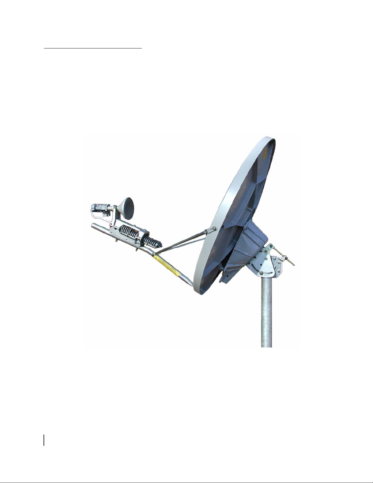
Inspecting the antenna
parts
Box 1 of 2
Az/El and reflector
bracket assembly
Feed horn
Radio mounting adapter
Included in kit for J-type radio only:
Radio mounting brackets
Waveguide transition
(attached to feed horn)
The antenna kit for each radio type is shipped in two boxes, as
shown in
Figure 2. The radio assembly is shipped separately. As
soon as possible, unpack and inspect the antenna parts and
hardware to make sure all parts have been received in good
condition.
Each main part is illustrated in the following sections, and the
small hardware parts are listed in
Tabl e 2 and Ta ble 3 on page 19.
If any parts appear to have been damaged in transit, immediately
contact the freight carrier. If any parts appear to be missing or
damaged but not as a result of handling in transit, contact your
dealer or distributor.
Antenna kit
(2 boxes)
Box 2 of 2
Antenna reflector
Feed support tube
Feed rods
The feed support tube and feed rods in the
two antenna kits, for the J-type or cradletype radio, are not interchangeable.
Small hardware parts such as fasteners are also
included in the boxes, as detailed in Tables 2 and 3.
T0172017
Figure 2: Shipping container contents—main components
Radio
assembly
J-type or cradle-type
Not
part of the antenna kit
Chapter 2 • Antenna parts and required tools
1037312-0001 Revision A
9
Page 28
Description of main
components
The following sections describe and illustrate the antenna
assembly’s main components.
Az/El and reflector bracket
assembly
The Az/El mount assembly and reflector bracket assembly are
pre-assembled for installation as a single unit, as shown in
Figure 3. The Az/El mount assembly supports the antenna and is
used to point the antenna at the satellite. The reflector bracket
supports the antenna reflector.
Reflector
bracket
10
Figure 3: Az/El and reflector bracket assembly (pre-assembled as one unit)
Chapter 2 • Antenna parts and required tools
1037312-0001 Revision A
Az/El mount
assembly
Canister
(slides onto mast)
Page 29

Antenna reflector The antenna reflector is shown in Figure 4.
Figure 4: Antenna reflector
Chapter 2 • Antenna parts and required tools
1037312-0001 Revision A
11
Page 30

Feed support tube and
rods
feed
Tube for
J-type radio
The radio assembly mounts onto the feed support tube (Figure 5).
The feed rods (Figure 6) attach to the reflector and support the
feed support tube.
Each of the two antenna kits contains one feed support tube and
two feed rods, for the radio type supported by the specific antenna
kit.
Figure 5 shows both types of feed support tubes for the two
radio types. The feed support tube for the cradle-type radio is
stamped TG. Other letters or numbers may appear with TG.
g
n
o
l
a
r
Tube for
cradle-type radio
s
e
l
o
h
4
m
o
i
d
a
g
n
ti
n
u
o
e
c
a
f
r
u
s
6 holes along
mounting surface;
5 pass through tube
Figure 5: Feed support tubes (two types)
Figure 6 shows the two types of feed rods for the two radio types.
The rods in the two antenna kits (for each radio type) are different
lengths and are not interchangeable. The feed rods for the
cradle-type radio are stamped TG. Other letters or numbers may
appear with TG.
Rods for
J-type radio
Rods for
cradle-type radio
h
t
g
n
e
l
l
l
a
r
e
ov
s
e
h
c
n
i
5
.
8
2
g
n
e
l
l
l
ra
ve
o
s
e
h
c
n
i
5
.
0
3
Figure 6: Feed rods (two types)
h
t
12
Chapter 2 • Antenna parts and required tools
1037312-0001 Revision A
Page 31

The feed support tube and the feed rods are the only main parts
included in both antenna kits that are different.
Feed horn and waveguide
transition
The feed horn (Figure 7) transmits and receives signals to and
from the reflector.
The J-type radio assembly requires a waveguide transition, as
shown in
Figure 7. In the antenna kit for the J-type radio, the
transition is attached to the feed horn at the factory, as shown in
Figure 7. As explained later in this manual, you attach the
transition the radio assembly.
The antenna kit for the cradle-type radio does not include a
waveguide transition because the feed horn attaches directly to
the cradle-type radio assembly.
Feed horn with
protective packing
material
Waveguide
transition
Figure 7: Feed horn and waveguide transition
CAUTION
• Do not remove the protective packing material from
the feed horn window until installation of the radio
assembly is complete.
• Do not attempt to remove the feed horn window at
any time.
• Be careful not to damage the feed horn window.
Do not touch the plastic film.
Chapter 2 • Antenna parts and required tools
1037312-0001 Revision A
13
Page 32

Radio mounting adapter The mounting adapter shown in Figure 8 is used for both radio
types to mount the radio assembly on the feed support tube.
Figure 8: Radio assembly mounting adapter
Radio mounting brackets
J-type radio only)
(for
The antenna kit for the J-type radio assembly (only) includes two
mounting brackets (
Figure 9) that are used to secure the radio
assembly to the feed support tube, as illustrated in Figure 10 on
page 15.
Upper bracket
Lower bracket
14
Figure 9: Radio assembly mounting brackets and adapter
Chapter 2 • Antenna parts and required tools
1037312-0001 Revision A
Page 33

Radio assembly types
J-type radio assembly Figure 10 shows the J-type radio assembly, referred to as J-type
The radio assembly is not part of the antenna kit; however, radio
assembly installation is included in this manual because the
antenna and radio assembly are usually installed at the same time.
There are two possible radio assemblies available for the
.98 m
antenna, the J-type radio assembly or cradle-type radio assembly.
because its waveguide is shaped something like the letter J.
J-shaped
waveguide
Figure 10: J-type radio assembly
J-type refers to the overall design of the radio; therefore, two
radios with different model numbers may both be J-type radios.
Vertical shim kit (if required)
A vertical transmit shim kit may be required for the J-type radio
assembly only. If the installation specification states that vertical
transmit polarization is required, you will need to obtain and
install a vertical shim kit (
Figure 11) in the radio assembly.
Otherwise, a vertical shim is not required. For more information,
Chapter 2 • Antenna parts and required tools
1037312-0001 Revision A
15
Page 34

see Installing a shim for vertical transmit polarization on
page 32.
Figure 11: Shim for vertical transmit polarization
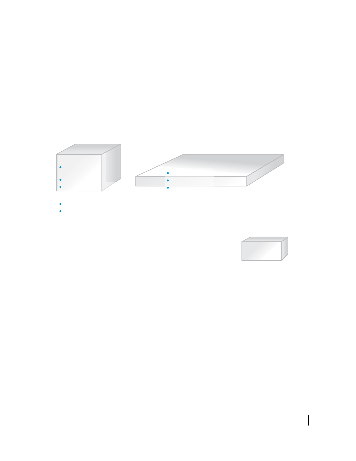
Cradle-type radio assembly Figure 12 illustrates the cradle-type radio assembly. The main
parts of the radio assembly are mounted on two circular brackets
so they can be rotated, similar to the movement of a cradle, to set
the polarization of the feed horn. The arrows in
Figure 13 indicate
how the radio assembly can be rotated.
16
Figure 12: Cradle-type radio assembly (shown with mounting adapter)
Chapter 2 • Antenna parts and required tools
1037312-0001 Revision A
Page 35

Figure 13: Cradle-like rotation of the cradle-type radio assembly
Cradle-type refers to the overall design of the radio; therefore,
two radios with different model numbers may both be cradle-type
radios.
Chapter 2 • Antenna parts and required tools
1037312-0001 Revision A
17
Page 36

Small hardware parts lists
Tables 2 and 3 list the small hardware parts included in the
antenna kits for the two radio types (J-type and cradle-type).
The parts listed in Table 2 are included in both kits, for both radio
assembly types.
Table 2: Small hardware parts used in antenna kits for both radio types
Part Quantity Comments
For assembling the antenna
¼-20 × 1-3/8-inch thread-cutting screws 4 These parts are used for attaching the:
¼-20 × 1-inch hex bolts 3
¼-20 × 2-inch hex bolt 1
¼-inch flat washers 8
¼-inch lock washers 4
¼-inch hex nuts 4
For mounting the radio assembly (both types)
0.9-inch inside diameter O-ring * 1 These parts are used for both radio assemblies, to:
No. 6-32 × 0.5-inch socket-head cap screws * 7
No. 6 internal tooth lock washers * 7
Silicone grease capsule 1
5/16-18 × 2.25-inch carriage bolts 2
5/16-inch flat washers 4
5/16-inch lock washers 4
5/16-inch hex nuts 2
* In the antenna kit for the J-type radio, the waveguide transition is attached to the feed horn at the factory, so
these parts are factory installed.
• Reflector
• Feed rods
• Feed support tube
The hardware for each task is specified in Chapter 3
– Assembling the antenna.
• Attach the feed horn
• Mount the radio assembly
The hardware for each task is specified in:
• Chapter 4 – Installing a J-type radio assembly
• Chapter 5 – Installing a cradle-type radio
assembly
18
Chapter 2 • Antenna parts and required tools
1037312-0001 Revision A
Page 37

Additional parts for
J-type radio
The parts listed in Table 3 are included only in the antenna kit for
the J-type radio. The antenna kit for the J-type radio also includes
the part listed in
Tabl e 2.
Tab le 3 : Additional small hardware parts included in the antenna kit for the J-type radio assembly
Part Quantity Comments
1-inch inside diameter O-ring 1 These parts are used to attach the:
M4 x 12-mm socket-head cap screws 4
M4 lock washers 4
5/16-18 × 1-inch hex bolts 2
¼-20 × 1-inch hex bolts 2
¼-20 × 0.75-inch carriage bolts 4
¼-inch flat washers 4
¼-inch lock washers 6
¼-inch hex nuts 4
Feed horn clamp 1
• Waveguide transition to the radio assembly
• Upper mounting bracket to the transmitter
• Upper and lower mounting brackets to each other
The hardware for each task is specified in Chapter 4
– Installing a J-type radio assembly.
Chapter 2 • Antenna parts and required tools
1037312-0001 Revision A
19
Page 38

Tools
Tabl e 4 lists the tools required to install and point the antenna.
Table 4: Tools required to install and point the antenna
Tool Details
(2) 7/16-inch
combination wrenches *
(2) ½-inch combination
wrenches *
Torque wrench With ½-inch and 7/16-inch sockets capable of torquing to 15 ft-lb.
M7 hex key For J-type radio.
7/64-inch hex key For cradle-type radio. The 7/64-inch hex key is included in the
Long-shaft hexagonal
ball driver, 3-mm
Torque wrench for
hexagonal socket
Bubble level Used to make sure the mast is plumb.
Compass Hand-held, magnetic.
Pencil Carpenter’s pencil.
Outdoor pointing
interface (OPI)
Ladder If needed.
* A socket wrench with 7/16-inch and ½-inch sockets makes some tasks easier, but for some
nuts or bolts there is not enough clearance to use a socket wrench.
For ¼-inch bolts. Some nuts and bolts require a second wrench
to prevent turning.
For 5/16-inch bolts. Two of the canister nuts are not accessible
with a socket wrench. Some nuts and bolts require a second
wrench to prevent turning.
antenna kit.
For socket-head cap screws (Allen screws) with a 3-mm
hexagonal socket. Driver shaft should be at least 5 inches long.
(Recommended for attaching or removing the J-type radio
assembly to or from the waveguide transition. A short-arm hex
key is provided with the screws, but the long-shaft ball driver is
much easier. The long-shaft ball driver cannot be used for the
cradle-type radio.)
Must fit a 3-mm hexagonal socket and be capable of torquing to
15 inch-lb.
Optional. Hughes P/N 1031393-0002. Portable repeater that
displays signal strength values during antenna pointing. For
additional information, see
Installing the OPI on page 58.
20
See the HN System Antenna Site Preparation and Mount
Installation Guide (1035678-0001) for a more complete list of
tools and items that may be needed for installation.
Tabl e 5 specifies the correct tool size for each hardware size
included in the antenna kit:
Chapter 2 • Antenna parts and required tools
1037312-0001 Revision A
Table 5: Tool sizes matched to hardware sizes
Hardware size Tool size
¼-inch 7/16-inch
5/16-inch ½-inch
#6-32 socket-head cap screw 7/64-inch hex key
M4 x 20 mm screw M7 key wrench
Page 39

Chapter 3
Assembling the antenna
This chapter explains how to install:
• The Az/El and reflector bracket assembly – The Az/El
mount assembly and reflector bracket assembly are
pre-assembled for installation as a single unit, as shown in
Figure 3 on page 10.
• The antenna reflector
• The feed rods and feed support tube – The feed rods attach
to the reflector and help support the feed support tube.
Radio installation is covered in Chapter 4 for the J-type radio and
Chapter 5 for the cradle-type radio.
Topics in this chapter include:
• Determining the pointing values on page 21
• General instructions for assembling the antenna on page 22
• Installing the Az/El and reflector bracket assembly on
page 23
• Attaching the reflector on page 25
• Installing the feed support tube on page 27
Determining the pointing values
CAUTION
Before you install the antenna, read all safety information in
the section titled
Satellite-based commissioning (SBC) is an automated web-based
method for pointing the antenna. SBC configures the IDU,
calculates its exact location, and uses the location and other
information to help you point the antenna. SBC calculates the
values you use to set the antenna’s azimuth, elevation, and
polarization, based on the information you enter and the satellite
you select. It then downloads the necessary software and
completes the IDU registration process.
Important safety information on page iii.
Chapter 3 • Assembling the antenna
1037312-0001 Revision A
21
Page 40

In this manual, installation software refers to installation,
pointing, and commissioning software accessed through the IDU,
which works in conjunction with SBC.
Before proceeding, use the installation software to determine the
initial values to use for setting azimuth, elevation, and
polarization. Record these values and keep them handy for
reference as you install and point the antenna. To use the
installation software, follow the instructions in the IDU
installation manual for commissioning the IDU.
General instructions for assembling the antenna
Before you assemble the antenna, read these important
instructions:
• Mast – The mast must be installed before you can install the
antenna. For information on antenna mounting methods, see
the HN System Antenna Site Preparation and Mount
Installation Guide (1035678-0001). The mast must have an
3
outside diameter of 2-
⁄8 inches (2.375 inches).
• Sequence of steps – When you assemble the antenna, follow
the instructions in this chapter in the order they are
presented.
• Tightening hardware– Do not tighten any nuts or other
hardware until you are instructed to do so. (See also the next
item, Torque.)
• Torque – To ensure successful installation of the antenna, you
must tighten all nuts and socket-head cap screws to the
maximum torque values shown in
Tabl e 6. This is a critical
requirement.
Table 6: Torque specifications
Fastener
¼-inch bolts 6 ft-lb
5/16-inch bolts 15 ft-lb
¼-20 thread-cutting screws used to
secure reflector bracket to reflector
No. 6-32 and M4 socket-head cap
screws
Maximum
torque
10 ft-lb
15 inch-lb
22
Chapter 3 • Assembling the antenna
1037312-0001 Revision A
For bolts that use a split lock washer, tighten the bolt until the
washer is flattened, but do not tighten the bolt further. When
the washer is flattened, this indicates that sufficient torque
has been applied.
Page 41

Installing the Az/El and reflector bracket assembly
Bubble must be centered
between marks.
Follow these steps to install the Az/El and reflector bracket
assembly onto the mast:
1. Before you install the Az/El and reflector bracket assembly
onto the mast pipe, use a bubble level to make sure the mast is
plumb.
Check the mast at two perpendicular locations, as shown in
Figure 14.
Note: The mast must be plumb. The antenna assembly
cannot be adjusted to correct for a mast that is not plumb.
To make sure the mast is
plumb, check with the level
in two positions at right
angles to each other.
Mast
Level
Bubble
level
Mast
2nd level
position
Top view
Side view
Figure 14: Making sure the mast is plumb
T0172005
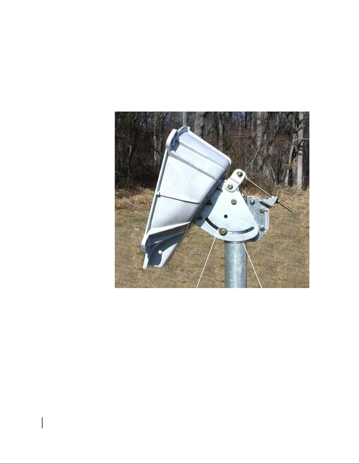
2. Slide the canister of the Az/El and reflector bracket assembly
down onto the mast.
Figure 15 shows the Az/El and reflector bracket assembly on
the mast.
Note: The mast must have an outside diameter of
3
2-
⁄8 inches (2.375 inches).
Chapter 3 • Assembling the antenna
1037312-0001 Revision A
23
Page 42

Top canister nut
(1 of 3)
Reflector
bracket
Az/El mount
assembly
Figure 15: Az/El and reflector bracket assembly on the mast
3. Optional: If you adjust the antenna elevation now to the
coarse elevation value, before installing the reflector, it’s
easier than making this adjustment after the reflector is
attached. You can make this adjustment now or do it as part
of the antenna pointing procedure. (See
Setting coarse
elevation on page 61.)
4. Rotate the Az/El and reflector bracket assembly until the
reflector side is oriented in the general direction of the
satellite.
If necessary, loosen the canister nuts just enough to allow the
assembly to rotate.
5. Snug the three canister nuts just enough to prevent the
assembly from rotating. Do not tighten the nuts at this time.
24
Chapter 3 • Assembling the antenna
1037312-0001 Revision A
Page 43

Attaching the reflector
Follow these instructions to attach the antenna reflector to the
reflector bracket.
Note: This task is easier if someone assists you.
1. Orient the reflector so the HughesNet logo on the front is
near the top, as shown in
Figure 16.
Hole for
attaching
feed rod
Hole for attaching
feed support tube
Figure 16: Reflector in correct position for installation
Hole for
attaching
feed rod
2. Lift the reflector and align the four mounting holes on the
back of the reflector with the four mounting holes on the
reflector bracket. See
Note: To make it easier to position the reflector and insert
the screws (steps
Az/El and reflector bracket assembly beyond the 80° mark on
the elevation scale so the surface of the reflector bracket that
attaches to the reflector is nearly horizontal. Then you can lay
the reflector on the bracket, with the holes in the reflector
facing the bracket. This method (not illustrated here) is
especially useful when one person installs the antenna.
To use this method you must loosen the fine elevation
adjustment nuts and elevation lockdown bolts identified in
Figure 48 on page 60. Be sure to tighten the elevation
lockdown bolts before laying the reflector on the bracket.
Figure 17.
2 and 3), you can adjust the elevation of the
Chapter 3 • Assembling the antenna
1037312-0001 Revision A
25
Page 44

Reflector attached to bracket
Arrows above point to mounting screws. One screw,
indicated by the gray arrow, is not visible in this photo.
Figure 17: Mounting the reflector on the reflector bracket
Mounting holes (arrows)
on back of reflector
3. Insert two ¼-20 × 1-
3
⁄8-inch hex thread-cutting screws
(without washers) through the upper holes on the reflector
bracket and into the reflector holes indicated in
Figure 17
(upper arrows on the right photo).
4. Partially tighten the screws.
5. Insert two ¼-20 × 1-
1
⁄16-inch hex thread-cutting screws
(without washers) through the lower holes on the reflector
bracket and into the lower reflector holes.
6. Tighten each screw a little; then move on to the next screw.
7. Use a torque wrench to tighten the screws to 10 ft-lb force
maximum.
CAUTION
To avoid damaging the mounting holes in the back of the
reflector, do not overtighten the reflector bracket screws.
Use a torque wrench.
26
Chapter 3 • Assembling the antenna
1037312-0001 Revision A
Page 45

Installing the feed support tube
Install the feed rods and feed support tube as explained in the
following two sections. These instructions apply to both types of
feed support tubes and feed rods, that is, the tube and feed rods
for the J-type radio or cradle-type radio.
Note: If you are installing an antenna that will use a cradle-type
radio assembly, make sure the feed support tube and feed rods are
stamped TG. (Other letters or numbers may appear with TG.) If
these parts are not stamped TG, they are the wrong parts for the
cradle-type radio. Contact Installer Support to obtain the correct
parts.
Attaching the feed rods
Attach the feed rods to the reflector:
1. Attach the feed rods to the rim of the reflector as shown in
Figure 18.
The feed rod end with the longer flat part attaches to the
reflector rim; the end with the shorter flat part attaches to the
feed support tube (as shown in
Figure 19 on page 28).
Point the lower end of each feed rod inward, toward the space
in front of the lower part of the reflector. When both feed rods
are correctly installed, their lower ends are just a few inches
apart.
¼-inch
flat washer
¼-20 x 1-inch
hex bolt
Feed rod
¼-inch
flat washer
Reflector
rim
¼-inch lock
washer
¼-inch hex nut
T0172006
Detail – Attaching left feed rod
(right rod – same but opposite)
Figure 18: Attaching feed rods to the reflector
Note: The photos in this section show the feed support tube
and rods for the J-type radio. These parts for the cradle-type
radio are very similar and are installed in the same way.
2. Tighten each nut just enough to keep the hardware in place.
Chapter 3 • Assembling the antenna
1037312-0001 Revision A
27
Page 46

Securing the feed support
tube
Secure the feed support tube:
1. Attach the lower ends of the feed rods to the feed support
tube as follows: Insert the ¼-20 × 2-inch hex bolt through the
tube, and use the hardware shown in
Figure 19.
Make sure the flat end of the feed support tube points toward
the reflector.
2. Tighten the nut just enough to keep the hardware in place.
Feed
support
tube
Feed rodFeed rod
Feed rod ends attached to feed
support tube, in front of reflector
Figure 19: Attaching the feed rods to the feed support tube
Back of
reflector
Rim
3. Attach the flat end of the feed support tube to the rim of the
4. Tighten the nut just enough to keep the hardware in place.
Flat end of feed
support tube
¼-20 x 2-inch
hex bolt
¼-inch
flat washer
reflector, as shown in
¼-inch hex nut
¼-inch lock washer
¼-inch flat washer
Reflector rim
¼-inch flat washer
flat washer
Detail
Figure 20.
¼-20 x 1-inch
hex bolt
Detail
¼-inch
¼-inch hex nut
¼-inch lock
washer
T0172007
Feed
support
tube
Side view
T0172008
28
Figure 20: Attaching the feed support tube to the reflector rim
Chapter 3 • Assembling the antenna
1037312-0001 Revision A
Page 47

Tightening the hardware
Tighten the hardware as follows:
1. Tighten the three nuts on the reflector rim (indicated by the
black arrows in
Figure 21).
2. Tighten the nut where the feed rods attach to the feed support
tube (indicated by the white arrow in
Figure 21: Tightening nuts on feed rods and feed support tube
Figure 21).
The antenna is now assembled, as shown in Figure 22, and ready
for installation of the radio assembly.
• If you are installing a J-type radio, go to Chapter 4 –
Installing a J-type radio assembly, on page 31.
• If you are installing a cradle-type radio, go to Chapter 5 –
Installing a cradle-type radio assembly, on page 43.
Figure 22: Completed antenna assembly (without radio)
Chapter 3 • Assembling the antenna
1037312-0001 Revision A
29
Page 48

30
Chapter 3 • Assembling the antenna
1037312-0001 Revision A
Page 49

Chapter 4
Installing a J-type radio assembly
This chapter applies to the J-type radio assembly only. If you are
installing a cradle-type radio assembly, go to
Installing a cradle-type radio assembly, on page 43.
This chapter includes:
• Installing a shim for vertical transmit polarization on
page 32
• Installing the radio assembly on page 36
CAUTION
• Do not remove the protective packing material from the
feed horn window until installation of the radio
assembly is complete.
• Do not remove the protective covering from the small
end of the feed horn until you are ready to attach the
waveguide transition.
• Be careful not to damage the feed horn window. Do not
touch the plastic film.
Chapter 5 –
Chapter 4 • Installing a J-type radio assembly
1037312-0001 Revision A
31
Page 50

Installing a shim for vertical transmit polarization
Follow the instructions in this section only if the installation
specification or service order states that vertical transmit
polarization is required. (The vertical shim kit is not used with
the cradle-type radio.)
If vertical transmit polarization is not required, go to Installing
the radio assembly on page 36.
The radio assembly is shipped with a horizontal transmit
polarization shim installed. If vertical transmit polarization is
required, you must remove the horizontal shim and replace it with
a vertical transmit polarization shim.
Note: If you need to change from horizontal to vertical transmit
polarization on an antenna that has the radio assembly already
installed on the feed support tube, you will have to remove the
radio assembly from the feed support tube before you can follow
the instructions in this section.
Figure 23 shows where the shim is located and shows three of the
four Allen screws that hold the shim in place.
TRIA
Shim
(See also
Figure 24.)
Allen screws
(4 total)
Figure 23: Shim location next to TRIA
Waveguide
To replace the horizontal shim with a vertical shim, follow these
steps:
1. Obtain a vertical transmit polarization shim kit (Hughes
model VTX-SHIM-KIT, P/N 1033809-0001).
Figure 24 on page 33 shows what a vertical shim looks like.
2. Loosen and remove the four Allen screws that hold the shim
in place. See
Figure 23.
3. Separate the end of the waveguide from the shim.
32
Chapter 4 • Installing a J-type radio assembly
1037312-0001 Revision A
Page 51

X here identifies horizontal shim. This X
is visible when the parts are assembled.
Figure 24 illustrates the difference between the horizontal
shim and vertical shim. Note the positions of the alignment
pins.
TRIA
Horizontal shim in place
O-ring
Horizontal shim
Figure 24: Horizontal shim and vertical shim for transmit polarization
Vertical shim in place
(In this photograph, the TRIA
has not yet been rotated.)
“ – ” mark here identifies vertical shim. This
mark is visible when the parts are assembled.
Alignment
pins
Alignment
pins
Ver ti c a l s h i m
4. Remove the horizontal shim and O-ring.
Chapter 4 • Installing a J-type radio assembly
1037312-0001 Revision A
33
Page 52

5. Install the vertical shim and O-ring in the same location.
Because of its shape and alignment pins on the
transmit/receive isolation assembly (TRIA), the vertical shim
can only be installed in the position shown in
Figure 24
(upper right photo). Note the position of the alignment pins.
Likewise, the horizontal shim can only be installed in one
position.
Because of the shim’s alignment pins, you must rotate the
TRIA 90
° from its horizontal polarization position. You must
rotate the TRIA before you re-attach the waveguide end so
you can insert the shim alignment pins into the waveguide
end plate. See Figures
25 and 26.
Figure 25: Direction of TRIA rotation for vertical polarization
34
Chapter 4 • Installing a J-type radio assembly
1037312-0001 Revision A
Page 53

Figure 26 shows how the TRIA is positioned for horizontal
transmit polarization compared to how it is positioned for
vertical transmit polarization.
Horizontal polarization
TRIA
TRIA
TRIA rotated for vertical polarization
Figure 26: TRIA position for horizontal and vertical transmit
polarization
6. Make sure the O-ring shown in Figure 25 on page 34 is in
place in the shim.
7. With the TRIA correctly positioned (rotated), place the
waveguide end plate against the shim.
8. Insert and tighten the four Allen screws.
At this point the radio assembly is ready to be installed.
Chapter 4 • Installing a J-type radio assembly
1037312-0001 Revision A
35
Page 54

Installing the radio assembly
This section explains how to install the J-type radio assembly.
You must use the antenna kit indicated in
Tabl e 1 on page 8 for
the J-type radio assembly.
Attaching the upper
mounting bracket
Note: The transmitter may look a little
different than the one shown here.
Attach the upper mounting bracket to the transmitter:
1. Place the upper mounting bracket onto the transmitter, in the
position shown in
Figure 27.
Align the two bolt holes in the bracket with the holes in the
transmitter.
2. Secure the bracket to the transmitter with two
5
⁄16-18 × 1-inch
hex bolts, lock washers, and flat washers.
3. Tighten the bolts.
Mounting
bracket
Figure 27: Attaching the upper mounting bracket
Bolts
Transmitter
36
Chapter 4 • Installing a J-type radio assembly
1037312-0001 Revision A
Page 55

Attaching the feed horn and
transition to the radio
assembly
The feed horn and waveguide transition are shipped from the
factory pre-attached, as shown in
Waveguide
transition
O-ring
groove
Figure 28: Feed horn with waveguide transition attached
Figure 28.
Attach the square end of the waveguide transition (with the feed
horn attached) to the radio assembly—specifically, to the
transmit/receive isolation assembly, or TRIA:
1. Apply silicone grease to the O-ring groove in the waveguide
transition. See
Figure 29.
The silicone grease is provided in a small plastic capsule.
2. Place the O-ring (1-inch inside diameter) in the O-ring
groove in the square end of the waveguide transition.
Note: The O-ring and small hardware for the square end of
the waveguide transition are shipped in a bag that contains
four socket-head cap screws.
O-ring
Figure 29: O-ring in groove in waveguide transition
Chapter 4 • Installing a J-type radio assembly
1037312-0001 Revision A
37
Page 56

3. Place the neck of the feed horn into the upper mounting
bracket, and position the square end of the waveguide
transition close to the TRIA. See
Make sure the feed horn packing material is out of the way so
it will not get stuck between the feed horn neck and the upper
mounting bracket.
4. Attach the square end of the waveguide transition to the
TRIA using the provided M4 × 12-mm socket-head cap
screws and M4 lock washers with teeth on the inner edges.
Figure 30.)
(See
Insert the screws in the direction indicated by the white
arrows in
Make sure the O-ring remains in the O-ring groove.
White arrows indicate
location of cap screws and
direction to insert them.
Radio assembly
(TRIA)
Figure 30.
A fourth
cap screw
is not
visible
here.
Figure 30.
Feed
horn
38
Figure 30: Attaching the waveguide transition to the TRIA
5. Use a long-shaft 3-mm ball driver to tighten the M4 cap
screws.
6. Place the feed horn clamp over the neck of the feed horn, as
shown in
7. Insert two ¼-20 × 1-inch hex bolts (with lock washers)—one
on each side of the clamp.
Make sure the packing material is out of the way so it will not
get stuck under the clamp.
Chapter 4 • Installing a J-type radio assembly
1037312-0001 Revision A
Figure 31.
Page 57

8. Tighten the bolts alternately, a little at a time.
Figure 31: Securing the feed horn clamp (arrow)
Mounting the radio
assembly on the feed
support tube
To mount the radio assembly on the feed support tube, first mount
the lower mounting bracket on the feed support tube:
1. Position the lower mounting bracket and mounting adapter on
the feed support tube, with the bolt holes aligned, as shown in
Figure 32.
There are four holes on the top surface of the feed support
tube. Two of these holes are oval slots. Use the round hole
and oval slot closest to the reflector to mount the radio.
(See Figure 32.)
2. Insert two
5
⁄16-18 × 2.5-inch carriage bolts from above, one
into each of the two mounting holes.
3. From below, place a
5
⁄16-inch flat washer, lock washer, and
hex nut on each bolt.
Chapter 4 • Installing a J-type radio assembly
1037312-0001 Revision A
39
Page 58

4. Tighten the nuts.
5/16-18 x 2.5-inch
carriage bolts
Match round hole
in adapter to round
hole in tube.
Match oval slot in adapter
to oval slot in tube.
T0172015
Lower mounting bracket
Mounting adapter
Feed support tube
Figure 32: Attaching the radio assembly to the feed support tube
Attach the upper and lower mounting brackets to each other, as
shown in
Figure 33:
1. Place the radio assembly (attached to the upper bracket in
previous steps) onto the lower bracket.
2. Align the four mounting holes on the upper and lower
mounting brackets.
3. Insert a ¼-20 × 0.75-inch carriage bolt through each of the
four mounting holes.
4. From below, place a ¼-inch flat washer, lock washer, and hex
nut on each bolt.
40
Chapter 4 • Installing a J-type radio assembly
1037312-0001 Revision A
Page 59

5. Tighten the four bolts.
1/4-20 x 0.75-inch
carriage bolts
Upper
mounting
bracket
T0172018
Figure 33: Attaching the radio assembly to the feed support tube
6. Remove the protective packing material from the feed horn
window.
This completes installation of the radio assembly.
Chapter 4 • Installing a J-type radio assembly
1037312-0001 Revision A
41
Page 60

42
Chapter 4 • Installing a J-type radio assembly
1037312-0001 Revision A
Page 61

Chapter 5
Installing a cradle-type radio assembly
This chapter applies to the cradle-type radio assembly only. If
you are installing a J-type radio assembly, go to
Installing a J-type radio assembly, on page 31.
This chapter includes:
• Installing the radio assembly on page 44
• Setting polarization for the cradle-type radio on page 47
CAUTION
• Do not remove the protective packing material from the
feed horn window until installation of the radio
assembly is complete.
• Be careful not to damage the feed horn window. Do not
touch the plastic film.
Chapter 4 –
Chapter 5 • Installing a cradle-type radio assembly
1037312-0001 Revision A
43
Page 62

Installing the radio assembly
This section explains how to install the cradle-type radio
assembly. You must use the antenna kit indicated in
Tabl e 1 on
page 8 for the cradle-type radio assembly.
Attaching the feed horn
7. To attach the feed horn to the radio assembly, refer to Figures
34 and 35 and follow steps 1 through 3 below.
Screws and
washers
Feed horn
O-ring
Figure 34: Attaching the feed horn and radio assembly
T0172013
1. Remove the protective covering from the small end of the
feed horn.
CAUTION
• If you do not remove the protective covering from the
small end of the feed horn, the system may operate, but
with degraded performance.
• Do not remove the protective packing material from the
feed horn window until you finish installation of the
radio assembly.
44
Chapter 5 • Installing a cradle-type radio assembly
1037312-0001 Revision A
Page 63

2. Apply silicone grease to the O-ring groove in the feed horn.
3. Place the O-ring (0.9-inch inside diameter) in the groove.
Note: The O-ring is shipped in a bag that contains seven
socket-head cap screws for attaching the feed horn. Six screws
are required; one is an extra part.
Make sure the O-ring remains in the O-ring groove.
O-ring
Figure 35: O-ring in groove
Mounting the radio
assembly on the feed
support tube
Use the mounting adapter to attach the radio assembly to the feed
support tube. Refer to
Figure 36 as you follow these instructions:
1. Place the mounting adapter and radio assembly onto the feed
support tube.
2. Align the mounting holes in the base of the radio assembly,
mounting adapter, and feed support tube.
There are six holes on the top surface of the feed support
tube. Use the oval slot at the end of the tube and the second
hole from the bend in the tube, as shown in
3. From below, insert two
5
⁄16-inch lock washer and flat washer on each bolt) through
5
⁄16-18 × 2.25-inch hex bolts (using a
Figure 36.
the feed support tube, adapter, and base.
Chapter 5 • Installing a cradle-type radio assembly
1037312-0001 Revision A
45
Page 64

4. Tighten the bolts securely.
Match oval slot in
adapter to oval slot at
the end of the tube.
Match round hole in adapter to
second hole from bend in tube.
T0172014
Figure 36: Mounting the radio on the feed support tube
5. Remove the protective packing material from the feed horn
This completes installation of the radio assembly.
window.
5/16-18 2.5-inch
×
hex bolts
Mounting adapter
Feed support tube
46
Chapter 5 • Installing a cradle-type radio assembly
1037312-0001 Revision A
Page 65

Setting polarization for the cradle-type radio
To set polarization for the cradle-type radio, you adjust the radio,
not the antenna. This section explains how to calculate and set the
polarization value for the cradle-type radio assembly.
Calculating the radio
polarization setting
For a horizontal
uplink
/vertical downlink
To calculate the polarization setting, refer to the section for the
type of uplink and downlink that will be used. In these
instructions, SBC initial value refers to the polarization value
calculated by the installation software.
To calculate the radio polarization setting for a horizontal
/ vertical downlink:
uplink
1. Multiply the SBC initial value by –1,
then offset the result by 90° as follows:
If the SBC initial value is positive, add 90.
If the SBC initial value is negative, subtract 90.
Example 1, positive initial value of 41°
41 × –1 = –41
Add 90:
–41 + 90 = 49
Radio polarization setting = 49°
Example 2, negative initial value of –41°
–41 × –1 = 41
Subtract 90:
41 – 90 = –49
Radio polarization setting = –49°.
For a vertical uplink /
horizontal downlink
2. Make a note of the setting.
3. Go to Setting the radio polarization on page 48.
To calculate the radio polarization setting for a vertical
uplink
/ horizontal downlink:
1. Multiply the SBC initial value by –1 (with no offset).
Example 1, SBC initial value of 38°
38 × –1 = –38
Radio polarization setting = –38°.
Example 1, SBC initial value of 38°
–38 × –1 = 38
Radio polarization setting = 38°.
2. Make a note of the setting.
3. Go to Setting the radio polarization on page 48.
Chapter 5 • Installing a cradle-type radio assembly
1037312-0001 Revision A
47
Page 66

Setting the radio
polarization
Set polarization on the cradle-type radio as follows:
1. Before proceeding, make sure the antenna polarization is set
to 0°. See
Setting polarization on page 63.
2. On the radio assembly, loosen the two screws at the top of the
two circular brackets at each end of the transmitter. (Each of
these brackets has a polarization scale.) See
Screw
Figure 37.
Positive
polarization
scale
Figure 37: Rear circular bracket with polarization scale
Negative
polarization
scale
3. Set the radio polarization to the calculated setting by rotating
the radio and using the polarization scales on the circular
brackets.
Plus ( + ) and ( – ) minus signs at the top of each scale
indicate positive or negative values. Make sure you read the
correct scale.
4. Tighten the two screws on the circular bracket.
This completes installation of the radio assembly.
To set polarization, align marker
indicated by black arrow to the
desired value on the scale. The
setting in this photo is close to 0
°.
48
Chapter 5 • Installing a cradle-type radio assembly
1037312-0001 Revision A
Page 67

Chapter 6
Cabling and connections
This chapter illustrates where the ODU ground, transmit, and
receive connectors are located; shows how to route the transmit
and receive cables at the ODU; and explains how to connect the
transmit and receive cables to the radio assembly. You must
connect the transmit, receive, and ground cables before you can
point the antenna (
The chapter includes these sections:
• Previous cabling work on page 49
• Routing the cables at the ODU on page 50
• Ground connection on page 51
• Connecting the transmit and receive cables on page 52
Chapter 7 – Pointing the antenna).
Previous cabling work
Before you can complete the steps explained in this chapter, you
must route and terminate the transmit and receive cables from the
IDU to the ODU.
For a list of approved cables for the IFL between the antenna and
the remote terminal, see the Field Service Bulletin (FSB), IFL
Cable, Approved List (with lengths) for DW7x00, DW60xx, and
DW40xx Domestic Installations (FSB_060316_01A). This FSB
lists the maximum cable length for each approved cable type, for
both 1-W and 2-W radios.
How the cables are run depends on the specific installation site.
Route and connect the cables according to your training and best
practices.
CAUTION
Coaxial connectors and cable can corrode if exposed to
moisture. Use only compression type connectors, and
weatherproof them with dielectric grease and weatherproof
tape.
Note: For connector requirements, see the Hughes FSB,
HNS Broadband Requirements for RG-6 and RG-11 IFL
Cable Connectors, Ground Blocks and Ground Block
Location (FSB 50518_01C).
Chapter 6 • Cabling and connections
1037312-0001 Revision A
49
Page 68

Routing the cables at the ODU
Do not exceed the
cable bending radius.
Secure cables with
cable ties (not shown).
Route the coaxial transmit and receive cables at the ODU as
follows:
1. Route the transmit cable (marked with blue electrical tape)
over the Az/El and reflector bracket assembly and behind the
reflector to the back of the transmitter, in a configuration
similar to that shown in
Figure 38.
Do not exceed the minimum bending radius specified by the
cable manufacturer.
Transmit cable
(marked with
BLUE tape)
Radio
Transmitter
Receive cable
(marked with
RED tape)
50
T0172016
Figure 38: Transmit and receive cable configurations
Chapter 6 • Cabling and connections
1037312-0001 Revision A
Service loops for transmit and
receive cables. Coiled, with drip loops.
2. For the transmit cable, leave a 152-inch service loop (12 ft
inches), secured to the mast, or Az/El mount assembly. This
8
allows 10 ft for a service loop plus 32 inches for installation
of a future Ka-band radio upgrade.
Do not leave the service loop on the roof or other mounting
surface.
Do not block access to the adjustment nuts on the canister
and Az/El mount assembly.
Page 69

3. Coil the extra cable, leave a drip loop, and secure the transmit
cable with cable ties.
4. Route the receive cable (marked with red electrical tape) over
the Az/El mount assembly, behind the reflector, and along the
feed support tube to the TRIA, in a configuration similar to
that shown in
Figure 38.
Do not exceed the minimum cable bending radius.
5. For the receive cable, leave a 138-inch service loop (11.5 ft),
secured to the mast, Az/El mount assembly, or reflector
bracket. This allows 10
ft for a service loop plus 18 inches for
installation of a future Ka-band radio upgrade.
6. Coil the extra cable, leave a drip loop, and secure the receive
cable with cable ties.
Note: When you connect the cables, tighten all radio and
ground block connectors with a torque wrench to 20
inch-lb.
Ground connection
Ground the transmitter and mast. For specific grounding
procedures, refer to the sources listed in
Grounding on page 4.
Figure 39 shows the location of the ground screw on the J-type
radio assembly. Figure 40 shows the ground screw on the
cradle-type radio assembly.
(Not used)
Figure 39: Ground screw on J-type radio assembly (arrow)
Note: The transmitter may look a little different than the one
shown in
transmitter, as shown, and they are clearly marked: GND – ground.
IFL – interfacility link, for transmit cable.
Figure 40, but the connectors are still on the end of the
Chapter 6 • Cabling and connections
1037312-0001 Revision A
51
Page 70

(Not used)
Figure 40: Ground screw on cradle-type radio assembly (arrow)
Connecting the transmit and receive cables
Transmit cable
This section explains how to connect the transmit and receive
cables to the radio assembly.
Connect the transmit cable to the transmitter as follows:
1. From inside the building, disconnect the IDU power supply.
2. Go outside and connect the transmit cable (marked with blue
electrical tape) to the transmitter connector marked IFL.
Figure 41 shows the transmit connector location for the
J-type radio assembly, and Figure 42 shows the connector
location for the cradle-type radio assembly. In both cases the
connector is a female F connector.
CAUTION
Coaxial connectors and cable can corrode if exposed to
moisture. Use only compression type connectors, and
weatherproof them with dielectric grease and weatherproof
tape.
inch-lb.
20
7
/16-inch torque wrench to tighten the connector to
3. Use a
52
Chapter 6 • Cabling and connections
1037312-0001 Revision A
Page 71

4. If necessary, secure the cable with cable ties.
Figure 41: Transmit connector – J-type radio
Figure 42: Transmit connector – cradle-type radio
Chapter 6 • Cabling and connections
1037312-0001 Revision A
53
Page 72

Receive cable
Connect the receive cable to the low noise block converter (LNB)
as follows:
1. Connect the receive cable (marked with red tape) to the
receive connector on the LNB.
Figure 43 shows the receive connector location on the J-type
radio assembly, and Figure 44 shows the connector location
on the cradle-type radio assembly. In both cases the
connector is a female F connector.
inch-lb.
20
7
/16-inch torque wrench to tighten the connector to
2. Use a
3. Apply dielectric silicone grease to the connection.
4. If necessary, secure the cable with cable ties.
Figure 43: Receive connector – J-type radio
Figure 44: Receive connector – cradle-type radio
After the transmit and receive cables are connected to the radio
and to the IDU, reconnect the power transformer (inside the
building). Instructions for connecting the IDU are included in the
IDU installation manual.
54
Chapter 6 • Cabling and connections
1037312-0001 Revision A
Page 73

Chapter 7
Pointing the antenna
This chapter explains how to point the antenna. Topics include:
• Antenna pointing overview on page 56
• Prerequisites for antenna pointing on page 57
• Outdoor pointing interface on page 57
• Adjusting the antenna on page 59
• Setting coarse elevation on page 61
• Fine elevation adjustment on page 62
• Receive pointing on page 62
• Isolating the transmit signal on page 67
• Final steps on page 69
As you perform these procedures, observe the following safety
precautions:
• This device emits radio frequency energy when in
transmit mode. To avoid injury, do not place head or
other body parts between feed horn and antenna when
system is operational. Keep at least 2 ft away from the
area between the feed horn and the reflector when the
system is operational.
• Make sure the cylindrical space projecting outward from
the antenna reflector toward the satellite does not
intersect or come close to any inhabited areas.
• Disconnect power from the IDU before performing
maintenance or adding upgrades to any antenna
components.
CAUTION
Chapter 7 • Pointing the antenna
1037312-0001 Revision A
55
Page 74

Antenna pointing overview
This chapter describes a general procedure for pointing the
antenna. The objectives of antenna pointing are to:
• Locate and detect the satellite signal
• Peak the signal to achieve the greatest possible signal
strength
Using the installation
software
Peaking the signal
(description)
The IDU installation software guides you through a step-by-step
process for installing the IDU and pointing the antenna. It
calculates your exact location and the values you use to set
elevation, polarization, and azimuth. (See also
pointing values on page 21.)
Use the information in this chapter as a guide for the overall
pointing process and for instructions on how to make mechanical
adjustments to the antenna. For specific steps, follow the
instructions in the IDU installation guide and on the installation
software screens.
In general you will alternate between these two activities:
• Following the software prompts and instructions
• Adjusting the antenna (elevation, polarization, and azimuth)
to acquire and then peak the satellite signal. The required
adjustments are different for each installation location.
Correct antenna alignment is critical to the operation of the
system. When the antenna is pointed directly at the satellite, it
receives a strong signal. If it is not pointed properly, the signal
may be weak, and errors may result during data transfers.
Antenna pointing is accomplished by first receive pointing the
antenna and then isolating the transmit signal. Receive pointing
adjusts the antenna to obtain the best receive signal. Isolating the
transmit signal fine tunes the antenna alignment for the strongest
possible signal received by the HN
are explained later in this chapter.
System NOC. Both processes
Determining the
56
Chapter 7 • Pointing the antenna
1037312-0001 Revision A
To point the antenna, you go through cycles of making small
adjustments to the antenna until you are satisfied you cannot get a
stronger satellite signal. When you have achieved the strongest
possible signal, you have peaked the signal.
You may achieve the strongest signal strength after just a few
adjustments, or you may find that several adjustments are needed.
By obtaining the strongest possible signal you ensure that the
terminal can operate with peak performance.
Page 75

Personnel requirements
One person can point the antenna if an outdoor pointing interface
(OPI) is used. Otherwise, pointing is usually a two-person task. If
an OPI is not used, one person aims and adjusts the antenna while
the other watches the signal strength display on a computer and
relays the readings to the person at the antenna. A portable
telephone or walkie-talkie is helpful for this.
Pointing parameters
Prerequisites for antenna pointing
Outdoor pointing interface
Prior to antenna pointing, you use the installation software to
enter parameters such as longitude, latitude, and polarization
angle. Or you can enter the local ZIP code and let the software
calculate these values.
The following are required for antenna pointing:
• The antenna must be installed.
• The IDU must be installed.
• The transmit and receive cables must be connected to the
IDU and ODU.
• The OPI, if used, must be installed. (See Installing the OPI
on page 58.)
• The ODU and IDU must be grounded.
• You must have access to the installation software through the
IDU.
The OPI (Hughes P/N 1031393-0002), shown in Figure 45, is an
optional tool that displays signal strength values.
Cable
connector
Display
Figure 45: OPI (optional pointing tool)
Chapter 7 • Pointing the antenna
1037312-0001 Revision A
57
Page 76

Installing the OPI
To prepare for antenna pointing, attach the OPI to the receive
cable from the LNB, as shown in
Figure 46. Note that the OPI
will not work unless it is enabled on the appropriate screen on the
installation software. (Check the box labeled
Display
.) For further details, see Outdoor Pointing Interface
Operating Instructions (1031832-0001).
Enable OPI
LNB
HughesNet
OPI
IDU
Figure 46: OPI
Block
(if required)
T0172001
OPI block If you use an OPI with a model J-type radio assembly, you must
use a block (or filter). For details, including the specific block you
should use, see the Hughes Field Service Bulletin (FSB),
Standard OPI Configuration (FSB_060915_01A).
Install the block between the OPI and the radio as illustrated in
Figure 46. If the block you use has two female F connectors (at
both ends), you will have to make a jumper cable to connect to
the OPI.
58
Chapter 7 • Pointing the antenna
1037312-0001 Revision A
Page 77

Adjusting the antenna
Note: When recording or using antenna pointing
values, you must pay attention to whether
values are positive (+) or negative (-).
Elevation
To point the antenna you make three adjustments to the position
of the antenna reflector:
• Elevation – Adjustment up and down
• Polarization – Rotational adjustment
• Azimuth – Side-to-side adjustment
These adjustments are illustrated in Figure 47. The corresponding
mechanical adjustments on the antenna are shown in Figure 48.
Elevation
+
x
°
°
0
-x°
Polarization
0 °
+
x
-x°
Antenna reflector
polarization
adjustment,
front view
°
T0172002
Polarization
Negative (-)
A
-x°
LOS to satellite
Azimuth
Movement in azimuth refers
to a horizontal sweep from
right to left or from left to right.
Figure 47: Adjusting elevation, polarization, and azimuth
z
i
m
u
t
h
0°
+
x
°
Positive (+)
Chapter 7 • Pointing the antenna
1037312-0001 Revision A
59
Page 78

Adjustment locations on the
antenna
Polarization
lockdown
nuts (4)
Figure 48 shows the mechanical adjustments for azimuth,
elevation, and polarization. All pointing adjustments require a
½-inch wrench.
Fine elevation
adjustment rod
Fine elevation
adjustment nuts
Elevation
scale
(The polarization scale is shown
in Figure 51 on page 63.)
Figure 48: Pointing adjustments on the antenna—elevation, polarization, and azimuth
Note: The elevation lockdown hardware shown in Figure 48 may
be two nuts or two bolts (one on each side of the Az/El assembly).
Elevation lockdown bolts (2)
(coarse elevation adjustment)
Canister nuts (3).
Loosen to adjust
azimuth.
Detailed procedures for adjusting the antenna are included in the
sections that follow. As you make pointing adjustments, tighten
the lockdown nuts or bolts enough to prevent movement of the
antenna reflector. When you are done pointing, you fully tighten
all lockdown nuts and bolts.
60
Chapter 7 • Pointing the antenna
1037312-0001 Revision A
Page 79

Setting coarse elevation
The antenna pointing procedure begins with the steps described
in this section and continues through the end of this chapter.
Follow the instructions in the order they are presented.
Set the initial (coarse) antenna elevation to the initial elevation
value given by the installation software, as follows:
1. Loosen the two fine elevation adjustment nuts indicated in
Figure 49 so the antenna reflector can move forward and
backward.
2. Loosen the two elevation lockdown bolts indicated in
Figure 49, a little at a time, until you can rotate the antenna
reflector forward and backward to adjust the elevation.
Note: Do not tighten the elevation lockdown bolts yet
because you will be adjusting elevation further, as explained
Fine elevation adjustment on page 62.
in
3. Set the elevation to the value given by the installation
software.
Elevation scale
Fine elevation
adjustment nuts
Arrow
indicates
movement
during
elevation
adjustment.
Elevation lockdown bolts (2)
Figure 49: Setting coarse elevation
Chapter 7 • Pointing the antenna
1037312-0001 Revision A
61
Page 80

Fine elevation adjustment
The fine elevation adjustment rod (shown in Figure 50) allows
you to make fine adjustments of the antenna elevation. Where
subsequent instructions call for fine adjustment of the antenna
elevation, fine-tune the elevation setting as follows:
1. Make sure the two elevation lockdown bolts are loose enough
to allow the reflector to move as indicated by the arrow in
Figure 50.
2. While watching the signal strength display, adjust the fine
elevation adjustment nuts (
signal strength:
a. Move the top nut to allow movement, then make
adjustments with the bottom nut.
b. Adjust by turning the bottom nut a few turns clockwise and
counterclockwise, until you peak the signal.
Figure 50) to achieve maximum
Fine elevation
adjustment rod
Fine elevation
adjustment nuts
Receive pointing
62
Chapter 7 • Pointing the antenna
1037312-0001 Revision A
Figure 50: Fine elevation adjustment
3. When the signal is peaked, tighten the two elevation
lockdown bolts.
Receive pointing peaks the receive signal. You must peak the
signal even if the antenna is locked to it.
You use the installation software to check the signal strength.
Then you adjust the antenna to peak the signal. The installation
software shows numerical and graphic indications of signal
strength. Detailed instructions for these procedures are given in
the following sections.
Page 81

Initial elevation setting
Make sure the antenna reflector is set to the initial elevation value
given by the installation software.
Setting polarization
Polarization refers to rotation of the antenna (as shown in
Figure 47 on page 59) and is measured in degrees from zero (no
rotation), positive or negative. Polarization is positive east of the
satellite longitude and negative west of the satellite longitude.
For an antenna with a J-type radio, you adjust polarization on the
antenna only. For an antenna with a cradle-type radio, you set
polarization on the antenna to 0° and then set polarization on the
radio. If you are installing the antenna with a cradle-type radio,
Setting polarization for the cradle-type radio on page 47.
see
(You will also use the instructions in this section.)
Set the antenna (reflector) polarization as follows:
1. Loosen the four polarization lockdown nuts just enough so
you can rotate the antenna reflector. See
Figure 51.
Do not adjust the center nut on each side, as noted in
Figure 51.
2. Rotate the antenna to the desired polarization value as
indicated by the polarization scale (shown in
Figure 51).
J-type radio: Set the antenna polarization to the initial
polarization value given by the installation software.
Cradle-type radio: Set the antenna polarization to 0° ; then
Setting polarization for the cradle-type radio on
see
page 47.
Scale
pointer
Arrow indicates movement
during polarization adjustment.
Polarization lockdown nuts
(also two nuts on opposite
side of Az/El assembly)
Polarization scale
Figure 51: Polarization adjustment on the antenna
Chapter 7 • Pointing the antenna
Do not adjust
center nut (circled)
or center nut on
opposite side.
1037312-0001 Revision A
63
Page 82

Setting azimuth
With the elevation and polarization set to the initial values given
by the installation software, follow these steps to set the antenna
azimuth to the initial value specified by the installation software
and then adjust it as necessary:
1. Use a compass to determine the azimuth bearing specified by
the installation software.
2. Prepare to make azimuth adjustments as follows:
a. Fully loosen the three canister nuts shown in Figure 52.
b. Tighten the top nut only, just enough so you cannot rotate
the Az/El assembly around the mast.
c. Loosen the top nut incrementally until you can rotate the
Az/El assembly by holding and moving it.
Canister
Loosen these three
nuts to rotate Az/El
assembly and reflector
from side to side.
View from behind reflector
Figure 52: Azimuth adjustments on the antenna
3. Stand behind the antenna, grasp the antenna reflector bracket
(not the reflector), and rotate the antenna assembly about the
mast until the reflector is pointed in the approximate azimuth
heading.
4. Adjust the azimuth to the right about
1
⁄8 inch.
5. Let go of the reflector bracket and count slowly to 5 while
reading the signal strength value from the OPI or computer.
You must allow the IDU enough time to track and register the
signal strength.
Note: Make small adjustments (not more than
azimuth as measured at the mast). Wait 5 sec between
adjustments to give the IDU enough time to lock onto the
satellite signal.
1
⁄8 inch of
64
Chapter 7 • Pointing the antenna
1037312-0001 Revision A
Page 83

6. After acquiring a signal, adjust the azimuth to obtain the
highest signal quality.
7. Go to Peaking the signal (procedure) on page 66 and follow
the instructions there.
If you cannot detect a signal Follow the steps in this section (steps 1 through 3 and/or steps 1
through 6) only if you cannot detect a signal.
If no signal is present:
1. Repeat steps 3 through 5 in Setting azimuth on page 64.
(Adjust the reflector to about
1
⁄8 inch to the right of the
approximate azimuth.)
2. Keep moving the antenna reflector to the right a little at a
time until you detect a signal.
3. If there is no signal, sweep back
1
⁄8 inch at a time to the left
until you detect a signal.
If you still cannot detect a signal, there may be an error. If there is
no signal, perform the following quick checks.
1. Check the coaxial cable connections at the LNB, IDU, and all
the connections in between.
2. Make sure there are no obstructions such as trees blocking the
signal.
3. Make sure you recorded and properly set the azimuth,
elevation, and polarization values.
4. Verify the azimuth setting by moving 15 ft in front of or
behind the antenna and taking another compass reading.
Metal near the compass, such as a car or even a belt buckle,
can give a false reading.
5. Point the front of the antenna reflector to the left of the
estimated bearing.
6. Go back to step 3 in Setting azimuth on page 64 and try again.
When you have acquired a signal and adjusted azimuth to obtain
the highest signal quality, go to
Peaking the signal (procedure) on
page 66 and follow the instructions there.
Chapter 7 • Pointing the antenna
1037312-0001 Revision A
65
Page 84

Peaking the signal
(procedure)
After the satellite signal is detected, peak the signal as follows:
1. Mark the mast with a pencil so you can find the azimuth
bearing again.
2. After detecting the satellite, continue turning the antenna
reflector a small amount in the same direction you were
turning it when you began receiving the satellite signal.
Pause for 5 sec after each time you move the reflector.
3. Turn the reflector in this fashion until the signal strength
values displayed by the installation software begin to
decrease.
4. When the numbers begin to decrease, slowly turn the
reflector in the opposite direction until you regain the highest
number that was previously achieved.
(Achieving this maximum signal strength is called peaking
the signal.)
Make a note of the peaked signal strength for reference as
you complete the pointing process.
5. When you have peaked the azimuth, snug down the three
canister nuts as follows:
a. Alternately and incrementally tighten the lower two nuts
until the flanges makes contact.
b. Snug the top nut.
6. Fine tune the elevation adjustment to verify that signal
strength remains at the highest level.
7. If necessary, fine tune the adjustments for azimuth, elevation,
and polarization to make sure you have achieved and
maintained the highest possible signal strength.
8. Erase all marks previously made on the mast.
9. Lock down (fully tighten) all adjustment nuts.
66
Chapter 7 • Pointing the antenna
1037312-0001 Revision A
Page 85

Isolating the transmit signal
To prevent signal cross talk, you use a procedure known as
Automated Cross Polarization (ACP) to isolate the transmit signal
from the receive signal. ACP test functions are included in the
installation software.
The ACP software operates in two different modes—manual or
automatic. Manual mode gives real-time feedback of cross
polarization isolation measurements while you adjust the antenna.
Automatic mode takes a snapshot of the cross polarization
isolation measurement.
ACP fine pointing consists of testing using both the manual and
automatic modes and adjusting the antenna by small increments
(if necessary) until it passes both the manual and automatic ACP
tests.
Follow the general instructions below for the ACP tests. Use the
installation software screens to initiate tests and see the test
results.
Manual ACP test
First run a manual ACP test:
1. Lock down all antenna adjustment nuts and bolts.
2. Initiate the manual ACP test by selecting the manual cross
polarization test type.
If the manual ACP test passes, stop the test and proceed to
Automatic ACP test on page 68.
If the manual ACP test fails, let the test continue and follow these
steps:
1. Make small, 1 ° or less changes in polarization while
observing the transmitter isolation.
2. Peak the polarization to the highest possible transmitter
isolation.
3. Tighten the polarization lockdown nuts.
4. Check the signal strength.
When the manual ACP test passes, stop the test and proceed to
Automatic ACP test.
Chapter 7 • Pointing the antenna
1037312-0001 Revision A
67
Page 86

Automatic ACP test
Verify that the signal is still peaked by initiating an automatic
ACP test. To initiate this test, select the automatic cross
polarization test type. If the antenna passes the automatic ACP
test and maintains signal strength within 3
strength scale, it is pointed and ready to be registered.
If the antenna fails the automatic ACP test, follow these steps:
1. Initiate a manual ACP test.
2. When the test starts, make small, 1 ° or less changes in
polarization while observing the transmitter isolation.
3. Peak the polarization to the highest possible transmitter
isolation.
4. Tighten the polarization lockdown nuts.
5. If the antenna passes the manual test, stop the manual test and
run the automatic ACP test again.
6. Check the signal strength.
If the antenna passes the automatic ACP test and maintains signal
strength within 3
and ready to be registered.
If the antenna passes the automatic ACP test, but the signal
strength drops more than 3 points after the test, you must repeat
the fine adjustments for azimuth and elevation:
points on the signal strength scale, it is pointed
points on the signal
1. Repeat the fine adjustments for both azimuth and elevation to
maximize the signal strength.
2. Repeat the automatic ACP test.
3. Check the signal strength.
If the antenna passes the automatic ACP test and maintains signal
strength within 3
and ready to be registered.
If the antenna still does not meet both criteria, repeat very small
polarization, azimuth, and elevation adjustments and ACP tests as
many times as necessary until you have peaked the signal and the
antenna passes the automatic ACP test and signal strength is
maintained within 3
Important: When you are finished pointing the antenna, lock
down all pointing adjustments. All adjustment points are shown
in
Figure 48 on page 60.
points on the signal strength scale, it is pointed
points.
68
Chapter 7 • Pointing the antenna
1037312-0001 Revision A
Page 87

Final steps
Complete the following steps before leaving the installation site.
Remove the OPI
Check for safety labels and
signs
Subsequent steps
Remove the OPI so you can re-use it for subsequent installations:
1. Disconnect the OPI and block, if used.
2. Reconnect the receive cable to the radio.
Make sure the required safety labels and/or signs are present:
• Make sure a Radiation Hazard Caution label is present,
legible, and visible on the feed arm and on the back of the
antenna reflector.
• If the antenna is enclosed by a fence, make sure a Radiation
Hazard Caution sign is present, legible, and visible on the
entrance gate.
• If the antenna is installed on a roof with a permanently
mounted access ladder, make sure a Radiation Hazard
Caution sign is present, legible, and visible on or near the
ladder.
The antenna is now installed and pointed, ready for operation.
To commission the IDU (remote terminal), refer to the IDU
installation manual.
Chapter 7 • Pointing the antenna
1037312-0001 Revision A
69
Page 88

70
Chapter 7 • Pointing the antenna
1037312-0001 Revision A
Page 89

Acronyms and abbreviations
A
ACP – Automated Cross Polarization
Az/El – Azimuth and elevation
F
FSB – Field service bulletin
ft – Foot
ft-lb – Foot-pound
H
hr – Hour
I
IDU – Indoor unit
IFL – Interfacility link
inch-lb – Inch-pound
L
LNB – Low noise block converter
M
mm – Millimeter
O
ODU – Outdoor unit
OPI – Outdoor pointing interface
P
P/N – Part number
R
RF – Radio frequency
S
SBC – Satellite-based commissioning
sec – Second
T
TRIA – Transmit/receive isolation assembly
W
W – Watt
Z
ZIP – Zone Improvement Plan (U.S. Postal
Service)
N
NEC – National Electrical Code
NOC – Network Operations Center
• Acronyms and abbreviations
1037312-0001 Revision A
71
Page 90

72
• Acronyms and abbreviations
1037312-0001 Revision A
Page 91

Index
A
Antenna
assembling, general instructions 22
illustrated 2
kits 8
main components 8
small hardware parts 18
mount 4
pointing 56
isolating the transmit signal 67
mechanical adjustments 60
peaking the signal 56, 66
prerequisites 57
receive pointing 62
reflector 11
related components 8
unpacking 9
Az/El and reflector bracket assembly 10, 21
installing 23
Az/El mount assembly 10
Azimuth, adjusting 64
polarization
calculating 47
setting 48
E
Elevation
coarse adjustment 61
fine adjustment 62
F
Feed horn 13
installing
cradle-type radio 44
J-type radio 13, 37
Feed rods 12
installing 27
Feed support tube 12
installing 28
Final steps 69
Fine elevation adjustment rod 60
using 62
C
Cables 49
approved types 5
connecting to radio assembly 52
maximum length 5
receive cable 54
routing at the ODU 50
service loop 50
transmit cable 52
Connecting
cables to the radio assembly 52
receive cable 54
transmit cable 52
Connectors 49
receive 54
transmit 53
Cradle-type radio assembly
described 16
installing 43
G
Grounding 4
ground screw location 51
H
Hardware parts list 18
I
IDU, installing 4
IFL 5, 49
Installation site 4
Installation software 22
pointing the antenna 56
Installation, summary of steps 3
Installing
Az/El and reflector bracket assembly 23
cradle-type radio assembly 43
• Index
1037312-0001 Revision A
73
Page 92

feed horn
cradle-type radio 44
J-type radio 37
feed support tube 28
final steps 69
IDU 4
J-type radio assembly 31
OPI 58
O-ring 37, 45
radio assembly 39
reflector 25
Isolating the transmit signal 67
J
J-type radio assembly
described 15
installing 31
mounting brackets 14
mounting on feed support tube 39
shim kit 32
K
Ku-band and Ka-band 2
M
Mast 22
Mount for antenna 4
Mounting adapter for radio assembly 14
Mounting brackets for J-type radio assembly 14
Mounting, radio assembly
cradle-type radio 45
J-type radio 39
O
OPI 57
purpose 57
removing 69
OPI block 58
O-ring 45
installing 37, 45
Outdoor pointing interface. See OPI
P
Parts list
main components 8
small hardware parts 18, 19
Peaking the signal 56, 66
Pointing values 22
Pointing. See Antenna, pointing
Polarization
adjusting the antenna 63
cradle-type radio 47
shim for vertical or horizontal transmit
polarization
32
R
Radio assembly
connecting cables 52
cradle-type
described 16
installing 43
mounting on feed support tube 45
polarization, calculating 47
polarization, setting 48
setting polarization 16
J-type
described 15
installing 36
mounting bracket
lower 39
upper 36
mounting brackets 14
mounting on feed support tube 39
shim kit 32
mounting adapter 14
types 15
antenna kits for 8
Receive cable
connecting to the LNB 54
routing 51
Receive pointing 56, 62
Reflector 11
attaching 25
74
• Index
1037312-0001 Revision A
Page 93

S
Safety labels and/or signs 69
Shim for transmit polarization 32
Signal strength 62
maximizing 66
Site, installation 4
Summary of installation steps 3
T
Tasks, antenna installation 3
related tasks 4
Tool sizes matched to hardware sizes 20
Tools needed 20
Torque 22
maximum values 22
Transmit cable
connecting 52
routing 50
Transmit polarization shim 32
Transmit signal, isolating 67
Transmitter, connecting 52
U
Unpacking the antenna 9
V
Vertical shim kit 15, 32
W
Waveguide transition 13, 37
• Index
1037312-0001 Revision A
75
Page 94

76
• Index
1037312-0001 Revision A
 Loading...