

Page 1

Installation Manual for
.74 m Ku-band Antenna
Model AN4-074-DF
For Consumer Installations
1035567-0001
Revision A
October 31, 2005
Page 2

Copyright © 2004, 2005 Hughes Network Systems, LLC
All rights reserved. This publication and its contents are proprietary to Hughes Network Systems,
LLC. No part of this publication may be reproduced in any form or by any means without the written
permission of Hughes Network Systems, LLC, 11717 Exploration Lane, Germantown, Maryland
20876.
Hughes Network Systems, LLC has made every effort to ensure the correctness and completeness
of the material in this document. Hughes Network Systems, LLC shall not be liable for errors
contained herein. The information in this document is subject to change without notice. Hughes
Network Systems, LLC makes no warranty of any kind with regard to this material, including, but not
limited to, the implied warranties of merchantability and fitness for a particular purpose.
Trademarks
HUGHES, HUGHES NETWORK SYSTEMS, and DIRECWAY are trademarks of Hughes Network
Systems, LLC. All other trademarks are the property of their respective owners.
Page 3

Important safety information
For your safety and protection, read this entire installation manual
before you attempt to install the satellite antenna. In particular,
read this safety section carefully. Keep this safety information
where you can refer to it if necessary.
Types of warnings used in this manual
This section introduces the various types of warnings used in this
manual to alert you to possible safety hazards.
DANGER
Indicates an imminently hazardous situation, which, if not
avoided, will result in death or serious injury.
WARNING
Indicates a potentially hazardous situation, which, if not
avoided, could result in death or serious injury.
CAUTION
Indicates a potentially hazardous situation, which, if not
avoided, may result in minor or moderate injury.
CAUTION
Indicates a situation or practice that might result in property
damage.
• Important safety information
1035567-0001 Revision A
iii
Page 4
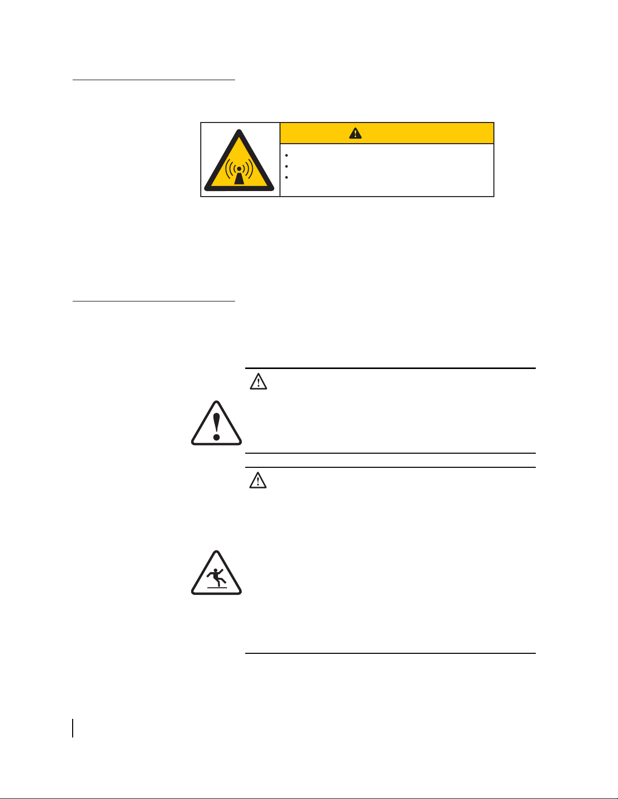
Product warning labels
The following safety alert label is affixed to each side of the
satellite antenna feed arm:
CAUTION
This device emits radio frequency energy
Keep two feet (0.6 meters) away from this point
Before servicing or upgrading, unplug indoor
power connection
T0145005
This label advises that the antenna emits radio frequency (RF)
energy. Because of this potential safety hazard, observe all
cautions in the following section (
concerning RF radiation.
Antenna installation safety)
Antenna installation safety
Observe the following precautions when installing the satellite
antenna. This manual also includes additional safety alerts where
appropriate concerning specific installation
procedures.
WARNING
Only HNS-certified installers may install or service
DIRECWAY earth stations and components. All
HNS-certified installers must expressly acknowledge the
HNS requirements for DIRECWAY installations.
DANGER
If you work on a roof, tower, or other high structure or use a
ladder or scaffold to access the work site, follow these
precautions to prevent personal injury or death:
• Walk only on sound roof structures.
• Make sure the antenna assembly and installation
surface are structurally sound so they can support all
loads (equipment weight, ice, and wind).
• Use appropriate safety equipment (for example, a
lifeline), depending on the work location.
• Follow all safety precautions from the manufacturers of
all safety equipment and other equipment used.
• Perform as many procedures as possible on the ground.
• Important safety information
iv
1035567-0001 Revision A
Page 5
DANGER
• To avoid electric shock, stay at least 20 ft from power
lines.
• If any part of the antenna or mount assembly comes in
contact with a power line, call your local power
company to remove it. Do not try to remove it yourself.
Failure to heed these warnings could result in serious injury
or death.
WARNING
• Do not work in high wind or rain or if a storm, lightning,
or other adverse weather conditions are present or
approaching.
• Do not attempt to assemble, move, or mount the
antenna on a windy day. Even a slight wind can create
strong, unexpected forces on the antenna surface.
• Important safety information
1035567-0001 Revision A
v
Page 6
CAUTION
Observe these precautions to avoid exposure to RF
radiation, a potential safety hazard:
• The antenna must be installed in a location or manner
not readily accessible to children and in a manner that
prevents human exposure to potentially harmful levels
of radiation.
• Antennas mounted in Puerto Rico, the continental
United States, or at any site with greater than a 30°
elevation angle must be installed such that the lower lip
of the antenna reflector is at least 5 ft above any surface
upon which a person might be expected to stand, and
3
ft 3 in. from any opening (such as a door or window) in
a building or adjacent structure.
• Antennas mounted in Canada, Alaska, Hawaii, or any
site with less than a 30° elevation must be installed such
that the lower lip of the antenna reflector is at least
5
ft 9 in. above any surface upon which a person might
be expected to stand, and 3 ft 3 in. from any opening
(such as a door or window) in a building or adjacent
structure.
• The antenna must be mounted such that no object
which could reasonably be expected to support a
person is within 6 ft 7 in. of the edges of a cylindrical
space extending from the antenna reflector.
• If the above distance requirements cannot be met, the
antenna must be mounted in a controlled area
inaccessible to the general public, such as a fenced
enclosure or a roof.
• The antenna must be mounted such that there is no
object outside the controlled area which could
reasonably be expected to support a person within
6
ft 7 in. of the edges of a cylindrical space extending
from the antenna reflector.
• A fenced installation must have a locked entry, and the
fenced area must be large enough to protect the general
public from exposure to potentially harmful levels of
radiation.
• Important safety information
vi
1035567-0001 Revision A
Failure to observe these cautions could result in injury to
eyes or other personal injury.
Page 7
CAUTION
• All installations of any type or size must carry an
industry standard and government approved Radiation
Hazard Caution label on the feed arm.
• A fenced or roof installation in a commercial, industrial,
or institutional environment must carry a Radiation
Hazard Caution sign on the access door, gate, or
permanently mounted access ladder that is within plain
sight of anyone approaching the antenna from the front
or sides of the reflector.
Failure to observe these cautions could result in injury to
eyes or other personal injury.
Some installations may require additional precautions. See also
the Antenna Site Preparation and Mount Installation Guide
(HNS 1035678-0001).
• Important safety information
1035567-0001 Revision A
vii
Page 8

viii
• Important safety information
1035567-0001 Revision A
Page 9

Contents
Important safety information . . . . . . . . . . . . . . . . . . . . . iii
Types of warnings used in this manual . . . . . . . . . . . . . . . . . . . iii
Product warning labels . . . . . . . . . . . . . . . . . . . . . . . . . . . . . . . . iv
Antenna installation safety . . . . . . . . . . . . . . . . . . . . . . . . . . . . . iv
About this document . . . . . . . . . . . . . . . . . . . . . . . . . . . .xv
Scope and audience . . . . . . . . . . . . . . . . . . . . . . . . . . . . . . . . . .xv
Organization . . . . . . . . . . . . . . . . . . . . . . . . . . . . . . . . . . . . . . . .xv
Revision record. . . . . . . . . . . . . . . . . . . . . . . . . . . . . . . . . . . . . xvi
Chapter 1
Overview . . . . . . . . . . . . . . . . . . . . . . . . . . . . . . . . . . . . . . .1
Broadband satellite system components. . . . . . . . . . . . . . . . . . . .1
Antenna installation overview . . . . . . . . . . . . . . . . . . . . . . . . . . .3
Tasks related to antenna installation . . . . . . . . . . . . . . . . . . . . . .4
Selecting the installation site . . . . . . . . . . . . . . . . . . . . . . . . . .4
Installing the antenna mount . . . . . . . . . . . . . . . . . . . . . . . . . .4
Grounding. . . . . . . . . . . . . . . . . . . . . . . . . . . . . . . . . . . . . . . . .4
Cables and cabling . . . . . . . . . . . . . . . . . . . . . . . . . . . . . . . . . .4
Chapter 2
Antenna parts and required tools. . . . . . . . . . . . . . . . . . .5
Antenna kit components. . . . . . . . . . . . . . . . . . . . . . . . . . . . . . . .5
Az/El cap and collar . . . . . . . . . . . . . . . . . . . . . . . . . . . . . . . . .6
Antenna reflector . . . . . . . . . . . . . . . . . . . . . . . . . . . . . . . . . . .6
Feed arm and radio . . . . . . . . . . . . . . . . . . . . . . . . . . . . . . . . . .7
Trimast (or other antenna mount). . . . . . . . . . . . . . . . . . . . . . .8
Optional shroud . . . . . . . . . . . . . . . . . . . . . . . . . . . . . . . . . . . .8
Small hardware list. . . . . . . . . . . . . . . . . . . . . . . . . . . . . . . . . . . .9
Tools. . . . . . . . . . . . . . . . . . . . . . . . . . . . . . . . . . . . . . . . . . . . . .10
Chapter 3
Installing the radio and antenna assemblies . . . . . . . . .11
Determining the pointing values . . . . . . . . . . . . . . . . . . . . . . . .12
Assembling the Az/El cap . . . . . . . . . . . . . . . . . . . . . . . . . . . . .13
Installing the Az/El cap onto the antenna. . . . . . . . . . . . . . . . . .15
Adjusting elevation. . . . . . . . . . . . . . . . . . . . . . . . . . . . . . . . .16
Adjusting polarization . . . . . . . . . . . . . . . . . . . . . . . . . . . . . .18
Installing the fine elevation pointing tool. . . . . . . . . . . . . . . . . .20
• Contents
1035567-0001 Revision A
ix
Page 10

Installing a shim for vertical transmit polarization . . . . . . . . . .21
Installing the radio assembly on the feed arm . . . . . . . . . . . . . .25
Connecting the feed arm to the antenna reflector. . . . . . . . . . . .26
Installing the antenna assembly onto the mast . . . . . . . . . . . . . .28
Attaching the optional shroud . . . . . . . . . . . . . . . . . . . . . . . . . .29
Chapter 4
Cabling and connections . . . . . . . . . . . . . . . . . . . . . . . . .31
Routing the cables at the ODU. . . . . . . . . . . . . . . . . . . . . . . . . .32
Connecting the transmit and receive cables . . . . . . . . . . . . . . . .33
Transmit cable . . . . . . . . . . . . . . . . . . . . . . . . . . . . . . . . . . . .33
Receive cable . . . . . . . . . . . . . . . . . . . . . . . . . . . . . . . . . . . . .34
Ground connection . . . . . . . . . . . . . . . . . . . . . . . . . . . . . . . . . . .35
Chapter 5
Pointing the antenna . . . . . . . . . . . . . . . . . . . . . . . . . . . .37
Antenna pointing overview . . . . . . . . . . . . . . . . . . . . . . . . . . . .38
Using the installation software . . . . . . . . . . . . . . . . . . . . . . . .38
Peaking the signal. . . . . . . . . . . . . . . . . . . . . . . . . . . . . . . . . .38
Personnel requirements . . . . . . . . . . . . . . . . . . . . . . . . . . . . .39
Pointing parameters . . . . . . . . . . . . . . . . . . . . . . . . . . . . . . . .39
Outdoor pointing interface . . . . . . . . . . . . . . . . . . . . . . . . . . .39
OPI block . . . . . . . . . . . . . . . . . . . . . . . . . . . . . . . . . . . . . .40
Prerequisites for antenna pointing . . . . . . . . . . . . . . . . . . . . . . .41
Adjusting the antenna. . . . . . . . . . . . . . . . . . . . . . . . . . . . . . . . .42
Pointing adjustments on Az/El cap. . . . . . . . . . . . . . . . . . . . .43
Checking the azimuth, elevation, and polarization settings . . . .44
Receive pointing. . . . . . . . . . . . . . . . . . . . . . . . . . . . . . . . . . . . .45
Adjusting azimuth . . . . . . . . . . . . . . . . . . . . . . . . . . . . . . .45
Peaking the signal. . . . . . . . . . . . . . . . . . . . . . . . . . . . . . . . . .46
Adjusting elevation. . . . . . . . . . . . . . . . . . . . . . . . . . . . . . .47
Adjusting polarization . . . . . . . . . . . . . . . . . . . . . . . . . . . .49
Isolating the transmit signal . . . . . . . . . . . . . . . . . . . . . . . . . . . .50
Final steps. . . . . . . . . . . . . . . . . . . . . . . . . . . . . . . . . . . . . . . . . .52
Removing the fine elevation pointing tool . . . . . . . . . . . . . . .52
• Contents
x
1035567-0001 Revision A
Acronyms and abbreviations . . . . . . . . . . . . . . . . . . . . .53
Index . . . . . . . . . . . . . . . . . . . . . . . . . . . . . . . . . . . . . . . . .55
Page 11

Figures
Chapter 1
1. Installed .74 m antenna. . . . . . . . . . . . . . . . . . . . . . . . . . . . . . . . . . . . . . . . . . . . .2
Chapter 2
2. Az/el cap . . . . . . . . . . . . . . . . . . . . . . . . . . . . . . . . . . . . . . . . . . . . . . . . . . . . . . . .6
3. Antenna reflector (rear view) . . . . . . . . . . . . . . . . . . . . . . . . . . . . . . . . . . . . . . . .6
4. Feed arm (unattached) . . . . . . . . . . . . . . . . . . . . . . . . . . . . . . . . . . . . . . . . . . . . .7
5. Radio assembly. . . . . . . . . . . . . . . . . . . . . . . . . . . . . . . . . . . . . . . . . . . . . . . . . . .7
6. Trimast in various configurations. . . . . . . . . . . . . . . . . . . . . . . . . . . . . . . . . . . . .8
7. Optional shroud for feed assembly. . . . . . . . . . . . . . . . . . . . . . . . . . . . . . . . . . . .8
Chapter 3
8. Revolving plate. . . . . . . . . . . . . . . . . . . . . . . . . . . . . . . . . . . . . . . . . . . . . . . . . .13
9. Aligning the revolving plate. . . . . . . . . . . . . . . . . . . . . . . . . . . . . . . . . . . . . . . .13
10. Aligning the Az/el cap bolts . . . . . . . . . . . . . . . . . . . . . . . . . . . . . . . . . . . . . . . .14
11. Antenna adjustments for elevation and polarization . . . . . . . . . . . . . . . . . . . . .15
12. Locating the polarization scale . . . . . . . . . . . . . . . . . . . . . . . . . . . . . . . . . . . . . .15
13. Adjusting elevation. . . . . . . . . . . . . . . . . . . . . . . . . . . . . . . . . . . . . . . . . . . . . . .16
14. Locating the elevation reference edge . . . . . . . . . . . . . . . . . . . . . . . . . . . . . . . .17
15. Reading the elevation reference edge. . . . . . . . . . . . . . . . . . . . . . . . . . . . . . . . .17
16. Adjusting polarization . . . . . . . . . . . . . . . . . . . . . . . . . . . . . . . . . . . . . . . . . . . .18
17. Placing the Az/El cap on the antenna reflector. . . . . . . . . . . . . . . . . . . . . . . . . .19
18. The fine elevation pointing tool . . . . . . . . . . . . . . . . . . . . . . . . . . . . . . . . . . . . .20
19. Shim location next to TRIA . . . . . . . . . . . . . . . . . . . . . . . . . . . . . . . . . . . . . . . .21
20. Horizontal shim and vertical shim for transmit polarization . . . . . . . . . . . . . . .22
21. Direction of TRIA rotation for vertical polarization . . . . . . . . . . . . . . . . . . . . .23
22. TRIA position for horizontal and vertical transmit polarization . . . . . . . . . . . .24
23. Securing the O-ring . . . . . . . . . . . . . . . . . . . . . . . . . . . . . . . . . . . . . . . . . . . . . .25
24. Radio assembly installed on the feed arm . . . . . . . . . . . . . . . . . . . . . . . . . . . . .26
25. Inserting the wedge nut bolt . . . . . . . . . . . . . . . . . . . . . . . . . . . . . . . . . . . . . . . .27
26. Installing the antenna assembly onto the mast . . . . . . . . . . . . . . . . . . . . . . . . . .28
27. Feed horn groove . . . . . . . . . . . . . . . . . . . . . . . . . . . . . . . . . . . . . . . . . . . . . . . .29
28. Shroud screws. . . . . . . . . . . . . . . . . . . . . . . . . . . . . . . . . . . . . . . . . . . . . . . . . . .30
29. Feed assembly with shroud. . . . . . . . . . . . . . . . . . . . . . . . . . . . . . . . . . . . . . . . .30
• Figures
1035567-0001 Revision A
xi
Page 12

Chapter 4
30. Transmit and receive cable configurations. . . . . . . . . . . . . . . . . . . . . . . . . . . . .32
31. Connecting the transmit cable . . . . . . . . . . . . . . . . . . . . . . . . . . . . . . . . . . . . . .33
32. Connecting the receive cable to the LNB. . . . . . . . . . . . . . . . . . . . . . . . . . . . . .34
33. Ground screw on the transmitter . . . . . . . . . . . . . . . . . . . . . . . . . . . . . . . . . . . .35
Chapter 5
34. OPI (optional tool) . . . . . . . . . . . . . . . . . . . . . . . . . . . . . . . . . . . . . . . . . . . . . . .39
35. OPI . . . . . . . . . . . . . . . . . . . . . . . . . . . . . . . . . . . . . . . . . . . . . . . . . . . . . . . . . . .40
36. OPI block . . . . . . . . . . . . . . . . . . . . . . . . . . . . . . . . . . . . . . . . . . . . . . . . . . . . . .40
37. Adjusting azimuth, elevation, and polarization . . . . . . . . . . . . . . . . . . . . . . . . .42
38. Pointing features on the Az/el cap . . . . . . . . . . . . . . . . . . . . . . . . . . . . . . . . . . .43
39. Antenna adjustment locations. . . . . . . . . . . . . . . . . . . . . . . . . . . . . . . . . . . . . . .43
40. Locating and lining up the azimuth bearing . . . . . . . . . . . . . . . . . . . . . . . . . . . .44
41. Adjusting azimuth. . . . . . . . . . . . . . . . . . . . . . . . . . . . . . . . . . . . . . . . . . . . . . . .45
42. Adjusting elevation. . . . . . . . . . . . . . . . . . . . . . . . . . . . . . . . . . . . . . . . . . . . . . .47
43. Elevation nuts . . . . . . . . . . . . . . . . . . . . . . . . . . . . . . . . . . . . . . . . . . . . . . . . . . .47
44. Adjusting elevation. . . . . . . . . . . . . . . . . . . . . . . . . . . . . . . . . . . . . . . . . . . . . . .49
xii
• Figures
1035567-0001 Revision A
Page 13

Tables
Chapter 2
1. Parts list . . . . . . . . . . . . . . . . . . . . . . . . . . . . . . . . . . . . . . . . . . . . . . . . . . . . . . . .9
2. Tools required to install and point the antenna. . . . . . . . . . . . . . . . . . . . . . . . . .10
• Tables
1035567-0001 Revision A
xiii
Page 14

xiv
• Tables
1035567-0001 Revision A
Page 15

About this document
Scope and audience
Organization
This manual explains how to assemble, install, and point the
DIRECWAY
for qualified installers who are familiar with satellite antenna
installation practices and are capable of properly applying the
information presented. The installer may be required to:
• Use a power drill to drill holes into a building.
• Locate studs, rafters, or trusses and drill holes in the exact
center of them.
• Determine whether there are water pipes, electrical wiring, or
gas lines hidden in the walls near where you will be drilling.
• Route coaxial cable through the foundation wall, under
floors, and through interior walls.
• Ground the satellite antenna and coaxial cable as
recommended in the National Electrical Code (published by
the National Fire Protection Association, Batterymarch Park,
Quincy, MA 02269).
This manual is divided into the following chapters:
• Chapter 1 – Overview includes a summary of the installation
steps and tells you where to find information about tasks
related to antenna installation.
• Chapter 2 – Antenna parts and required tools describes the
components and parts provided in the antenna kit.
• Chapter 3 – Installing the radio and antenna assemblies
provides instructions for installing the antenna.
• Chapter 4 – Cabling and connections provides information
about making connections to the radio assembly.
• Chapter 5 – Pointing the antenna explains how to point the
antenna at the satellite, connect the transmitter, and acquire
the satellite signal.
®
model AN4-076-DF .74 m antenna. It is written
• About this document
1035567-0001 Revision A
xv
Page 16

Revision record
This section describes the revision history of this manual.
Revision Date of issue Scope
1 April 7, 2004 Initial release
A October 31, 2005 Production release
xvi
• About this document
1035567-0001 Revision A
Page 17

Chapter 1
Overview
The DIRECWAY model AN4-074-DF .74 m antenna is used for
Ku-band consumer installations.
This chapter presents an overview of the DIRECWAY broadband
satellite system, a summary of the antenna installation steps, and
information about tasks related to antenna installation. These
topics are included in the following sections:
• Broadband satellite system components on page 1
• Antenna installation overview on page 3
• Tasks related to antenna installation on page 4
Broadband satellite system components
The .74 m antenna is a part of the DIRECWAY broadband
satellite system, which consists of the following major
components:
• Indoor unit (IDU)
• Antenna and radio assembly (outdoor unit, ODU)
• Cables for connecting the IDU to the antenna (radio) and the
computer
• Installation software, including antenna pointing functions
Chapter 1 • Overview
1035567-0001 Revision A
1
Page 18
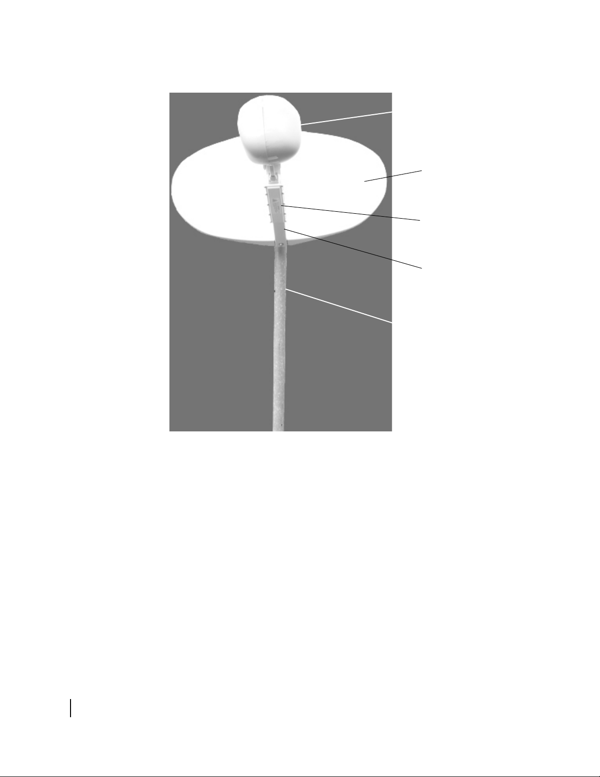
Figure 1 shows the .74 m antenna installed on a pole mount.
Radio (not visible)
in optional shroud
Antenna
reflector
Transmitter
Feed arm
Mast
Chapter 1 • Overview
2
1035567-0001 Revision A
Figure 1: Installed .74 m antenna
Page 19

Antenna installation overview
The antenna installation steps and related tasks are summarized
below. The steps in bold type are documented in this manual.
1. Choose an installation site.
2. Select a method for mounting the antenna.
3. Install the antenna mount.
4. Install the IDU.
Note: Install the IDU before installing the antenna so you
can run the installation software to determine the pointing
values (azimuth, elevation, and polarization).
5. Use the installation software to determine the pointing
values (azimuth, elevation, and polarization).
(Chapter 3 – Installing the radio and antenna assemblies)
6. Assemble and install the Az/El cap.
(Chapter 3 – Installing the radio and antenna assemblies)
7. Install the radio on the feed arm.
(Chapter 3 – Installing the radio and antenna assemblies)
8. Attach the feed arm to the antenna reflector.
(Chapter 3 – Installing the radio and antenna assemblies)
9. Assemble the antenna.
(Chapter 3 – Installing the radio and antenna assemblies)
10. Install the antenna on the mount.
(Chapter 3 – Installing the radio and antenna assemblies)
11. Run cable to connect the radio to the IDU.
12. Connect the cables to the ODU.
(Chapter 4 – Cabling and connections)
13. Ground the antenna assembly.
14. Point the antenna.
(Chapter 5 – Pointing the antenna)
For the steps not shown in bold type, see the following section,
Tasks related to antenna installation.
Chapter 1 • Overview
1035567-0001 Revision A
3
Page 20

Tasks related to antenna installation
This section explains where you can find information on tasks
related to antenna installation.
Selecting the installation
site
Installing the antenna
mount
Grounding
Cables and cabling
Factors you should consider in selecting an installation site are
discussed in the DIRECWAY Antenna Site Preparation and
Mount Installation Guide (HNS
A suitable antenna mount must be installed before the antenna
can be installed. For pole mounts that require a concrete base, you
must allow at least 24 hr for the concrete to cure before you can
install the antenna. Plan accordingly.
For complete information concerning antenna mount installation,
including various mounting methods, refer to the DIRECWAY
Antenna Site Preparation and Mount Installation Guide. Use
only the antenna mount installation methods documented in the
DIRECWAY Antenna Site Preparation and Mount Installation
Guide.
The entire antenna assembly must be grounded. For grounding
information, refer to your training, best grounding practices, and
applicable parts of the National Electrical Code (NEC).
For cable specifications, see the IDU manual. How the cable is
run depends on the specific installation site. Route and connect
the cable according to your training and best practices.
1035678-0001).
Chapter 1 • Overview
4
1035567-0001 Revision A
Page 21

Chapter 2
Antenna parts and required tools
This chapter describes the components and parts provided with
the model AN4-074-DF antenna kit. It includes the following
sections:
• Antenna kit components on page 5
• Small hardware list on page 9
• Too ls on page 10
Antenna kit components
This section identifies and describes the key components of the
m antenna kit. For an illustration of an installed .74 m
.74
antenna, see
The key components are:
• Azimuth/elevation (Az/El) cap
• Antenna reflector
• Feed arm and radio assembly
Related components:
• Trimast or other mount
• Optional shroud
Figure 1 on page 2.
Chapter 2 • Antenna parts and required tools
1035567-0001 Revision A
5
Page 22
Az/El cap and collar
The Az/El cap (Figure 2) is used to point the antenna at the
satellite. The Az/El cap is shipped unassembled; it can be
assembled in about 2 to 5 min.
Figure 2: Az/el cap
Az/El mechanism
Revolving plate
Polarization plate
The Az/El cap is shipped in a bag containing:
• Az/El mechanism
• Revolving plate
• Polarization plate
• Four 7/16-in. bolts, nuts, and washers
Antenna reflector
Chapter 2 • Antenna parts and required tools
6
1035567-0001 Revision A
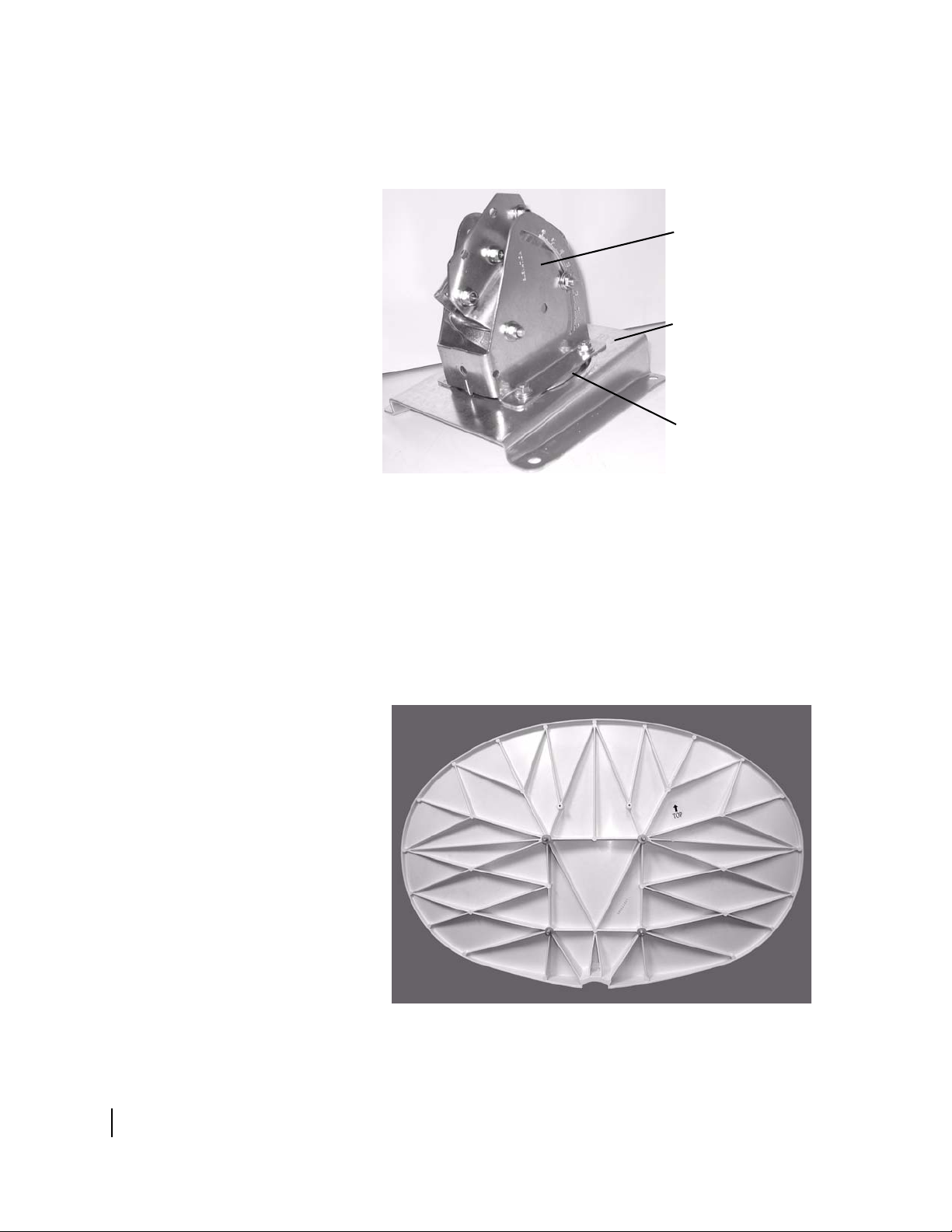
The antenna reflector is shown in Figure 3.
Figure 3: Antenna reflector (rear view)
Page 23

Feed arm and radio
Figure 4 shows the feed arm, and Figure 5 shows the radio
assembly.
Figure 4: Feed arm (unattached)
The radio assembly (Figure 5) consists of the transmitter, low
noise block converter (LNB), and transmit/receive isolation
assembly (TRIA).
Figure 5: Radio assembly
Chapter 2 • Antenna parts and required tools
1035567-0001 Revision A
7
Page 24

Trimast (or other antenna
mount)
The trimast is not part of the antenna kit. It is shown here because
it is the most commonly used mounting option for the .74
antenna. As shown in
Figure 6, the trimast can be configured and
m
manipulated in several ways to adapt it for mounting onto
surfaces of various angles. For other suitable mounting options,
see the DIRECWAY Antenna Site Preparation and Mount
Installation Guide (HNS
1035678-0001).
Wall
T0145002
Figure 6: Trimast in various configurations
Optional shroud
Mast
Struts (2)
Flat roof
Pitched roof
The shroud shown in Figure 4 is optional. It attaches to the feed
assembly to protect the feed assembly and improve its
appearance, but it is not required.
Chapter 2 • Antenna parts and required tools
8
1035567-0001 Revision A
Figure 7: Optional shroud for feed assembly
Page 25

Small hardware list
Item Details Quantity
Bolts 5/16-18 2
Flat washers 5/16 in. 6
Lock washers 5/16 in. 2
Lock washers M4 4
Bolts (with Az/El cap) 7/16 in. 4
Nuts (with Az/El cap) 7/16 in. 4
Washers (with Az/El cap) 7/16 in. 4
Allen screws M4 4
Self-tapping screws 5/16 in. 4
Wedge nut 5/16-18 1
Hex-head bolt for wedge nut 5/16-18 x 2 in. 1
O-ring Rubber 1
Grounding bolt 1/4-20 x 1/2 in. 1
Star washer Toothed, 1/4 in. 1
Hex-head ground nut 1/4-20 1
Tabl e 1 lists the small hardware parts that are included in the
antenna kit. You may have hardware left over after you have
completed installation.
Table 1: Parts list
Parts used for antenna assembly and installation
Parts used for grounding
Note: Items needed to connect the antenna to the IDU are
shipped with the IDU.
If you use the optional shroud, three Phillips head screws are
included in a bag taped to the shroud.
Chapter 2 • Antenna parts and required tools
1035567-0001 Revision A
9
Page 26

Tools
Tabl e 2 lists the tools required to assemble, install, and point the
antenna.
Ta b le 2 : Tools required to install and point the antenna
Tool Details
Open-end wrench 1/2 in.
Open-end or
socket wrench
Socket wrench or
adjustable wrench
Socket wrench 1/2 in.
Torque wrench With 1/2-in. socket capable of torquing to
Allen wrench 3 mm
Phillips-head screwdriver No. 2; needed if the optional shroud is
Compass Hand-held
Pencil Carpenter’s pencil
Fine elevation pointing
tool
7/16 in.
5/16 in.
12 ft-lbf
installed
Reusable
10
Chapter 2 • Antenna parts and required tools
1035567-0001 Revision A
Page 27

Chapter 3
Installing the radio and
antenna assemblies
This chapter explains how to install the antenna, radio, and
associated hardware. Topics include:
• Determining the pointing values on page 12
• Assembling the Az/El cap on page 13
• Installing the Az/El cap onto the antenna on page 15
• Installing the fine elevation pointing tool on page 20
• Connecting the feed arm to the antenna reflector on page 26
• Installing a shim for vertical transmit polarization on
page 21
• Installing the radio assembly on the feed arm on page 25
• Connecting the feed arm to the antenna reflector on page 26
• Installing the antenna assembly onto the mast on page 28
• Attaching the optional shroud on page 29
The mast must be installed before you can install the antenna. For
information on antenna mounting methods, see the DIRECWAY
Antenna Site Preparation and Mount Installation Guide
(HNS
1035678-0001).
CAUTION
Before you install the antenna, read all safety information in
the section titled
Important safety information on page iii.
Chapter 3 • Installing the radio and antenna assemblies
1035567-0001 Revision A
11
Page 28

Determining the pointing values
Before proceeding, use the installation software to determine the
initial values to use for setting azimuth, elevation, and
polarization. Record these values and keep them handy for
reference as you install and point the antenna. In this manual,
installation software refers to:
• Satellite-based commissioning (SBC) – This is the preferred
and most automated method for pointing the antenna. You
connect to a Web-based auto-commissioning system
(WebACS) and follow the on-screen instructions.
or
• WebSetup – You log onto a DIRECWAY Web site and use the
WebSetup installation software.
You may use installation software from either of these sources. In
each case, the software configures the IDU, calculates your exact
location, and uses the location and other information to help you
point the antenna. The installation software calculates the values
you use to set azimuth, elevation, and polarization.
Follow the instructions in the IDU installation manual for
accessing and using SBC or WebSetup.
12
Chapter 3 • Installing the radio and antenna assemblies
1035567-0001 Revision A
Page 29

Assembling the Az/El cap
The Az/El cap is shipped un-assembled. Follow the directions in
this section to assemble it. You should be able to assemble it in
about 2-5 min.
To assemble the Az/El cap:
1. Place the revolving plate on a flat surface. See Figure 8.
Figure 8: Revolving plate
2. Place the polarization plate over the revolving plate.
3. Use one hand to hold the two plates together. Align the
revolving plate so its four bolt holes are visible, as shown in
Figure 9.
Figure 9: Aligning the revolving plate
Chapter 3 • Installing the radio and antenna assemblies
1035567-0001 Revision A
13
Page 30

4. Place the Az/El mechanism over the revolving plate so the
bolt holes align.
5. Install a bolt from underneath the revolving plate. While
holding it with one hand, install the 7/16-in. flat washer and
nut. See
Figure 10.
6. Repeat until all four bolts are installed.
Align bolt from
underneath and
install washer
and nut.
Figure 10: Aligning the Az/el cap bolts
14
Chapter 3 • Installing the radio and antenna assemblies
1035567-0001 Revision A
Page 31

Installing the Az/El cap onto the antenna
Before you attach the Az/El cap to the antenna, you must set the
antenna elevation and polarization. As you set the elevation and
polarization, refer to
Figure 11.
Clamp bolts
(3)
Canister
Figure 11: Antenna adjustments for elevation and polarization
Elevation nuts
(one on each side)
Elevation
scale
TOP label
Polarization
scale
Polarization nuts (4)
The cap has an arrow, labeled TOP, to show you how to orient the
cap vertically. (See
Figure 12.)
Figure 12: Locating the polarization scale
Chapter 3 • Installing the radio and antenna assemblies
1035567-0001 Revision A
15
Page 32

Adjusting elevation
This section describes how to adjust the antenna elevation to the
value determined by the installation software. Later, when you
point the antenna, you fine-tune the elevation adjustment.
Figure 13 illustrates how you adjust the elevation by moving the
antenna up and down.
Elevation
Elevation
T0145007
Figure 13: Adjusting elevation
To adjust the elevation:
1. Make sure you know the elevation value calculated by the
installation software.
2. Orient the Az/El cap so the TOP label is at the upper right.
16
Chapter 3 • Installing the radio and antenna assemblies
1035567-0001 Revision A
Page 33

3. Use a 1/2-in. socket wrench or open-end wrench to loosen the
two elevation nuts. See
Figure 14.
4. Locate the elevation reference edge on the elevation scale on
the right side of the cap assembly. See Figures
Figure 14: Locating the elevation reference edge
14 and 15.
Elevation nut
(one on each
side)
Elevation
reference
edge
Read the elevation value
at the elevation reference
edge. In this picture, the
elevation is set to 34°.
Figure 15: Reading the elevation reference edge
5. Move the canister until the elevation reference edge is at the
correct value.
Later, when you point the antenna, you fine-tune the elevation
adjustment.
6. When the edge is at the correct elevation value, tighten the
two elevation nuts.
Chapter 3 • Installing the radio and antenna assemblies
1035567-0001 Revision A
17
Page 34

Adjusting polarization
This section describes how to adjust the antenna’s polarization to
the value determined by the installation software. Later, when you
point the antenna, you fine-tune the polarization adjustment.
Figure 16 illustrates how you adjust polarization by rotating the
antenna.
Polarization
T0145008
Figure 16: Adjusting polarization
Adjust polarization as follows:
1. Make sure you know the polarization value calculated by the
installation software.
2. Locate the polarization scale (see Figure 12 on page 15). The
0 value is at the top of the Az/El cap.
3. Turn the Az/El cap to the correct polarization value. Align the
mark on the top of the Az/El cap with the correct value on the
polarization scale.
Figure 12 on page 15 shows a setting of
positive 3 °. Each tick mark represents 2 °.
4. When the polarization is at the correct value, tighten the four
polarization nuts. As you tighten, make sure the polarization
remains at the correct value.
Later, when you point the antenna, you fine-tune the
polarization adjustment.
18
Chapter 3 • Installing the radio and antenna assemblies
1035567-0001 Revision A
Page 35

5. Place the Az/El cap over the screw holes in the back of the
antenna reflector (
see Figure 17).
Self-tapping screws
Self-tapping screws
Bottom of reflector
Figure 17: Placing the Az/El cap on the antenna reflector
Make sure the Az/El cap mount screw holes are properly
aligned with the holes in the antenna reflector. The arrow on
the Az/El labeled TOP should point to the top of the antenna
reflector. Make sure the reflector is oriented so the section
with a hole in its rim is on the bottom.
6. Use a 7/16-in. socket or open-end wrench to install the four
5/16-in. self-tapping screws and flat washers in the holes.
Turn each screw clockwise until contact is made with the
mount surface. Then use a torque wrench with 1/2-in. socket
to tighten them to 10 ft-lbf. Do not overtighten.
Chapter 3 • Installing the radio and antenna assemblies
1035567-0001 Revision A
19
Page 36

Installing the fine elevation pointing tool
The fine elevation pointing tool (Figure 18) consists of a long
elevation adjustment bolt with a clamp on one end and a flange on
the other end. The clamp and flange attach to the Az/El cap as
shown in
Flange bolts
and nuts (2 sets)
Figure 18.
Flange
Elevation adjustment
nuts (2). Do not remove.
Elevation
adjustment
bolt
Do not remove
this nut and bolt.
Clamp
Clamp bolt with nut
on opposite end
Figure 18: The fine elevation pointing tool
Install the fine elevation pointing tool as follows:
1. Align the two clamp bolt holes with the holes at the base of
the elevation cap.
2. Use a 1/2-in. wrench to install the elevation clamp bolt and
nut.
3. Swing the flange so the two bolts on its wide side align with
the installation holes on the Az/El cap.
4. Insert the flange bolts in the holes and use a 1/2-in. wrench to
secure them using the flange bolt nuts.
20
Chapter 3 • Installing the radio and antenna assemblies
1035567-0001 Revision A
Page 37

Installing a shim for vertical transmit polarization
Follow the instructions in this section only if installation
specifications or a service order states that vertical transmit
polarization is required.
If vertical transmit polarization is not required, go to Installing
the radio assembly on the feed arm on page 25.
The radio assembly is shipped with a horizontal transmit
polarization shim installed. If vertical transmit polarization is
required, you must remove the horizontal shim and replace it with
a vertical transmit polarization shim.
Note: If you need to change from horizontal to vertical transmit
polarization on an antenna that has the radio assembly already
installed on the feed arm, you will have to remove the radio
assembly from the feed arm before you can follow the instructions
in this section.
Figure 19 shows where the shim is located and shows three of the
four Allen screws that hold the shim in place.
TRIA
Shim
(See also
Figure 20.)
Allen screws
(4 total)
Figure 19: Shim location next to TRIA
Waveguide
To replace the horizontal shim with a vertical shim, follow these
steps:
1. Obtain a vertical transmit polarization shim kit (HNS model
VTX-SHIM-KIT, P/N 1033809-0001).
Figure 20 on page 22 shows what a vertical shim looks like.
2. Loosen and remove the four Allen screws that hold the shim
in place. See
Figure 19.
3. Separate the end of the waveguide from the shim.
Chapter 3 • Installing the radio and antenna assemblies
1035567-0001 Revision A
21
Page 38

TRIA
Figure 20 illustrates the difference between the horizontal
shim and vertical shim. Note the positions of the alignment
pins.
Horizontal shim in place
O-ring
Alignment
pins
Horizontal shim
Figure 20: Horizontal shim and vertical shim for transmit polarization
Vertical shim in place
(In this photograph, the TRIA
has not yet been rotated.)
Vertical shim
4. Remove the horizontal shim and O-ring.
5. Install the vertical shim and O-ring in the same location.
Because of its shape and alignment pins on the
transmit/receive isolation assembly (TRIA), the vertical shim
can only be installed in the position shown in
(upper right photo). Note the position of the alignment pins.
Likewise, the horizontal shim can only be installed in one
position.
Alignment
pins
Figure 20
22
Chapter 3 • Installing the radio and antenna assemblies
1035567-0001 Revision A
Page 39

Because of the shim’s alignment pins, you must rotate the
TRIA 90
° from its horizontal polarization position. You must
rotate the TRIA before you re-attach the waveguide end so
you can insert the shim alignment pins into the waveguide
end plate. See Figures
Figure 21: Direction of TRIA rotation for vertical polarization
21 and 22.
Chapter 3 • Installing the radio and antenna assemblies
1035567-0001 Revision A
23
Page 40

Figure 22 shows how the TRIA is positioned for horizontal
transmit polarization compared to how it is positioned for
vertical transmit polarization.
Horizontal polarization
TRIA
TRIA
TRIA rotated for vertical polarization
Figure 22: TRIA position for horizontal and vertical transmit
polarization
6. Make sure the O-ring shown in Figure 21 on page 23 is in
place in the shim.
7. With the TRIA correctly positioned (rotated), place the
waveguide end plate against the shim.
8. Insert and tighten the four Allen screws.
Now you are ready to install the radio assembly on the feed arm.
24
Chapter 3 • Installing the radio and antenna assemblies
1035567-0001 Revision A
Page 41

Installing the radio assembly on the feed arm
If the radio assembly is already attached to the feed arm, skip this
section and go to
reflector on page 26.
Follow these steps to install the radio assembly on the feed arm:
1. Place the O-ring in the circular depression in the square end
of the feed arm. See
Connecting the feed arm to the antenna
see Figure 23.
O-ring
Figure 23: Securing the O-ring
2. Align the square end of the radio assembly with the square
end of the feed arm so you can install the four M4 screws.
Install the lock washers on the screws. Use the Allen wrench
to install the M4 Allen screws, but do not fully tighten them.
3. Align the bolt holes on the top of the transmitter with the bolt
holes on the bottom of the feed arm.
4. Install the 5/16-18 bolts in the aligned holes. Finger tighten
them; do not tighten them further at this time.
5. Use the Allen wrench to tighten the Allen screws.
Chapter 3 • Installing the radio and antenna assemblies
1035567-0001 Revision A
25
Page 42

Feed assembly
6. Use a 5/16-in. socket wrench or open-end wrench to tighten
the bolts attaching the transmitter to the feed arm.
7. Make sure the transmitter and feed arm are oriented correctly,
as shown in
Figure 24.
Waveguide
Figure 24: Radio assembly installed on the feed arm
Connecting the feed arm to the antenna reflector
Transmitter
8. Attach the transmitter to the bottom of the feed arm.
When you are done, the assembly looks like Figure 24.
This section describes how to connect the feed arm to the antenna
reflector.
Note: If you are installing the antenna assembly on a metal pole
mount, it may be easier to attach the feed arm after you have
installed the antenna on the Az/El cap. See
assembly onto the mast on page 28. However, if you are using a
ladder, it may be easier to attach the feed arm to the antenna before
installing it on the Az/El cap.
Note: Make sure the feed arm is oriented as shown in Figure 24.
Installing the antenna
26
Chapter 3 • Installing the radio and antenna assemblies
1035567-0001 Revision A
Page 43

Transmitter
T0145009
To connect the feed arm to the antenna reflector:
1. Insert the 5/16-18 wedge nut, thinner end first, into the slot
provided on the back of the reflector, as shown in
The wedge nut is keyed so that it will fit properly only one
way into its slot in the reflector.
Make sure the hole in the wedge nut is aligned with the hole
in the reflector so you can insert the bolt. See
Antenna
reflector
5/16 - 18
wedge
nut
Feed arm
5/16-in.
flat washer
5/16 - 18
hex bolt
5/16-in.
lock washer
Figure 25.
Figure 25.
Wedge nut
Close-up view
Figure 25: Inserting the wedge nut bolt
2. Install the feed arm into the feed support socket on the
underside of the antenna reflector.
If you have the reflector turned upside down to insert the feed
arm, the orientation is the opposite of that shown in
Figure 25.
3. Use a 1/2-in. wrench to secure the feed arm with a 5/16-in.
flat washer, 5/16-in. lock washer, and 5/16-18 hex bolt. Use a
torque wrench to tighten the hex bolt from 8 ft-lbf to 10 ft-lbf.
Chapter 3 • Installing the radio and antenna assemblies
1035567-0001 Revision A
27
Page 44

Installing the antenna assembly onto the mast
To satellite
This section describes how to install the antenna assembly
(including the Az/El cap) onto the mast.
To install the antenna assembly onto the mast:
1. Lightly grease the area at the end of the mast or metal pole
that will be covered by the Az/El cap canister. This makes it
easy to rotate the antenna to adjust the azimuth. Any grease
will do; you can use automotive grease or household grease
such as Vaseline.
2. Use a 1/2-in. open-end wrench to loosen the three clamp nuts
and the elevation pivot bolt nut so the collar can slide over the
mast or metal pole.
3. Lift the antenna assembly and slide the Az/El cap onto the
mast or metal pole (
see Figure 26).
The antenna should face toward the satellite.
4. Tighten the clamp nuts all the way, then loosen them just
enough to move the antenna reflector from side to side and
adjust the azimuth. The clamp bolts should be as snug as
possible, but still allow the antenna reflector to be moved
from side to side.
28
Figure 26: Installing the antenna assembly onto the mast
Chapter 3 • Installing the radio and antenna assemblies
1035567-0001 Revision A
Clamp bolt nuts
Place Az/El cap
over mast or metal
pipe
Mast or metal pipe
Page 45

Attaching the optional shroud
This section explains how to attach the optional shroud to the feed
assembly. The shroud helps protect the feed assembly and
improves its appearance, but it is not required.
One side of the shroud is wider than the other. You place the
wider side on the right side of the feed assembly, as you face the
antenna.
The shroud screws are in a bag taped inside the shroud. The two
side screws are optional, but installing them does provide a
tighter fit and plug the screw holes.
Before placing the shroud over the feed assembly, be sure the
cables are positioned so that when the shroud is placed it does not
interfere with or cause sharp bends in the cables, especially at the
connectors.
To attach the shroud:
1. Facing the antenna reflector, place the shroud over the feed
assembly so that the broad side is on the right. Align the side
screw holes. The sides of the oval hole fit either behind, or in
the feed horn groove, which is shown in
Figure 27.
Groove
Figure 27: Feed horn groove
Chapter 3 • Installing the radio and antenna assemblies
1035567-0001 Revision A
29
Page 46

2. Use a No. 2 Phillips-head screwdriver to install the bottom
screw. See
Figure 28.
Side screw holes,
one on each side
Bottom
screw
Figure 28: Shroud screws
3. Optional: Install the two side screws. The final assembly will
look like
Figure 29.
30
Figure 29: Feed assembly with shroud
Chapter 3 • Installing the radio and antenna assemblies
1035567-0001 Revision A
Page 47

Chapter 4
Cabling and connections
This chapter illustrates where the ODU transmit, receive, and
ground connectors are located; shows how to route the transmit
and receive cables at the ODU, and explains how to connect the
transmit and receive cables to the radio assembly. You must
connect the transmit, receive, and ground cables before you can
point the antenna (
The chapter includes these sections:
• Routing the cables at the ODU on page 32
• Connecting the transmit and receive cables on page 33
• Ground connection on page 35
Before you perform the steps explained in this chapter, you must
route and terminate the transmit and receive cables from the IDU
to the ODU. For cable specifications and cabling between the
IDU and ODU, see the IDU instruction manual. How the cables
are run depends on the specific installation site. Route and
connect the cables according to your training and best practices.
Pointing the antenna on page 37).
CAUTION
Coaxial cable can corrode if exposed to moisture. Use
weatherproof connectors. Do not use push-on connectors.
Chapter 4 • Cabling and connections
1035567-0001 Revision A
31
Page 48

Routing the cables at the ODU
Route the coaxial transmit and receive cables at the ODU as
follows:
1. Route the transmit cable (marked with blue electrical tape) to
the back of the transmitter in a configuration similar to that
shown in
Figure 30.
Receive cable
(marked with
RED tape)
Figure 30: Transmit and receive cable configurations
Receive cable
Transmit cable
(marked with
BLUE tape)
passes through
feed arm.
Transmitter
T0145004
LNB
2. Route the receive cable (marked with red electrical tape) up
the mast, behind the reflector, and through the feed arm to the
LNB to achieve a configuration similar to that shown in
Figure 30.
32
Chapter 4 • Cabling and connections
1035567-0001 Revision A
Page 49

Connecting the transmit and receive cables
This section explains how to connect the transmit and receive
cables to the radio assembly.
Transmit cable
Connect the transmit cable to the transmitter as follows:
1. From inside the building, disconnect the IDU power supply.
2. Go outside and connect the transmit cable (marked with blue
electrical tape) to the transmitter connector marked IFL, as
shown in
Use a weatherproof connector.
Figure 31.
Transmitter cable
connector
Figure 31: Connecting the transmit cable
3. Tighten the connection with a 7/16-in. wrench.
4. Secure drip loops and other points on the cable with cable
ties.
5. Back inside the building, reconnect the IDU power supply.
Chapter 4 • Cabling and connections
1035567-0001 Revision A
33
Page 50

Receive cable
Connect the receive cable to the LNB as follows:
1. Connect the receive cable (marked with red tape) to the LNB
connector as illustrated in
Receive F connector, female
Figure 32.
Figure 32: Connecting the receive cable to the LNB
2. Tighten the cable connector with a 7/16-in. wrench.
3. Apply dielectric silicone grease to the connection.
4. Secure the cable with cable ties.
34
Chapter 4 • Cabling and connections
1035567-0001 Revision A
Page 51

Ground connection
Figure 33 shows the location of the ground screw on the
transmitter. Ground the transmitter and mast. For grounding
procedures, refer to your training, best grounding practices, and
applicable parts of the NEC.
Transmit
F connector,
female
Ground
screw
Not used
Figure 33: Ground screw on the transmitter
Chapter 4 • Cabling and connections
1035567-0001 Revision A
35
Page 52

36
Chapter 4 • Cabling and connections
1035567-0001 Revision A
Page 53

Chapter 5
Pointing the antenna
This chapter explains how to point the antenna and connect the
transmitter. Topics include:
• Antenna pointing overview on page 38
• Prerequisites for antenna pointing on page 41
• Adjusting the antenna on page 42
• Checking the azimuth, elevation, and polarization settings on
page 44
• Receive pointing on page 45
• Isolating the transmit signal on page 50
• Final steps on page 52
As you perform these procedures, observe the following safety
precautions:
• This device emits radio frequency energy when in
transmit mode. To avoid injury, do not place head or
other body parts between feed horn and antenna when
system is operational. Keep at least 2 ft away from the
area between the feed horn and the reflector when the
system is operational.
• Disconnect power from the IDU before performing
maintenance or adding upgrades to any antenna
components.
CAUTION
Chapter 5 • Pointing the antenna
1035567-0001 Revision A
37
Page 54

Antenna pointing overview
This chapter describes a general procedure for pointing the
antenna. The objectives for antenna pointing are to:
• Locate and detect the satellite signal
• Peak the signal to achieve the greatest possible signal
strength
Using the installation
software
Peaking the signal
The exact pointing procedure depends on the installation software
used, SBC or WebSetup. (For a description of SBC and
WebSetup, see
The installation software guides you through a step-by-step
process for installing the IDU and pointing the antenna. It
calculates your exact location and the values you use to set
polarization, elevation, and azimuth.
Use the information in this chapter as a guide for the overall
pointing process and for instructions on how to make mechanical
adjustments to the antenna. For specific steps, follow the
instructions in the IDU manual and on the installation software
screens.
In general you will alternate between these two activities:
• Following the software prompts and instructions
• Adjusting the antenna (azimuth, elevation, and polarization)
as necessary to acquire and then peak the satellite signal. The
required adjustments are different for each installation
location.
Correct antenna alignment is critical to the operation of the
system. When the antenna is pointed directly at the satellite, it
receives a strong signal. If it is not pointed properly, the signal
may be weak, and errors may result during data transfers.
Determining the pointing values on page 12.)
38
Chapter 5 • Pointing the antenna
1035567-0001 Revision A
Antenna pointing is accomplished by first receive pointing the
antenna and then isolating the transmit signal. Receive pointing
adjusts the antenna to obtain the best receive signal. Isolating the
transmit signal fine tunes the antenna alignment for the strongest
possible signal received by the DIRECWAY Network Operations
Center (NOC). Both processes are explained later in this chapter.
To point the antenna, you go through cycles of making small
adjustments to the antenna until you are satisfied you cannot get a
stronger satellite signal. When you have achieved the strongest
possible signal, you have peaked the signal.
You may achieve the strongest signal strength after just a few
adjustments, or you may find that several adjustments are needed.
Page 55

By obtaining the strongest possible signal you ensure that the
terminal can use all the system’s capacity.
Personnel requirements
Pointing parameters
Outdoor pointing interface
One person can point the antenna if an OPI is used. Otherwise,
pointing is usually a two-person task. One person aims and
adjusts the antenna while the other watches the signal strength
display on the computer and relays the readings to the person at
the antenna. A portable telephone or walkie-talkie is helpful for
this.
Prior to antenna pointing, you use the installation software to
enter parameters such as longitude, latitude, and polarization
angle. Or you can enter the local ZIP code and let the software
calculate these values.
The OPI, shown in Figure 34, is an optional tool that eliminates
the need for a laptop computer on the roof. It is a portable
repeater that displays the same values as are shown on the
computer running the installation software.
Cable
connector
Display
Figure 34: OPI (optional tool)
Chapter 5 • Pointing the antenna
1035567-0001 Revision A
39
Page 56

The OPI attaches to the receive cable from the LNB, as shown in
–
Figure 35. Note that the OPI will not work unless it is enabled on
the appropriate screen on the installation software. (Check the
box labeled
Enable OPI Display.) For further details, see Outdoor
Pointing Interface Operating Instructions
(HNS
1031832-0001).
LNB
DIRECWAY
22-kHz block
(if rquired)
OPI
IDU
Ground
block
T0145011
Figure 35: OPI
OPI block If you use an OPI with a model RA6-074 radio assembly, you
must use a 22-kHz block (filter). This block, illustrated in
Figure 36, is included in the OPI kit. Its model number is
OPI-Block 22 KHZ-BLOCK.
Female
connector –
to OPI
Male
connector
to cable
40
Chapter 5 • Pointing the antenna
1035567-0001 Revision A
Figure 36: OPI block
Install the block between the OPI and the radio as illustrated in
Figure 35. Some variations of this block may have female
F connectors at both ends. If the block you use has two F
connectors, you will have to make a jumper cable to connect to
the OPI.
Page 57

Prerequisites for antenna pointing
The following are required for antenna pointing:
• The antenna must be installed.
• The IDU must be installed.
• The transmit and receive cables must be connected to the
IDU and ODU.
• The outdoor pointing interface (OPI) must be installed.
• The ODU and IDU must be grounded.
• You must have access to the installation software. (See Using
the installation software on page 38.)
Chapter 5 • Pointing the antenna
1035567-0001 Revision A
41
Page 58

Adjusting the antenna
Negative (-)
LOS to satellite
To point the antenna you make three adjustments:
• Azimuth – Side-to-side adjustment
• Elevation – Adjustment up and down
• Polarization – Rotational adjustment
These adjustments are illustrated in Figure 37. The corresponding
mechanical adjustments on the antenna are explained in the
sections that follow.
A
z
i
m
u
t
-x°
h
0°
+
x
°
Positive (+)
Note: When recording
or using antenna pointing
values, you must pay
attention to whether
values are positive (+)
or negative (-).
Azimuth
T0145010
+
x
°
°
0
-x°
Elevation
Polarization
Polarization
Figure 37: Adjusting azimuth, elevation, and polarization
Elevation
-x°
Antenna reflector,
front view
0 °
+
x
°
42
Chapter 5 • Pointing the antenna
1035567-0001 Revision A
Page 59

Pointing adjustments on
Az/El cap
Figures 38 and 39 show the antenna parts that are used to adjust
antenna azimuth, elevation, and polarization.
Antenna reflector
Polarization scale
Holes for installing
fine elevation tool
Elevation scale
Figure 38: Pointing features on the Az/el cap
Polarization
nut (1 of 4)
Canister
Clamp bolt
(1 of 3)
Elevation nut
(one on each side)
Elevation scale
Figure 39: Antenna adjustment locations
Polarization
scale
TOP label
Chapter 5 • Pointing the antenna
1035567-0001 Revision A
43
Page 60

Checking the azimuth, elevation, and polarization settings
1. Check to see if the elevation reference and polarization
settings are still at their previously set values (the values
calculated by the installation software). If they are not, see
Installing the Az/El cap onto the antenna on page 15 and
follow the instructions to align the antenna to the correct
values.
2. If you have not already done so, tighten the clamp nuts all the
way; then loosen them just enough to move the antenna
reflector from side to side to adjust the azimuth.
The clamp bolts should be as snug as possible, while still
allowing the antenna reflector to be moved from side to side.
See Figure 39.
3. Use a compass to determine the azimuth bearing specified by
the installation software as follows:
a. Rotate the antenna reflector in azimuth (sideways) until the
reflector is pointed at the magnetic bearing. Use a pencil to
mark the location on the mast, and label this mark 1.
b. Mark the location on the Az/El cap above mark 1. This is
the azimuth alignment mark. (See
Figure 40.)
Elevation
reference
edge
Marks 1, 2, and 3
Azimuth
alignment mark
Figure 40: Locating and lining up the azimuth bearing
c. Make another mark on the mast 3/4-in. to the right of mark
1 and label it 2. Make another mark on the mast
3/4-in. to the left of mark 1 and label it 3.
4. Stand behind the antenna and point the front of the reflector
to the left of the estimated bearing to the satellite so the
azimuth alignment mark lines up with mark 2.
44
Chapter 5 • Pointing the antenna
1035567-0001 Revision A
Page 61

Receive pointing
Adjusting azimuth Figure 41 illustrates how you adjust antenna azimuth by moving
Receive pointing peaks the receive signal. You must peak the
signal even if the antenna is locked to it.
Use the installation software to check the signal strength. Then
adjust the antenna to peak the signal. The installation software
shows numerical and graphic indications of signal strength.
the antenna from side to side.
A
z
i
m
u
t
h
LOS to satellite
T0145006
Figure 41: Adjusting azimuth
To adjust the azimuth, follow these steps:
1. Stand behind the antenna, grasp the outer edges of the
reflector and, while looking at the azimuth alignment mark,
adjust the azimuth 1/8-in. toward the center pencil mark,
mark 1.
2. Let go of the antenna and count slowly to 5 while reading the
signal strength value from the OPI.
Allow the IDU enough time to track and register the signal
strength.
Note: Make small adjustments (never more than 1/8 in. of
azimuth as measured at the mast). Wait 5 sec between
adjustments to give the IDU enough time to lock onto the
satellite signal.
3. If you are receiving a signal and the signal strength has
changed, go to
Peaking the signal on page 38, step 1.
If no signal is present and the azimuth alignment mark has
Chapter 5 • Pointing the antenna
1035567-0001 Revision A
45
Page 62

not yet moved to mark 3 on the mast, return to step 1 (in
Adjusting azimuth) and adjust it again. Keep moving the
reflector a little at a time until you get a signal.
4. Keep moving the antenna reflector a little at a time until you
detect a signal or until you reach the limit to the right.
5. If there is no signal after the antenna reflector has been
moved from mark 2 to mark 3 (1-1/2 in.), there may be an
error. If there is no signal, perform the following quick
checks.
– Check the coaxial cable connections at the LNB, IDU, and
all the connections in between.
– Make sure there are no obstructions such as trees blocking
the signal.
– Make sure you recorded and properly set the azimuth,
elevation, and polarization values.
– Verify the azimuth setting by moving 15 ft in front of or
behind the antenna and taking another compass reading.
Metal near the compass, such as a car or even a belt buckle,
can give a false reading.
– Point the front of the antenna reflector to the left of the
estimated bearing to the satellite so the alignment mark on
the Az/El cap lines up with the right-most pencil mark you
made on the mast.
– Repeat the steps beginning with step 1 (in Adjusting
azimuth on page 45).
Peaking the signal
After the satellite is detected, peak the signal as follows:
1. Mark the mast with a pencil so you can find the azimuth
bearing again.
2. After detecting the satellite, continue turning the antenna
reflector a small amount in the same direction you were
turning it when you began receiving the satellite signal.
Pause for 5 sec after each time you move the reflector.
3. Turn the reflector in this fashion until the signal strength
values displayed by the installation software begin to
decrease.
4. When the numbers begin to decrease, slowly turn the
reflector in the opposite direction until you regain the highest
number that was previously achieved.
Achieving this maximum signal strength is called peaking the
signal.
5. When you have peaked the azimuth, tighten the three clamp
nuts on the canister completely.
46
Chapter 5 • Pointing the antenna
1035567-0001 Revision A
Page 63

Adjusting elevation Figure 42 illustrates how you adjust the elevation by moving the
antenna up and down.
Elevation
Elevation
T0145007
Figure 42: Adjusting elevation
Fine-tune the antenna elevation as follows:
1. Loosen the two elevation nuts. See Figure 43.
The elevation nuts are located on the curved slots on each
side of the canister. Do not confuse the elevation nuts with the
elevation adjustment nuts (also shown in
Figure 43).
Elevation
nut (one
on each
side)
Elevation
adjustment
bolt
Figure 43: Elevation nuts
Chapter 5 • Pointing the antenna
Elevation
adjustment nuts
Canister
1035567-0001 Revision A
47
Page 64

2. While watching the signal strength display, adjust the
elevation adjustment nuts by turning them a few turns
clockwise and counterclockwise until you peak the signal
again.
Note: You may have to pull back on the top of the antenna to
take pressure off the elevation adjustment bolt when making
adjustments.
3. When the signal is peaked, tighten the two elevation nuts.
Figure 43 on page 47.)
(See
4. To be sure you have acquired the strongest possible signal,
repeat the sequence beginning at step
2 in the section,
Peaking the signal on page 38.
5. Adjust azimuth, then elevation, then azimuth again and
continue until there is no improvement in signal strength.
6. To complete the alignment process, you must tighten the
three mast clamp bolts, but tightening them can cause loss of
signal strength. Monitor the signal strength while tightening
the clamp bolts in the following sequence:
a. Tighten the top nut until the signal strength begins to
degrade, then back off until you have regained the peak
signal.
b. Tighten the bottom nut until the signal strength begins to
degrade, then back off until you have regained the peak
signal.
c. Repeat steps a and b if necessary to peak the signal.
d. If you can fully tighten the top and bottom nuts without loss
of signal, then also tighten the middle nut and go to step
(Skip step e.)
e. If you cannot fully tighten the top and bottom nuts without
loss of signal, further elevation adjustment is necessary. Go
back to
step 1 and begin the sequence again.
7.
48
Chapter 5 • Pointing the antenna
1035567-0001 Revision A
Page 65

7. While watching the signal strength number to ensure that it
stays at maximum, tighten the elevation nuts in the following
sequence:
a. Snug the left nut but do not completely tighten it.
b. Snug the right nut but do not completely tighten it.
c. Fully tighten the left nut (torque to 12 ft-lbf).
d. Fully tighten the right nut (torque to 12 ft-lbf).
Adjusting polarization Polarization refers to rotation of the antenna (as shown in
Figure 44) and is measured in degrees from zero (no rotation),
positive or negative. Polarization is positive east of the satellite
longitude and negative west of the satellite longitude.
Figure 44 illustrates how you adjust the antenna’s polarization by
rotating the antenna.
Polarization
T0145008
Figure 44: Adjusting elevation
To adjust polarization, follow these steps:
1. Fine-tune the polarization setting by loosening the
polarization nuts just enough to enable you to rotate the
antenna reflector a few degrees in each direction. If the signal
strength does not change, set the polarization to the value
calculated by the installation software. Otherwise, set the
polarization at the setting where you peaked the signal.
2. While monitoring the signal strength number to ensure that it
stays at maximum, tighten the polarization nuts.
Chapter 5 • Pointing the antenna
1035567-0001 Revision A
49
Page 66

Isolating the transmit signal
To prevent signal cross talk, you use a procedure known as
Automated Cross Polarization (ACP) to isolate the transmit signal
from the receive signal. ACP is included in the installation
software.
The ACP software operates in two different modes—manual or
automatic fine pointing. The automatic mode takes a snapshot of
the cross polarization isolation measurement, while the manual
mode gives real-time feedback of cross polarization isolation
measurement while adjusting the antenna. Passing the automatic
test enables the transmitter. Once the transmitter is enabled, the
site is ready to be registered.
The ACP method consists of using the manual and/or automatic
fine pointing tests and adjusting the antenna by small increments
(if necessary) until it passes the automatic ACP test.
Follow the general instructions below for the ACP tests. Use the
installation software screens to initiate tests and see the test
results.
First run an automatic ACP test:
1. Before running ACP tests, lock down all antenna adjustment
nuts and bolts.
2. Initiate an automatic ACP test.
If the antenna passes this test, it is pointed and ready to be
registered.
The following test is necessary only if the antenna fails the
automatic ACP test:
1. Loosen the four polarization nuts one-quarter of a turn—just
enough so you can adjust the polarization.
2. Using the software screen, initiate a manual ACP test.
3. When the test starts, make small, 1 ° or less changes in
polarization while observing the transmitter isolation.
4. Peak the polarization to the highest possible transmitter
isolation.
5. Tighten the four polarization nuts.
Note: When you adjust any one of the axes (polarization,
elevation, or azimuth) you may also have to adjust one or both
of the other axes.
6. If the antenna passes the manual test, stop the test and run the
automatic ACP test again.
If the antenna passes the automatic test, it is pointed and
ready to be registered.
50
Chapter 5 • Pointing the antenna
1035567-0001 Revision A
Page 67

The following steps are necessary only if the antenna does not
pass the manual ACP test:
1. Loosen the two elevation nuts.
In the following steps you make very small adjustments in
azimuth and elevation. If you make too great a change, you
lose the receive signal and the test cannot continue because
you are out of contact with the NOC. You then have to go
back to the receive pointing instructions (
page 45) and perform that procedure again.
2. Peak the elevation setting by making small adjustments to the
elevation adjustment nuts on the fine elevation adjustment
tool. Do not turn the nuts more than one-quarter of a turn at
a time.
3. Tighten the two elevation nuts.
4. If the antenna passes the manual test, stop the test and run the
automatic ACP test again.
If the antenna passes the automatic test, it is pointed and
ready to be registered.
The following steps are necessary only if the antenna does not
pass the manual ACP test after you adjust the elevation:
1. Loosen the three clamp bolts just enough so you can change
the azimuth.
2. Stand behind the antenna. Observe the signal strength while
you make very small adjustments—1/16-in. or less of Az/El
cap movement on the mast.
3. Peak the azimuth to the highest possible signal strength
value.
4. Tighten the three clamp bolts.
5. Run the automatic ACP test again.
If the antenna passes, it is pointed and ready to be registered.
Receive pointing on
If the antenna did not pass the automatic ACP test, repeat the very
small polarization, azimuth, and elevation adjustments and ACP
tests as many times as necessary until you have peaked the signal
and the antenna passes the automatic ACP test.
Chapter 5 • Pointing the antenna
1035567-0001 Revision A
51
Page 68

Final steps
After pointing, make sure the required safety labels and/or signs
are present:
• Make sure a Radiation Hazard Caution label is present,
legible, and visible on the feed arm.
• If the antenna is enclosed by a fence, make sure a Radiation
Hazard Caution sign is present, legible, and visible on the
entrance gate.
• If the antenna is installed on a roof with a permanently
mounted access ladder, make sure a Radiation Hazard
Caution sign is present, legible, and visible on or near the
ladder.
Removing the fine elevation
pointing tool
Be sure to remove the fine elevation pointing tool so you can use
it for subsequent installations.
1. Remove the pointing tool’s upper and lower brackets from the
elevation bracket and canister.
2. Replace the nuts and bolts in the pointing tool’s tool brackets
so they will not get lost.
The antenna is now installed and pointed, ready for operation.
Refer to the IDU installation manual for information on how to
register and configure the site.
52
Chapter 5 • Pointing the antenna
1035567-0001 Revision A
Page 69

Acronyms and abbreviations
F
ft-lbf – Foot-pound force
I
IDU – Indoor unit
in. – Inch
L
LNB – Low noise block converter
M
m – Meter
min – Minute
mm – Millimeter
N
NEC – National Electrical Code
NOC – Network Operations Center
O
ODU – Outdoor unit
OPI – Outdoor pointing interface
R
RF – Radio frequency
S
sec – Second
T
TRIA – Transmit/receive isolation assembly
• Acronyms and abbreviations
1035567-0001 Revision A
53
Page 70

54
• Acronyms and abbreviations
1035567-0001 Revision A
Page 71

Index
A
Antenna
adjustment locations 43
installing onto the mast 28
mount 4
pointing 38
isolating the transmit signal 50
receive pointing 45
reflector 6
Az/El cap 6
assembling 13
installing 15
Azimuth, adjusting 44
C
Cables 4
connecting 32
Components 5
Connectors 31
E
Elevation
adjusting 47
fine elevation pointing tool 20
initial setting 16
scale 17
F
Feed arm 7
installing 26
Fine elevation pointing tool
installing 20
H
Hardware parts list 9
I
Installation summary of steps 3
Isolating the transmit signal 50
M
Mount for antenna 4
O
OPI ground block 40
P
Parts list 9
Pointing 38
fine elevation pointing tool 20
isolating the transmit signal 50
receive pointing 45
Polarization
adjusting 49
initial setting 18
shim for vertical or horizontal transmit
polarization
21
R
Radio assembly
installing on feed arm 25
shroud, installing 29
Receive pointing 38
Reflector 6
G
Grounding 4
ground screw location 35
S
Shim for transmit polarization 21
Shroud for feed assembly 8
installing 29
1035567-0001 Revision A
• Index
55
Page 72

Signal strength, maximizing 46
Summary of installation steps 3
System components 1
T
Tasks 3
related to antenna installation 4
Tool list 10
Transmit cable
connecting 33
routing 32
Transmit polarization shim 21
Transmit signal, isolating 50
Transmitter, connecting 33
Trimast 8
56
• Index
1035567-0001 Revision A
 Loading...