

Page 1

Hughes 9250 Land Mobile
REMOTE SATELLITE SYSTEMS
1455 North Dutton Ave Suite A
Santa Rosa, CA 95401
(888) 989-8199
www.remotesatellite.com
support@remotesatellite.com
Satellite Terminal
Quick Install Guide
The Hughes 9250 Terminal provides mobile communications from a vehicle over the Inmarsat BGAN
satellite network.
This guide is intended for users experienced with the Hughes 9201 terminal who do not need complete
instructions to install a terminal. Others should use the user guides referenced below, available on CDROM in the terminal kit.
Procedure summary
• Step A: Unpacking the installation kit on page 2
• Step B: Installing the magnetic mount feet on page 3
• Step C: Positioning and mounting the antenna on page 3
• Step D: Positioning and mounting the terminal on page 4
• Step E: Connecting the cables on page 4
• Step F: Installing the terminal’s SIM card and battery on page 6
• Step G: Mounting parts on the accessory mounting plate on page 7
• Step H: Connecting power on page 7
• Step I: Connecting to the Internet on page 8
• Customer support on page 8
• Coverage Map on page 8 and page 9
Related documentation
• Hughes 9250 Land Mobile Satellite Modem User Guide - 3500153-0001
• Hughes 9201 Land Mobile Satellite Modem User Guide - 3500152-0001
Tools required for installation
• 8mm or 5/16" socket or open wrench
• 3/16” allen wrench
• Dykes or cutters
Document number: 3500145-0001 Revision A 2/19/07
Page 2
Safety considerations
Safety alerts
CAUTION
The cables supplied with the antenna kit are made to
specific lengths. Do not cut cables to a shorter length or
add length to the cable run.
Use only the supplied cables, not third-party cables. Use of
third party cables will invalidate the warranty of the antenna
and may cause system malfunctions.
CAUTION
If the magnetic mounts do not make full contact with the
vehicle's roof, the antenna may break loose.
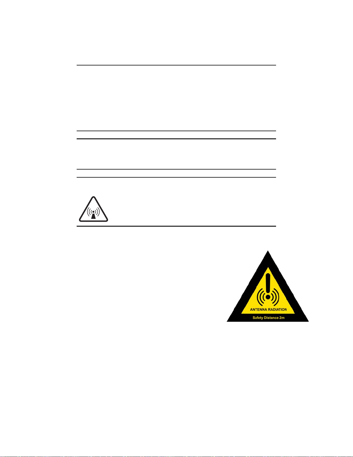
CAUTION
This device emits radio frequency energy when in transmit
mode. To avoid injury, keep at least 2 meters away from the
antenna when the system is operational.
Product warning label
This safety alert label is affixed to the antenna radome:
Step A: Unpacking the installation kit
Unpack the Hughes 9250 Kit (3500129-0010) and make sure you have the three sub kits and the following
parts:
• Parts included in the Tracking Antenna Kit (3500128-0001)
– BGAN Land Mobile Tracking Antenna
– Auxiliary Control Unit (ACU)
– Four-foot RF cable for the connection between terminal and ACU (RG223 with SMA connectors)
– Eighteen-foot RF cable for the connection between ACU and antenna (RG223 with TNC
connectors)
– Three magnetic feet with washers and nuts
2 3500145-0001 Revision A
Page 3
• Hughes 9250 Installation Kit (3500059-0010)
– Hughes 9250 terminal (3500058-0010)
– DC/DC power supply (9501495-0001)
– Serial data cable (3500125-0001)
– Two Ethernet/ISDN cables for user terminal connections (9501246-0002)
– Battery (3500065-0001)
– CD-ROM with LaunchPad MMI software (3500066-0001)
– DC power extension cable with filter (
• Vehicular Install Kit (3500158-0001)
– Vehicular install bracket (3500156-0001)
– Accessory mounting plate (3500155-0001)
– Mounting hardware
3500151-0001)
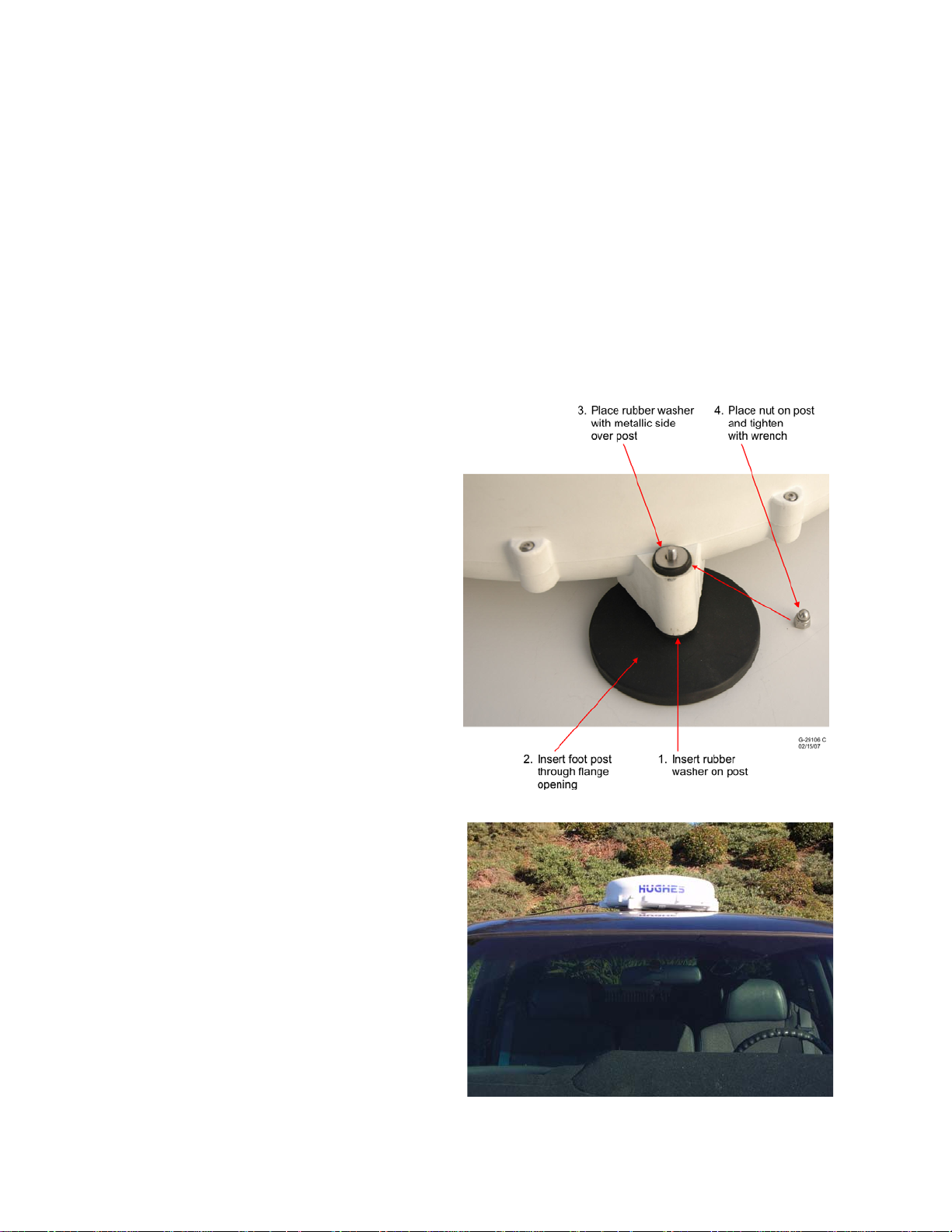
Step B: Installing the magnetic mount
feet
Assemble the three magnetic feet and secure them
to the antenna using an 8 mm nut and wrench as
shown here.
Step C: Positioning and mounting the
antenna
Mount the antenna on the roof of the vehicle and
away from other installed devices that may
obstruct the line of sight between the antenna and
the satellite. The rubber pads of the magnetic
mounts must make full contact with the vehicle's
metal roof.
Orient the antenna connectors in the direction of
the cable run to the terminal.
3500145-0001 Revision A 3
Page 4

Step D: Positioning and mounting the terminal
Position the terminal inside the passenger
compartment or storage area of the vehicle.
Ensure the terminal and ACU are within reach
of a 12 Vdc outlet.
Use the vehicle installation bracket as shown
here to attach the terminal to the vehicle.
Step E: Connecting the cables
Note: Do not connect power to the terminal until Step H.
The cables connecting components of the terminal
can be connected in any order. Follow the steps
below and the two reference figures to connect the
components.
4 3500145-0001 Revision A
Page 5

1. Connect the 4-foot RF cable between the Hughes 9250 and the ACU. Securely fasten the cable to the
9250 with the vehicle mounting kit. The connection to the ACU is labeled TERMINAL RF.
2. Connect the 18-foot RF cable between the ACU and the Tracking Antenna. Ensure any slack in the
cable is within the vehicle. The connection to the ACU is marked ANTENNA.
3. Connect the serial control cable between the 9250 serial port and the ACU labeled COM RS232.
4. Connect the Ethernet cable between the 9250 Ethernet port and the Terminal Equipment (such as a
laptop computer).
5. Insert the power supply plug to the ACU.
6. Insert the 9250 power supply from the ACU.
Note: The Hughes 9250 serial port uses a USB Type A connector but it is not a
USB port.
3500145-0001 Revision A 5
Page 6

Step F: Installing the terminal’s SIM card and battery
1. Position the terminal so the battery door is facing
you.
2. Open the battery door.
3. If you have already installed the battery, release and
remove it.
4. Push the button on the left side of the USIM/SIM
card holder to release the holder from its slot.
5. Insert the USIM/SIM card into the card holder
ensuring that it snaps into place.
6. With the card in place, orient the holder with the card's gold
contacts facing down. Insert the holder back into the slot in the
terminal.
6 3500145-0001 Revision A
Page 7

7. Insert the battery into its slot in the terminal and lock it in place. Close and
lock the battery door.
Step G: Mounting parts on the accessory mounting plate
Use the parts in the
vehicular install kit
(stand off, screws,
lock washers, and tie
wraps) to mount the
parts to the accessory
mounting plate.
Step H: Connecting power
Insert the power supply plug into the vehicle 12 Vdc accessory outlet. This can be done with or without
initial power to the 12 Vdc outlet supply
Note: You can operate the terminal without a battery, but Hughes recommends operation
with a battery installed for a graceful power down if power is disconnected.
The terminal cannot operate solely on battery power. The antenna requires power from the
vehicular power source.
The terminal can be operated while the battery is charging.
Your vehicle's battery may be drained if the terminal is used without running the engine.
3500145-0001 Revision A 7
Page 8

Step I: Connecting to the Internet
After power is applied, the Hughes 9250 terminal and antenna begin their startup sequence. The tracking
antenna begins its search for the BGAN satellite. The antenna motors may be heard during this time.
Note: The antenna must have line of sight to the BGAN satellite to lock onto the
satellite signal.
Refer to the Hughes 9250 Terminal User Guide included on the CD to learn more about how to use the
Hughes 9250 Land Mobile Satellite Terminal.
Refer to the Hughes 9201 Terminal User Guide for instructions on how to connect a PC or Mac to the
terminal. However, note the following differences/limitations between the 9201 and 9250 for internet
connection and performance:
• The antenna pointing procedure is bypassed. The Hughes 9250 terminal automatically registers with
the network after the tracking antenna acquires the satellite signal.
• The 9250 operates as a class-2 modem, that is, streaming class connection is limited to a maximum
128 kbps data rate.
• Only “best effort” performance can be expected under moving conditions due to the higher probability
of obstruction of satellite signal and limitations of the current BGAN system.
• "Best effort" performance can also be expected with look angles lower than 20 degrees.
• Signal outages of more than 3 seconds cause circuit switched calls to drop and packet switched
sessions to pause. User intervention may be required to reactivate connections for longer outage
durations.
• Beam-to-beam handover is not supported by the network until BGAN-X is completed.
• The 9250 is fully BGAN-X Class 11 compatible with a software upgrade.
Customer support
Contact Hughes at (858) 452-4658
Coverage Map
The Hughes 9250 performs best in areas where the antenna elevation angle is 20 degrees or higher. Lower
elevation angles increase the probability of signal outages caused by trees, buildings and hilly terrain and
may severely impact the usability on the move. See the figure below for a rough estimate of elevation in
your location.
8 3500145-0001 Revision A
Page 9

3500145-0001 Revision A 9
Page 10

Copyright © 2007 Hughes Network Systems, LLC
All rights reserved. This publication and its contents are proprietary to Hughes Network Systems, LLC. No part of this publication may be reproduced in
any form or by any means without the written permission of Hughes Network Systems, LLC, 11717 Exploration Lane, Germantown, Maryland 20876.
Hughes Network Systems, LLC has made every effort to ensure the correctness and completeness of the material in this document. Hughes Network
Systems, LLC shall not be liable for errors contained herein. The information in this document is subject to change without notice. Hughes Network
Systems, LLC makes no warranty of any kind with regard to this material, including, but not limited to, the implied warranties of merchantability and
fitness for a particular purpose.
Trademarks
Hughes and Hughes Network Systems are trademarks of Hughes Network Systems, LLC. All other trademarks are the property of their respective
owners.
10 3500145-0001 Revision A
 Loading...