

Page 1
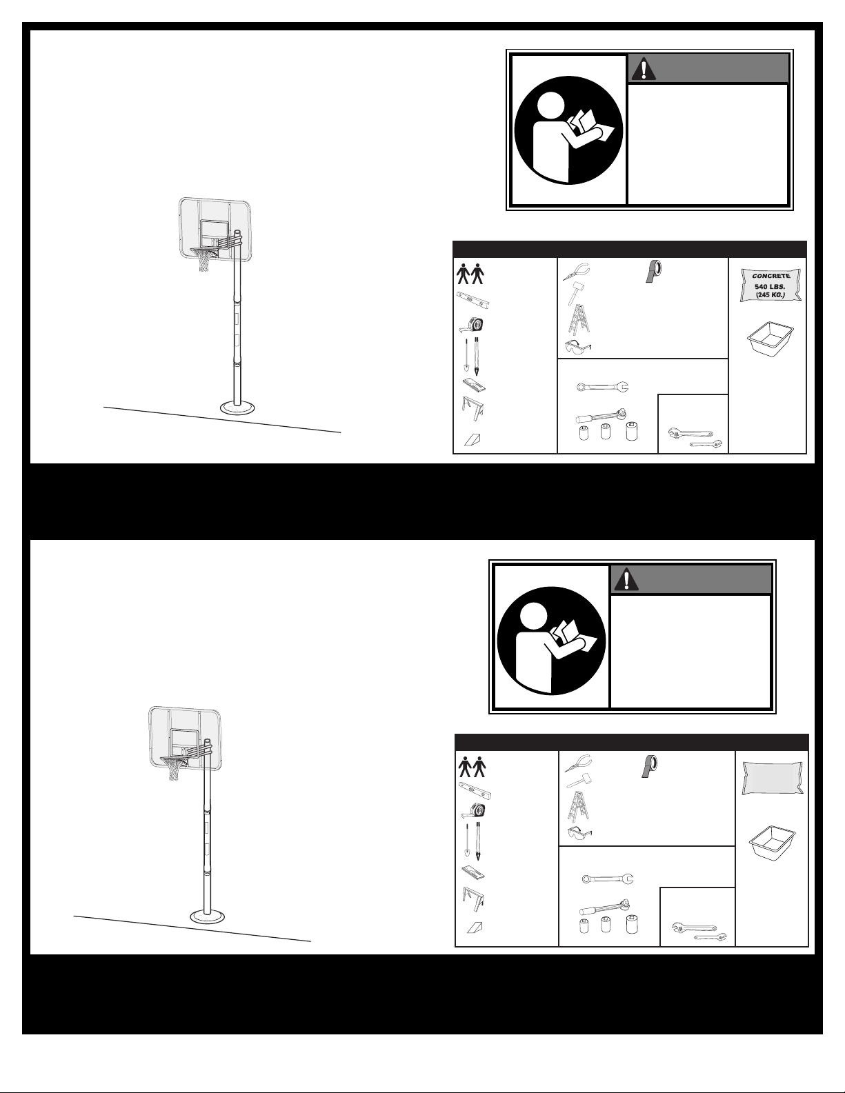
Inground System
Owners Manual
Customer Service Center
• N53 W24700 South Corporate Circle • Sussex, WI 53089 •
U.S.A.
R
O
BEFORE USING THIS UNIT.
F
OPERATING INSTRUCTIONS
C
OR DAMAGE TO PROPERTY.
REQUIRED TOOLS AND MATERIALS:
• P
• 2 People
• Carpenter’s Level
• 15’ Tape Measure
• Shovel & Post Hole
Digger
• Wood Board (scrap)
• Sawhorse or
Support Table
Wedge
•
• (2 each) Wrenches and/or Socket Wrenches and
liers
• Hammer
• Stepladder 8 ft. (2.4 m)
• Safety Goggles
Sockets (Deep-Well Sockets are Recommended).
1/2" 9/16" 3/4"
1
/2"9/16"3/4"
WARNING!
EAD AND UNDERSTAND
PERATOR'S MANUAL
AILURE TO FOLLOW
OULD RESULT IN INJURY
• Heavy Duty Tape
•
• Container to Mix
• Optional: Large &
Small Adjustable
Wrenches
Toll-Free Customer Service Number for U.S: 1-800-558-5234,
For Canada: 1-800-284-8339,
For Europe: 00 800 555 85234 (Sweden: 009 555 85234),
For Australia: 1-800-632 792
Internet Address: http://www.huffysports.com
Sistema de fijación en el piso
Manual del propietario
Centro de Servicio al Cliente
o N53 W24700 South Corporate Circle o Sussex, WI
53089 o EE.UU.
¡ADVERTENCIA!
LEA Y ENTIENDA EL MANUAL
DEL OPERADOR ANTES DE
USAR ESTA UNIDAD.
SI NO SE SIGUEN LAS
INSTRUCCIONES DE
OPERACIÓN SE PODRÍA
OCASIONAR UNA LESIÓN O
DAÑOS A LA PROPIEDAD.
HERRAMIENTAS Y MATERIALES REQUERIDOS:
• 2 personas
• Nivel de carpintero
Cinta de medir de
•
15' (4.57 m)
• Pala y excavador
del orificio para el
poste
• Tabla de madera
(un trozo)
• Caballete o mesa
de apoyo
Cuña
•
• Alicates
• Martillo
• Escalera de 8 pies (2.4 m)
Gafas de seguridad
•
• (2 de cada una) llaves de tuercas y/o llaves de
tuercas de boca tubular y casquillos (se
recomiendan casquillos profundos).
1/2" 9/16" 3/4"
1/2" 9/16" 3/4"
• Cinta adhesiva fort
• Opcional: llaves de
tuercas ajustables
grandes y pequeñas
540 LIBRAS
•
(245 KG) DE
CONCRETO
• Recipiente para
mezclar
© COPYRIGHT 2005 by SPALDING
Número telefónico gratuito de servicio al cliente en EE. UU.: 1-800-558-5234,
Para Canadá: 1-800-284-8339,
Para Europa: 00 800 555 85234 (Suecia: 009 555 85234),
Para Australia: 1-800-632 792
Dirección en Internet: http://www.huffysports.com
1
12/05 P/N M880102
Page 2
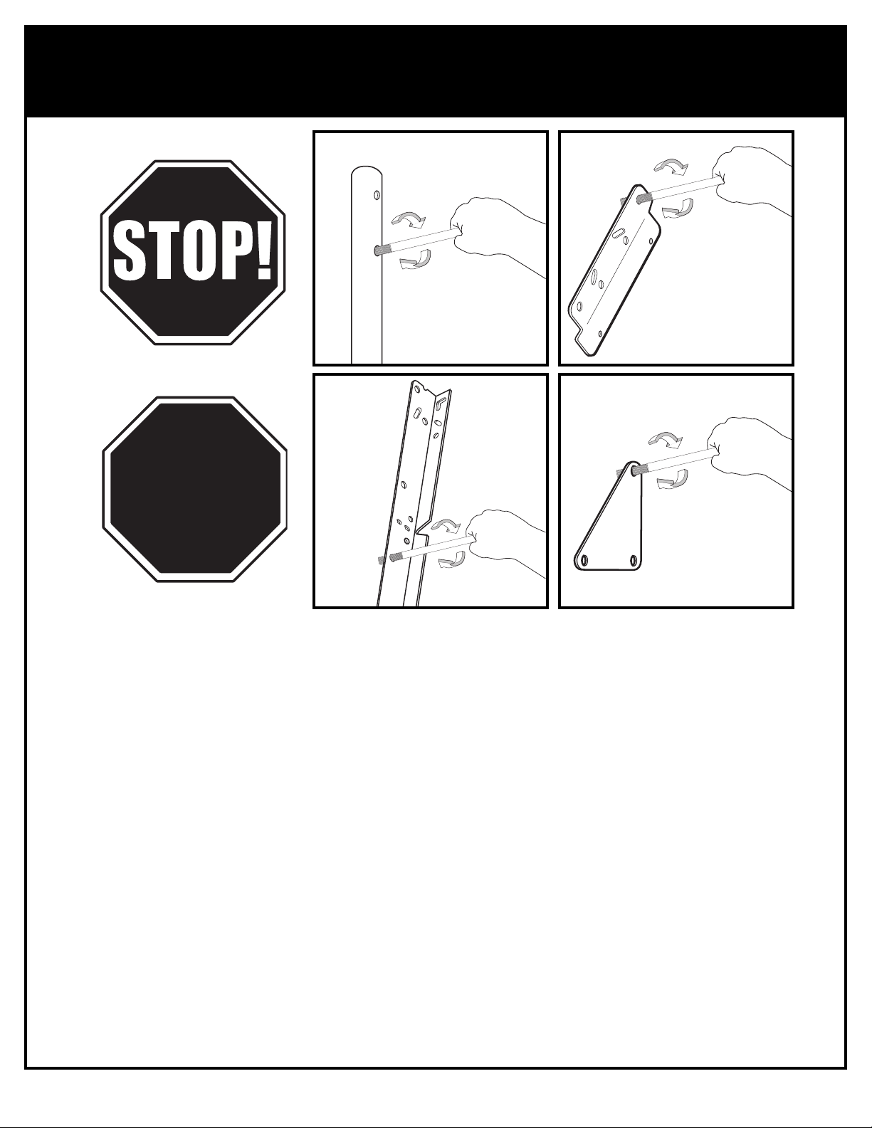
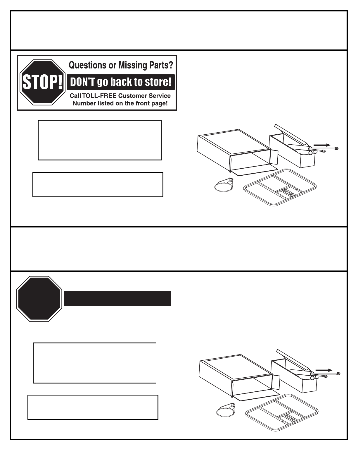
BEFORE YOU START!
ALTO!
¿Tiene preguntas o le faltan piezas?
¡NO regrese a la tienda!
¡Llame al número telefónico GRATUITO de Servicio
al Cliente que se indica en la primera página!
¡ALTO!
¡ANTES DE COMENZAR!
To ensure optimal playability of backboard system, a close tolerance fit between the elevator
components and hardware is required. Test-fit large bolts into large holes of elevator tubes,
backboard brackets, and triangle plates. Carefully rock them in a circular motion to ream out
Para asegurar el óptimo rendimiento del sistema del respaldo en el juego, se requiere un
ajuste de tolerancia estrecha entre los componentes del elevador y el herraje. Pruebe el
ajuste de los pernos grandes en los orificios grandes de los tubos elevadores, soportes del
respaldo y placas triangulares. Cuidadosamente muévalos en círculos para eliminar cualquier
any excess paint from holes if necessary.
Not all items pictured are included with every model.
exceso de pintura, si es necesario.
No todos los artículos ilustrados se incluyen con cada modelo.
P/N M880102 12/05
2
Page 3
Owner must ensure that all players know and follow these rules
for safe operation of the system.
WARNING
•
DO NOT HANG on the rim or any part of the system including
backboard, support braces or net.
•
During play, especially when performing dunk type activities,
keep player's face away from the backboard, rim and net.
Serious injury could occur if teeth/face come in contact with
backboard, rim or net.
•
Do not slide, climb, shake or play on base and/or pole.
•
When adjusting height or moving system, keep hands and
fingers away from moving parts.
•
Do not allow children to move or adjust system.
•
During play, do not wear jewelry (rings, watches, necklaces,
etc.). Objects may entangle in net.
•
Keep organic material away from pole base. Grass, litter, etc.
could cause corrosion and/or deterioration.
•
Check pole system for signs of corrosion (rust, pitting,
chipping) and repaint with exterior enamel paint. If rust has
penetrated through the steel anywhere, replace pole
immediately.
•
Check system before each use for proper ballast, loose
hardware, excessive wear and signs corrosion and repair
before use.
•
Check system before each use for instability.
•
Never play on damaged equipment.
•
Keep pole top covered with cap at all times.
•
See instruction manual for proper installation and
maintenance.
R
ead and understand warnings listed
below before using this product
.
F
ailure to follow these warnings may
result in serious injury and/or
property damage
.
ID#: 588000 05/05
MUNSELL NOTATION
Hue Value Chroma
5.0 YR 6.0/15
Equiv. CIE Data
(Y%) x y
30.05 0.5510 0.4214
Approx. PMS Color
13 parts yellow
3 parts Warm Red
1/4 part Black
Warning Area = Orange
Size = 4" x 6.5"
Corner Radius = 3/8"
Die Cut Label
3.25 Mil Vinyl
All Temp. Permanent Adhesive
1 Mil. Polypropolyne Overlaminate
Illustrator 8.0 = EPS
Backing + 1/16 Circumference
Rolls of 500
In the U.S.: 1-888-713-5488
I
n the U.S.: 1-800-558-5234
I
n Canada: 1-800-284-8339
In the U.S.: 1-800-334-9111
In the U.S.: 1-800-558-5234
In Canada: 1-800-284-8339
MUNSELL NOTATION
Hue Value Chroma
5.0 YR 6.0/15
Equiv. CIE Data
(Y%) x y
30.05 0.5510 0.4214
Approx. PMS Color
13 parts yellow
3 parts Warm Red
1/4 part Black
Warning Area = Orange
Size = 4" x 6.5"
Corner Radius = 3/8"
Die Cut Label
3.25 Mil Vinyl
All Temp. Permanent Adhesive
1 Mil. Polypropolyne Overlaminate
Illustrator 8.0 = EPS
Backing + 1/16 Circumference
Rolls of 500
El propietario debe asegurarse de que todos los jugadores conozcan y
obedezcan estas reglas para la operación segura del sistema.
•
NO SE CUELGUE del borde ni de ninguna parte del sistema, inclusive el
respaldo, las abrazaderas de apoyo y la red.
•
Durante el juego, especialmente cuando se realizan actividades de tipo clavada
(dunk), el jugador debe mantener la cara alejada del respaldo, el borde y la red.
Si los dientes o la cara entran en contacto con el respaldo, el borde o la red, se
puede sufrir una lesión grave.
•
Durante el juego, especialmente cuando se realizan actividades de tipo clavada
(dunk), el jugador debe mantener la cara alejada del respaldo, el borde y la red.
Si los dientes o la cara entran en contacto con el respaldo, el borde o la red, se
puede sufrir una lesión grave.
•
No se deslice, suba, sacuda ni juegue en el poste.
•
Al ajustar la altura mantenga las manos y los dedos alejados de las partes
movibles.
•
No permita que los niños muevan o ajusten el sistema.
•
Durante el juego, no use joyería (anillos, relojes, collares, etc.) Estos objetos se
podrían atorar en la red.
•
Mantenga los materiales orgánicos alejados de la base del poste. El césped, la
basura, etc. podrían causar corrosión y/o deterioro de la base del poste.
•
Revise que el sistema del poste no tenga señales de corrosión (oxidación,
picaduras, desconchaduras) y si las tiene vuelva a pintarlo con pintura de
esmalte para exteriores. Si la corrosión penetró a través del acero en cualquier
área, reemplace inmediatamente el poste.
•
Antes de cada uso revise el sistema para verificar que esté adecuadamente
equilibrado, que no tenga herraje suelto, desgaste excesivo ni signos de
corrosión, y repárelo si es necesario.
•
Verifique la estabilidad del sistema antes de cada uso.
•
Nunca juegue en equipo dañado.
•
Siempre mantenga la parte superior del poste cubierta con las tapas.
ADVERTENCIA
Lea y
entienda las advertencias que se
encuentran a continuación antes de
usar este producto
.
S
i no se observan estas advertencias se
podrían causar lesiones graves y/o
d
a
ñ
o
s
m
ateriales
.
N/P: 588000 05/05
En EE.UU.: 1-888-713-5488
E
n EE.UU.: 1-800-558-5234
En Canadá: 1-800-284-8339
En EE.UU.: 1-800-334-9111
E
n EE.UU.: 1-800-772-5346
3
12/05 P/N M880102
Page 4
Size = 2-3/4" x 4
Corner Radius = 3/8"
Die Cut Label
3.25 Mil Vinyl
All Temp. Permanent Adhesive
1 Mil. Polypropolyne Overlaminate
Illustrator 8.0 = EPS
Backing + 1/16 Circumference
Rolls of 500
204316 10/04
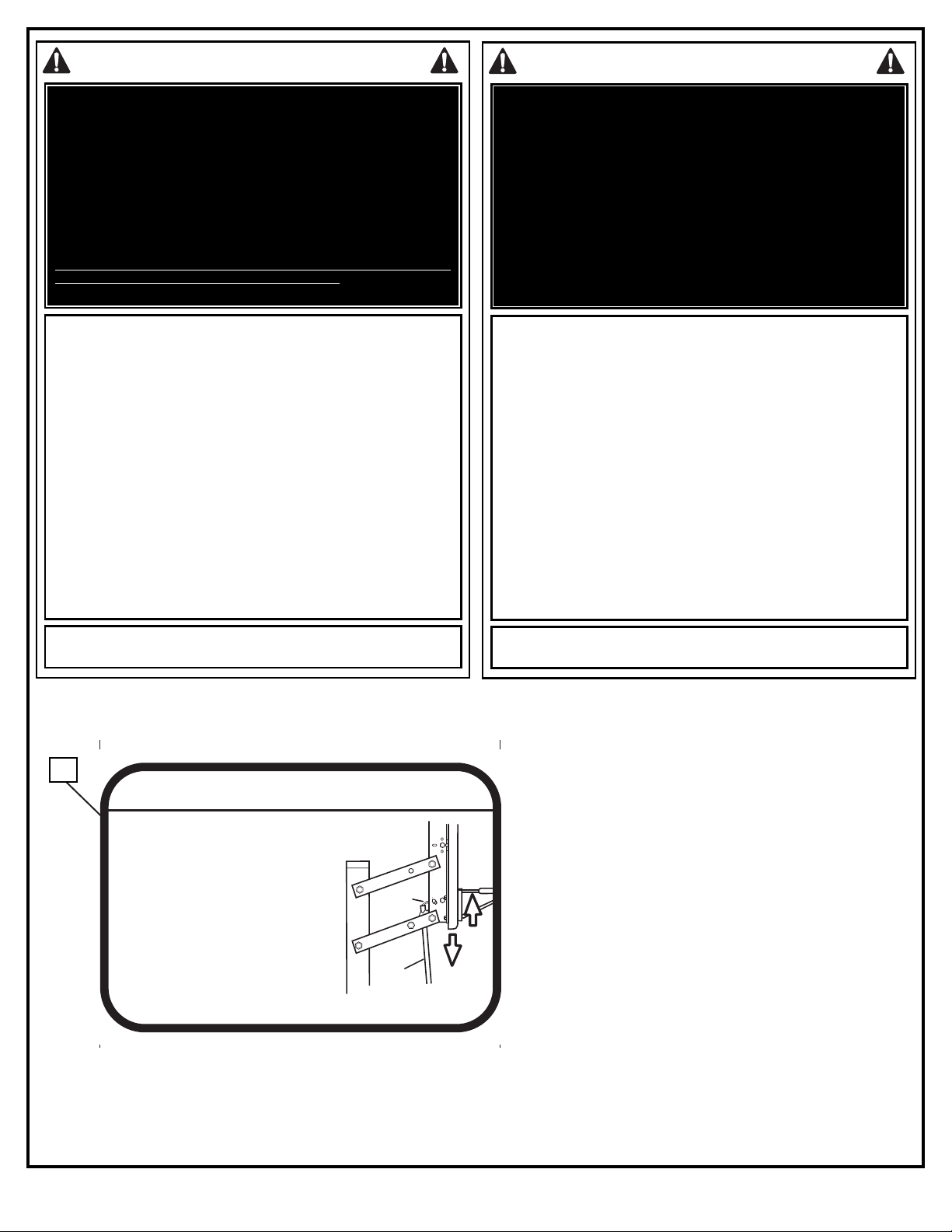
HEIGHT ADJUSTMENT
TO ADJUST BACKBOARD:
1. TO RAISE BACKBOARD:
Slowly push up on the rim broom
handle or wooden dowel,
3/4”- 7/8” (19mm - 22mm) diameter
as shown to engage locking
mechanism at desired height.
2. TO LOWER BACKBOARD:
Push lever up to unlock and
carefully lower backboard to lowest
position.
with
LEVER
1
2
BROOM
HANDLE
SAFETY INSTRUCTIONS
INSTRUCCIONES DE SEGURIDAD
AILURE TO FOLLOW THESE SAFETY INSTRUCTIONS MAY RESULT IN
F
SERIOUS INJURY, PROPERTY DAMAGE AND WILL VOID WARRANTY.
Owner must ensure that all players know and follow these rules for safe
o ensure safety, do not attempt to assemble this system without following
T
the instructions carefully. Proper and complete assembly, use and
supervision is essential for proper operation and to reduce the risk of
ccident or injury. A high probability of serious injury exists if this system is
a
not installed, maintained, and operated properly. Check entire box and
inside all packing material for parts and/or additional instructional material.
Before beginning assembly, read the instructions and identify parts using
the hardware identifier and parts list in this document.
• If using a ladder during assembly, use extreme caution.
• Two (2) people are recommended for this operation.
• Seat the pole sections properly. Failure to do so could allow the pole
sections to separate during play.
• Before digging, contact utility company to locate underground power
cables, gas, and water lines. Ensure there are no overhead power
lines within 20 ft. (7 m) radius of pole location.
• Climate, corrosion, excessive use, or misuse could result in system
failure.
• If technical assistance is required, contact Huffy Sports.
• Minimum operational height is 6'6" (1.98 m) to the bottom of
backboard.
• This equipment is intended for home recreational use only and NOT
excessive competitive play.
• Read and understand the warning label affixed to pole.
• The life of your basketball pole depends on many conditions. The
climate, placement of the pole, the location of the pole, exposure to
corrosives such as pesticides, herbicides, or salts are all important.
• Adult supervision is recommended when adjusting height.
• Serious injury could occur if teeth/face come in contact with
backboard, net, or rim.
operation of the system.
EL INCUMPLIMIENTO DE ESTAS INSTRUCCIONES DE SEGURIDAD PUEDE
DAR COMO RESULTADO LESIONES GRAVES, DAÑOS MATERIALES Y
El propietario debe asegurarse de que todos los jugadores conozcan y
obedezcan estas reglas para la operación segura del sistema.
Por su seguridad, no intente montar este sistema sin seguir cuidadosamente
las instrucciones. Es esencial el montaje completo, y el uso y la supervisión
adecuados para la operación correcta del sistema y para reducir el riesgo de
accidentes o lesiones. Existe una alta probabilidad de sufrir lesiones graves
si este sistema no se instala, mantiene y opera adecuadamente. Revise toda
la caja y el interior de todo el material de embalaje para encontrar todas las
piezas y/o material instructivo adicional. Antes de comenzar el montaje, lea
las instrucciones e identifique las piezas usando el identificador de herraje
y la lista de piezas contenidos en este documento.
•
Si utiliza una escalera de mano durante el montaje, tenga mucho cuidado.
• Se recomienda que dos (2) personas realicen esta operación.
• Asiente correctamente las secciones del poste. Si no lo hace, las secciones
d
el poste podrían separarse durante el juego.
• Antes de excavar, comuníquese con las compañías de servicios públicos
para ubicar los cables eléctricos y las tuberías de gas y de agua
subterráneos. Asegúrese de que no haya líneas eléctricas suspendidas en un
radio de 20 pies (7 m) de la ubicación del poste.
• El clima, la corrosión, el uso excesivo y el mal uso podrían ocasionar la falla
d
el sistema.
• Si requiere asistencia técnica, comuníquese con Huffy Sports.
• La altura mínima de operación es de 6 pies y 6 pulgadas (1.98 m) hasta la
parte inferior del respaldo.
•
Este equipo está diseñado únicamente para uso recreativo en el hogar y NO
para juego competitivo excesivo.
• Lea y entienda la etiqueta de advertencia adherida en el poste.
• La vida útil de su poste de baloncesto depende de muchas condiciones. El
clima, la colocación del poste, la ubicación del poste, la exposición a
sustancias corrosivas tales como pesticidas, herbicidas o sales son factores
importantes.
• Se recomienda que el ajuste de la altura se realice bajo la supervisión de un
adulto.
• Si los dientes o la cara entran en contacto con el respaldo, la red o el borde,
se puede sufrir una lesión grave.
ANULARÁ LA GARANTÍA.
Most injuries are caused by misuse and/or not following instructions.
Use caution when using this system.
14
P/N M880102 12/05
La mayoría de las lesiones son causadas por el uso inadecuado y/o por el
incumplimiento de las instrucciones. Tenga cuidado cuando use este sistema.
1. PARA ELEVAR EL RESPALDO:
Levante lentamente el borde con el palo de
una escoba o con un tarugo de madera de
19mm a 22mm (de 3/4” a 7/8”) de diámetro
como se muestra, p
ara embragar el
mecanismo de fijación a la altura deseada.
2. PARA BAJAR EL RESPALDO:
Empuje la p
el seguro y cuidadosamente baje el
alanca hacia arriba para liberar
respaldo hasta su posición más baja.
4
Page 5
¿Tiene preguntas o le faltan piezas?
¡Llame al número telefónico GRATUITO de Servicio
al Cliente que se indica en la primera página!
¡ALTO!
¿Tiene preguntas o le faltan piezas?
¡Llame al número telefónico GRATUITO de Servicio
al Cliente que se indica en la primera página!
¡NO regrese a la tienda!
¡NO regrese a la tienda!
¡¡ALTO!ALTO!
NOTICE TO ASSEMBLERS
ALL Basketball Systems, including those used for DISPLAYS, MUST be assembled and ballasted
with sand, water or concrete according to the instructions. Failure to follow instructions could
result in SERIOUS INJURY. It is NOT acceptable to devise a makeshift weight system.
IMPORTANT!
Remove all contents from boxes.
Be sure to check inside pole sections;
hardware and additional parts are
packed inside.
WARRANTY CARD:
Please remember to complete your product
registration form either on-line at:
www.huffysports.com or mail-in the
enclosed postcard.
For more information on assembly, placement, proper
use, and maintenance, visit The American Basketball
Council website at http://www.smarthoops.com.
AVISO PARA LAS PERSONAS QUE REALIZAN EL MONTAJE
TODOS los sistemas de baloncesto, inclusive los usados para EXHIBICIÓN, DEBEN estar montados y
equilibrados con arena, agua o concreto de acuerdo con las instrucciones. Si se ignoran est
instrucciones se podría ocasionar una LESIÓN GRAVE. NO es aceptable improvisar un sistema de pesas
provisional.
¡IMPORTANTE!
Saque todo el contenido de las cajas.
Asegúrese de revisar el interior de las
secciones del poste.
acado herraje y piezas
adicionales.
TARJETA DE GARANTÍA:
Por favor recuerde completar su formulario
de registro del producto, ya sea en línea en:
www.huffysports.com o por correo en la
tarjeta postal adjunta.
Si desea más información sobre el montaje, colocación,
uso y mantenimiento adecuados, visite el sitio en la
Web del American Basketball Council en
http://www.smarthoops.com.
Ahí se han emp
as
5
12/05 P/N M880102
Page 6
PARTS LIST - See Hardware Identifier
Item Qty. Part No. Description
1 1 908143 Top Pole Section
2 1 90812501 Middle Pole Section
3 1 928407 Bottom Pole Section
4 2 202800 Ground Sleeve Half
5 1 202801 Ground Sleeve Cap
6 1 203279 Anti-Skid Tape
7 2 90096401 Backboard Bracket (Black)
8 2 204159 Clip, Plastic, Rebar Holder
9 1 903601 Rebar, Reinforcement Bar
10 5* 203063 Nut, Ny-lock, 3/8-16
11 4 904807 Elevator Tube (Black)
12 1* 206360 Bolt, Hex-Head, 3/8-16 x 2.625” Long
13 1 108142 Pawl Lever
14 1 204316 Label, Ratchet Elevator Opperation
15 2 108144 Bracket, Support
16 2 808152 Ratchet, Stamped
17 2 202603 Washer, Flat, Nylon
18 2 204321 Spacer, Steel .75 O.D. x 1.19" Long
19 2 201436 Spacer, Plastic, .75" Long
20 5 201640 Bolt, Hex-Head, 1/2-13 x 7.25" Long
Qty. Part No. Description
Item
21 5 206340 Locknut, Hex Centerlock, 1/2-13
22 2 202587 Spacer, Plastic, 1" Long
23 1 206305 Pin, Clevis
24 2 206303 Washer, 0.25", Flat
25 1 201129 Spacer, 1.8 long x .402 I.D. x .5 O.D.
26 1 201125 Spring, Ratchet Return
27 4 205528 Bolt, Hex-Head, 5/16-18 x 1" Long
28 1 203796 T-Bolt, 3/8-16 x 5" Long
29 1 900033 Bracket, Slam Jam
30 2 201681 Spacer, Black, Plastic, .88" Long
31 1 207103 Pole Cap
32 1 Rim
33 1 200318 Bracket, S/J Reinforcement
34 1 203472 Spring, Black, Slam Jam
35 1 203470 Washer, Flat, Slam Jam
36 1 203795 Nut, Special, Slam Jam
37
38 1 Net
39 4* 203100 Nut, Hex-Flange, 5/16-18
40 Backboard
* You may have extra parts with this model.
4 204961 Bolt, Hex Head, 3/8-16 x 5/8” Long
LISTA DE PIEZAS - Vea el identificador de herraje
Artículo Cant. Pieza
1 1 908143
2 1 90812501 Sección media del poste
3 1 928407 Sección inferior del poste
4 2 202800 Mitad de la manga del piso
5 1 202801 Tapa de la manga del piso
6 1 203279 Cinta antiderrapante
7 2 90096401 Soporte del tablero (negro)
8 2 204159 Sujetador, plástico, sujetador de la
9 1 903601 Barra de refuerzo
10 5* 203063 Tuerca, Ny-lock, 3/8-16
11 4 904807 Tubo elevador (negro)
12 3* 206360 Perno, cabeza hexagonal, 3/8-16
13 1 108142 Palanca con fiador
14 1 204316 Etiqueta, operación del elevador
15 2 108144 Soporte
16 2 808152 Trinquete, estampado
17 2 202603 Arandela plana de nilón
18 2 204321 Espaciador de acero, 0.75 D.E. x
19 2 201436 Espaciador, plástico, 0.75" de
20 5 201640 Perno, cabeza hexagonal, 1/2-13
N.º Descripción
Sección superior del poste
barra de refuerzo
x 2.625” de longitud
de trinquete
1.19" de longitud
longitude
x 7.25" de longitud
Artículo
Cant. Pieza
21 5 206340
22 2 202587 Espaciador, plástico, 1" de
23 1 206305 Pasador de horquilla
24
25 1 201129 Espaciador, 1.8 de longitud x
26
27 4 205528 Perno, cabeza hexagonal,
28 1 203796 Perno T, 3/8-16 x 5" de longitud
29 1 900033 Soporte Slam Jam
30 2 201681 Espaciador, plástico, negro, 0.88"
31 1 207103 Tapa del poste
32 1 Borde
33 1 200318 Soporte, refuerzo S/J
34 1 203472 Resorte, negro, Slam Jam
35 1 203470 Arandela plana, Slam Jam
36 1 203795 Tuerca, especial, Slam Jam
37
38 1 Red
39 4* 203100 Tuerca, brida hexagonal, 5/16-18
40 1 Respaldo
2 206303 Arandela plana, 0.25"
1 201125 Resorte de retorno del trinquete
4 204961 Perno, cabeza hexagonal,
N.º Descripción
Contratuerca central hexagonal,
1/2-13
longitude
0.402 D.I. x 0.5 D.E.
5/16-18 x 1" de longitud
de longitud
3/8-16 x 5/8” de longitud
P/N M880102 12/05
* Puede haber piezas adicionales en este modelo.
6
Page 7
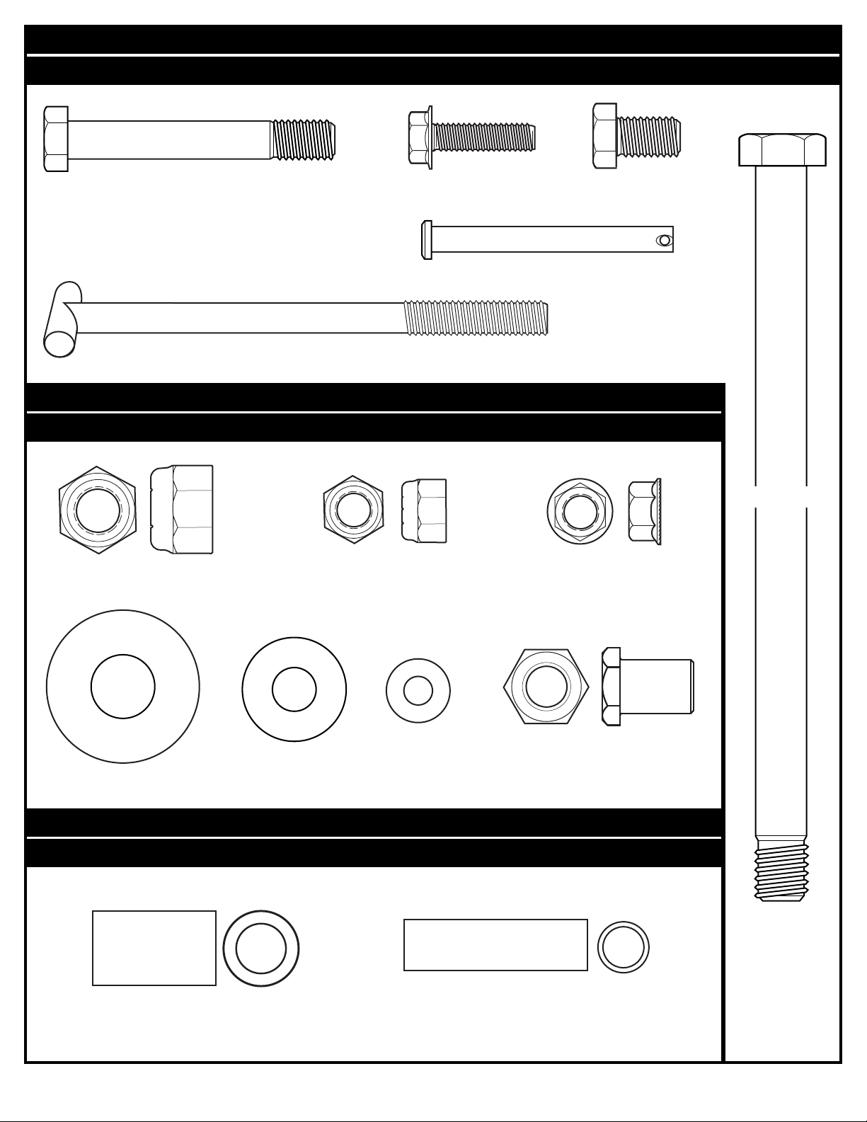
HARDWARE IDENTIFIER (BOLTS & SCREWS)
IDENTIFICADOR DE HERRAJE (PERNOS Y TORNILLOS)
#12 (1)*
#27 (4)
Item #23 (1)
#28 (1)
HARDWARE IDENTIFIER (NUTS & WASHERS)
IDENTIFICADOR DE HERRAJE (TUERCAS Y ARANDELAS)
#21 (5)
#10 (5)*
#37 (4)
Item #20 (5)
#39 (4)*
#17 (2)
#35 (1)
HARDWARE IDENTIFIER (METAL SPACERS)
IDENTIFICADOR DE HERRAJE (ESP
#18 (2)
#24 (2)
#36 (1)
ACIADORES DE METAL)
#25 (1)
* You may have extra parts with this model.
* Puede haber piezas adicionales en este modelo.
7
12/05 P/N M880102
Page 8
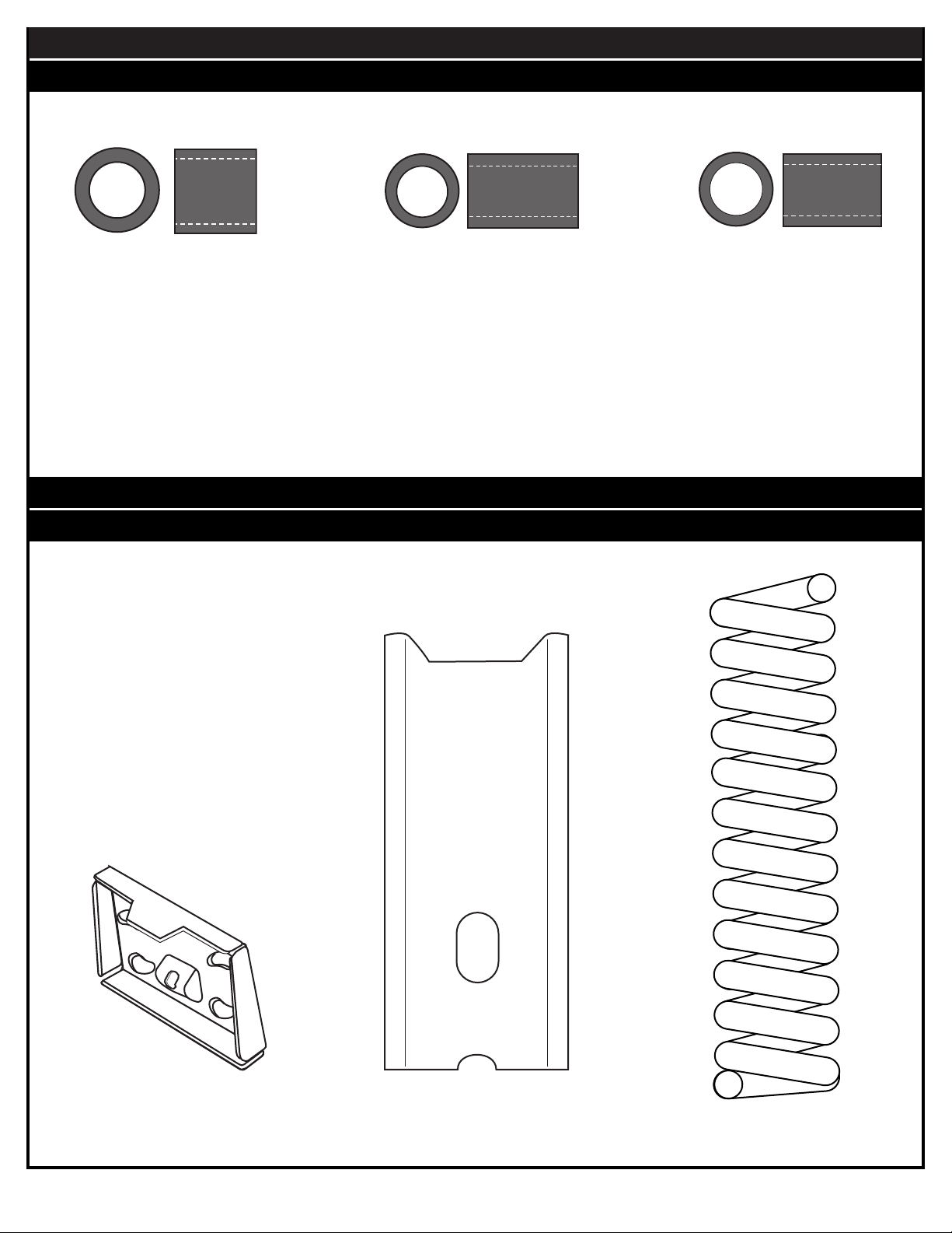
HARDWARE IDENTIFIER (PLASTIC SPACERS & CLIPS)
IDENTIFICADORES DE HERRAJE (ESPACIADORES Y SUJETADORES DE PLÁSTICO)
#19 (2)
#22 (2)
HARDWARE IDENTIFIER (OTHER)
IDENTIFICADOR DE HERRAJE (OTROS)
#30 (2)
#29 (1)
P/N M880102 12/05
#33 (1)
#34 (1)
8
Page 9
SECTION A: ASSEMBLE THE POLE
CONCRETE
SECCIÓN A: MONTAJE DEL POSTE
This is what your system will look like when you’ve finished this section.
Así es como se verá su sistema cuando haya terminado esta sección.
TOOLS REQUIRED FOR THIS SECTION
HERRAMIENTAS REQUERIDAS PARA ESTA SECCIÓN
Shovel and Post Hole Digger
Pala y excavador del orificio para el poste
Carpenter's Level
Nivel de carpintero
CONCRET
Container to Mix
Recipiente para mezclar
O
9
12/05 P/N M880102
Page 10
18" (42.7 cm)
6" (15.2 cm)
24" (61 cm)
C
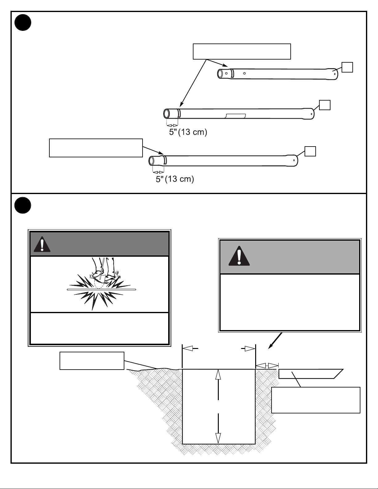
1.
orrectly identify each pole section.
Identifique correctamente cada sección del poste.
Identification Sticker
Calcomanías de identificación
Identification Sticker
Calcomanías de identificación
1
TOP / SUPERIOR
2
MIDDLE / MEDIA
3
BOTTOM / SECCIÓN INFERIOR
Ensure ground is level with playing surface, then dig pole hole.
2.
Asegúrese de que el piso esté nivelado con la superficie de juego y luego haga el orificio para el poste.
WARNING!
¡ADVERTENCIA!
IMPORTANT!
¡IMPORTANTE!
Maximum distance from edge of hole to
edge of playing surface 6” (15.2 cm).
La distancia máxima desde el borde del
CONTACT UTILITIES BEFORE DIGGING.
COMUNÍQUESE CON LAS COMP
DE SERVICIO ANTES DE EXCAVAR.
GROUND SURFACE
SUPERFICIE DEL PISO
AÑÍAS
orificio hasta el borde de la superficie de
juego debe ser de 6" (15,2 cm).
PLAYING SURFACE
SUPERFICIE DE JUEGO
P/N M880102 12/05
10
Page 11

Snap two halves of ground sleeve (4) together. Insert and secure
3.
b
ottom pole section (3) into ground sleeve (4) by tightening
ground sleeve cap (5).
Conecte las dos mitades de la manga del piso (4). Introduzca y
fije la sección inferior del poste (3) en la manga del piso (4)
apretando la tapa de la manga del piso (5).
NOTE:
NOTA:
3
Flared end goes inside
ground sleeve.
El extremo abocinado
debe quedar dentro de la
manga del piso.
Fill hole approximately 1/3 full with mixed concrete.
4.
Llene aproximadamente una tercera p
4
arte del orificio con concreto mezclado.
5
4
4
11
12/05 P/N M880102
Page 12

1" (2.54 cm)
1" (2.54 cm)
5.
FIG. A
IMPORTANT!
¡IMPORTANTE!
NOTE POSITION OF
FLANGE.
Insert ground sleeve assembly and center in hole (FIG. A).
Introduzca y centre el conjunto de la manga del piso en el
orificio (FIG. A).
NOTE:
NOTA:
Leave 1" below flange exposed
for drainage hill.
Deje 2,5 cm (1") debajo de la
brida expuesta para la
pendiente de drenaje.
NOTE LA POSICIÓN DE LA
PESTAÑA.
FLANGE
PESTAÑA
SIDE VIEW
VISTA LATERAL
PLAYING SURFACE
SUPERFICIE DE JUEGO
IMPORTANT! CONTINUE ON TO NEXT STEP. DO NOT WAIT FOR CONCRETE TO CURE.
¡IMPORTANTE!
P/N M880102 12/05
CONTINÚE CON EL SIGUIENTE PASO. NO ESPERE A QUE EL CONCRETO ENDUREZCA.
12
Page 13

6.
1
" (2.54 cm)
1" (2.54 cm)
1" (2.54 cm)
1" (2.54 cm)
F
ill hole completely with concrete.
Llene el orificio completamente con
concreto.
3
5
4
IMPORTANT! CONTINUE ON TO NEXT STEP. DO NOT WAIT FOR CONCRETE TO CURE.
¡IMPORTANTE! CONTINÚE CON EL SIGUIENTE PASO. NO ESPERE A QUE EL CONCRETO ENDUREZCA.
Tamp down concrete to release air pockets and build drainage hill. Level pole section in all directions
7.
several times while concrete is curing.
Apisone el concreto para eliminar las bolsas de aire y construya una pendiente para el drenaje. Nivele
varias veces la sección del poste en todas direcciones mientras el concreto se está endureciendo
NOTE/NOTA A:
Make a reference mark
here for anti-skid tape.
Haga una marca de
referencia aquí para la
cinta antiderrapante.
NOTE/NOTA B:
Keep flange pushed
down to concrete and
leveled.
Mantenga la pestaña
presionada hacia el
concreto y nivelada.
DRAINAGE HILL
•
PENDIENTE DE
DRENAJE
PLAYING SURFACE
SUPERFICIE DE JUEGO
SIDE VIEW
VISTA LATERAL
IMPORTANT! WAIT A MINIMUM OF 24 HOURS BEFORE GOING ON TO NEXT STEP. CONCRETE MUST CURE.
¡IMPORTANTE! ESPERE UN MÍNIMO DE 24 HORAS ANTES DE CONTINUAR CON EL PASO SIGUIENTE. EL
CONCRETO DEBE ENDURECERSE.
13
12/05 P/N M880102
Page 14

After concrete has cured, remove bottom pole section from ground sleeve (4). Place anti-skid tape (6)
8.
a
round the bottom area of bottom pole (see note A).
Cuando se endurezca el concreto
la cinta antiderrapante (36) alrededor del área inferior de la sección inferior del poste (vea la nota A).
, separe la sección inferior del poste de la manga del piso (4). Coloque
NOTE A:
NOTA A:
Place top edge of anti-skid
tape on mark made in
step 7, NOTE A.
Coloque el borde superior
de la cinta antiderrapante en
la marca que hizo en
el paso 7,
6
NOTE B:
NOTAA
.
NOTA B:
5
Tape prevents the pole from
rotating during play.
4
Superficie
de juego
IMPORTANT!
¡IMPORTANTE!
KEEP
BOTTOM POLE.
MANTENGA LA
MANGA
SECCIÓN INFERIOR DEL POSTE.
GROUND SLEEVE CAP ON
TAPA DE LA
PISO EN LA
DEL
La cinta evita que el poste
gire durante el juego.
P/N M880102 12/05
14
Page 15

Stack and bounce bottom (3) and middle (2) pole sections together. Bounce pole sections together until
9.
middle section no longer moves toward taped reference mark on bottom pole.
Apile y golpee entre sí las secciones inferior (3) y media (2) del poste. Golpee entre sí las secciones del
poste hasta que la sección media ya no se mueva hacia la marca de referencia con cinta que se encuentra
en la sección inferior del poste.
IMPORTANT!
¡IMPORTANTE!
POLE SECTIONS
SHOULD HAVE A
3-1/2" (9 CM)
MINIMUM OVERLAP.
5"
(12.7 cm)
BOTTOM POLE
LAS SECCIONES
BOTTOM POLE
1
(3.81 cm)
DEL POSTE SE
DEBEN TRASLAPAR
-1/2"
UN MÍNIMO DE 3-1/2"
(9 CM).
Identification Sticker
Calcomanías de identificación
IMPORTANT!
¡IMPORTANTE!
KEEP GROUND SLEEVE CAP ON
OM POLE.
BOTT
2
5
3
TAPA DE LA
MANTENGA
LA
MANGA DEL PISO EN LA
SECCIÓN INFERIOR DEL POSTE.
Wood Scrap (NOT SUPPLIED)
Trozo de madera (NO SE SUMINISTRA)
15
12/05 P/N M880102
Page 16

10.
W
A
R
N
I
N
G
F
A
I
L
U
R
E
T
O
F
O
L
L
O
W
T
H
E
S
E
W
A
R
N
I
N
G
S
M
A
Y
R
E
S
U
L
T
I
N
S
E
R
I
O
U
S
I
N
J
U
R
Y
A
N
D
/
O
R
P
R
O
P
E
R
T
Y
D
A
M
A
G
E
.
O
w
n
e
r
m
u
s
t
e
n
s
u
r
e
t
h
a
t
a
l
l
p
l
a
y
e
r
s
k
n
o
w
a
n
d
f
o
l
l
o
w
t
h
e
s
e
r
u
l
e
s
f
o
r
s
a
f
e
o
p
e
r
a
t
i
o
n
o
f
t
h
e
s
y
s
t
e
m
.
•
D
O
N
O
T
H
A
N
G
o
n
t
h
e
r
i
m
o
r
a
n
y
p
a
r
t
o
f
t
h
e
s
y
s
t
e
m
i
n
c
l
u
d
i
n
g
b
a
c
k
b
o
a
r
d
,
s
u
p
p
o
r
t
b
r
a
c
e
s
o
r
n
e
t
.
•
D
u
r
i
n
g
p
l
a
y
,
e
s
p
e
c
i
a
l
l
y
w
h
e
n
p
e
r
f
o
r
m
i
n
g
d
u
n
k
t
y
p
e
a
c
t
i
v
i
t
i
e
s
,
k
e
e
p
p
l
a
y
e
r
'
s
f
a
c
e
a
w
a
y
f
r
o
m
t
h
e
b
a
c
k
b
o
a
r
d
,
r
i
m
a
n
d
n
e
t
.
S
e
r
i
o
u
s
i
n
j
u
r
y
c
o
u
l
d
o
c
c
u
r
i
f
t
e
e
t
h
/
f
a
c
e
c
o
m
e
i
n
c
o
n
t
a
c
t
w
i
t
h
b
a
c
k
b
o
a
r
d
,
r
i
m
o
r
n
e
t
.
•
D
o
n
o
t
s
l
i
d
e
,
c
l
i
m
b
,
s
h
a
k
e
o
r
p
l
a
y
o
n
b
a
s
e
a
n
d
/
o
r
p
o
l
e
.
•
A
f
t
e
r
a
s
s
e
m
b
l
y
i
s
c
o
m
p
l
e
t
e
,
f
i
l
l
s
y
s
t
e
m
c
o
m
p
l
e
t
e
l
y
w
i
t
h
w
a
t
e
r
o
r
s
a
n
d
a
n
d
s
t
a
k
e
t
o
t
h
e
g
r
o
u
n
d
.
N
e
v
e
r
l
e
a
v
e
s
y
s
t
e
m
i
n
a
n
u
p
r
i
g
h
t
p
o
s
i
t
i
o
n
w
i
t
h
o
u
t
f
i
l
l
i
n
g
b
a
s
e
w
i
t
h
w
e
i
g
h
t
,
a
s
s
y
s
t
e
m
m
a
y
t
i
p
o
v
e
r
c
a
u
s
i
n
g
i
n
j
u
r
i
e
s
.
•
W
h
e
n
a
d
j
u
s
t
i
n
g
h
e
i
g
h
t
o
r
m
o
v
i
n
g
s
y
s
t
e
m
,
k
e
e
p
h
a
n
d
s
a
n
d
f
i
n
g
e
r
s
a
w
a
y
f
r
o
m
m
o
v
i
n
g
p
a
r
t
s
.
•
D
o
n
o
t
a
l
l
o
w
c
h
i
l
d
r
e
n
t
o
m
o
v
e
o
r
a
d
j
u
s
t
s
y
s
t
e
m
.
•
D
u
r
i
n
g
p
l
a
y
,
d
o
n
o
t
w
e
a
r
j
e
w
e
l
r
y
(
r
i
n
g
s
,
w
a
t
c
h
e
s
,
n
e
c
k
l
a
c
e
s
,
e
t
c
.
)
.
O
b
j
e
c
t
s
m
a
y
e
n
t
a
n
g
l
e
i
n
n
e
t
.
•
S
u
r
f
a
c
e
b
e
n
e
a
t
h
t
h
e
b
a
s
e
m
u
s
t
b
e
s
m
o
o
t
h
a
n
d
f
r
e
e
o
f
g
r
a
v
e
l
o
r
o
t
h
e
r
s
h
a
r
p
o
b
j
e
c
t
s
.
P
u
n
c
t
u
r
e
s
c
a
u
s
e
l
e
a
k
a
g
e
a
n
d
c
o
u
l
d
c
a
u
s
e
s
y
s
t
e
m
t
o
t
i
p
o
v
e
r
.
•
K
e
e
p
o
r
g
a
n
i
c
m
a
t
e
r
i
a
l
a
w
a
y
f
r
o
m
p
o
l
e
b
a
s
e
.
G
r
a
s
s
,
l
i
t
t
e
r
,
e
t
c
.
c
o
u
l
d
c
a
u
s
e
c
o
r
r
o
s
i
o
n
a
n
d
/
o
r
d
e
t
e
r
i
o
r
a
t
i
o
n
.
•
C
h
e
c
k
p
o
l
e
s
y
s
t
e
m
f
o
r
s
i
g
n
s
o
f
c
o
r
r
o
s
i
o
n
(
r
u
s
t
,
p
i
t
t
i
n
g
,
c
h
i
p
p
i
n
g
)
a
n
d
r
e
p
a
i
n
t
w
i
t
h
e
x
t
e
r
i
o
r
e
n
a
m
e
l
p
a
i
n
t
.
I
f
r
u
s
t
h
a
s
p
e
n
e
t
r
a
t
e
d
t
h
r
o
u
g
h
t
h
e
s
t
e
e
l
a
n
y
w
h
e
r
e
,
r
e
p
l
a
c
e
p
o
l
e
i
m
m
e
d
i
a
t
e
l
y
.
•
C
h
e
c
k
s
y
s
t
e
m
b
e
f
o
r
e
e
a
c
h
u
s
e
f
o
r
p
r
o
p
e
r
b
a
l
l
a
s
t
,
l
o
o
s
e
h
a
r
d
w
a
r
e
,
e
x
c
e
s
s
i
v
e
w
e
a
r
a
n
d
s
i
g
n
s
c
o
r
r
o
s
i
o
n
a
n
d
r
e
p
a
i
r
b
e
f
o
r
e
u
s
e
.
•
C
h
e
c
k
s
y
s
t
e
m
b
e
f
o
r
e
e
a
c
h
u
s
e
f
o
r
i
n
s
t
a
b
i
l
i
t
y
.
•
D
o
n
o
t
u
s
e
s
y
s
t
e
m
d
u
r
i
n
g
w
i
n
d
y
a
n
d
/
o
r
s
e
v
e
r
e
w
e
a
t
h
e
r
c
o
n
d
i
t
i
o
n
s
;
s
y
s
t
e
m
m
a
y
t
i
p
o
v
e
r
.
P
l
a
c
e
s
y
s
t
e
m
i
n
t
h
e
s
t
o
r
a
g
e
p
o
s
i
t
i
o
n
a
n
d
/
o
r
i
n
a
n
a
r
e
a
p
r
o
t
e
c
t
e
d
f
r
o
m
t
h
e
w
i
n
d
a
n
d
f
r
e
e
f
r
o
m
p
e
r
s
o
n
a
l
p
r
o
p
e
r
t
y
a
n
d
/
o
r
o
v
e
r
h
e
a
d
w
i
r
e
s
.
•
N
e
v
e
r
p
l
a
y
o
n
d
a
m
a
g
e
d
e
q
u
i
p
m
e
n
t
.
•
S
e
e
i
n
s
t
r
u
c
t
i
o
n
m
a
n
u
a
l
f
o
r
p
r
o
p
e
r
i
n
s
t
a
l
l
a
t
i
o
n
a
n
d
m
a
i
n
t
e
n
a
n
c
e
.
•
W
h
e
n
m
o
v
i
n
g
s
y
s
t
e
m
,
u
s
e
c
a
u
t
i
o
n
t
o
k
e
e
p
m
e
c
h
a
n
i
s
m
f
r
o
m
s
h
i
f
t
i
n
g
.
•
K
e
e
p
p
o
l
e
t
o
p
c
o
v
e
r
e
d
w
i
t
h
c
a
p
a
t
a
l
l
t
i
m
e
s
.
•
D
o
n
o
t
a
l
l
o
w
w
a
t
e
r
i
n
t
a
n
k
t
o
f
r
e
e
z
e
.
D
u
r
i
n
g
s
u
b
-
f
r
e
e
z
i
n
g
w
e
a
t
h
e
r
a
d
d
n
o
n
-
t
o
x
i
c
a
n
t
i
f
r
e
e
z
e
,
s
a
n
d
o
r
e
m
p
t
y
t
a
n
k
c
o
m
p
l
e
t
e
l
y
a
n
d
s
t
o
r
e
.
(
D
o
n
o
t
u
s
e
s
a
l
t
.
)
•
U
s
e
e
x
t
r
e
m
e
c
a
u
t
i
o
n
i
f
p
l
a
c
i
n
g
s
y
s
t
e
m
o
n
s
l
o
p
e
d
s
u
r
f
a
c
e
.
S
y
s
t
e
m
m
a
y
t
i
p
o
v
e
r
m
o
r
e
e
a
s
i
l
y
.
2
0
1
2
4
1
2
/
9
9
I
n
t
h
e
U
.
S
.
:
1
-
8
0
0
-
5
5
8
-
5
2
3
4
a
n
d
C
a
n
a
d
a
:
1
-
8
0
0
-
2
8
4
-
8
3
3
9
W
ARNING
F
A
I
LU
R
E
T
O
FOLLOW
TH
E
S
E
W
A
R
N
I
N
GS
M
A
Y
R
E
S
U
L
T
I
N
S
E
R
I
OU
S
I
N
J
U
R
Y
A
N
D
/
OR
P
R
OP
E
R
TY
D
A
M
A
GE
.
Owne
r
m
us
t
e
ns
ur
e
tha
t
a
l
l
pl
a
y
e
r
s
k
now
a
nd
fol
l
ow
the
s
e
r
ul
e
s
for
s
a
fe
ope
r
a
ti
on
of
the
s
y
s
te
m
.
•
D
O
N
O
T
H
A
N
G
on
the
r
i
m
or
a
n
y
pa
r
t
of
the
s
y
s
te
m
i
nc
l
udi
ng
ba
c
k
boa
r
d,
s
uppor
t
br
a
c
e
s
or
ne
t.
•
D
ur
i
ng
pl
a
y
,
e
s
pe
c
i
a
l
l
y
whe
n
pe
r
f
or
m
i
ng
dunk
ty
pe
a
c
ti
v
i
ti
e
s
,
k
e
e
p
pl
a
y
e
r
'
s
fa
c
e
a
wa
y
fr
om
the
ba
c
k
boa
r
d,
r
i
m
a
nd
ne
t.
S
e
r
i
ous
i
nj
ur
y
c
oul
d
oc
c
ur
i
f
te
e
th/
fa
c
e
c
om
e
i
n
c
onta
c
t
wi
th
ba
c
k
boa
r
d,
r
i
m
or
ne
t.
•
D
o
not
s
l
i
de
,
c
l
i
m
b,
s
ha
k
e
or
pl
a
y
on
ba
s
e
a
nd/
or
pol
e
.
•
A
fte
r
a
s
s
e
m
b
l
y
i
s
c
om
pl
e
te
,
fi
l
l
s
y
s
te
m
c
om
pl
e
te
l
y
wi
th
wa
te
r
or
s
a
nd
a
nd
s
ta
k
e
to
the
gr
ound.
N
e
v
e
r
l
e
a
v
e
s
y
s
te
m
i
n
a
n
upr
i
ght
pos
i
ti
on
wi
thout
fi
l
l
i
ng
ba
s
e
wi
th
we
i
ght,
a
s
s
y
s
te
m
m
a
y
ti
p
o
v
e
r
c
a
us
i
ng
i
nj
ur
i
e
s
.
•
W
he
n
a
dj
us
ti
ng
he
i
ght
or
m
o
v
i
ng
s
y
s
te
m
,
k
e
e
p
ha
nds
a
nd
fi
ng
e
r
s
a
wa
y
fr
om
m
o
v
i
ng
pa
r
ts
.
•
D
o
not
a
l
l
o
w
c
h
i
l
dr
e
n
to
m
o
v
e
or
a
dj
us
t
s
y
s
te
m
.
•
D
ur
i
ng
pl
a
y
,
do
not
we
a
r
j
e
we
l
r
y
(r
i
ngs
,
wa
tc
he
s
,
ne
c
k
l
a
c
e
s
,
e
tc
.
).
Obj
e
c
ts
m
a
y
e
nta
ngl
e
i
n
ne
t.
•
S
ur
fa
c
e
be
ne
a
th
the
ba
s
e
m
us
t
be
s
m
ooth
a
nd
fr
e
e
of
gr
a
v
e
l
or
othe
r
s
ha
r
p
obj
e
c
ts
.
P
unc
tur
e
s
c
a
us
e
l
e
a
k
a
g
e
a
nd
c
oul
d
c
a
us
e
s
y
s
te
m
to
ti
p
o
v
e
r
.
•
K
e
e
p
or
ga
ni
c
m
a
te
r
i
a
l
a
wa
y
fr
om
pol
e
ba
s
e
.
Gr
a
s
s
,
l
i
tte
r
,
e
tc
.
c
oul
d
c
a
us
e
c
or
r
os
i
on
a
nd/
or
de
te
r
i
or
a
ti
on.
•
C
he
c
k
pol
e
s
y
s
te
m
f
or
s
i
gns
of
c
or
r
os
i
on
(r
us
t,
pi
tti
ng,
c
h
i
ppi
ng)
a
nd
r
e
pa
i
nt
wi
th
e
x
t
e
r
i
or
e
na
m
e
l
pa
i
nt.
I
f
r
us
t
ha
s
pe
ne
tr
a
te
d
thr
ough
the
s
te
e
l
a
n
y
whe
r
e
,
r
e
pl
a
c
e
pol
e
i
m
m
e
di
a
te
l
y
.
•
C
he
c
k
s
y
s
te
m
be
f
or
e
e
a
c
h
us
e
f
or
pr
ope
r
ba
l
l
a
s
t,
l
oos
e
ha
r
d
wa
r
e
,
e
x
c
e
s
s
i
v
e
we
a
r
a
nd
s
i
gns
c
or
r
os
i
on
a
nd
r
e
pa
i
r
be
f
or
e
us
e
.
•
C
he
c
k
s
y
s
te
m
be
f
or
e
e
a
c
h
us
e
f
or
i
ns
ta
bi
l
i
ty
.
•
D
o
not
us
e
s
y
s
te
m
dur
i
ng
wi
nd
y
a
nd/
or
s
e
v
e
r
e
we
a
the
r
c
ondi
ti
ons
;
s
y
s
te
m
m
a
y
ti
p
o
v
e
r
.
P
l
a
c
e
s
y
s
te
m
i
n
the
s
tor
a
g
e
pos
i
ti
on
a
nd/
or
i
n
a
n
a
r
e
a
pr
ote
c
te
d
fr
om
the
wi
nd
a
nd
fr
e
e
fr
om
pe
r
s
ona
l
pr
ope
r
ty
a
nd/
or
o
v
e
r
he
a
d
wi
r
e
s
.
•
N
e
v
e
r
pl
a
y
on
da
m
a
g
e
d
e
qui
pm
e
nt.
•
S
e
e
i
ns
tr
uc
ti
on
m
a
n
ua
l
f
or
pr
ope
r
i
ns
ta
l
l
a
ti
on
a
nd
m
a
i
nte
na
nc
e
.
•
W
he
n
m
o
v
i
ng
s
y
s
te
m
,
us
e
c
a
uti
on
to
k
e
e
p
m
e
c
ha
ni
s
m
fr
om
s
hi
fti
ng.
•
K
e
e
p
pol
e
top
c
o
v
e
r
e
d
wi
th
c
a
p
a
t
a
l
l
ti
m
e
s
.
•
D
o
not
a
l
l
o
w
wa
te
r
i
n
ta
nk
to
fr
e
e
z
e
.
D
ur
i
ng
s
ub-fr
e
e
z
i
ng
we
a
the
r
a
d
d
non-to
x
i
c
a
nti
fr
e
e
z
e
,
s
a
nd
or
e
m
pty
ta
nk
c
om
pl
e
te
l
y
a
nd
s
tor
e
.
(D
o
not
us
e
s
a
l
t.
)
•
U
s
e
e
x
t
r
e
m
e
c
a
uti
on
i
f
pl
a
c
i
ng
s
y
s
te
m
on
s
l
ope
d
s
ur
fa
c
e
.
S
y
s
te
m
m
a
y
ti
p
o
v
e
r
m
or
e
e
a
s
i
l
y
.
2
0
1
2
4
1
2
/
9
9
I
n
t
h
e
U
.
S
.
:
1
8
0
0
5
5
8
5
2
3
4
a
n
d
C
a
n
a
d
a
:
1
-
8
0
0
-
2
8
4
8
3
3
9
Stack upper pole section (1) to bottom and middle pole assembly and continue bouncing until top
p
ole (1) no longer moves toward taped reference mark on middle pole.
Apile la sección superior del poste (1) con el conjunto de las secciones inferior y media del poste y
continúe golpeando hasta que la sección superior del poste (1) ya no se mueva hacia la marca de
referencia con cinta de la sección media del poste.
IMPORTANT!
¡IMPORTANTE!
POLE SECTIONS
SHOULD HAVE A
5"
(12.7 cm)
MIDDLE POLE
MIDDLE POLE
1-1/2"
(3.81 cm)
3-1/2" (9 CM)
MINIMUM OVERLAP.
LAS SECCIONES
DEL POSTE SE
DEBEN TRASLAPAR
UN MÍNIMO DE 3-1/2"
(9 CM).
1
Identification Sticker
Calcomanías de identificación
IMPORTANT!
¡IMPORTANTE!
The warning label should
be 90 degrees from
uppermost holes on top
pole (1) - see Illustration.
La etiqueta de advertencia
debe quedar a 90 grados
de los orificios más
superiores de la sección
superior del poste (1); vea
la ilustración.
Wood Scrap (NOT
Trozo de madera (NO SE SUMINISTRA)
5
SUPPLIED)
P/N M880102 12/05
16
Page 17

SECTION B: ASSEMBLE THE ELEVATOR TUBES TO BACKBOARD
SECCIÓN B: MONTE LOS TUBOS ELEVADORES EN EL RESPALDO
This is what your system will look like when you’ve finished this section.
Así es como se verá su sistema cuando haya terminado
esta sección.
TOOLS REQUIRED FOR THIS SECTION
HERRAMIENTAS REQUERIDAS PARA ESTA SECCIÓN
Pliers
Alicates
(2) 1/2”, (2) 9/16”, and 2 3/4” Wrenches
(2) Llaves de 1/2", (2) de 9/16" Y (2) de 3/4"
Identify elevator tubes (11).
1.
AND/OR
Y/O
(2) Socket Wrenches and Sockets
(2) Llaves de tuercas de boca tubular y casquillos de
1/2”
9/16”
3/4”
Identifique los tubos elevadores (11).
Toward
Board
Hacia el tablero
17
11
Toward
Pole
Hacia el poste
12/05 P/N M880102
Page 18

Attach backboard support brackets (7) to the backboard frame using bolts (37) and nuts (10) as shown.
2.
Conecte los soportes del respaldo (7) en el bastidor del respaldo usando pernos (37) y tuercas (10) como
s
e muestra.
IMPORTANT!
¡IMPORTANTE!
10
10
37
7
37
37
IMPORTANT!
¡IMPORTANTE!
7
DO NOT TIGHTEN HARDWARE
COMPLETELY.
P/N M880102 12/05
NO APRIETE COMPLETAMENTE
EL HERRAJE.
IMPORTANT!
¡IMPORTANTE!
7
NOTE
ORIENTATION.
NOTE LA
ORIENTACIÓN.
18
Page 19

Fit spacer (25) into pawl (13). Then continue to assemble using bolt (12), support brackets (15) and
3.
nut (10) as shown.
Ajuste el separador (25) en el fiador (13). Luego continúe el montaje usando un perno (12), soportes (15)
y tuerca (10) como se muestra.
10
15
12
15
25
13
7
19
12/05 P/N M880102
Page 20

Attach lower elevator tubes (11) to backboard brackets (7) using spacers (18, 19 & 22), bolts (20)
4.
ratchet (16), washers (17), and nuts (21) as shown.
A.
C
onecte los tubos elevadores inferiores (11) en los soportes del respaldo (7) usando, pernos (20),
espaciadores (18, 19, 22), trinquete, (16), arandelas (17), y tuercas (21) como se muestra.
DO NOT TIGHTEN HARDWARE
NO APRIETE COMPLETAMENTE
7
13
19
IMPORTANT!
¡IMPORTANTE!
COMPLETELY.
EL HERRAJE.
21
11
4.
B.
IMPORTANT!
¡IMPORTANTE!
IMPORTANT!
¡IMPORTANTE!
20
11
19
22
18
17
17
16
22
21
Tighten all hardware from from steps
2 through 4B completely. Do not over
tighten bolt (12) and nut (14) from
step 2. Pawl must move freely.
Apriete completamente todo el herraje
de los pasos 2 al 4B. No apre tar
demasiado el tornillo (12) y la
tuerca (14) de el paso numero 2 de la
pagina 16. El fiador tent que moverse
con facilidad.
P/N M880102 12/05
18
20
20
Page 21

Secure pawl (13) in place with clevis pin (23) and washers (24).
5.
F
ije el fiador (13) en su lugar con un pasador de horquilla (23) y arandelas (24).
23
24
24
13
21
12/05 P/N M880102
Page 22

Stretch spring (26) into position with pliers.
6.
Estire el resorte (26) hasta su posición con pinzas.
WARNING!
¡ADVERTENCIA!
USE EYE PROTECTION WHEN
INSTALLING SPRINGS.
CUANDO INSTALE LOS RESORTES
UTILICE PROTECTORES OCULARES.
P/N M880102 12/05
13
26
22
Page 23

I
7.
nsert “T” bolt (28) through Slam Jam bracket (29) as shown. Secure Slam Jam bracket (29)
assembly to backboard. Using bolt (27) and nut (39) as shown.
Introduzca un perno "T" (28) a través del soporte Slam Jam (29) como se muestra. Fije los conjunto del
soporte Slam Jam (29) en el respaldo. Utilizando el perno (27) y la arandela (39) como se muestra.
WARNING!
¡ADVERTENCIA!
TWO PEOPLE REQUIRED FOR THIS PROCEDURE.
FAILURE TO FOLLOW THIS WARNING COULD RESULT
IN SERIOUS INJURY AND/OR PROPERTY DAMAGE.
SE REQUIEREN DOS PERSONAS PARA REALIZAR
ESTE PROCEDIMIENTO. SI NO SE OBSERVA ESTA
ADVERTENCIA SE PODRÍA OCASIONAR UNA LESIÓN
GRAVE Y/O DAÑOS A LA PROPIEDAD.
39
39
7
11
28
29
29
27
23
27
12/05 P/N M880102
Page 24

Attach upper elevator tubes (11) to backboard brackets (7) using spacers (30) bolt (20) and nut (21) as
8.
shown.
Conecte los tubos elevadores superiores (11) en los soportes del respaldo (7) usando espaciadores (30)
pernos (20) y tuercas (21) como se muestra.
IMPORTANT!
¡IMPORTANTE!
21
20
11
7
30
30
11
11
11
P/N M880102 12/05
24
Page 25

SECTION C: ATTACH THE BACKBOARD & ELEVATOR ASSEMBLY TO POLE
CONCRETE
SYSTEM
SECCIÓN C: MONTE EL CONJUNTO DEL RESPALDO Y EL ELEVADOR AL
SISTEMA DEL POSTE
This is what your system will look like when you’ve finished this section:.
Así es como se verá su sistema cuando haya terminado esta sección.
TOOLS REQUIRED FOR THIS SECTION
HERRAMIENTAS REQUERIDAS PARA ESTA SECCIÓN
Container to Mix
CONCRETO
(2) 3/4" Wrenches
(2) Llaves de 3/4"
AND/OR
Y/O
(2) Socket Wrenches and Sockets
(2) Llaves de tuercas de boca tubular y casquillos de
Recipiente para mezclar
3/4”
25
12/05 P/N M880102
Page 26

Support pole on sawhorse. Attach backboard assembly to top pole section (1)
1.
u
sing bolts (20) and nuts (21).
Apoye el poste en un caballete de aserrar. Conecte el conjunto del respaldo
a la sección superior del poste (1) usando pernos (20) y tuercas (21).
1
21
21
11
11
IMPORTANT!
¡IMPORTANTE!
The Warning Label
should be facing
towards the front. Note
orientation.
La etiqueta de
advertencia debe
quedar orientada hacia
el frente. Note la
orient
ación.
20
20
WARNING!
¡ADVERTENCIA!
USE CAUTION; ELEVATOR ASSEMBLY IS HEAVY.
PEOPLE REQUIRED FOR THIS PROCEDURE. FAILURE
TO FOLLOW THIS WARNING COULD RESULT IN
SERIOUS INJURY AND/OR PROPERTY DAMAGE.
TENGA CUIDADO; EL CONJUNTO DEL ELEVADOR ES
PESADO. SE REQUIEREN DOS PERSONAS PARA
REALIZAR ESTE PROCEDIMIENTO. SI NO SE
OBSERVA ESTA ADVERTENCIA SE PODRÍA
OCASIONAR UNA LESIÓN GRAVE Y/O DAÑOS A LA
PROPIEDAD.
TWO
P/N M880102 12/05
26
Page 27

2.
Install Slam Jam Rim to Backboard
A. Fit rim (32) securely into bracket (29) as shown (Allow "T"-bolt (28) to slip through center
hole in rim (32).
B
. Install reinforcement bracket (33) onto “T” bolt (28) as shown.
C. Install spring (34) onto “T” bolt (28) as shown.
D. Install special nut (36) and washer (35) onto “T” bolt (28).
E. Tighten nut (36) until flush with end of “T” bolt (28).
Instale el borde Slam Jam en el respaldo
A. Ajuste el borde (32) seguramente en el soporte (29) como se muestra (Permita que el
perno "T" (28) se deslice a través del orificio central del borde (32).
B. Instale el soporte de refuerzo (33) en el perno "T" (28) como se muestra.
C. Instale el resorte (34) en el perno "T" (28) como se muestra.
D. Instale la tuerca especial (36) y la arandela (35) en el perno "T" (28).
E. Apriete la tuerca (36) hasta que quede al ras del extremo del perno "T" (28).
A
32
B
C
34
28
28
28
33
28
29
36
35
D
35
E
36
27
12/05 P/N M880102
Page 28

Assemble rebar centering spacers (8)
3.
near top and bottom of rebar (9) as
shown.
Monte los separadores de centramiento
de la barra de refuerzo (8) cerca de las
partes superior e inferior de la barra de
refuerzo (9) como se muestra.
P
4.
lace rebar with spacers into bottom pole section (3) as
shown.
Coloque la barra de refuerzo con los separadores en la
sección inferior del poste (3) como se muestra.
8
2"
(5.08 cm)
9
8
3
9
Reinforcement Bar
3"
8
(7.62 cm)
Barra de refuerzo
Seal hole at the bottom of the bottom pole (3) with
5.
heavy-duty tape (not included) to retain rebar (9) and
concrete inside.
Selle el orificio que se encuentra en la p
la sección inferior del poste (3) con cinta para uso
pesado (no se incluye) a fin de fijar en el interior la
barra de refuerzo (9) y el concreto.
P/N M880102 12/05
arte inferior de
9
Tape (Not Included)
Cinta (No se incluye)
28
Page 29

Fill pole with concrete approximately 1” (2.54 cm) below bottom elevator hole as shown.
6.
Llene con concreto aproximadamente 1" (2.45 cm) del poste debajo del orificio elevador
inferior como se muestra.
1
IMPORTANT!
¡IMPORTANTE!
FAILURE TO FILL YOUR
POLE COMPLETELY
WITH CONCRETE AS
DESCRIBED IN THESE
INSTRUCTIONS WILL
ALL WARRANTIES
VOID
WRITTEN AND IMPLIED.
SI NO LLENA
COMPLETAMENTE EL
POSTE CON CONCRETO
COMO SE DESCRIBE EN
ESTAS INSTRUCCIONES
SE ANULARÁN TODAS
LAS GARANTÍAS
ESCRITAS E IMPLÍCITAS.
IMPORTANT! WAIT A MINIMUM OF 24 HOURS BEFORE GOING ON TO NEXT STEP.
IMPORTANT!
¡IMPORTANTE!
Make sure the concrete
does not bulge from the
end of pole assembly.
Allow concrete to
completely cure.
Asegúrese de que el
concreto no se salga del
extremo del conjunto del
poste. Permita que el
concreto se endurezca
completamente.
CONCRETE MUST CURE.
¡IMPORTANTE! ESPERE UN MÍNIMO DE 24 HORAS ANTES DE CONTINUAR CON EL PASO SIGUIENTE.
EL CONCRETO DEBE ENDURECERSE.
29
12/05 P/N M880102
Page 30

SECTION D: UPRIGHT, SECURE AND USE POLE SYSTEM
SECCIÓN D: LEVANTE, ASEGURE Y USE EL SISTEMA DEL POSTE
This is what your system will look like when you’ve finished this section.
Así es como se verá su sistema cuando haya terminado esta sección.
HERRAMIENTAS REQUERIDAS PARA ESTA SECCIÓN
Wedge
Cuña
P/N M880102 12/05
TOOLS REQUIRED FOR THIS SECTION
Hammer
Martillo
30
Page 31

After concrete has cured, remove tape, install pole cap (31), fit pole assembly into sleeve (4).
1.
Después de que el concreto se haya endurecido
c
onjunto del poste en la manga (4).
WARNING!
¡ADVERTENCIA!
TWO PEOPLE REQUIRED FOR THIS PROCEDURE.
FAILURE TO FOLLOW THIS WARNING COULD RESULT
IN SERIOUS INJURY AND/OR PROPERTY DAMAGE.
SE REQUIEREN DOS PERSONAS PARA REALIZAR
ESTE PROCEDIMIENTO. SI NO SE OBSERVA ESTA
ADVERTENCIA SE PODRÍA OCASIONAR UNA LESIÓN
GRAVE Y/O DAÑOS A LA PROPIEDAD.
WARNING!
¡ADVERTENCIA!
DO NOT USE THE BACKBOARD OR RIM TO MOVE
POLE ASSEMBLY INTO POSITION. THE BACKBOARD
AND RIM ARE NOT LOCKED AND WILL
FAILURE TO FOLLOW THIS WARNING COULD RESULT
IN SERIOUS INJURY AND/OR PROPERTY DAMAGE.
ROTATE.
, quite la cinta, instale la tapa del poste (31), coloque el
31
NO USE EL RESPALDO NI EL BORDE PARA MOVER EL
CONJUNTO DEL POSTE A SU POSICIÓN. EL
RESPALDO Y EL BORDE NO ESTÁN FIJOS Y PUEDEN
GIRAR. SI NO SE OBSERVA ESTA ADVERTENCIA SE
PODRÍA OCASIONAR UNA LESIÓN GRAVE Y/O DAÑOS
A LA PROPIEDAD.
Use a wedge to gently tap cap of ground sleeve (5) until tight.
2.
Use la cuña p
ara golpear suavemente la tapa de la manga
del piso (5) hasta que quede ajustada.
PLAYING SURF
SUPERFICIE DE JUEGO
ACE
4
31
5
12/05 P/N M880102
Page 32

A
Size
=
2-3/4" x 4
Corner Radius = 3/8"
Die Cut Label
3.25 Mil Vinyl
All Temp. Permanent Adhesive
1 Mil. Polypropolyne Overlaminate
Illustrator 8.0 = EPS
Backing + 1/16 Circumference
Rolls of 500
204316 10/04
HEIGHT ADJUSTMENT
TO ADJUST BACKBOARD:
1. TO RAISE BACKBOARD:
Slowly push up on the rim broom
handle or wooden dowel,
3/4”- 7/8” (19mm - 22mm) diameter
as shown to engage locking
mechanism at desired height.
2. TO LOWER BACKBOARD:
Push lever up to unlock and
carefully lower backboard to lowest
position.
with
LEVER
1
2
BROOM
HANDLE
3.
pply height adjustment label (14) to front of pole as shown. Regulation rim height is 10 feet (3.05 m).
Aplique la calcomanía de ajuste de la altura (14) en la parte frontal del poste como se muestra. La
altura reglamentaria del borde es de 10 pies (3.05 m).
WARNING!
¡ADVERTENCIA!
DO NOT ALLOW CHILDREN
TO ADJUST HEIGHT.
NO PERMITA QUE LOS NIÑOS
AJUSTEN LA ALTURA.
14
10 ft.
(3.05 m)
P/N M880102 12/05
1. PARA ELEVAR EL RESPALDO:
Levante lentamente el borde con el
palo de una escoba o con un tarugo
de madera de 19mm a 22mm (de 3/4”
a 7/8”) de diámetro como se muestra,
para embragar el mecanismo de
fijación a la altura deseada.
PARA BAJAR EL RESPALDO:
2.
Empuje la palanca hacia arriba para
liberar el seguro y cuidadosamente
baje el respaldo hasta su posición más
baja.
32
Page 33

4.
Install net (38).
Instale la red (38).
A.
B.
38
C.
D.
38
NOTE:
NOTA:
Peel protective film from surface of acrylic
backboard prior to use.
Desprenda la película protectora de la
superficie del respaldo de acrílico antes de
usarlo.
33
12/05 P/N M880102
 Loading...