

Page 1
1
06/03 P/N 211543B
Customer Service
N53 W24700 South Corporate Circle
Sussex, WI 53089
U.S.A.
A Huffy Company
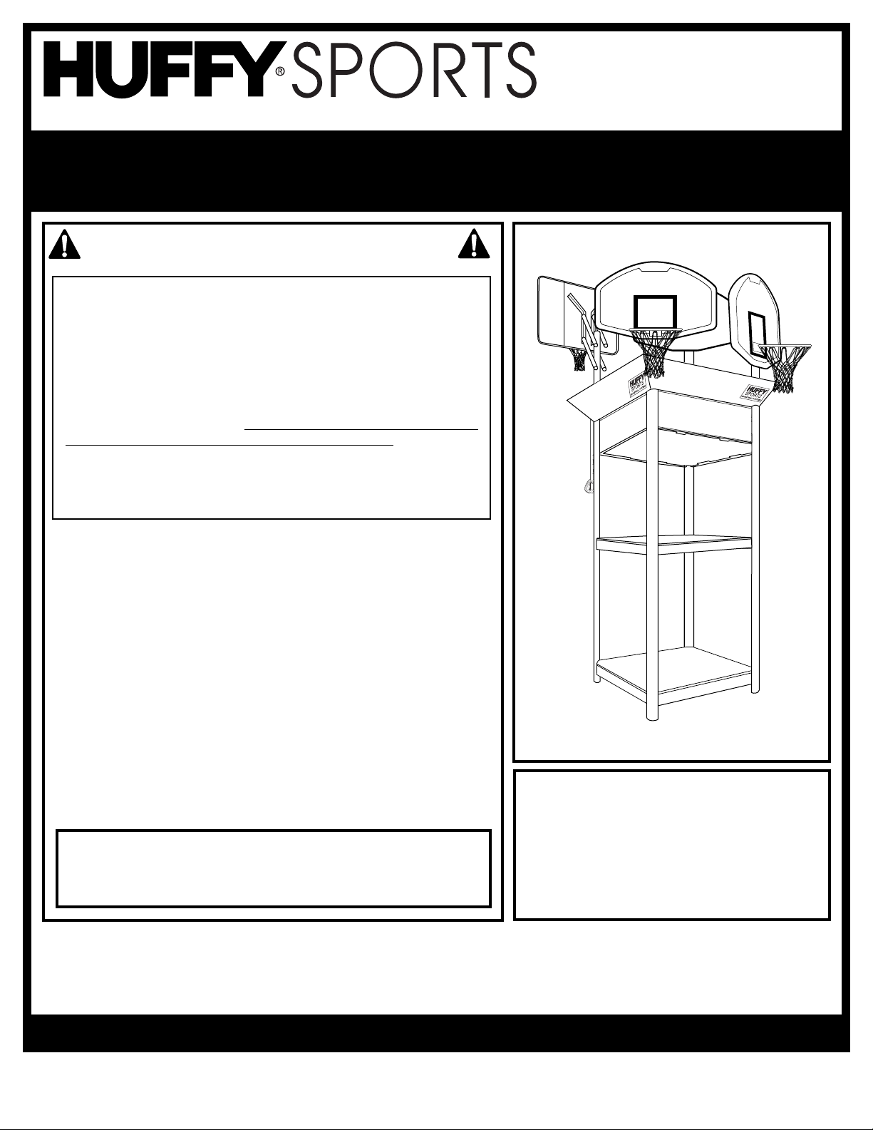
IMPORTANT!
We appreciate your purchasing one of our many fine products. We are sure that you will be very satisfied with your selection. Although
great care and effort have been taken, problems may occur. To ensure prompt and correct handling of any problems, or to answer any
questions, please contact the Sample and Display Technician at 414-820-3440.
REQUIRED TOOLS AND
MATERIALS:
• 2 People
• Wrenches: (Two each) 7/16”, 1/2”, 9/16”, and 3/4”
or Pliers
• Phillips Screwdriver
• 2 Step Ladders, 8 ft. (2.4 m)
Model 89025
Please refer to modular category #350 when arranging product for modular display.
SAFETY INSTRUCTIONS
FAILURE TO FOLLOW THESE SAFETY INSTRUCTIONS MAY
RESULT IN SERIOUS INJURY,
PROPERTY DAMAGE AND WILL VOID WARRANTY.
This unit is intended for display purposes only and
should not be used for play.
To ensure safety, do not attempt to assemble this system without
following the instructions carefully. Check entire box and inside all
packing material for parts. Before beginning assembly, read the
instructions and identify parts in this document. Proper and
complete assembly, use and supervision is essential for proper
operation and to reduce the risk of accident or injury. A high
probability of serious injury exists if this system is not installed,
maintained, and operated properly.
• During assembly, if using a ladder use extreme caution. Two
people are recommended for this operation.
• If technical assistance is required, contact Huffy Sports’ Sample
and Display Technician.
• Serious injury could occur if teeth/face come in contact with
backboard, net or rim.
• Display recommended for 3” (7.6 cm) or 3-1/2” (9 cm) Round or 4”
(10 cm) Square poles only.
• All instructions and warnings MUST accompany any display item
that is sold.
Most injuries are caused by misuse and/or not following
instructions.
Use caution when installing this unit.
Internet Address: http://www.huffysports.com
Page 2
P/N 211543B 06/03
2
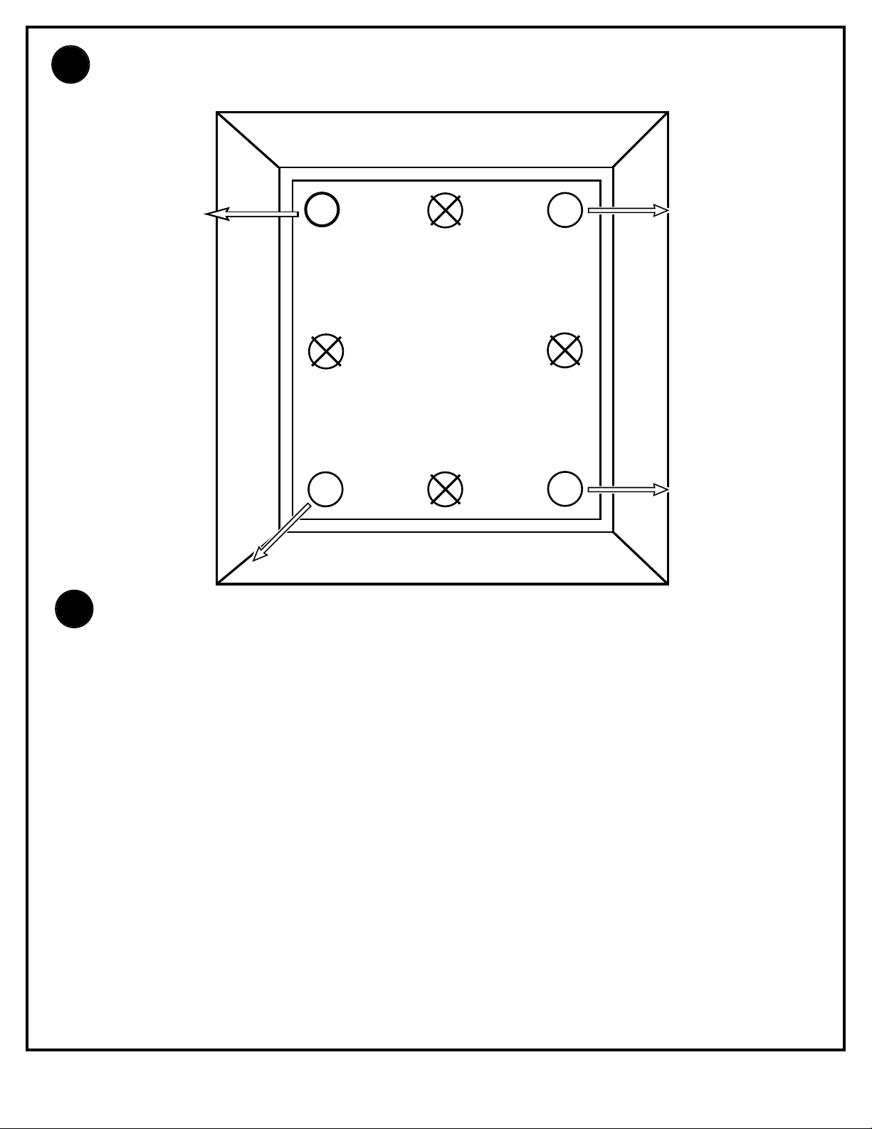
Install display boards in the marked locations. Each mounting location consists of a mounting pole
stub with the following dimensions: Height = 8”, O.D. = 3 3/8”, I.D. = 3 1/8” (arrows indicate
direction the board is facing).
Corner “2”
73603
Corner “4”
62959
Corner “3”
88603
Corner “1”
9H909A
Display boards will be mounted as follows:
Corner Location 1: 9H909A
• 44” SFA Board #909
• Hoop Time Logo
• Black Slam Jam Goal
• Exacta- Height Elevator System
Corner Location 2:73603
• 44” Fan Recycled Board
• Zone Attack Logo
• Black Slam Jam Goal
• Easyglide Elevator System
Corner Location 3: 88603
• 44” Fan Recycled Board
• Zone Attack Logo
• Black Standard Goal
• Exacta- Height Elevator System
Corner Location 4: 62959
• 40” Fan Recycled Board
• Street Heat Logo
• Black Standard Goal
• Extension Arm
Display Stand - Top View
1.
2.
Page 3
3
06/03 P/N 211543B
2
3
4
8
7
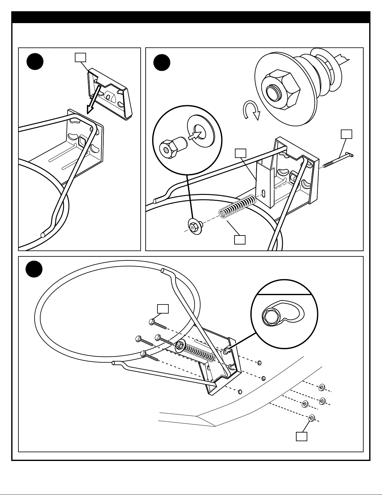
Assemble rims as shown below.
1
3.
5.
4.
RIM ASSEMBLY - Corner Locations 1 and 2
Page 4
P/N 211543B 06/03
4
6.
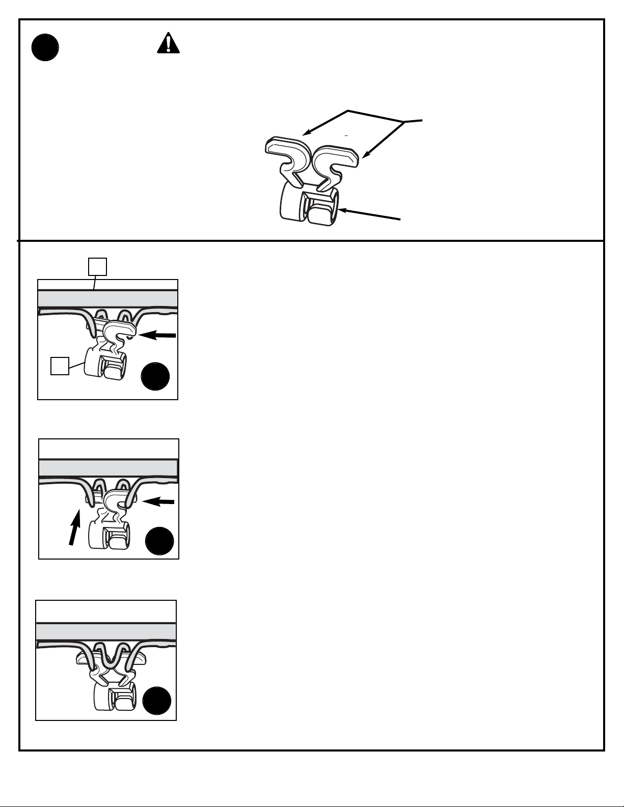
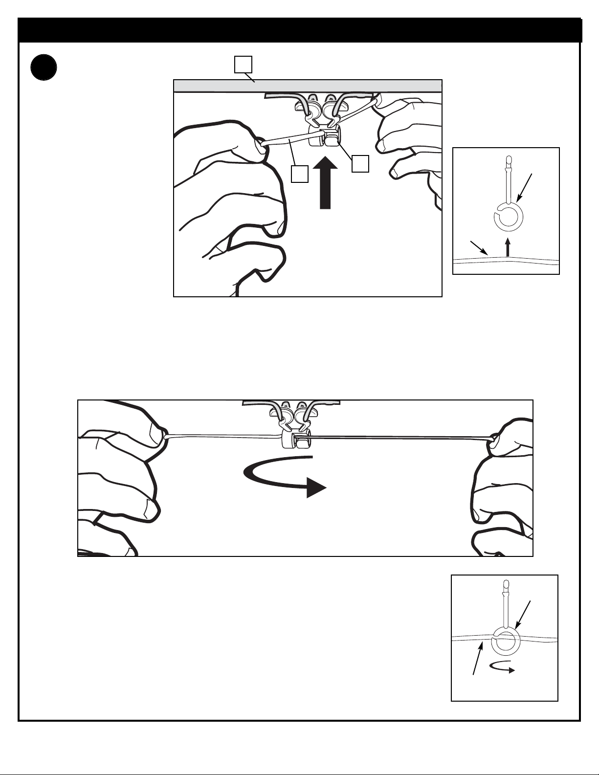
WARNING: Use of this product without proper installation of net
clips, or when all net clips are not present could result in bodily harm. Be
sure to follow directions carefully.
Install net clips.
CLIP “ARM”
CLIP “BODY”
Insert one “arm” of clip into ram as shown. Twist “body” of clip slightly so that second
“arm” slides over the top of the first “arm” as shown.
Push in direction indicated by arrows.
Push second “arm” back and into ram as shown.
Twist “body” of clip slightly again to spread “arms” of clip.
Clip “arms” must be flat and touching edge to edge as shown, not overlapping.
AA
BB
CC
58
9
Page 5
5
06/03 P/N 211543B
Insert net into bottom of clip as shown.
SIDE VIEW
Twist net until it snaps into position.
Net must be centered through clip.
NET
NETCLIP
SIDE VIEW
NET
NETCLIP
NET INSTALLATION
7.
58
9
10
Page 6
P/N 211543B 06/03
6
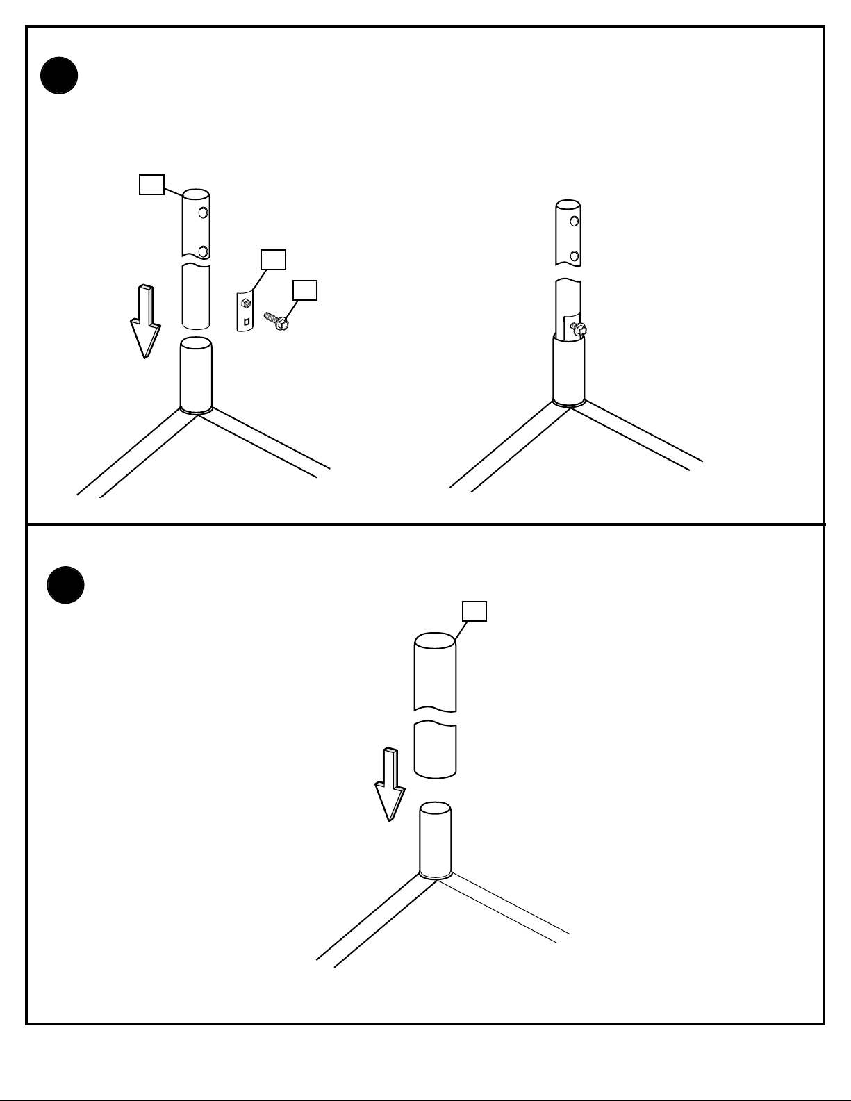
At corner locations 1, 2, and 3 install the display pole (11) to the mounting pole stub. If required, secure the
display pole (11), slide the display wedge (12) into position as shown. Tighten the set screw (13) to lock the
display pole (11) in place. Use the second wedge only if necessary to tighten the fit.
At corner location 4 slide the display pole (14) (3 1/2” diameter) over the mounting pole stubs.
12
13
14
11
8.
9.
Page 7
7
06/03 P/N 211543B
8
11
49
16
10.
11.
17
30
24
52
51
49
30
12.
49
8
55
54
54
57
44
57
55
13.
48
8
46
45
26
47
25
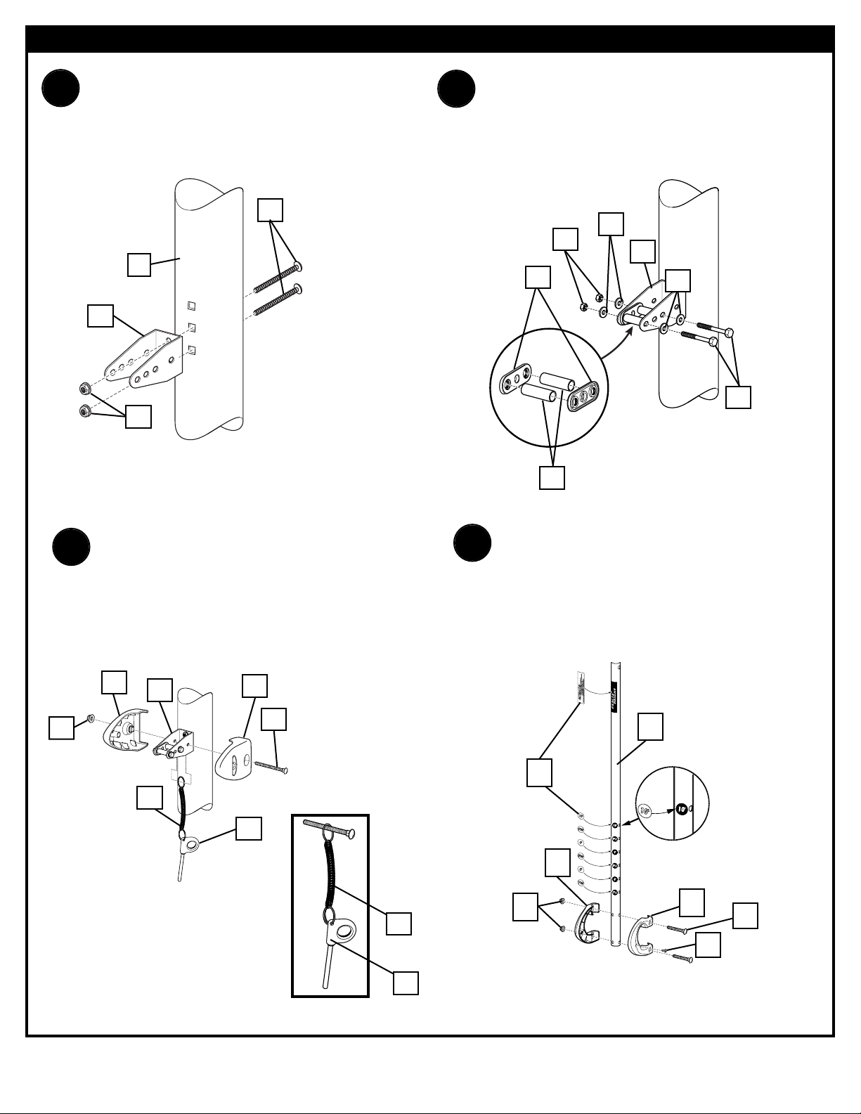
Install pole mount bracket (49) with
carriage bolts (16) as shown.
Tighten flange nuts (8) completely.
Attach spacers (51, 52) to pole mount bracket
(49) with bolts (24), washers (30), and nuts (17)
as shown. IMPORTANT! Tighten until
washers (30) no longer move.
Attach covers (54) onto pole mount bracket (49)
with carriage bolt (31) and nut (8) as shown.
IMPORTANT! Loop end of pin lanyard (57)
over carriage bolt (31) during this assembly.
NOTE: Assemble lanyard (57) to locking pin (55)
as shown.
Apply logo and height indicator labels (48) to
adjustment rod (47) as shown.
Attach handle parts (45, 46) to adjustment rod (47)
with screw (26), carriage bolts (22), and flange
nuts (8) as shown. NOTE: Holes in adjustment rod
allow for either rear access or side access.
ELEVATOR ASSEMBLY - Corner Locations 1 and 3
Page 8

P/N 211543B 06/03
8
37
14.
38
38
24
24
17
17
29
29
39
39
59
37
42
Refer To
Instructions
Included With Rim
Hardware For Rim
Assembly.
8
8
15.
59
27
Attach backboard support brackets (37) to the
backboard frame using bolts (24), spacers (38),
and nuts (17) as shown
.
Attach lower elevator tubes (29) to backboard support brackets (37) using spacers
(59), bolt (20), and nut (42) as shown. NOTE: Rim mounting nuts (8) and bolts
(39) supplied with rim hardware.
44” STEEL FRAME ACRYLIC BACKBOARD ASSEMBLY - Corner Location 1
Page 9

9
06/03 P/N 211543B
17.
16.
21
21
27
59
37
42
59
Attach upper elevator tubes (21) to backboard support
brackets (37) using spacers (59), bolt (27), and nut (42)
as shown.
Attach backboard assembly to pole section (11). Install
pole cap (43). NOTE: Two people are recommended for
this step. Use caution; elevator assembly is
heavy.
11
42
21
43
21
29
29
27
27
Page 10

P/N 211543B 06/03
10
19.
55
18.
Insert handle assembly through pole mount
assembly as shown. Lock pole assembly in place at
the 10’ (3.05m) mark with pin (55).
23
23
17
65
15
15
24
18
20.
44” FAN MOLDED PLASTIC BOARD ASSEMBLY - Corner Location 3
Attach adjustment rod (47) to lower elevator
tubes (29) using bolt (27) spacer (59) and
nut (42) as shown.
42
27
29
29
59
59
Assemble backboard brackets (23) using spacers (15) bolts (18, 24) and nuts (19, 17) as
shown.
47
Page 11

11
06/03 P/N 211543B
27
59
59
42
21.
29
29
23
8
8
29
REFER TO
INSTRUCTIONS
INCLUDED WITH RIM
HARDWARE FOR
RIM ASSEMBLY
23
22.
Attach lower elevator tubes (29) to backboard brackets (23) using spacers (59) bolt (27) and nut (42)
as shown.
Bend top of backboard brackets (23) outward to match up with holes on backboard and secure
using nuts (8) and bolts as shown. Attach rim to backboard using using bolts and nuts (8) as
shown.
Page 12

P/N 211543B 06/03
12
27
21
42
21
22
22
23.
42
21
21
27
27
29
42
43
24.
Attach backboard assembly to pole section (11).
Then install pole cap (43). NOTE: Two people
are recommended for this step. Use caution;
elevator assembly is heavy.
Attach upper elevator tubes (21) to backboard brackets (23) using spacers (22) bolt (27) and nut (42)
as shown.
Page 13

13
06/03 P/N 211543B
42
27
29
29
47
59
59
26.
Insert handle assembly through pole mount
assembly as shown. Lock pole assembly in
place at the 10’ (3.05m) mark with pin (55).
55
A
C
B
To Set Backboard Height:
A. While holding handle, remove pin (55).
B. Move elevator up or down to desired height.
C. Replace pin full length to lock system at desired
height.
55
25.
HEIGHT ADJUSTMENT
27.
Attach adjustment rod (47) to lower
elevator tubes (27) using bolt (27) spacer
(59) and nut (42) as shown.
Page 14

P/N 211543B 06/03
14
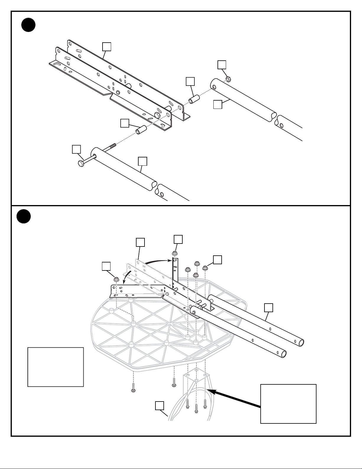
1.
Attach elevator bracket (36)
and reinforcement bracket (41)
to pole section (11) using bolts
(16) and nuts (8) as shown.
41
11
36
16
8
23
23
17
65
15
15
24
18
2.
44” FAN MOLDED PLASTIC BOARD ELEVATOR ASSEMBLY - Corner Location 2
Assemble backboard brackets (23) using spacers (15) bolts (18, 24) and nuts (19, 17) as
shown.
Page 15
15
06/03 P/N 211543B
Bend top of backboard brackets (23) outward to match up with holes on backboard and secure using
nuts (8) and bolts as shown. Attach rim to backboard using using bolts and nuts (8) as shown.
27
60
60
42
3.
29
29
23
8
58
8
8
29
4.
DO NOT USE
WASHERS HERE ON
SPRING RETURN
STYLE RIMS
REFER TO
INSTRUCTIONS
INCLUDED WITH RIM
HARDWARE FOR
RIM ASSEMBLY
23
Attach lower elevator tubes (29) to backboard brackets (23) using spacers (60) bolt (27) and nut (42) as
shown.
Page 16

P/N 211543B 06/03
16
20
21
42
21
56
56
5.
6.
Attach upper elevator tubes (21) to backboard brackets (23) using spacers (56) bolt (20) and nut (42)
as shown.
Attach backboard assembly to top pole section
(11). Then install pole cap (43). NOTE: Two
people are recommended for this step. Use
caution; elevator assembly is heavy.
42
21
21
20
27
29
42
43
Page 17

17
06/03 P/N 211543B
5
6
6
31
28
5
31
7.
Fig. A
Fig. B
6
Insert locking pin (28) into bracket on adjustment
tube (6). Insert cross pin (5) through hole in bracket
and locking pin (28) as shown in figure A. Fit left
handle (31) onto adjustment tube (6) so the bottom of
adjustment tube (6) sits on the two small ribs of the
handle as shown in figure B.
Page 18

P/N 211543B 06/03
18
28
6
31
53
28
50
31
53
8.
Fig. C
Insert spring (53) into back of locking pin (28) as shown. Spring (53) should rest between two
small ribs at the back of the plastic handle as shown in Figure C. Insert top of trigger (50) into
bracket on the adjustment tube (6) as shown. The plastic post of the handle pieces should go
through the hole in bottom of trigger (50) and hold it into place as shown.
Page 19

19
06/03 P/N 211543B
27
59
59
6
42
61
61
61
61
61
9.
10.
11.
64
63
36
62
62
6
29
Attach adjustment tube to lower elevator tubes
using bolt spacers and nut as shown.
Finish handle assembly by
attaching right handle using screws
as shown.
Insert lower adjustment rod (62) into bottom of adjustment tube (6), pull trigger to allow lower adjustment
rod to move about mid-way into adjustment tube (6), release the trigger so the lower adjustment rod (62)
locks into position midway inside the adjustment tube (6). Attach the lower adjustment rod (62) to
elevator bracket (65) using bolt (63) and nut (64) as shown.
TWO PERSON MINIMUM
REQUIRED FOR THIS
PROCEDURE.
NOT FOLLOWING
RECOMMENDATION MAY
RESULT IN BODILY INJURY.
WARNING
19
Page 20

P/N 211543B 06/03
20
TWO PERSON MINIMUM
REQUIRED FOR THIS
PROCEDURE.
NOT FOLLOWING
RECOMMENDATION MAY
RESULT IN BODILY INJURY.
WARNING
Assemble 40” fan backboard as shown below with a standard rim as shown.
40” FAN BACKBOARD ASSEMBLY - Corner Location 4.
35
32
33
8
7
7
35
12.
34
8
Page 21

21
06/03 P/N 211543B
Item #26 (2)
Item
Qty. Part No. Description
1 2 900033 Back Bracket
2 2 203796 T-Bolt, 3/8-16 x 5
3 2 200318 Bracket
4 2 203472 Spring
5 1 200215 Cross Pin
6 1 900006 Adjustment Tube - Upper
7 16* 203113 Bolt, Hex-Flange 5/16-18 x 2.5
8 34 203100 Nut, Hex-Flange 5/16-18 whiz Lock
9 48 201219 Clip, Smart Clips
10 4 204290 Net
11 3 904847 Pole, Display
12 2 206987 Wedge
13 2 203156 Bolt, Hex 5/16-18 x 1
14 1 908407 Pole, Display
15 4 201129 Spacer, 1 3/4
16 4 203053 Bolt, Carriage, 5/16-18 x 4 Long
17 8 201124 Lock Nut, Hex Head, 3/8-16
18 2 240017 Bolt, Hex Head 1/4-20 x 2 1/4
19 1 200210 Right Handle
20 2 206304 Bolt, Hex Head 1/2-13 x 6 5/16
21 4 908002 Elevator Tube, Black
22 4 206311 Spacer, Plastic
23 4 900846 Board Bracket, Black
24 2 206360 Bolt, Hex Head 3/8-16 x 2 5/8
25 4 203103 Carriage Bolt
26 2 204803 Screw Phillips Head
27 13 201640 Bolt, Hex Head 1/2-13 x 7-1/4
28 1 200214 Locking Pin
29 6 904821 Elevator Tube, Black, Long
30 8 203232 Washer, Flat
31 1 200211 Left Handle
32 1 201097 Extension Arm
33 24 203309 Washer 1” O.D.
34 4 200516 Cover, Bolt End
Item
Qty. Part No. Description
35 6 203218 Washer 5/16 Flat
36 1 200209 Pole Mount Bracket
37 2 900103 Bracket, Backboard Support
38 2 200874 Spacer, Steel .402 I.D.x.50 O.D.x1.5 Long
39 4* 205528 Bolt, Hex Flange, 5/16-18 x 1 Long
40 2 201642 Spacer .530 I.D. x.63 O.D. x .875 Long
41 1 206990 Reinforcement Bracket
42 15 206340 Lock Nut, Hex Head, 1/2-13
43 3 207103 Cap, Pole Top
44 1 203038 Bolt, Carriage 5/16-18 X 2-3/4
45 2 204855 Handle, Left
46 2 204856 Handle, Right
47 2 904866 Height Adjustment Rod
48 2 204872 Label, Height Indicator
49 2 204832 Bracket, Pole Mount
50 1 200212 Trigger
51 4 204857 Spacer, Metal 1/2” O.D.x1.44 Long
52 4 204858 Spacer, Biscuit, Plastic
53 1 200257 Compression Spring
54 4 204859 Cover, Pin Slide
55 2 204850 Pin, Locking
56 4 201642 Spacer, .530 x .625 Long
57 2 204853 Lanyard, Black
58 4 Rim
59 8 202862 Spacer,1.190 Long
60 2 201681 Spacer, .88 Long
61 5 204804 Screw, Phillips Head, 3/4 Long
62 2 908008 Adjustment Rod - Lower
63 1 202739 Bolt 5/16-18 x 1.75 Long
64 2 203220 Nylon Insert Lock Nut, 5/16-18
65 2 203493 Lockut,Hex,1/4-20
Item #6 (2)
* You May Have Extra Parts With This Model.
PARTS LIST - See Hardware Identifier
HARDWARE IDENTIFIER (NUTS & SCREWS)
HARDWARE IDENTIFIER (STEEL SPACERS)
Item #15 (4)
Item #42 (15)
Item #8 (34)
Item #17 (8)
Item #65 (2)
Item #38 (2)
Item #61 (5)
Page 22

P/N 211543B 06/03
22
Item #27 (13)
Item #18 (2)
Item #20 (2)
Item #33 (24)
Item #35 (6)
22 of 22
Item #30 (8)
Item #39 (4)*
Item #40 (2)
Item #59 (8)
Item #60 (2)
HARDWARE IDENTIFIER (BOLTS & SCREWS)
HARDWARE IDENTIFIER (SPRINGS & WASHERS)
Item #16 (4)
Item #22 (4)
Item #63 (1)
PLASTIC SPACERS
Item #24 (2)
Item #7 (16)
Item #2 (2)
Item #25 (4)
Item #4 (2)
 Loading...