

Page 1
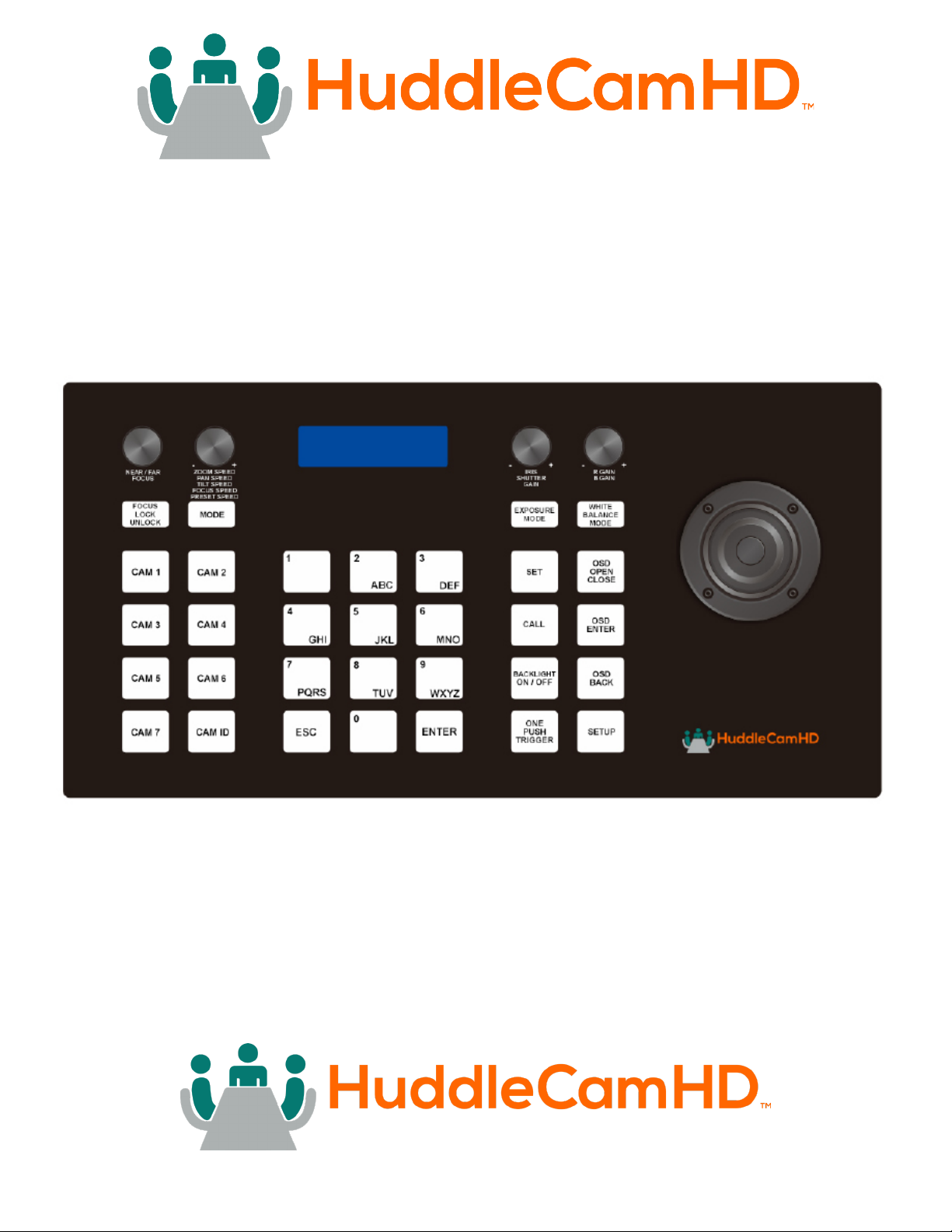
HuddleCamHD Serial Joystick Controller
Please check huddlecamhd.com for the most up to date version of this document.
152 Robbins Rd., Downingtown, PA 19335 USA | HuddleCamHD.com | 484-593-2247
©2023 | HuddleCamHD | All Rights Reserved
User Manual
Model No. HC-JOY-G4
V1.0
(English)
ver 1_1 rev 5-23
Page 2

Table of Contents
Preface .......................................................... 3
Precautions ................................................. 3
Warranty ................................................... 4
Supplied Accessories ......................................... 4
FCC Statement .............................................. 4
Physical Description ................................................ 5
Back View of the Joystick Controller .............................. 6
Key Product Features .......................................... 7
Key Technical Specications .................................... 7
Installation .................................................. 8
Hardware Features ............................................ 8
Control Mode ................................................ 8
Keyboard/Joystick Operation. . . . . . . . . . . . . . . . . . . . . . . . . . . . . . . . . . . . . . . . . . 9
Manual Control Options ........................................ 9
Selecting a Camera ........................................... 10
PTZ Presets ................................................. 10
Set a PTZ Preset ............................................. 10
Mode ...................................................... 11
Joystick Setup Menu - LCD Menu ................................ 11
Keyboard/Joystick Connection Wiring and Indicators ....................... 12
Troubleshooting .................................................... 14
2
ver 1_1 rev 5-23
Page 3

Preface
Congratulations on receiving your new HuddleCamHD Serial Joystick Controller. This manual
introduces the function, installation, and operation of the Joystick. Prior to installation and usage,
please read the manual thoroughly.
Precautions
To avoid any damage to the unit, please take these precautions when using your HC-JOY-G4 Joystick
Controller.
• Please read this manual carefully before using the joystick.
• Avoid damage from stress, violent vibration or liquid intrusion during transportation, storage or
installation.
• Do not apply excessive voltage. (Use only the specied voltage.) Otherwise, you may
experience electrical shock.
• Keep the joystick controller away from strong electromagnetic sources.
• Do not clean the joystick controller with any active chemicals or corrosive detergents.
• Do not disassemble the joystick controller or any of the joystick’s components. If problems arise,
please contact your authorized dealer.
• After long term operation, moving components can wear down. Contact your authorized dealer
for repair.
3
ver 1_1 rev 5-23
Page 4
Warranty
HuddleCamHD includes a limited parts & labor warranty for all HuddleCamHD manufactured
joystick controllers. The warranty is valid only if HuddleCamHD receives proper notice of such defects
during the warranty period. HuddleCamHD, at its option, will repair or replace products that prove to
be defective. HuddleCamHD manufacturers its hardware products from parts and components that
are new or equivalent to new in accordance with industry standard practices.
Supplied Accessories
When you unpack your joystick controler, make sure that all
the supplied accessories are included:
• Joystick Controller 1
• RS-232 Cable 1
• 12V DC Power Supply 1
• Quick Start Guide 1
Note: The included RS-232 cable is used to connect the joystick the rst
camera. If the rst camera is located further than the cable, a DB9 extender
should be used. Subsequent 2nd, 3rd and 4th cameras are connected
using the in and out 8-pin mini-din connections using cascade cables. You
can learn more at PTZOptics.com/cables.
FCC Statement
This equipment has been tested and found to comply with the limits for a Class B digital device,
pursuant to part 15 of the FCC Rules. These limits are designed to provide reasonable protection
against harmful interference when the equipment is operated in a commercial environment. This
equipment generates, uses, and can radiate radiofrequency energy and, if not installed and used in
accordance with the instruction manual, may cause harmful interference to radio communications.
FCC Caution: Any changes or modications not expressly approved by the party responsible for
compliance could void the user’s authority to operate this equipment. Operation is subject to the
following two conditions: This device may not cause harmful interference, and (2) this device must
accept any interference received, including interference that may cause undesired operation.
• Warning - This is a class B product. In a domestic environment, this product may cause
radio interference in which case the user may be required to take adequate measures.
Copyright Notice
The entire contents of this manual / guide, whose copyright belongs to HuddleCamHD, may not be cloned, copied, or translated in any
way without the explicit permission of the company. The product specications referred to in this document are for reference only and
as such are subject to updating at any time without prior notice.
©2023 | HuddleCamHD | All Rights Reserved
4
ver 1_1 rev 5-23
Page 5
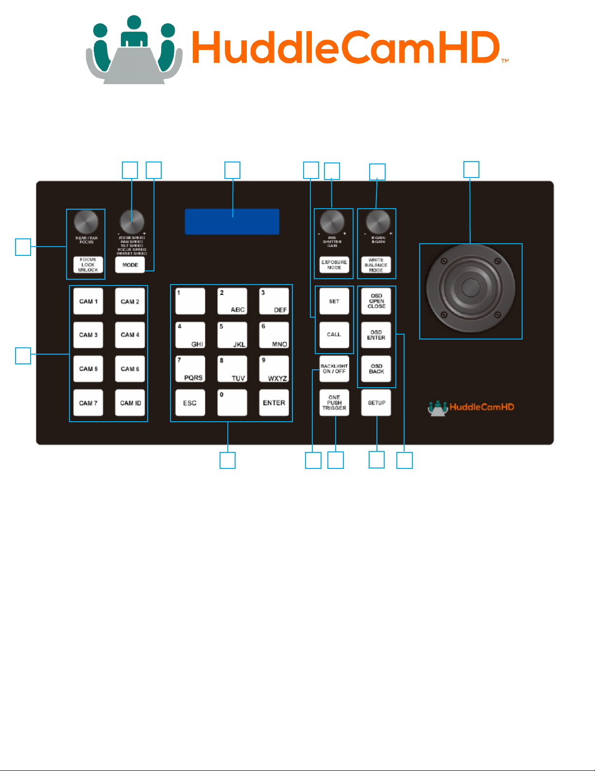
Physical Description
1
2 4
3
5 6
7
8
9
10 11
12
13
14
1. Speed Control Dial 8. Focus Control
Adjust Control Speeds Adjust or Lock Focus
2. Mode Change Button 9. Camera Select
Basic & Matrix Modes Select your camera
3. LCD Display 10. Numeric Buttons
Displays Connection Info Used for Presets
4. Set & Call Presets 11. Backlight Toggle
Set and/or Call Preset Increase Backlight
5. Exposure Control 12. OnePush Trigger
Exp Modes & Settings Calculate white level
6. White Balance Control 13. Joystick Setup Menu
WB Modes & Settings Enter Joystick Menu
7. Joystick Controller 14. Camera OSD
Pan, Tilt & Zoom Adjust camera settings
5
ver 1_1 rev 5-23
Page 6
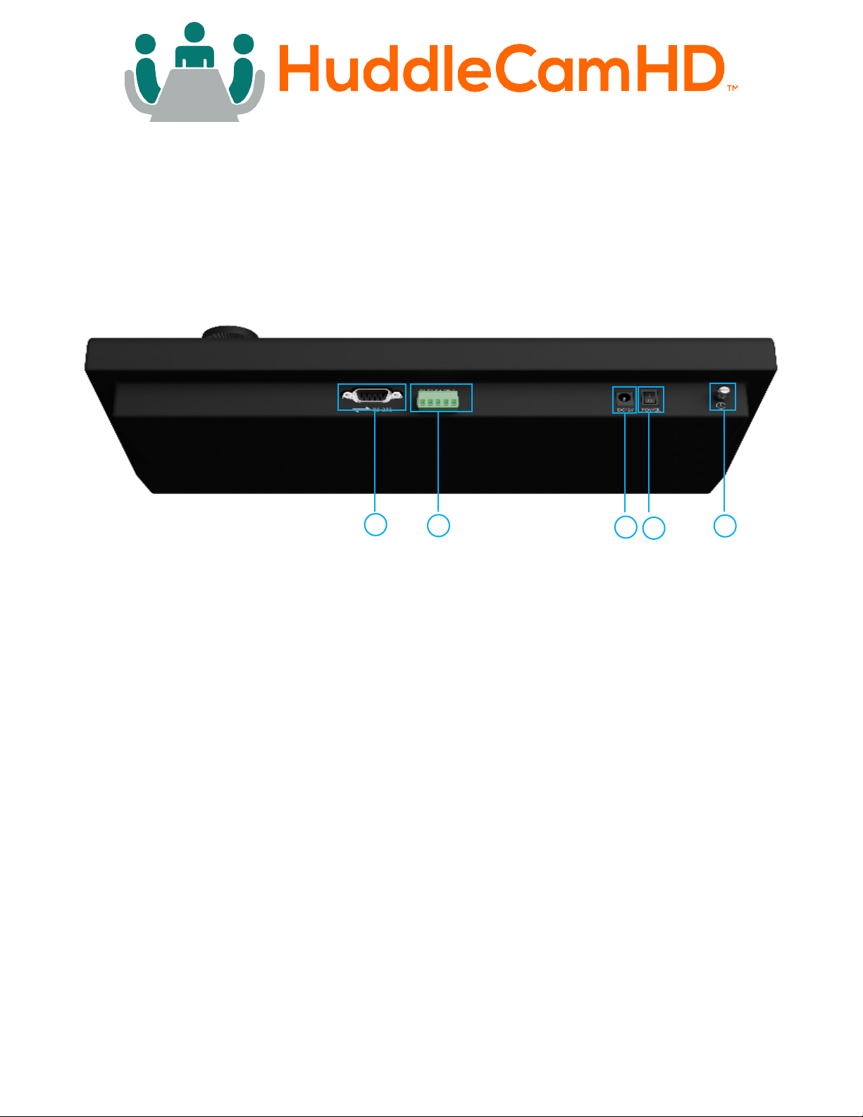
Back View of the Joystick Controller
1. RS-232 Port (DB9 connection)
2. RS-422 / RS-485 Port
3. 12V DC Power Port
4. Power Switch
5. Grounding Knob
1
2
3
4
5
6
ver 1_1 rev 5-23
Page 7

Key Product Features
• All Metal housing
• VISCA, PELCO-D and PELCO-P protocol support
• Key-press “BEEP” conrmation (optional – set on or o)
• Variable speed control of pan, tilt, zoom, focus, and presets
• Auto/Manual Focus and Iris
• Cameras #1 -7 Quick Select buttons
• Quick preset set & call (0 – 9)
• Set and Call up to 255 presets per camera
• Real time display of the current status
• 2 Year Warranty
Key Technical Specifications
• Control Interfaces
• RS232 full-duplex, RS485 semi duplex, RS422 full-duplex
• Variable Baud Rate 1200 to 19200 bps
• Maximum communication distance: RS485: 3,937ft [1200m] using 24 gauge twisted pair
cabling
• Can control a maximum 255 cameras via Pelco-D/P
• Voltage: 12VDC
• Power Consumption: 6W Max
• Display: LCD
• Working Temperature: 14°F ~ 122°F [-10° ~ +50° C]
• Working Humidity: 10 ~ 90% (non-condensation)
• Weight 3.4 lbs. [1.6 kg]
• Dimensions: 12.6”(W) x 7.1”(D) x 4.3”(H) [320mm x 181mm x 110mm]
7
ver 1_1 rev 5-23
Page 8

Installation
• Power Supply Interface (5.5mm x 12mm center pin JEITA style jack):
12VDC / 2000mA power supply
• RS485/422 interface (5p screw terminal):
Ŝ 1:485+/422TxA
Ŝ 2:485-/422TxB
Ŝ 3:422RxA
Ŝ 4:422RxB
Ŝ 5:485/422Gnd
• RS232 interface (DB9M port): 2:Rx, 3:Tx, 5:Gnd
Hardware Features
• Keys: momentary push buttons (keys)
• Joystick: 3-axis joystick
• Digital display: LCD display
Control Mode
• VISCA, PELCO-P and PELCO-D protocol support
• Control interfaces:
Ŝ 5p Screw Terminal (RS485/RS422)
Ŝ DB9 (RS232)
• Baud rate: 1200, 2400, 4800, 9600, 19200
• Parameters: 8 bits, 1 stop bit, No parity
8
ver 1_1 rev 5-23
Page 9

Keyboard/Joystick Operation
Basic Control
• Pan & Tilt Control
Ŝ Joystick movement provides variable speed pan and tilt of the camera head.
• Zoom Control
Ŝ Rotation of the joystick controls variable speed zoom of the lens.
▪ Clockwise rotation of the joystick = zoom in.
▪ Counter-clockwise rotation of the joystick = zoom out.
Manual Control Options
• Focus Control – VISCA Protocol only. Pelco-D & P do not support Manual Focus
commands.
Ŝ You can adjust the focus level by twisting the Focus knob. Manual Focus is
automatically enabled once the knob is twisted.
▪ Twist the knob clockwise to Focus Far, and counter-clockwise to Focus Near.
Ŝ You can return to Auto Focus mode by pressing in the Focus knob.
• Exposure Control – VISCA Protocol only. Pelco-D & P do not support Manual Exposure
commands.
Ŝ The Iris / Shutter / Gain knob allows you to adjust the corresponding Exposure
settings. Press the knob in to change your selection.
Ŝ Note: Some cameras do not have an “Iris” or “Shutter” mode. Use Manual Exposure
mode for best results.
• White Balance Control - VISCA Protocol only. Pelco-D & P do not support Manual White
Balance commands.
Ŝ The R Gain / B Gain knob allows you to adjust the corresponding Red or Blue Gain
level. Press the knob in to change your selection.
Ŝ Note: Your camera must be set to Manual White Balance mode in order to manually
dene the Red and Blue Gain levels.
• Speed Control
Ŝ You can adjust the Pan, Tilt, Zoom, Focus, and Preset control speeds by twisting the
Speed knob. Press the knob in to change your selection.
Ŝ You can adjust the Pan (0 – 24), Tilt (0 - 20), Zoom (1 - 7), Focus (1 - 7), and Preset
Speed (1 - 24).
9
ver 1_1 rev 5-23
Page 10

Selecting a Camera
Quick Camera Select
1. Press the CAM # button associated with the camera you want to control.
CAM ID Button
1. Press the CAM ID Button
2. Input the Camera ID you want to control.
3. Press the Enter button
PTZ Presets
Set a PTZ Preset
• Quick Preset Set
1. Press and hold one of the 0 - 9 buttons for 3+ seconds to Set a preset in the current
position.
Set Button
1. Press the “Set” button
2. Input the Preset number you want to Set
3. Press the “Enter” button to save the preset.
Call a PTZ Preset
1. Quickly press one of the 0 - 9 buttons to Call that preset.
Call Button
1. Press the “Call” button
2. Input the Preset number you want to Call
3. Press the “Enter” button to call the preset.
Notes on using presets with VISCA:
For your convenience, the HC-JOY-G4 uses the same presets as the IR remote controller, VISCA,
Pelco-D, or Pelco-P protocols. This is in contrast to Sony’s traditional oset of 1 between the IR
remote and VISCA commands.
10
ver 1_1 rev 5-23
Page 11

Mode
The modes cycle through sequentially. To select a control mode, press the “Modes” button until the desired
mode is selected. You can return to standard camera control by selecting “Basic Mode O”.
• No Mode selected: All of the joystick’s functionality behaves as expected.
• Basic (PTZ Disabled): Most of the joystick’s functionality is disabled. The user is only capable
of selecting a camera to control, and calling presets on that camera.
• Basic (PTZ Enabled): Most of the joystick’s functionality is disabled. The user is only capable of
selecting a camera to control, calling presets on the camera, and moving it with the joystick.
• Matrix Mode: Most of the joystick’s functionality is disabled. The only thing the user can perform
is calling the rst 3 presets on cameras 1, 2, & 3.
Ŝ On the alphanumeric buttons:
▪ Buttons 1 - 3 call presets 1 - 3 on camera 1.
▪ Buttons 4 - 6 call presets 1 - 3 on camera 2.
▪ Buttons 7 - 9 call presets 1 - 3 on camera 3.
Joystick Setup Menu - LCD Menu
Key Tone
• Options include: On, O
Restore Default
• You must press Enter twice to restore the default settings. Press the Escape button to
cancel.
ADD:
• Options include: VISCA, Pelco-D, Pelco-P
• To add a camera to the joystick, you will need to select the desired control protocol then
press the Enter button. Use the joystick to select the camera ID.
Ŝ Left and Right move in increments of 1.
Ŝ Up and Down move in increments of 5.
Version
• Displays the rmware version
Invert Pan
• Options include On, O
Invert Tilt
• Options include On, O
11
ver 1_1 rev 5-23
Page 12
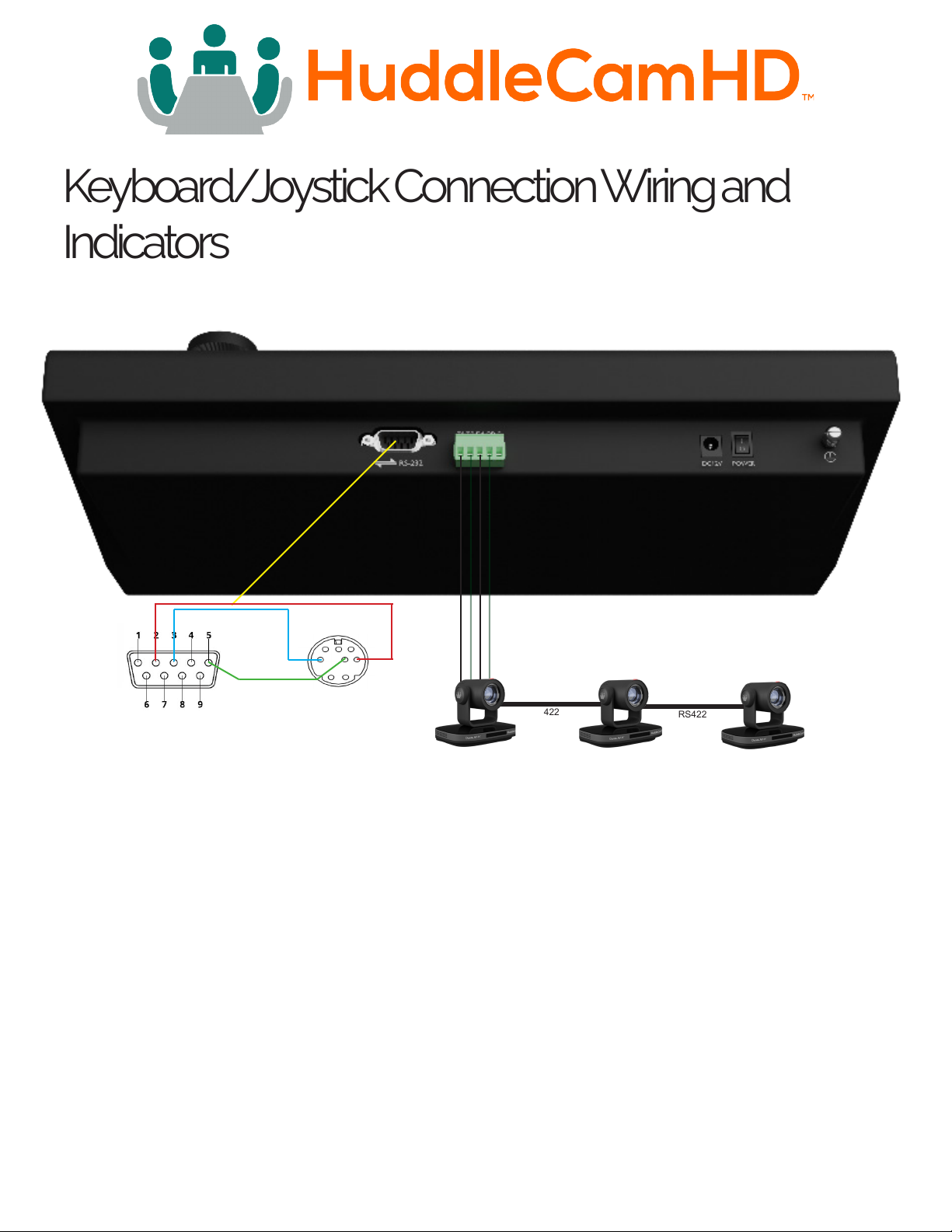
Keyboard/Joystick Connection Wiring and Indicators
RS-232 DB9
Camera
Mini DIN
Joystick
RS422
RS422
Power:
• Joystick requires external 12VDC. Use only the 12VDC power supply shipped with the unit.
The Joystick may be connected to cameras via RS-232, RS-485 or RS-422.
• For RS-232, connect the DB9 port of the joystick to the miniDin8 (VISCA) port of the
camera with pin-out as follows:
Ŝ KB Tx – Pin 3 ............... Camera Rx - Pin 5
Ŝ KB Rx – Pin 2 .............. Camera Tx - Pin 3
Ŝ KB Gnd – Pin 5 ............ Camera Gnd - Pin 4
When connecting multiple cameras,the rst cable in a serial control chain is a DB9 to 8-pin mini-din
cable as seen in Fig. 1 (included). The 2nd, 3rd, and 4th cameras are connected using an 8-pin minidin cascade cable as seen in Fig. 2 (not included). See Fig. 3.
12
ver 1_1 rev 5-23
Page 13
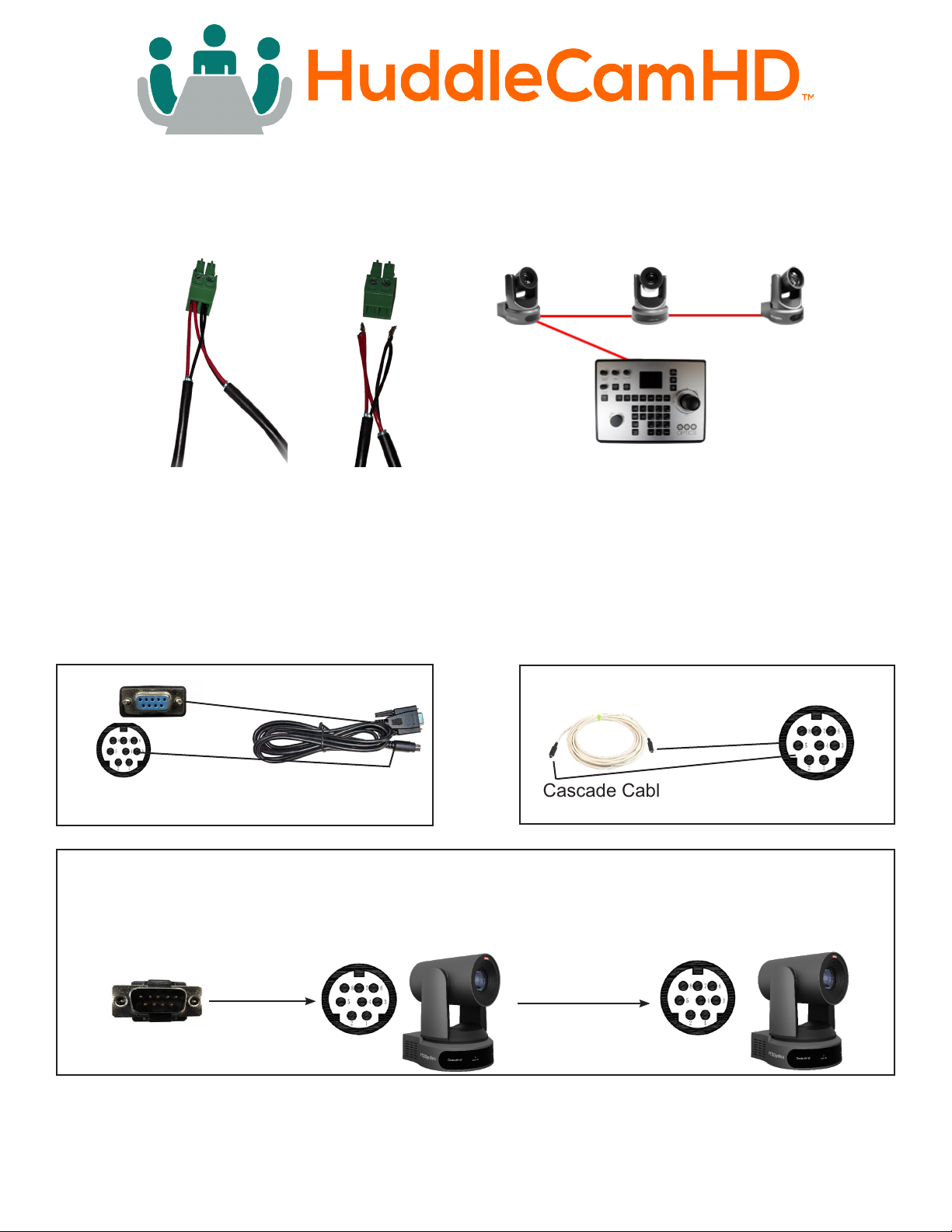
• For RS-485, connect the 5p screw terminal port of the joystick to the RS-485 port of the
camera with pin-out as follows:
Ŝ KB Ta – Pin 1---------- Camera (+)
Ŝ KB Tb – Pin 2---------- Camera (-)
Ŝ KB Gnd – Pin 5---------- Camera (G) (if present – some cameras will not require a G)
Daisy-Chain Connection Guide
• For RS-422, connect the 5p screw terminal port of the joystick to the RS-422 port of the
camera with pin-out as follows:
Ŝ KB Ta – Pin 1 ............... Camera (Rx-)
Ŝ KB Tb – Pin 2 ............... Camera (Rx+)
Ŝ KB Ra – Pin 3 .............. Camera (Tx-)
Ŝ KB Rb – Pin 4 .............. Camera (Tx+)
Ŝ KB Gnd – Pin 5 ............ Camera (G) (if present – some cameras will not require a G)
Fig. 2
8-pin mini DIN
RS-232 DB9
Connection
Fig. 1
DB9 Cable
(included)
Cascade Cable
(not included)
Fig. 3
RS-232 8 -pin Mini Din
RS-232 DB9 Male
Connection on Joystick
female Connection on
camera 1
8-pin mini DIN
Connection on cameras
2,3,4 +
Mini DIN
DB9 Cable
Cable
The DB9 cable that is included with the joystick is DB9 F on one end and mini DIN on the other. All
of the connections above are OUT of the camera (8-pin mini DIN), and IN to the next camera (also
8-pin mini DIN).
13
ver 1_1 rev 5-23
Page 14

Troubleshooting
• Cannot Control Camera at all
Ŝ Check that LCD is in the Main Menu. Press “Esc” key to return to main menu, if
needed. Note: Repeated presses may be required depending on how deep you are
in a menu, e.g. this can often happen after setting presets and then attempting to
Call presets without exiting the Set menu.
Ŝ Check both KB settings and camera settings to ensure that the following ALL match:
▪ Camera ID (e.g. 01, 02, etc…)
▪ Camera Protocol (e.g. VISCA, PELCO-P, PELCO-D)
▪ Baud Rate (e.g. 9600)
Ŝ Check all KB-camera connections and cabling per “Connection Wiring and
Indicators” section above.
• Controlling more than 1 camera at a time.
▪ Check all cameras to ensure that each has a unique ID.
▪ Check all camera settings in KB menu to make sure that the protocol setting for
that camera ID matches that of the actual camera.
Ͻ Note, you cannot typically mix VISCA, Pelco-P or Pelco-D cameras in the
same daisy chain.
▪ Check control wiring.
Ͻ For RS232, cabling must ow from KB into the VISCA-in port of the rst
camera and then from VISCA-out port of rst camera to VISCA-in port of
next camera, etc... A VISCA cross-over cable must be used for all camera
to camera connections. These are available from HuddleCamHD in various
lengths as well as from other sources.
Ͻ For RS485 and RS422, all connections are in parallel (e.g. all cams’ 485+
are connected to KB’s 485+ and all cams’ 485- are connected to KB’s 485-)
and termination may be required depending upon overall cabling distances
involved.
14
ver 1_1 rev 5-23
 Loading...