

HuddleCamHD 3X, HC3X-WH-G2, HC3X-BK-G2, HC3X-SV-G2, 10x-720 Installation & Operating Instructions Manual
HuddleCamHD 3x
USB 2.0 PTZ CAMERA
INSTALLATION & OPERATION MANUAL

Precautions………………………………………………………………………………………….
Safety Tips…………………………………………………………………………………………….
Please read this manual carefully before using the camera.
Avoid damage from stress, violent vibration or liquid intrusion during
transportation, storage or installation.
Take care of the camera during installation to prevent damage to the camera
case, ports, lens or PTZ mechanism.
Do not apply excessive voltage. (Use only the specified voltage.) Otherwise, you
may experience electrical shock.
Keep the camera away from strong electromagnetic sources.
Do not aim the camera at bright light sources (e.g. bright lights, the sun, etc.) for
extended periods of time.
Do not clean the camera with any active chemicals or corrosive detergents.
Do not disassemble the camera or any of the camera's components. If problems
arise, please contact your authorized dealer.
After long term operation, moving components can wear down. Contact your
authorized dealer for repair.
In the Box………………………………………………………………………………………….
Supplied Equipment…………………………………………………………………………….
3x Zoom USB 2.0 HD Video Conference Camera (1)
12V/2.0A DC Power Adapter (1)
Tripod Mounting System (1)
USB 2.0 A-A cable (3m)
RS-232C Serial Control cable
RS-232C to RS-485 adaptor cable
IR Remote Controller
User Manual (1)
Ver 1.2 7/15
Physical Description…………………………………………………………………………
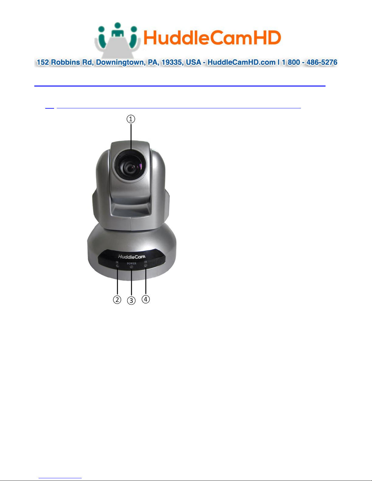
1. Front View…………………………………………………………………………………….
1. Lens
2. IR Receiver
To receive IR remote controller signal.
3. Power LED
Blue LED lights when unit is powered, LED is dark for Stand-By status.
4. IR Receiver
To receive IR remote controller signal.
Ver 1.2 7/15
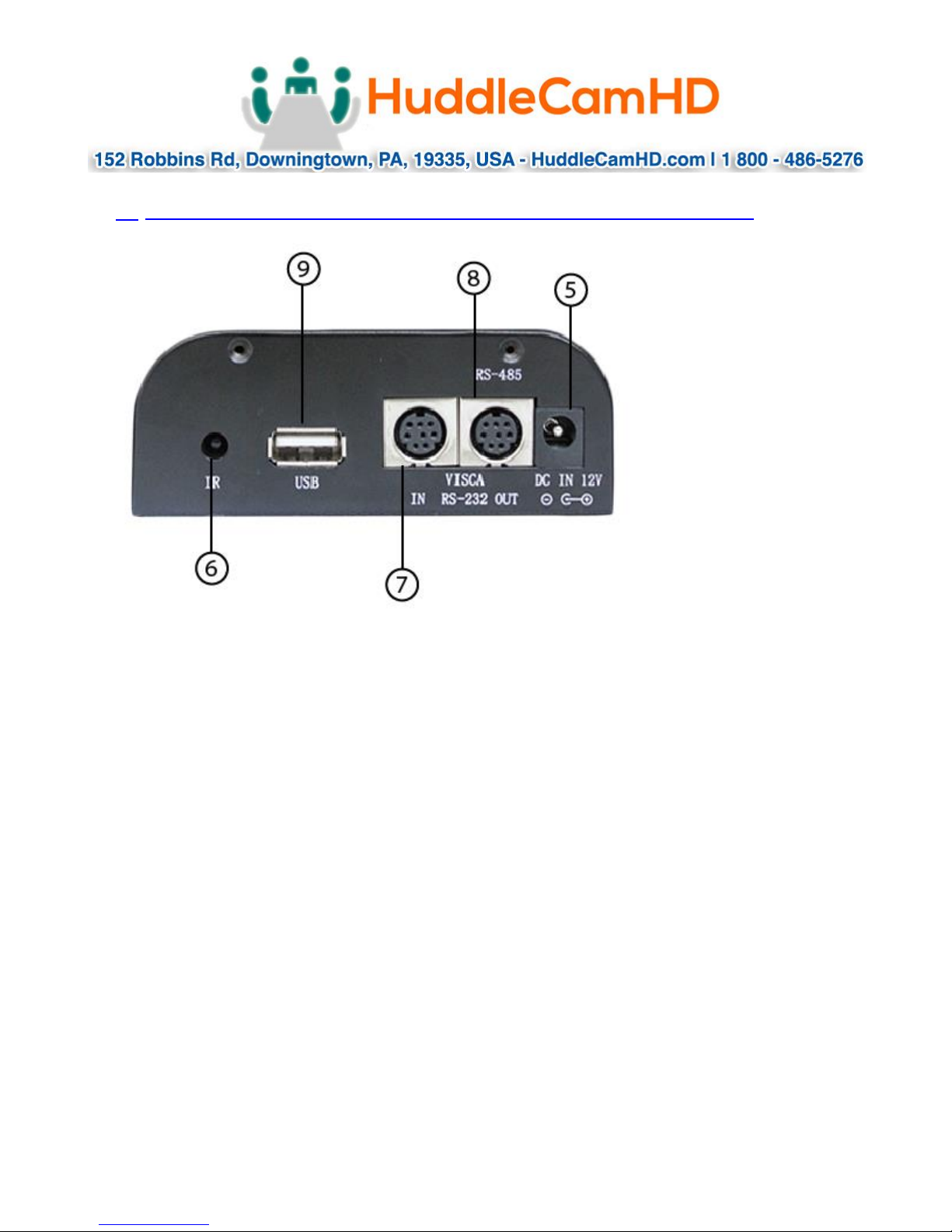
2. Rear View……………………………………………………………………………………
5. DC IN 12V Socket
Only use the Power Adapter supplied with this camera.
6. IR Receiver
To receive IR remote controller signals.
7. VISCA IN Port
For hard wired remote control from a 3
8. VISCA Out Port/RS485
Used for daisy chaining multiple cameras for RS-232 RS-485 control.
9. USB 2.0 Interface
For connection to PC (USB 2.0 port. Will also function in a USB 3.0 port as USB 2.0
device).
rd
party PC, joystick, etc...
Ver 1.2 7/15
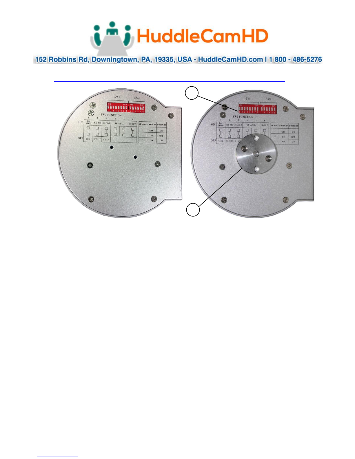
3. Bottom View…………………………………………………………………………………
1. Tripod
Will accept 1/4-20 bolt from 3rd party tripod, wall or ceiling mount using
included tripod adapter.
2. Dip-Switches
Used for selecting serial and IR communications settings.
Ver 1.2 7/15
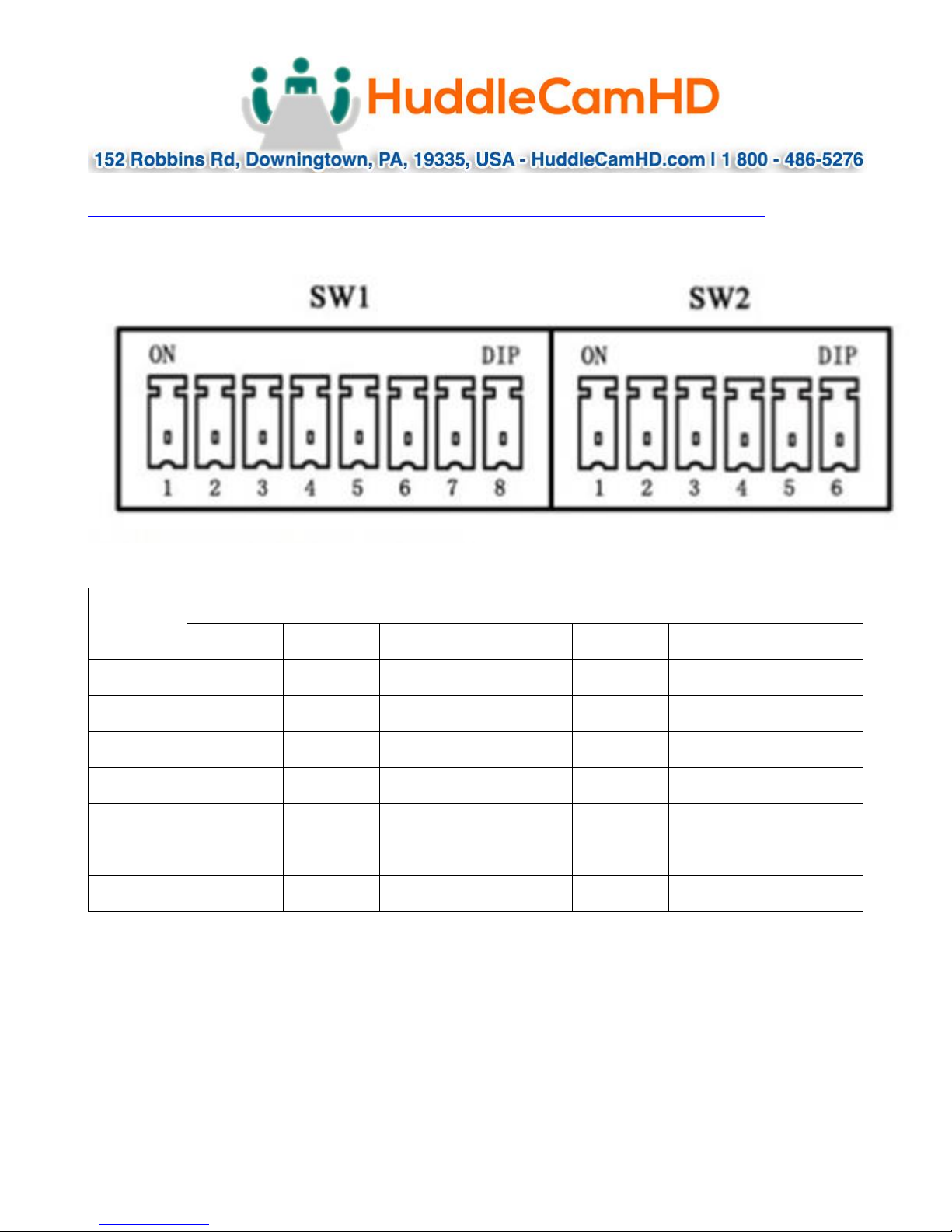
Address
SW1 Switch State 1-7, (8 for stand-by)
DIP-1
DIP-2
DIP-3
DIP-4
DIP-5
DIP-6
DIP-7
1
ON
OFF
OFF
OFF
OFF
OFF
OFF
2
OFF
ON
OFF
OFF
OFF
OFF
OFF
3
OFF
OFF
ON
OFF
OFF
OFF
OFF
4
OFF
OFF
OFF
ON
OFF
OFF
OFF
5
OFF
OFF
OFF
OFF
ON
OFF
OFF
6
OFF
OFF
OFF
OFF
OFF
ON
OFF
7
OFF
OFF
OFF
OFF
OFF
OFF
ON
4. Dip-Switch Settings……………………………………………………………………………
Note: When changing Dip-Switch settings, make all changes with camera powered off.
SW1: Used for setting RS232 address.
Notes:
1. Broadcast address: If the Joystick is 255 (all dip switches on), any Camera can be
controlled by any address.
2. Test Address: If the dome camera address is 0 (all dip switches off), any address
code can control the dome camera.
Ver 1.2 7/15
 Loading...