

HuddleCamHD HD Color Video, D820-U30-SN6300/K3 Camera User Manual
1 / 26
HD Color Video Camera
User’s Manual
V 4.5(ENGLISH VERSION)
Please read this Manual before set up Camera,
and stick to its requirements strictly for Safety reason.
Suggest you save this manual for further inquires reference.

2 / 26
Precautions
Safety Tips
Please read this manual carefully before use the Camera.
To avoid damage from stress, violent vibration, soaking during
transportation, storage and installation.
Take care of each components of Camera during installation, and install
camera at where is affordable enough, to avoid drop or scratches of camera
case.
Do not apply excessive voltage. (Use only the specified voltage.) Otherwise,
you may get an electric shock or a fire may occur.
Keep the transmission of RS-485, Video signal away from powerful
electromagnetic radiation resources.
Do not shoot images that are extremely bright (e.g., light sources, the sun,
etc.) for long periods of time. Do not use or store the camera in the
specified extreme conditions. (Please refer to specification sheet of
camera.)
Do not clean camera with active chemical or corrosive detergents, and
remove dust or dirt on the surface of the lens with a blower (Commercially
available)
Do not disassemble any camera components, in case of abnormal operation,
contact your authorized dealer or the store where you purchased the
product.
After long time operation, these components may get machine wear like
Motor, slip ring, you can contact for repair or change, the local dealer or the
shop where you bought this camera.

3 / 26
Supplied Accessories
HD Color Video Camera (1)
12V/2.0A DC Power adaptor (1)
Installation bracket (1) Installation screw (1)
USB3.0 data lines (3m)serial control lineRS-232C to RS-485 cable
IR Remote Controller (1)
User’s Manual (1)
Main Features
Camera and Lens
Video CMOS Sensor: 1/2.8" Type Exmor CMOS 3.27 Megapixel
Image: 16:9 3.27 pixel
Video Signal:
60Hz mode, camera output 1080p30 as default, support 1080p@30/25/20/15/10/5,
720p, 800x600, 640x480/60/50/30/25/20/15/10/5;
50Hz mode, camera output 1080p@25 as default, support 1080p@25/20/15/10/5, 720p,
800x600, 640x480/50/25/20/15/10/5;
Lens zoom: 20 Optical x 12 digital zoom, f=4.7-90mm F1.6-3.5
Wide angle lens: 55.4 degree
Minimum Illumination: 0.1Lux
White Balance: Auto/Sunlight/Cloudiness/Shade/fluorescence white balance
Focus: Auto/Manual
Iris: Auto/Manual
Shutter Speed: 1/1 - 1/10,000S
Black light compensation: On/Off
Pan/Tilt Movement
Pan Movement: 0-355°
Tilt Rotation: Up: 45°, Down: 45°
Built in Pan/Tilt Motor: Pan Speed: 1-200°/Second Tilt speed: 1-150°/Second
Preset Speed: Pan running: 120°/sec Tilt running: 100°/sec

4 / 26
Preset: 64 preset position, 4 Patrol lines
Rear board connectors
High Definition Interface: USB 3.0
Controller Signal Interface: 8 leads mini DIN (VISCA IN, VISCA OUT/RS485)
Controller Signal Interface: Dip-switch Pin 7/TTL Signal;
Baud Ratio:
9600/ 38400 bps
Power supply interface: DC 12V 2A
Electrical Index
Power supply adapter: 12V DC/2A
Input voltage: 12V DC(10.5-14V DC)
Input power: 24W(MAX)
Structure
Material: All-alloy, PC plastic
Dimension (Width x highness x depth) :
154x250x140mm / 330x210x230mm (NET/PACKAGE)
Working environment: Indoor
Temperature: -0 to +45
Storage temperature: -10 to +60
Color: Silver Gray
5 / 26
Rear Board & function
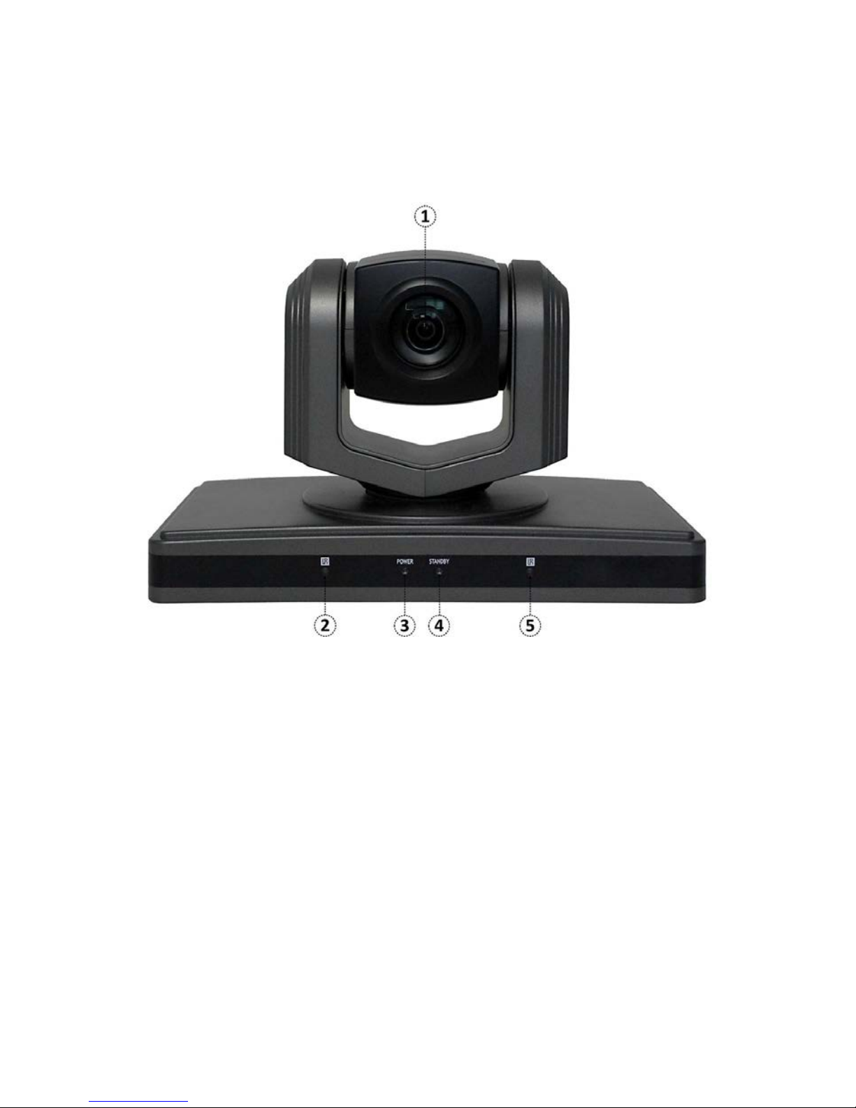
1Front View
Lens
Adopted 10x optical auto focus lens
IR Receiver
To receive IR mote controller signal LED
Power LED
LED Blinking when power plug in, Blue color Led
Stand by LED
LED blinking while shut down camera use remote controller, and Orange color
IR Receiver
To receive IR mote controller signal LED
6 / 26
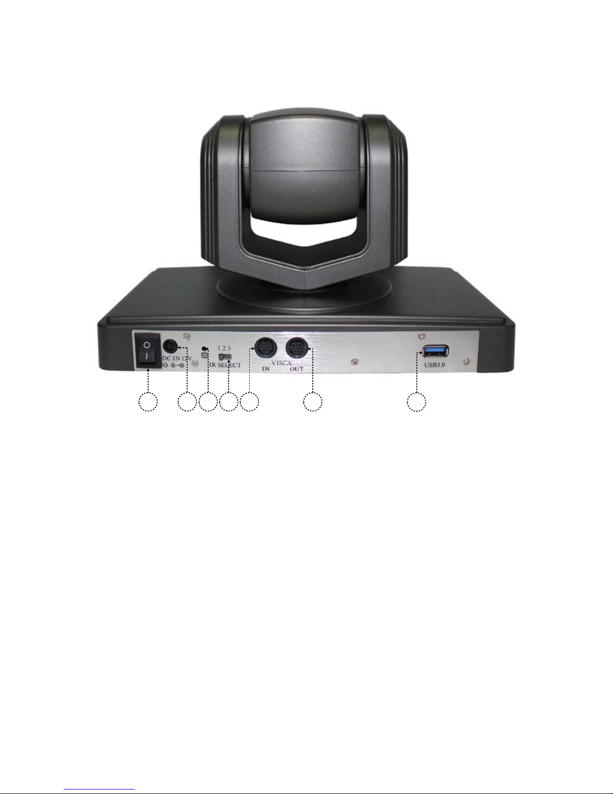
2Rear view of camera
76 8 9 11
12
10
Power switch
Power on/off button
DC IN 12V socket
Working with power adaptor along with Camera
IR Receiver
When use one remote control to operate three cameras, this switch will
decide which camera you’re operating.
VISCA IN port
When connect multi cameras to PC via RS-232C (VISCA IN), use serial cable
connect VISCA OUT of the first camera to VISCA IN of the second camera.
VISCA Out port/RS485
Used for connect multi camera, and RS-485 Control.
USB3.0
7 / 26
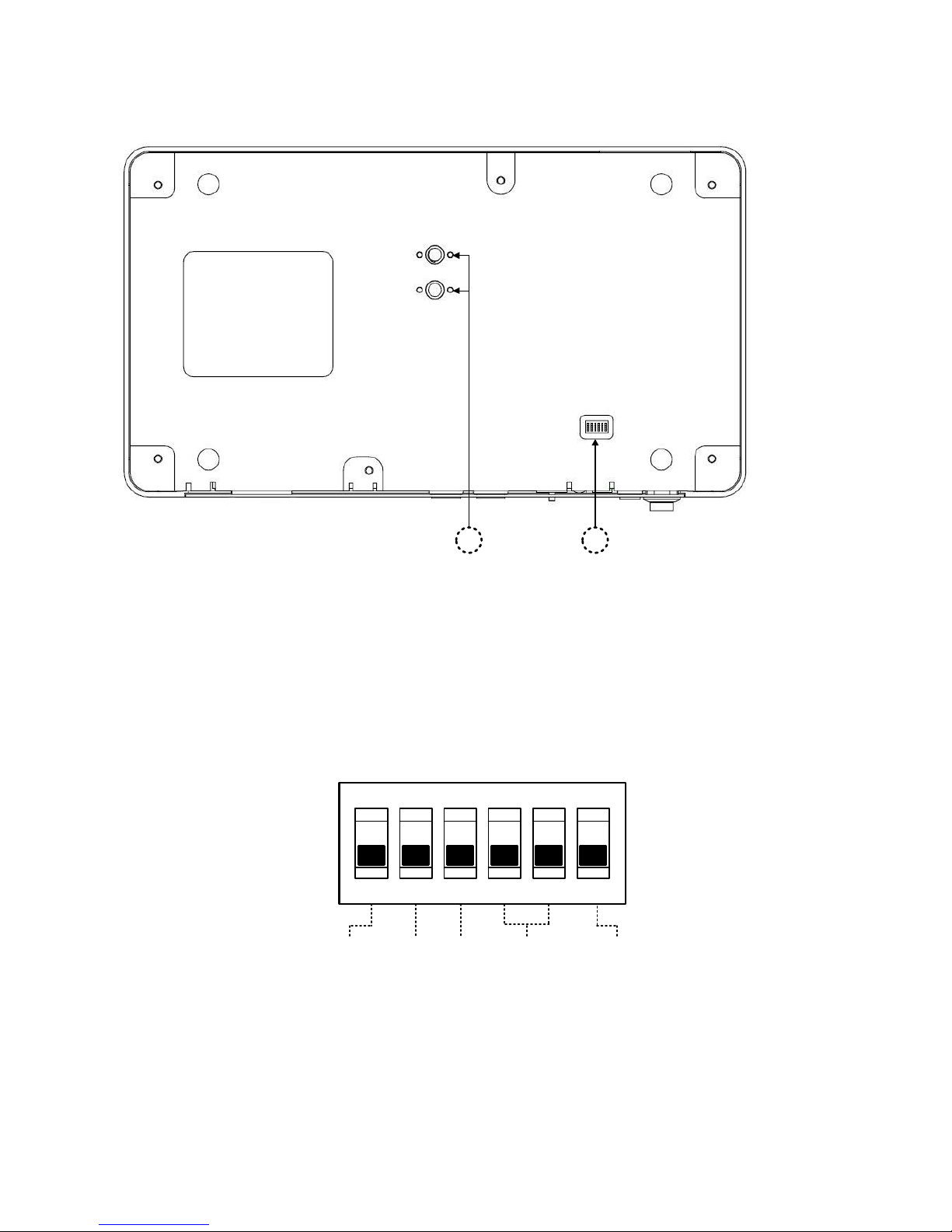
3Bottom of Camera
1
2
Tripod screw hole
When install the camera onto tripod, use these screw holes to fix on tripod.
Dip-switch
Used for select baud rate and remote signal output switch.
4Dip-switch Settings
ON KE
1 2 3 4 5 6
Dip-switch 1(Set Communication baud rate)
ON=>38400bps, OFF=>9600bps
(Please set the baud rate before turn on power. Baud rate setting
failed if turn off power.)

8 / 26
Dip-Switch 2(Set Control protocol)
ON: RS-485 &PELCO-D (ON=RS485&Pelco-D)
OFF: RS-232C&VISCA (OFF=RS232C &VISCA )
Dip-Switch 3 (Set as Upgrading)
Set dip switch 3 as ON, then you can do upgrading of the camera, Must
Set OFF as usual working.
Dip-Switch 4& 5 (Set address code)
When you used RS232C &VISCA to control multi-cameras, suggest to
set address code as OFF;
When you used RS-485 &PELCO-D to control multi-cameras, suggest to
refer to below Camera address code setting table;
Switch 6 (Set IR signal output switch)
When set as ON, it will receive the signal from remote control and
VISCA IN to control this device, if set it to OFF means close signal
output.
Camera address code setting
Dip-switch4 Dip-switch 5
1 OFF OFF
1 OFF ON
2 ON OFF
3 ON ON
Cable Connection info
VISCA RS-232C IN Reference
 Loading...