

HuddleCamHD 20X User Manual


Precautions………………………………………………………………………………………….
Safety Tips…………………………………………………………………………………………….
• Please read this manual carefully before using the camera.
• Avoid damage from stress, violent vibration or liquid intrusion during
transportation, storage or installation.
• Take care of the camera during installation to prevent damage to the
camera case, ports, lens or PTZ mechanism.
• Do not apply excessive voltage. (Use only the specified voltage.)
Otherwise, you may experience electrical shock.
• Keep the camera away from strong electromagnetic sources.
• Do not aim the camera at bright light sources (e.g. bright lights, the sun,
etc.) for extended periods of time.
• Do not clean the camera with any active chemicals or corrosive detergents.
• Do not disassemble the camera or any of the camera's components. If
problems arise, please contact your authorized dealer.
• After long term operation, moving components can wear down. Contact
your authorized dealer for repair.
Supplied Accessories…………………………………………………………………………….
• HD Color Video Camera (1)
• 12V/2.0A DC Power Adapter (1)
• Installation Bracket (1)
• Installation Screw (1)
• USB 3.0 Data Lines (3m), Serial Control Line, RS-232C to RS-485 Cable
Ver 1.1 6/26/14

• IR Remote Controller (1)
• User Manual (1)
Rear Board Connectors…………………………………………………………………………
High Definition Interface: USB 3.0
Control Signal Interface: Mini DIN-8 (VISCA IN, VISCA OUT/RS485)
Control Signal Configuration: Dip-Switch Pin 7/TTL Signal; Baud Rate: 9600bps
Power Supply Interface: DC 12V Socket
Electrical……….…………………………………………………………………………………….
Power Supply Adapter: 12V DC/2A
Input Voltage: 12V DC (10.5-14V DC)
Input Power: 24W (MAX)
Structure……………………………………………………………………………………………….
Material: Aluminum, Plastic
Dimensions (W x H x D): 9.84 in. (250mm) x 5.51 in. (140mm)
x 6.06 in. (154mm)
Mass: 2.84 lbs. (1.29 kg.)
Working Environment: Indoor
Operating Temperature: 32ºF to 113ºF
Storage Temperature: -14ºF to 140ºF
Color: Silver Gray
Ver 1.1 6/26/14
Rear Board & Function………………………………………………………………………..
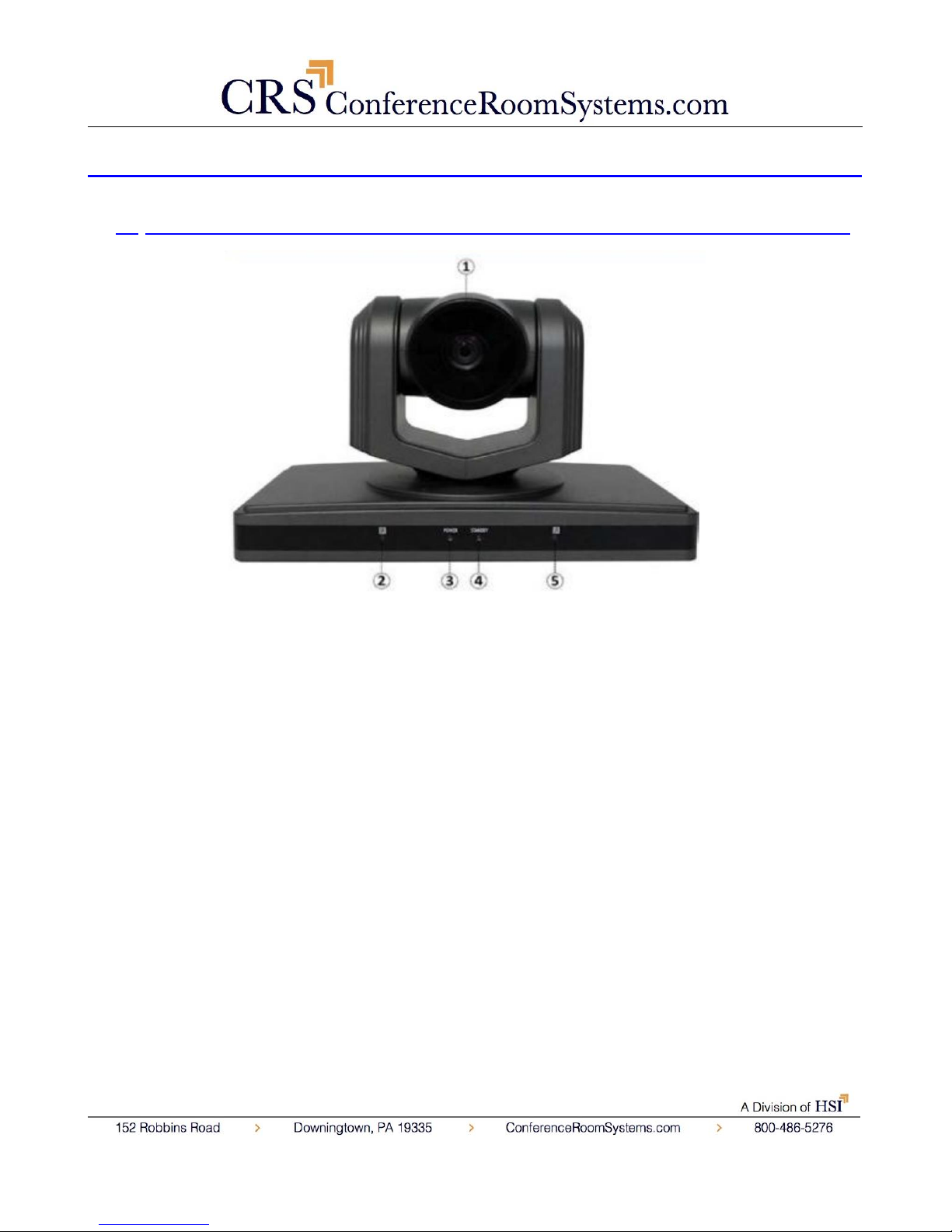
1. Front View…………………………………………………………………………………..
1. Lens
20x Optical Zoom.
2. IR Receiver
To receive IR remote controller signal.
3. Power LED
Blue LED blinks when unit is powered.
4. Stand by LED
Orange LED blinks for Stand-By status, Blue LED for Working Status.
5. IR Receiver
To receive IR remote controller signal.
Ver 1.1 6/26/14
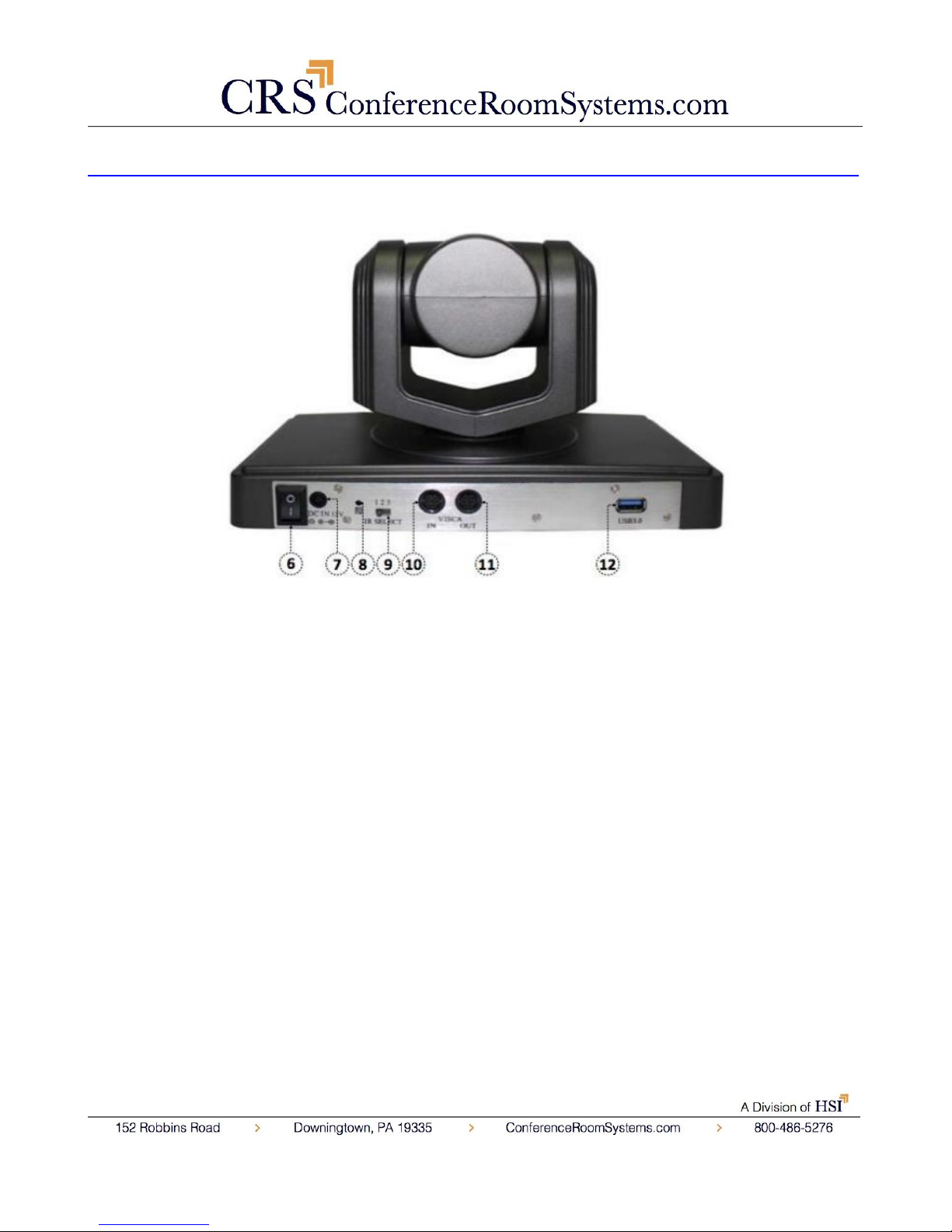
2. Rear View………………………………………………………………………………………….
6. Power Switch
Power On/Off button.
7. DC IN 12V Socket
Only use the Power Adapter supplied with this camera.
8. IR Receiver
To receive IR remote controller signals.
9. IR Selective Switch
When using only one remote to control more than one camera, this switch will
assign a unique ID to each camera.
10. VISCA IN Port
For hard wired remote control from a 3
rd
party PC, joystick, etc...
11. VISCA Out Port/RS485
Ver 1.1 6/26/14
Used for daisy chaining multiple cameras for RS-232 RS-485 control.
12. USB 3.0 Interface
For connection to PC.
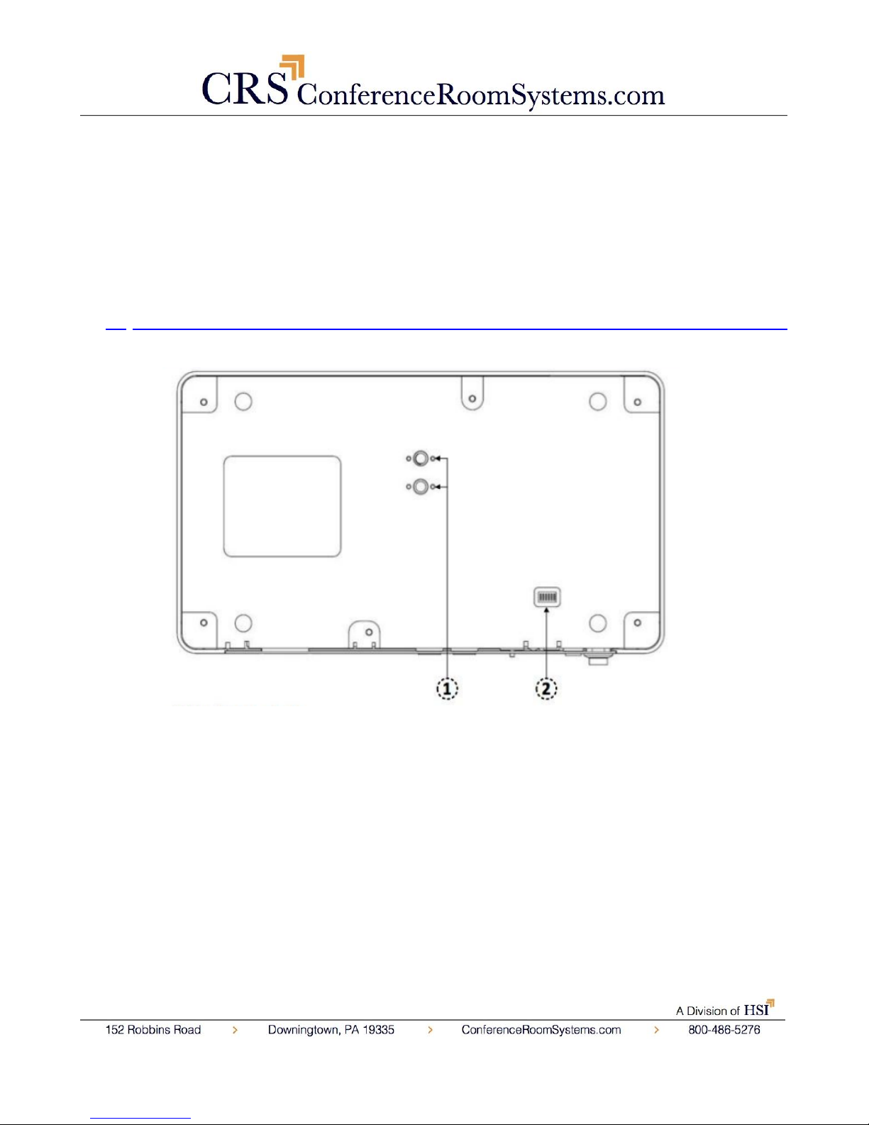
2. Bottom View………………………………………………………………………………….
1. Tripod
Will accept 1/4-20 bolt from 3rd party tripod, wall or ceiling mount.
2. Dip-Switch
Used for selecting baud rate and the remote signal output switch.
Ver 1.1 6/26/14
 Loading...