

Hubbell TX008‐2RS, TX011‐3R, TX011‐2S, TX011‐3T3, TX012‐2RS Installation, Operation And Maintenance Manual
...
INSTALLATION, OPERATION, AND
MAINTENANCE MANUAL FOR
THE HUBBELL MODEL TX/HX TANKLESS
WATER HEATER
ELECTRIC HEATER COMPANY
Edition 2011
2
Important Safety Information
1. You must read and follow all instructions. Serious bodily injury or death could occur
if you ignore this warning.
2. All circuit breakers and/or disconnect switches servicing the heater must be turned off
when installing, uninstalling, or repairing this water heater.
3. The Hubbell Tankless Water Heater must be grounded.
4. The unit must be installed by a licensed electrician and plumber.
5. The unit must be wired in accordance with the current version of the National
Electrical Code (US) or Canadian Electric Code (Canada).
6. This installation must comply with all national, state, and local plumbing and
electrical codes.
7. When the heater is not within sight of the electrical circuit breakers, an additional
local means of disconnection of all ungrounded conductors must be provided that is
within sight of the appliance or a circuit breaker lockout must be used. (Ref. NEC
422.31)
8. If the Hubbell Tankless Water Heater is installed in a location where water damage
could occur in the event of a leak, it is recommended that a drip pan be installed and
connected to a suitable drain. Alternatively, an active water leak detector and shut off
valve can be installed to turn off your water supply in the event a leak is detected.
9. If water supply has a high mineral content, a water softening system is recommended.
Damage to the water heater resulting from scale or hard minerals will not be covered
under warranty.
10. When the heater is installed in a well water system or if the plumbing system is prone
to introducing air into the heater, it is highly recommended that an air separator be
installed in the cold water feed to the heater to avoid possible failure of the heating
element and/or heating chamber.

3
TABLE OF CONTENTS
SECTION TITLE PAGE No.
I TANKLESS WATER HEATER OPERATING PRINCIPLE 4
II GENERAL DESCRIPTION AND CONSTRUCTION 5
III INSTALL ATION 9
IV OPERATION AND MAINTENANCE 21
V TROUBLESHOOTING 26
VI SERVICING & REPLACEMENT OF PARTS 32
VII PARTS LIST 36
VIII WARRANTY 37

4
SECTION I – TANKLESS WATER HEATER OPERATING PRINCIPLE
How the Hubbell Tankless Water Heater Works:
For the most part, operating the new tankless water heater is very similar to using any
traditional water heater system. However, it is very important that all of the set-up
procedures and operating instructions are carefully read to ensure maximum performance
and energy savings from the new water heater.
The Hubbell Tankless Water Heater does not store hot water like a conventional tank-type
water heater. It contains high powered heating elements that are capable of heating water
instantly on-demand as needed. As soon as there is a hot water demand, a sophisticated flow
sensor within the heater recognizes the demand and initiates the heating process. This
sensor measures the water flow rate while two other sensors measure the incoming and
outgoing water temperature. This information is transmitted continually to the
microprocessor controller which determines the precise amount of power to send to the
heating elements to heat the water to the desired temperature. The Hubbell tankless water
heater only uses as much power as is needed to meet the demand by fully modulating the
heating elements from 0 to 100%.
It is important to keep in mind that all tankless water heaters are subject to a maximum flow
rate. If this flow rate is exceeded, the heater will not be capable of fully heating water. The
amount of water that can be heated by the tankless water heater at any given time will
depend on the model selected and the incoming water temperature. See the charts in Section
II to determine the maximum flow rates.
Moreover, since a tankless water heater eliminates the ongoing thermal losses caused by
storing hot water in a tank, there will be a significant energy savings compared to a
conventional tank type water heater.
5
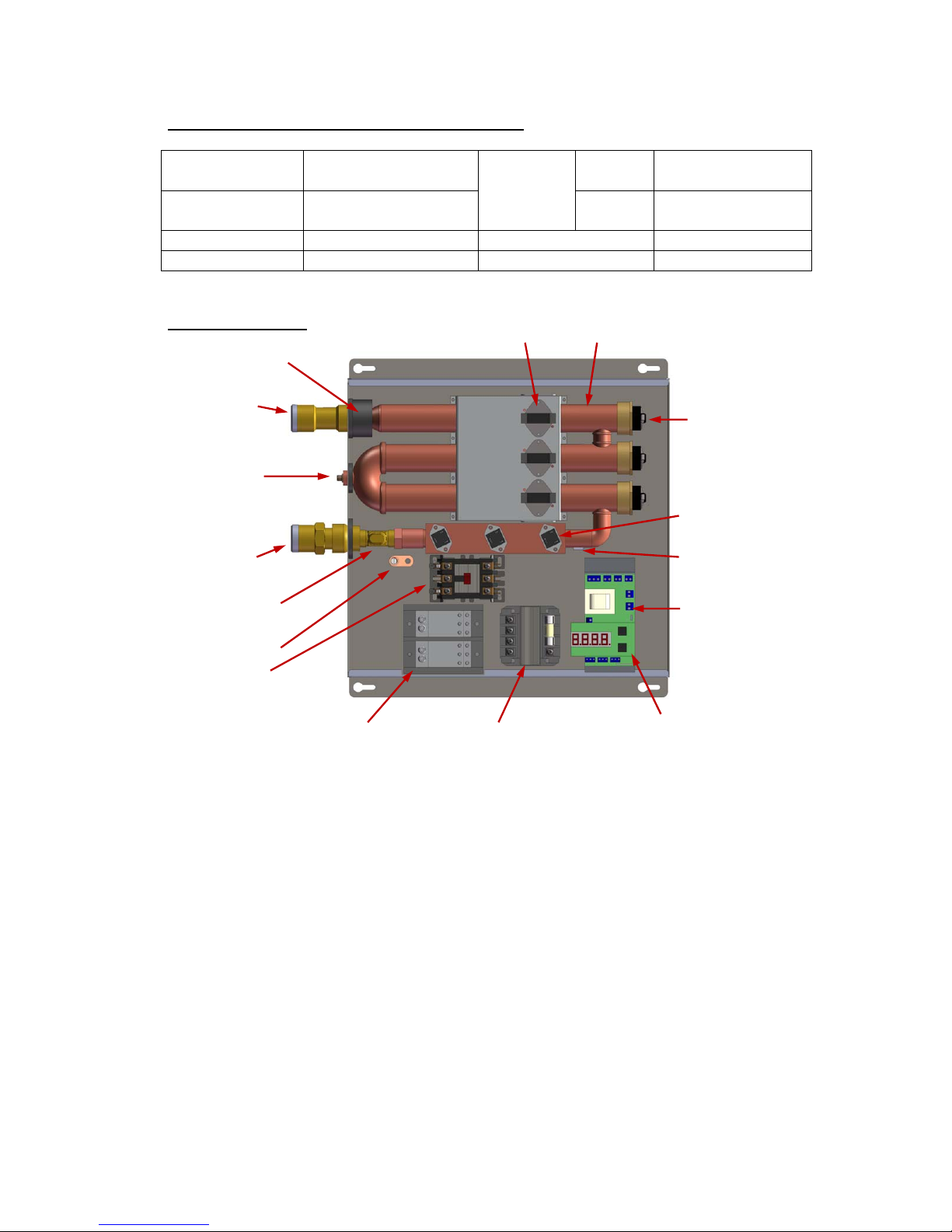
Heating Elements
Heating Chamber Hi-Limit Switches
Inlet Thermistor
Outlet Thermistor
Element Switching
Devices (Triacs)
Temperature
Controller
LED Digital Display
(with buttons)
Power Distribution Block
Ground Lug
Hot Water
Outlet
Cold Water
Inlet
Drain
Flow Meter
Magnetic
Contactor
Transformer
SECTION II – GENERAL DESCRIPTION AND CONSTRUCTION
Technical Specifications Common to All Models:
Materials: Copper Exchanger /
Stainless Steel Casing
Plumbing
Connection:
Low
Flow
¾” Copper, CPVC,
or PEX Tube
Energy
Efficiency:
98%
High
Flow
1” MNPT
Voltage: 208-600 Volts Operating Range: 5 – 150 psi
Frequency: 50 / 60 Hz Protection: Thermal Auto Reset
Product Overview:
Notes:
1. Power distribution blocks are only installed on single phase models.
2. Magnetic contactors are only installed on 3-phase models.
3. Transformers are only installed on 3-phase models over 240 volts.
4. 2-Element models will have a plug in the lowest element chamber and have only two hi-
limit switches and triacs installed.
Typical 2/3-Element Model
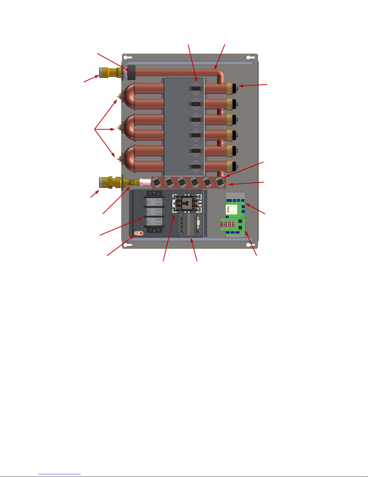
6
Heating Elements
Inlet Thermistor
(beneath triac
plate)
Outlet Thermistor
Element Switching
Devices (Triacs)
Temperature
Controller
LED Digital Display
(with buttons)
Magnetic Contactor
Ground Lug
Hot Water
Outlet
Cold Water
Inlet
Drains
Flow Meter
Hi-Limit Switches
Heating Chamber
Transformer
Power
Distribution
Bl
ock
Notes:
1. Power distribution blocks are only installed on single phase models and 3-phase models
that require two magnetic contactors. Single phase models use a 2-pole power
distribution block.
2. Magnetic contactors are only installed on 3-phase models. One or two magnetic
contactors may be installed as required.
3. Transformers are only installed on 3-phase models over 240 volts.
Typical 6-Element Model
7
Tankless Water Heater Maximum Flow Rates:
5°F 10°F 20°F 30°F 40°F 50°F 60°F 70°F 80°F 100°F 120°F 140°F
8
10.9 5.5 2.7 1.8 1.4 1.1 0.9 0.8 0.7 0.5 0.5 0.4
11
15.0 7.5 3.8 2.5 1.9 1.5 1.3 1.1 0.9 0.8 0.6 0.5
12
16.4 8.2 4.1 2.7 2.1 1.6 1.4 1.2 1.0 0.8 0.7 0.6
13
17.8 8.9 4.4 3.0 2.2 1.8 1.5 1.3 1.1 0.9 0.7 0.6
14
19.1 9.6 4.8 3.2 2.4 1.9 1.6 1.4 1.2 1.0 0.8 0.7
15
20.5 10.3 5.1 3.4 2.6 2.1 1.7 1.5 1.3 1.0 0.9 0.7
16
21.9 10.9 5.5 3.6 2.7 2.2 1.8 1.6 1.4 1.1 0.9 0.8
18
24.6 12.3 6.2 4.1 3.1 2.5 2.1 1.8 1.5 1.2 1.0 0.9
20
27.3 13.7 6.8 4.6 3.4 2.7 2.3 2.0 1.7 1.4 1.1 1.0
21
28.7 14.4 7.2 4.8 3.6 2.9 2.4 2.1 1.8 1.4 1.2 1.0
24
32.8 16.4 8.2 5.5 4.1 3.3 2.7 2.3 2.1 1.6 1.4 1.2
25
34.2 17.1 8.5 5.7 4.3 3.4 2.8 2.4 2.1 1.7 1.4 1.2
27
36.9 18.5 9.2 6.2 4.6 3.7 3.1 2.6 2.3 1.8 1.5 1.3
30
20.5 10.3 6.8 5.1 4.1 3.4 2.9 2.6 2.1 1.7 1.5
31
21.2 10.6 7.1 5.3 4.2 3.5 3.0 2.6 2.1 1.8 1.5
33
22.6 11.3 7.5 5.6 4.5 3.8 3.2 2.8 2.3 1.9 1.6
36
24.6 12.3 8.2 6.2 4.9 4.1 3.5 3.1 2.5 2.1 1.8
40
27.3 13.7 9.1 6.8 5.5 4.6 3.9 3.4 2.7 2.3 2.0
42
28.7 14.4 9.6 7.2 5.7 4.8 4.1 3.6 2.9 2.4 2.1
48
32.8 16.4 10.9 8.2 6.6 5.5 4.7 4.1 3.3 2.7 2.3
50
34.2 17.1 11.4 8.5 6.8 5.7 4.9 4.3 3.4 2.8 2.4
54
36.9 18.5 12.3 9.2 7.4 6.2 5.3 4.6 3.7 3.1 2.6
Maximum Flow Rate (GPM) at Temperature Rise (°FΔT)
Power (kW)
1. Shaded values indicate that a High Flow (HX) unit is required.
2. Blank values indicate that the flow rate will exceed the flow capability of the flow meter.
3. For alternate power (kW) values, the maximum flow rate can be calculated using the
formulas on the following page.
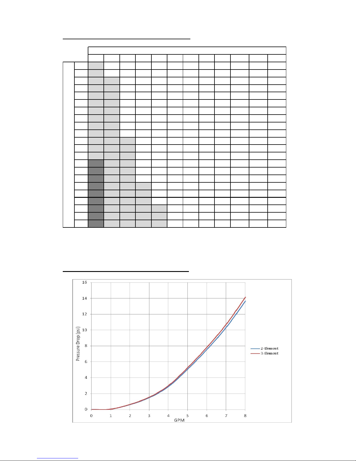
Tankless Low Flow Pressure Drop Chart (TX):
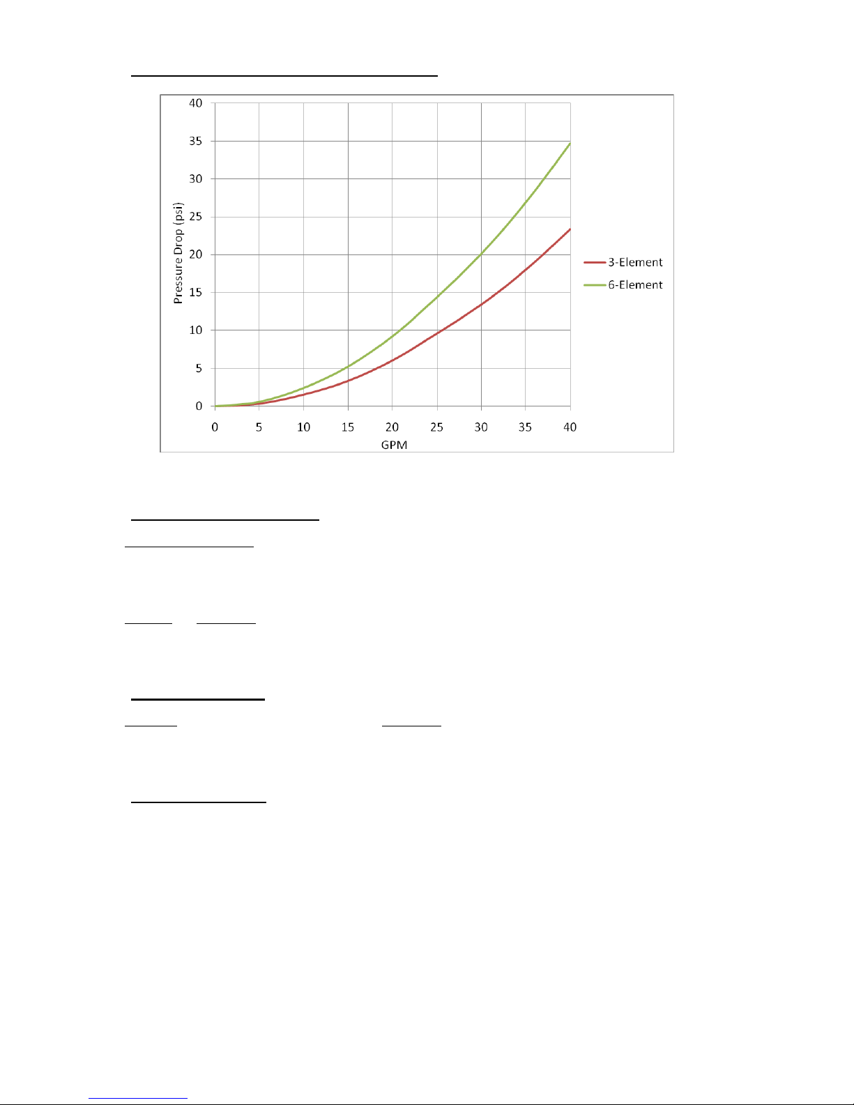
8
Tankless High Flow Pressure Drop Chart (HX):
Wattage De-rating Formula:
Applied Voltage
2
× Rated Wattage = Actual Wattage
Rated Voltage
2
For example: If installing a 27 kW unit when actual voltage is 212 V,
212
2
=
44,944
= 0.78 × 27,000 W = 21,060 W @ 212 V
240
2
57,600
Amperage Formula:
Watts
= Amps (Single Phase)
Watts
÷1.73 = Amps (3-Phase)
Volts Volts
Flow Rate Formulas:
To determine power (kW) requirement
____GPM × ____ °F ΔT × 0.1465 = ____ kW
To determine temperature rise
____ kW × 6.824 ÷ ____ GPM = ____°F ΔT
To determine flow rate
____ kW × 6.824 ÷ ____ °FΔT = ____ GPM

9
SECTION III – INSTALLATION
WARNING: Serious bodily injury or death may occur if the following warnings are
ignored.
• All circuit breakers and/or disconnect switches servicing this heater must be turned
off before installing, repairing or uninstalling this water heater.
• Installation of this product is restricted to indoor locations.
• Installation
MUST
be done by a licensed electrician and licensed plumber.
Locating and Mounting Instructions:
The Hubbell tankless water heater can be installed just about anywhere. Due to the small
size of the water heater, it can be mounted in many small spaces. However, there are some
important guidelines to follow that will ensure that the installation is both safe and
convenient in the event that future servicing is required.
This product is designed to be installed indoors only. The unit may be installed in an
outdoor location as long as it is mounted in a suitable enclosure that protects it from rain,
splashed water, direct sunlight, debris, and insects. This product should NOT be installed in
a location where it may be subjected to freezing temperatures. If the water inside the tankless
water heater freezes, it can cause severe and permanent damage that is not covered under the
warranty. If you suspect that the tankless water heater may have frozen, do not turn on the
heater until it has thawed and it has been inspected for leaks.
When selecting an installation location, give consideration to the existing plumbing
configuration, location of your main electrical panel, and location of the point of use. Try to
choose a location that does not require major plumbing alterations, that is close to the main
electrical panel (this will reduce the amount of wire needed to install), and that is physically
close to the hot water fixtures. By locating the heater close to the points of use, this will
reduce the amount of time it takes for the hot water to travel from the water heater to the
point of use. Consideration should also be given to future servicing. Do NOT locate the
water heater in a location that is difficult to access. In most cases, installing the tankless
water heater in the same location as the old conventional tank-type water heater will make
the most sense.
Avoid installing the tankless water heater in a location prone to excessive humidity,
moisture, or dust, or in an area where it may be splashed with water or other liquids. Do
NOT install under water pipes or air conditioning lines that might leak or condense moisture
that could then drip onto the heater. Do NOT install above electrical boxes or junctions.
If installation of the water heater will be on a second floor, make sure that all code
requirements for such installations as required for your area are followed. Hubbell
recommends that a drip pan (connected to a drain) is installed below the water heater to
avoid property damage in the unlikely event of a leak. Alternatively, an active water leak
detector and shut-off valve designed to turn off the water supply in the event that a leak is
ever detected may be installed.
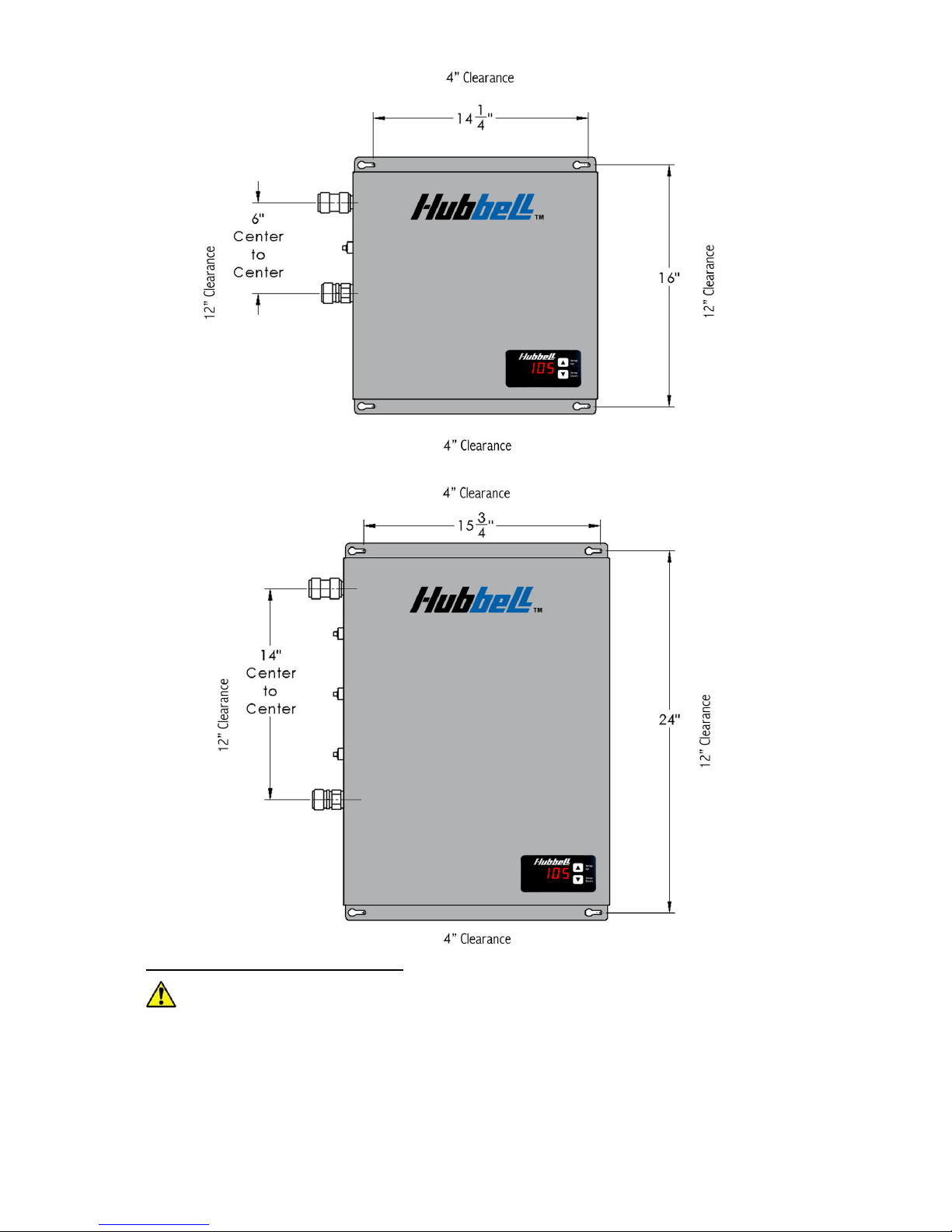
Mounting the unit:
• Leave a minimum of 12” to both sides and 4” on the top and bottom of the unit.
• Mount the water heater securely to the wall by putting four (4) screws through the
mounting holes.
• Install a ¼” diameter bead of sealing caulk around the entire perimeter of the heater
between the heater back panel and the wall. This prevents any moisture or debris
from accumulating.
10
Plumbing Installation Instructions:
IMPORTANT INFORMATION:
• Ensure all fitting installations comply with local plumbing and building codes.
•
This water heater does not require a temperature and pressure (T&P) relief valve.
You may install a T&P relief valve if the county, city or state plumbing code requires
it.
• Installations in the Commonwealth of MASSACHUSETTS and KENTUCKY require
a
T&P
relief valve.
11
• When connecting to a plumbing system that utilizes Flex or PVC, a
T&P
relief valve
should be used as added safety.
•
Do not connect the unit directly to CPVC pipe. You must use at least three feet of
copper pipe prior to connecting to any CPVC connection.
• WARNING:
Do not solder any pipes with the unit connected to the pipes. Doing so
will damage the flow meter and void your warranty.
•
Before energizing the heater, run water for a minimum of three (3) minutes and
verify that all air has been removed.
•
Installation of an air separator device is recommended for installations where air can
be easily introduced into the water system (i.e. Well water systems, lake pumps, and
other municipal systems).
• A shut off valve MUST be installed on inlet side of unit. A shut off valve on the
outlet is recommended.
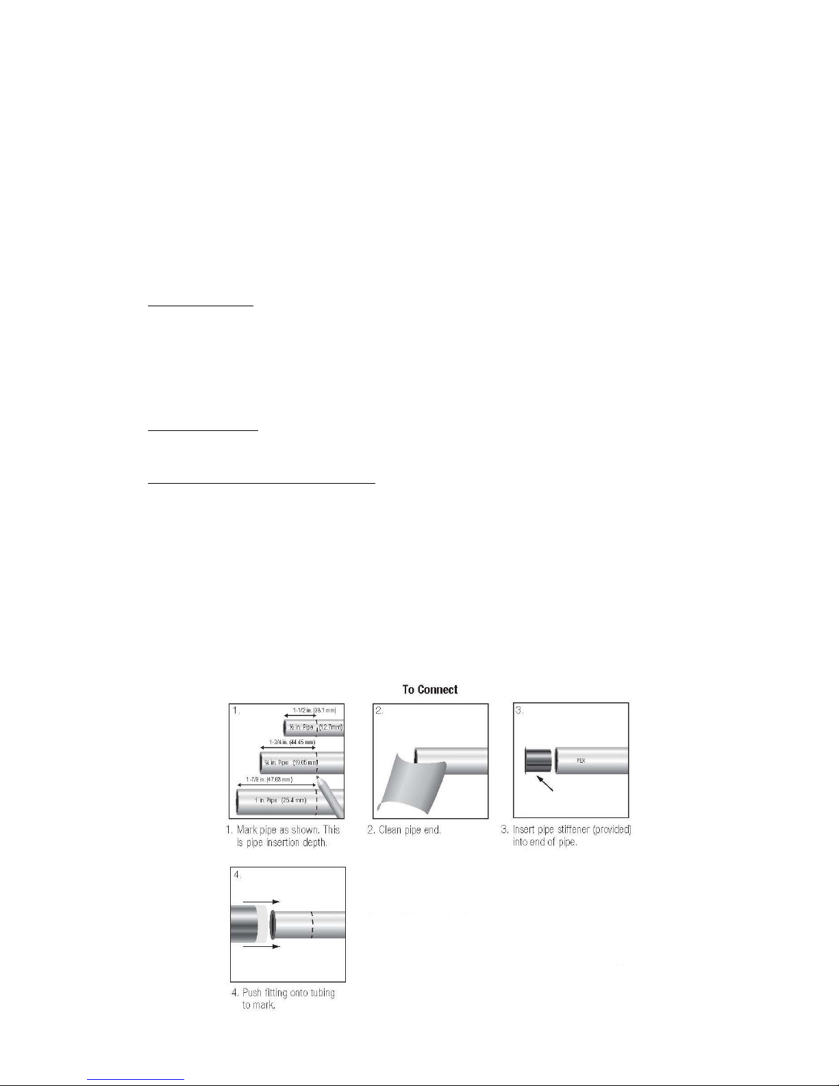
Pipe Preparation:
• Cut the tube so that the ends are square. WARNING: Ensure that there are no burrs or
damage to the
cut end. This will prevent any damage to the internal o-ring.
• Once the tubing end is cut square and clean, mark the pipe to be installed at a distance
of 1 ¾” from the end of the pipe. This is the insertion depth.
• Check that fittings and tubing are
clean, in good condition and are free from damage
and foreign objects.
Flushing the Line:
•
Before connecting the copper pipe to the water heater, it is extremely important to
flush the lines to eliminate all plumbing paste, residue, or debris in the lines.
Installation to Quick-Connect Fitting:
• If using PEX tubing, insert the supplied stiffener into the end of the pipe.
•
To assemble correctly, the tubing needs to be pushed into the fitting until it reaches
the mark previously scribed. Push the tube firmly with a slight twisting action until it
reaches the tube stop.
• Connect the cold water line to the water heater inlet marked cold water. Connect the
hot water line to the water heater outlet marked hot water.
•
After inserting both fittings, open the hot water faucet and allow water to run
through the water heater for at least three (3) minutes, cycling the flow on and off
every minute. This process clears all the air from the lines and must be performed
prior to turning on the power at the unit.
WARNING:
Failure to do this may
damage the flow meter or heating elements and will void your warranty.
12
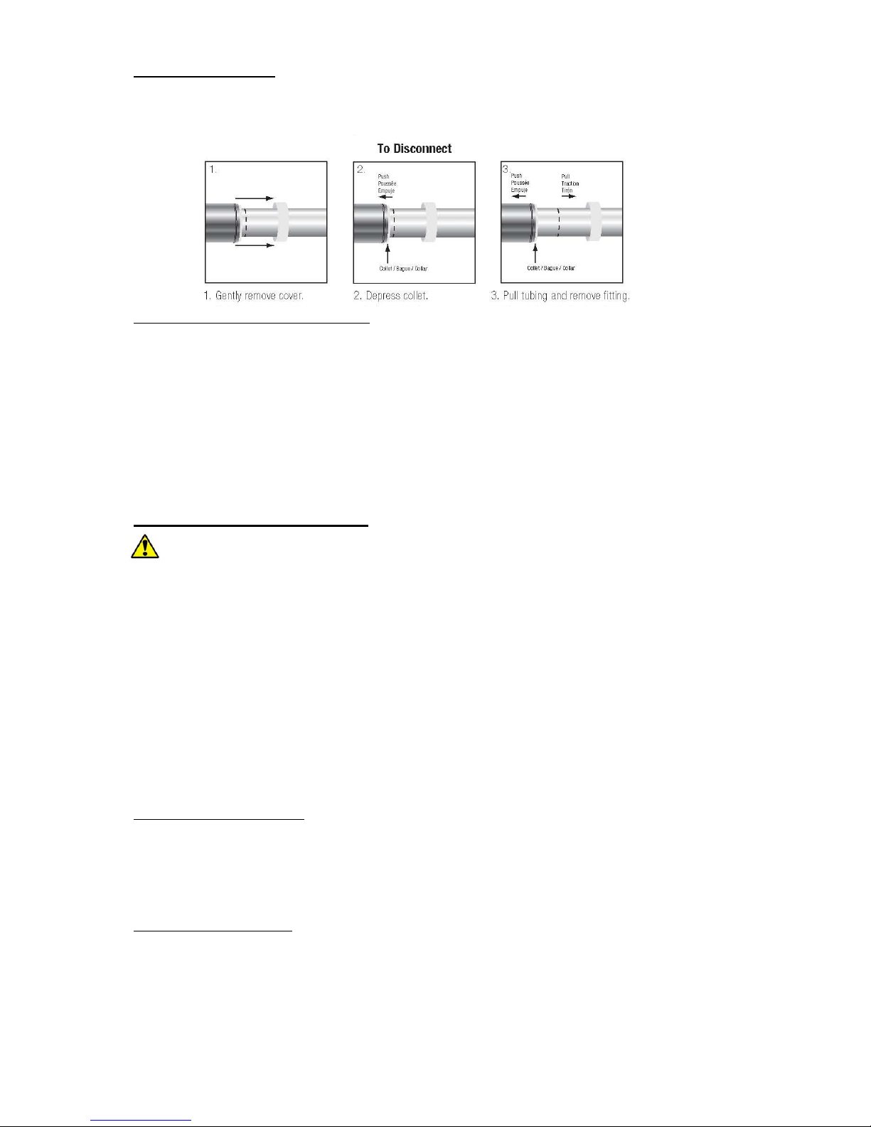
Disconnecting a Joint:
• Gently remove the cover to the quick-connect fitting.
• Depress the collet of the quick-connect fitting and pull the tubing to remove the quick-
connect fitting.
Checking for Leaks and Purging Air:
• If unit has been wired, verify all circuit breakers supplying power to the unit are
turned off.
• Open all hot water taps supplied by the unit and inspect water connections for leaks.
• With all hot water taps still open, allow the water to run for a minimum of 3
minutes. Inspect each tap to ensure all air in the lines has been purged. This process
purges all the air from the water lines and MUST be performed prior to turning on the
power at the unit.
WARNING:
FAILURE TO FOLLOW THIS STEP CAN CAUSE
PERMANENT DAMAGE TO THE HEATING ELEMENTS.
• Close all hot water taps.
Electrical Installation Instructions:
IMPORTANT INFORMATION:
• The unit must be wired in accordance with the current version of the National
Electrical Code (US) or Canadian Electric Code (Canada).
• The unit must have its own independent circuits.
• When the heater is not within sight of the electrical circuit breakers, an additional
local means of disconnection of all ungrounded conductors must be provided that is
within sight of the appliance or a circuit breaker lockout must be used. (Ref. NEC
422.31)
• Wire entry must be through the electrical KO provided in the bottom of the unit.
• For Canada, per Canadian Electric Code, C22.1-02, the unit must be wired by a single
feed installation with one (1) double-pole circuit breaker.
• For US, the unit may be wired by a single feed installation with one (1) double-pole
circuit breaker or by a multiple feed installation with multiple double-pole circuit
breakers.
Wiring to the water heater:
• Connect the pow er wi re from the main pa nel to the power dist ribution block or
magnetic contactor as applicable.
•
Connect the main ground wire to the ground lug in the heater.
•
Make sure the connections are securely tightened.
Electrical Specifications:
Listed in the following tables are the electrical specifications for each tankless water heater
model.
 Loading...