

Page 1

Pub.: 42004-071F
GAI-TRONICS® CORPORATION
A HUBBELL COMPANY
Model TI984 Telephone Interface
TABLE OF CONTENTS
General Information ..................................................................................................................1
Installation.................................................................................................................................2
Site Requirements .............................................................................................................................. 2
Wiring Instructions ...........................................................................................................................2
Telephone Line Connections .............................................................................................................4
Power .................................................................................................................................................4
Page/Party® Connections...................................................................................................................5
Remote Connections..........................................................................................................................5
Programming: General Instructions.........................................................................................6
Programming Procedure ...........................................................................................................7
Entering and Exiting the Programming Mode.................................................................................7
Selecting an Incoming Access Method .............................................................................................. 8
Voice Access Method.....................................................................................................................................8
Ring Access Method....................................................................................................................................... 8
Selective Access Method................................................................................................................................8
Manual Access Method ..................................................................................................................................9
Operating Instructions...............................................................................................................9
Answering Incoming Calls ................................................................................................................9
Terminating Calls............................................................................................................................10
Number of Incoming Rings ............................................................................................................. 10
Hang-up Delay.................................................................................................................................10
Universal Parameters ...................................................................................................................... 10
Internal/External Day/Night Switch..............................................................................................................10
Programming Table.................................................................................................................11
Adjustments .............................................................................................................................13
Programming Summary Chart.......................................................................................................13
Specifications...........................................................................................................................14
Replacement Parts........................................................................................................................... 14
GAI-Tronics Corporation P.O. Box 1060, Reading, PA 19607-1060 USA
610-777-1374 n 800-492-1212 n Fax: 610-775-6540
VISIT WWW.GAI-TRONICS.COM FOR PRODUCT LITERATURE AND MANUALS
Page 2

42004-071F
Model TI984 Telephone Interface
Confidentiality Notice
This manual is provided solely as an operation, installation, and maintenance guide and contains sensitive
business and technical information that is confidential and proprietary to GAI-Tronics. GAI-Tronics
retains all intellectual property and other rights in or to the information contained herein, and such
information may only be used in connection with the operation of your GAI-Tronics product or system.
This manual may not be disclosed in any form, in whole or in part, directly or indirectly, to any third party.
General Information
The Model TI984 is a telephone interface designed to
provide a communication path between the GAI-Tronics
Page/Party® industrial communication system and a public
or private telephone system.
The telephone interface allows individuals to access the
page line and the party line of the Page/Party® system
while using a standard telephone. The programming
options of this interface make the unit extremely versatile.
Because the demands on your communication system may
vary from the day shift to the night shift, this interface can
be configured for two independent sets of operating
parameters -- day mode and night mode. For example, the
method used to receive incoming telephone calls can be
configured differently for each mode.
Incoming telephone calls can access the Page/Party
system using one of four incoming access methods: voice
access, ring access, selective access, or manual access. The incoming access method that is selected
determines the way the incoming call gains access to the Page/Party® system. The telephone interface
can be configured to transfer the call directly to the designated page line or require the intervention of a
switchboard operator.
The day mode can be configured for manual access, while the night mode is configured for ring access.
Review the programming options listed in this manual to identify the optimal configuration for your
facility.
Note: The TI984 is registered with the Federal Communications Commission (FCC). As the owner of
this device, you must give the following information to the operating telephone company before
connecting or disconnecting the device:
1. Notice of your intent to use privately-owned telephone equipment.
2. The particular telephone numbers to be used.
®
Model TI984 Telephone Interface
3. Model: GAI-Tronics’ TI984 Programmable Telephone Interface
4. FCC Registration Number: ADG9ZP-16816-VH-E
5. Ringer Equivalence Number (REN): 0.4B
GAI-Tronics Corporation P.O. Box 1060, Reading, PA 19607-1060 USA
610-777-1374 n 800-492-1212 n Fax: 610-775-6540
VISIT WWW.GAI-TRONICS.COM FOR PRODUCT LITERATURE AND MANUALS
Page 3
PAGE 2 of 14
MODEL TI984 TELEPHONE INTERFACE 42004-071F
WARNING
This equipment generates, uses, and can radiate radio frequency energy and if not installed and
used in accordance with the instruction manual, may cause interference to radio communications.
It has been tested and found to comply with the limits for a Class “A” computing device pursuant
to Subpart J or Part 15 of the FCC Rules, which are designed to provide reasonable protection
against such interference when operated in a commercial environment. Operation of the
equipment in a residential area is likely to cause interference. If interference occurs, the user, at
their own expense, will be required to take whatever measures are necessary to correct this
interference.
Installation
WARNING
This device can present a 115/230 V ac shock hazard. Please use care when handling this device.
Be sure that the ac power is not connected during wiring.
Site Requirements
The Model TI984 should be mounted near both the GAI-Tronics Page/Party® system and the RJ11C
receptacle from the telephone company or Private Branch Exchange (PBX). The distance from the TI984
to one Page/Party® station should be such that someone can adjust the controls on the TI984 while
listening to the handset of the station. The distance from the RJ11C receptacle should be less than 14
feet, to allow the use of the supplied plug-in cable.
Note: If there are no handset stations, contact the GAI-Tronics Field Service Department for instructions
at 800-492-1212, 8 a.m. to 4:30 p.m., Monday through Friday, Eastern Standard Time (EST).
The TI984 should be installed in an environment within the temperature range of 0º C to +70º C
(+32º F to +158º F).
Install the TI984 away from equipment that could cause excessive electrostatic, or electromagnetic
interference, or equipment that produces high voltage.
Wiring Instructions
1. Remove the front cover by loosening the 4 captive screws and swinging the cover open to the left.
Disconnect the ribbon cable and the telephone cable, and pull the hinges out of the holes in the rear
enclosure.
2. Determine which of the 4 available conduit locations is to be used. Drill spots have been provided for
use with either a chassis punch or hole saw.
f:\standard ioms - current release\42004 instr. manuals\42004-071f.doc
05/03
Page 4
PAGE 3 of 14
MODEL TI984 TELEPHONE INTERFACE 42004-071F
Recommendations:
• Remove the Printed Circuit Board Assemblies (PCBAs) until installation of the conduit is
complete.
• Use 1.25-inch conduit hub assemblies because this size makes the proper contact with the supplied
grounding plate. In using a conduit hub assembly other than the recommended size, it is the
installer’s responsibility to provide the proper earth ground bonding. Hub(s) must be connected to
the conduit before being connected to the enclosure.
• The recommended hubs are: GAI-Tronics 14611-004 (1.25 inch) and Myers ST-4 (1.25 inch).
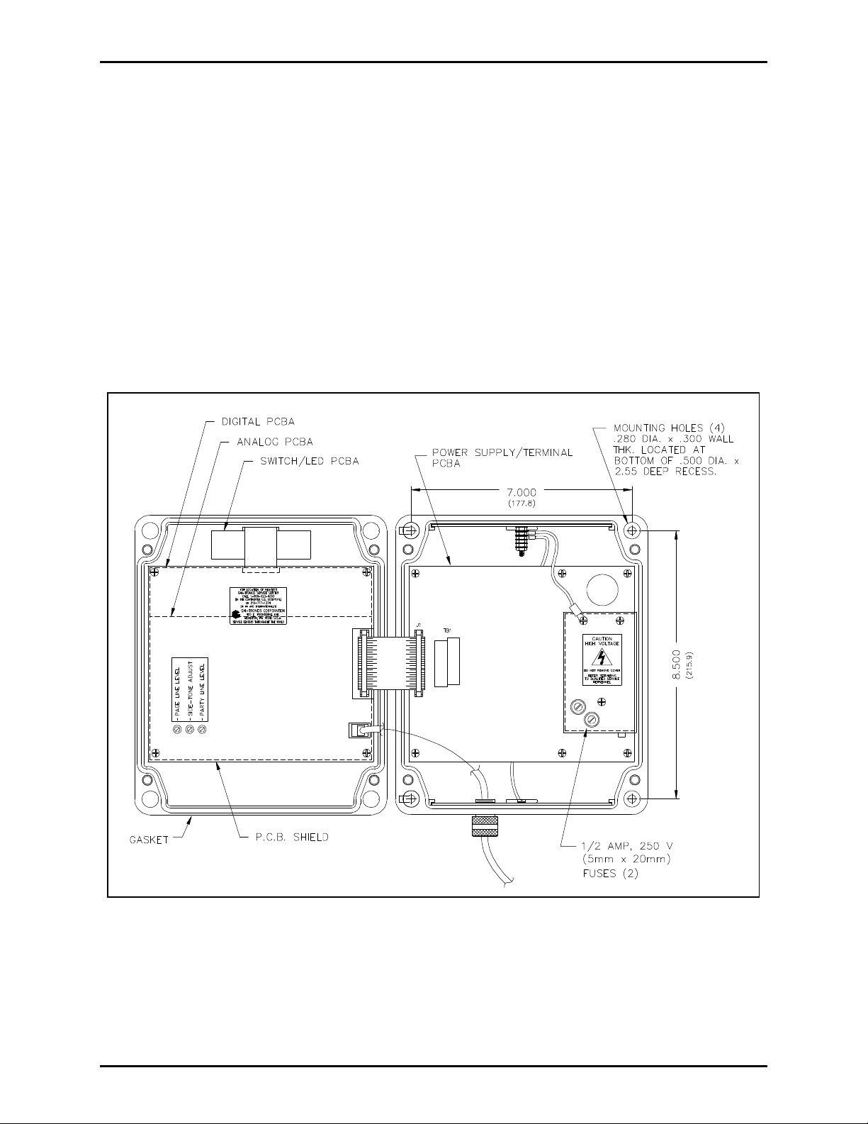
3. Install the rear enclosure on the wall using screws in the 4 corner holes. See Figure 1 for the location
of these holes.
4. Connect the conduit to the TI984, and run the wires through the conduit to connect power and signal
lines to the proper terminals as shown in Figure 2.
Figure 1. Mounting Details
f:\standard ioms - current release\42004 instr. manuals\42004-071f.doc
05/03
Page 5
PAGE 4 of 14
MODEL TI984 TELEPHONE INTERFACE 42004-071F
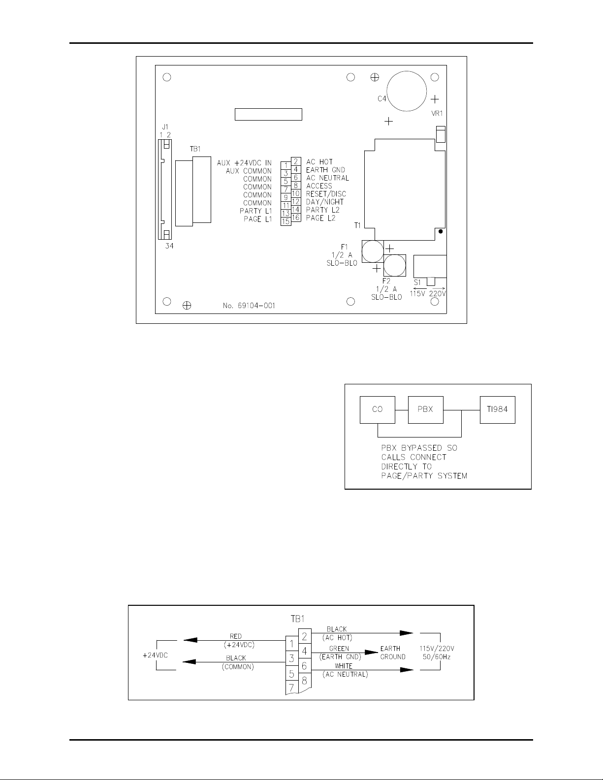
Figure 2. Termination Area
Telephone Line Connections
The TI984 should be connected to the Central Office (CO)
RJ11C jack from the telephone company or to a PBX with
the 14-foot RJ11 interconnect cable. See your telephone
company if a CO jack needs to be installed or extended.
The connection outlined in Figure 3 is recommended
because it allows the use of all the available types of
incoming modes. If the call from the CO is to be directly
connected to the Page/Party® system, use the bypass feature
available on the PBX.
Figure 3. Telephone Connections
Power
The unit can be powered by 115 or 230 V ac (50 to 60 Hz), or 24 V dc. If using ac power, connect the ac
neutral wire (white) to terminal 6 and the ac hot wire (black) to terminal 2. See Figure 4. The earth
ground wire (green or green/yellow stripe) should be connected to terminal 4. Set the Power Selector
switch at the lower right of the power supply to the proper voltage setting (115 or 230 V).
Figure 4. Power Connections
f:\standard ioms - current release\42004 instr. manuals\42004-071f.doc
05/03
Page 6

PAGE 5 of 14
MODEL TI984 TELEPHONE INTERFACE 42004-071F
If using a dc source, either a battery and/or a UL-approved power supply/battery charger should be used.
The power supply must be capable of providing at least 1.4 amperes dc @ 23-28 V. Connect the positive
wire to terminal 1 and the negative wire to terminal 3 (the Power Selector switch may be in either
position). See Figure 4 for wiring details. Terminal 4 should be connected to the earth ground for
maximum safety.
For convenient wiring, GAI-Tronics offers an 8-conductor cable, Model 60038-101. This cable has three
14 AWG conductors for power and ground and five 18 AWG conductors for page and party line audio
connections and a spare. If another cable is used, note that the audio wires must be twisted pairs but need
not be shielded.
Note: Each power input is fuse protected. The 2 fuses are located on top of the power supply shield.
Both fuses are rated ½ amp. See Figure 1 for the location of these fuses.
Page/Party® Connections
The TI984 needs to be connected to both the
page line and the party line of the
Page/Party® system. See Figure 5.
Party line connections should be made to
terminals 13 and 14 as shown in Figure 5,
and on the connection diagram printed on the
power supply circuit board (rear enclosure).
Figure 5. Page/Party® Connections
In a multi-party system, one of the party
lines must be selected as the designated party line. The TI984 only connects to the designated party line.
Note: The 33-ohm line balance resistor must be removed from the designated party line of the
Page/Party® system. This resistor is generally located in a separate assembly called a line balance
network. Only the line balance resistor for the party line should be disconnected. Page line connections
should be made to terminals 15 and 16.
Remote Connections
The ACCESS, RESET, and DAY/NIGHT switches on the TI984’s front cover can be connected at remote
locations if the unit is located away from the switchboard or primary user. See Figure 6.
The ACCESS switch manually connects between the Page/Party® system and the outside telephone line.
The RESET switch can be used to disconnect calls. The DAY/NIGHT switch is used to switch the unit
between the two modes of operation.
Note: A programming change is required to use the remote DAY/NIGHT switch.
Day Mode Night Mode
In Use
Not in Use
Constant On Flashing, mostly on
Constant Off Flashing, mostly off
f:\standard ioms - current release\42004 instr. manuals\42004-071f.doc
05/03
Page 7

PAGE 6 of 14
MODEL TI984 TELEPHONE INTERFACE 42004-071F
Figure 6. Remote Connections
Terminals 7 and 8 are used for the remote ACCESS switch; terminals 9 and 10 are used for the remote
RESET switch; terminals 11 and 12 are used for the remote DAY/NIGHT switch. The ACCESS and RESET
switches should be normally open (N.O.) momentary switches. The DAY/NIGHT switch must be a
two-position single pole switch and can be marked to show the operator which mode has been selected. If
using an automatic timing system, the relay contact should be closed during day mode and open during
night mode.
Note: Terminals 7, 9, and 11 are common to all switches; therefore, a 4-wire cable may be used to
connect all 3 remote switches.
When wiring is complete, replace the front cover, and connect the ribbon cable and the telephone cable.
Programming: General Instructions
The Model TI984 Telephone Interface’s programmable features allow it to be tailored to different needs.
The unit is shipped from the factory programmed with a set of default parameters listed in the
Programming Summary Chart on page 13. Read the entire Programming section, record the desired
selections in the column titled User Programming, and then proceed to program the unit. We recommend
that you record your programming choices for future reference.
The TI984 is programmed from a touch-tone (DTMF) telephone. If the programmer is working from an
outside line, the Page/Party® system must first be accessed by calling the number to which the interface is
connected. A Page/Party® handset must be taken off-hook and the ACCESS button on the front cover of
the TI984 must be pushed. Ensure that the Page/Party® station is set to the designated party line.
Note: If there are no handsets, contact the GAI-Tronics’ Field Service Department for programming
instructions.
The two modes of operation, each with separate parameters and separate programming procedures, are
day mode and night mode. Day mode parameters must be programmed with the TI984 in day mode, and
night mode parameters must be programmed with the unit in night mode. The mode is chosen by
toggling the DAY/NIGHT switch on the front panel; the LEDs on the front panel indicate day/night mode
and if the unit is in use.
f:\standard ioms - current release\42004 instr. manuals\42004-071f.doc
05/03
Page 8

PAGE 7 of 14
MODEL TI984 TELEPHONE INTERFACE 42004-071F
Programming Procedure
Read the following instructions to determine which parameters are to be set, and which parameters remain
at the factory setting (default setting). Refer to the Programming Table beginning on page 11 and the
Programming Summary Chart on page 13. Once the programmed parameters are determined, record
them in the Programming Summary Chart. Having all the codes chosen and recorded makes
programming easier and more accurate.
Entering and Exiting the Programming Mode
1. Place the unit in day mode by pushing the DAY/NIGHT switch and observing the LED (refer to the
table above).
2. When programming from an outside line, dial the telephone number of the TI984, and access the
Page/Party® system. The unit’s access method determines how it will access the system. If the unit
still has its original factory setting, the mode is Voice Access method. In this mode, the TI984
automatically connects the incoming call to the page line. Therefore, the programmer should have
someone lift the handset of a Page/Party® station, and set the station to the TI984 party line. The
programmer should then proceed with the programming instructions. If the access method has been
changed, refer to the Selecting an Incoming Access Method section (page 8) for details of how to
access the Page/Party® system.
3. With access to the designated party line, dial #*92 to enter the programming mode.
4. In the programming mode, dial the sequence of options recorded in the User Programming column.
Refer to the Programming Table (page 11) for variable definitions.
Note: If the programmer presses too many buttons or attempts to enter a code the unit does not
recognize, it will respond with a beep in the ear piece.
5. When all programming is finished, enter #* to end the programming session.
6. Place the unit into night mode, go back to Step 3, and program the unit for the night mode parameters.
The following tables show examples of programming input for both day mode and night mode.
Remember that these are only examples and that your programming codes may be different.
Programming Example: Day Mode
Dial Sequence Description
#*92 Puts the unit into program mode
#3007601
Selects voice access incoming mode; 7 seconds of voice page;
60 seconds to answer the call; auto-connect option enabled
#43 Sets incoming rings to 4
#907 Sets hang up delay to 7 seconds
#10 Sets dialing mode to tone
#81 Sets Day/Night switch for internal operation
#* Puts the unit back into operating mode
f:\standard ioms - current release\42004 instr. manuals\42004-071f.doc
05/03
Page 9

PAGE 8 of 14
MODEL TI984 TELEPHONE INTERFACE 42004-071F
Programming Example: Night Mode
Dial Sequence Description
#*92 Puts the unit into program mode
#31 Selects ring access incoming mode
#40 Sets incoming rings to 1
#907 Sets hang up delay to 7 seconds
#* Puts the unit back into operating mode
Selecting an Incoming Access Method
The incoming access method can be different for the day mode and night mode. Four modes are
available: voice access, ring access, selective access, or manual access. Refer to the Programming Table
on page 11 for instructions for selecting the desired access method.
Voice Access Method
Using the Voice Access method, incoming calls are automatically answered (after the programmed
number of rings) and connected to the page line for voice paging. The TI984 sounds a tone indicating
that the page is from the outside line and not a Page/Party® station user. There are three programmable
parameters for the Voice Access method.
Programmable Parameters
• Page duration (0 to 99 seconds) -- the amount of time the caller has to make a page before being
automatically connected to the party line
• The maximum number of seconds the call will be held before it is disconnected if not answered (0 to
99 seconds)
• Enabling or disabling the auto-connect mode. If the unit is programmed to auto-connect, the caller
will be directly connected to the designated party line if that line is already off-hook.
Note: If the TI984 is connected to an outside line, the Voice Access method may not be the best selection
because wrong numbers or crank calls could access and disrupt your communications system.
Ring Access Method
Using the Ring Access method, a ring-tone is generated on the page line to alert facility personnel of an
incoming telephone call. Facility personnel can answer the call by taking a Page/Party® handset off-hook
on the designated party line.
Note: The incoming telephone call rings on the page line after the programmed number of incoming
rings.
Selective Access Method
The Selective Access method is recommended for applications where the TI984 is connected to an
outside line. The Selective Access method eliminates disturbances from nuisance calls and wrong
numbers, because the user must dial the correct 2-digit code to gain access to the system. The Selective
Access method is the most flexible option because it can provide the same access options available with
the Voice Access method and the Ring Access method.
f:\standard ioms - current release\42004 instr. manuals\42004-071f.doc
05/03
Page 10

PAGE 9 of 14
MODEL TI984 TELEPHONE INTERFACE 42004-071F
If someone calls and discovers that the designated party line is busy, they can choose the voice access
method to notify the person they are trying to reach to return their call. The selective access method
ensures that, even when the designated party line is in use, incoming calls are not shut out.
Using this method, the incoming call is automatically answered by the telephone interface. The telephone
interface generates an audible signal that is heard by the calling party. The signal indicates the status of
the party line: one beep indicates that the party line is not in use and three beeps indicates that the party
line is in use.
The telephone caller has 30 seconds to respond by dialing one of two 2-digit codes:
The first code, 1X, accesses the page line as done in the Voice Access method; and the second, the 1Y
code, rings on the page line as done in the Ring Access method. The programmer can chose any numbers
from 0 to 9 for X and Y, but note that X and Y must be different. Refer to the Programming Table on
page 11 for additional information.
Four programmable parameters are available with the Selective Access method.
Programmable Parameters
• Page duration (0 to 99 seconds) -- the amount of time the caller has to make a page before being
automatically connected to the party line
• The maximum number of seconds the call will be held before it is disconnected if not answered (0 to
99 seconds)
• Enabling or disabling the auto-connect mode. If the unit is programmed to auto-connect, the caller
will be directly connected to the designated party line if that line is already off-hook
• Access codes – the two-digit code used by the caller to access either the page line or the party line
Manual Access Method
The manual access method is ideal for use when the TI984 is connected to a switchboard manned by an
operator. All incoming calls go to the switchboard, and the operator must connect the call by pressing the
ACCESS button on the front cover of the TI984. The TI984 is inactive until the operator presses the
ACCESS button.
Operating Instructions
Many of the operating details of the TI984 are explained in the Programming Procedure section (page 7),
and the operation of the TI984 is often dependent on the selected parameters. For instance, when using
the selective access method for incoming calls, the directions on accessing the Page/Party® line are
different than when using the voice access method. However, some operations remain the same
regardless of the programmed parameters. The details of these particular parameters are outlined below.
Answering Incoming Calls
Incoming calls can be answered in the following ways:
• If the designated party line is idle (with all stations on the designated party line on-hook), the call is
answered when any station on the designated party line goes off-hook. If the party line is in use, all
the stations on the party line must be on-hook before the call can be answered.
• With the voice access method selected, the TI984 can be programmed to automatically connect to the
designated party line, even if the party line is in use. The call is connected after a programmed
number of rings and a preset paging period has elapsed.
f:\standard ioms - current release\42004 instr. manuals\42004-071f.doc
05/03
Page 11

PAGE 10 of 14
MODEL TI984 TELEPHONE INTERFACE 42004-071F
Terminating Calls
Calls may be terminated in one of three ways:
• When there are no Page/Party® handsets off-hook on the designated party line, the TI984 disconnects
from the telephone line after a programmable delay. See the Programming Procedure section (page
7) for details.
• Pressing the RESET button on the front panel of the TI984 or a remote RESET button immediately
disconnects the TI984 from the telephone line.
• If the incoming telephone line is equipped with the Loop Current Disconnect feature, the TI984
automatically disconnects from the telephone when the outside caller hangs up the telephone.
Number of Incoming Rings
This function sets the number of rings (1 to 10) that the TI984 waits before answering incoming calls. If
you want to give the operator a chance to pick up the call before the TI984 responds, you may want to
program a fairly high number of rings.
The number programmed into the unit (0 to 9) sets the delayed number of rings before the unit answers.
For example, if 0 is programmed as the delay for the incoming rings, the unit answers after the first ring
(programmed number plus 1). If 4 is programmed, the unit delays 4 rings and answers after the fifth ring.
Hang-up Delay
This parameter sets the time that the TI984 pauses between the time when the Page/Party® station goes
on-hook and the call is disconnected. If the delay is set to 0, the TI984 disconnects the call when the
Page/Party® station goes on-hook.
However, the hang-up delay can be set at 15 seconds or higher if, for example, the Page/Party® user needs
to page a third individual but does not want to disconnect the telephone call. At this setting, the user has
15 seconds to make a page and get back to the page line without disconnecting the call.
Universal Parameters
The following parameters remain the same in both day and night modes. They can be set in either mode,
and do not need to be set again when programming the parameters for the other mode.
Internal/External Day/Night Switch
Determine if an internal or external (remote) switch will control the day/night mode, and make the
appropriate selection. If the user plans to operate the Day/Night switch located on the front panel of the
TI984, then INTERNAL should be chosen. This momentary switch toggles the unit between day and night
modes. The user may watch the LED located next to the switch to determine the unit mode. Steady on or
steady off means the unit is in day mode, while a blinking LED means that the unit is in night mode.
To operate the day/night mode remotely, wire a two-position switch and select the EXTERNAL mode. This
is to ensure that the day and night modes can be marked on the remote switch.
f:\standard ioms - current release\42004 instr. manuals\42004-071f.doc
05/03
Page 12

PAGE 11 of 14
MODEL TI984 TELEPHONE INTERFACE 42004-071F
Programming Table
Function RESET UNIT TO FACTORY CODES (DEFAULT)
KEY SEQUENCE # #
DESCRIPTION
(Day Mode)
Voice access method (for incoming calls)
7-second voice page
60 seconds after the page for the call to be answered before disconnection
Auto-connect enabled
4 incoming rings before TI984 enters page mode
7 second hang up delay
Internal Day/Night switch
DESCRIPTION
(Night Mode)
Ring access method (for incoming calls)
1 incoming ring before TI984 generates a ring tone on the page line
7 second hang up delay
Internal Day/Night switch
*Function SELECT INCOMING CALL - MANUAL ACCESS METHOD
KEY SEQUENCE # 3 3
DESCRIPTION
If selected, a switchboard operator must manually connect the telephone call to the
Page/Party® system by pressing the ACCESS button on the front cover of the TI984.
The incoming call is automatically transferred to the designated party line, provided
a station is off-hook on the designated party line.
*Function SELECT INCOMING CALL - VOICE ACCESS METHOD
KEY SEQUENCE # 3 0 P P M M A
DESCRIPTION If selected, incoming calls are transferred directly to page line.
PP = number of seconds of voice page (00 to 99)
MM = number of seconds after a page that the call must be answered (00 to 99) or
the call is disconnected (auto-connect DISABLED).
With auto-connected ENABLED, the call is transferred directly to the
designated party line after the page, provided the designated party line is in use.
A = auto-connect option: 1 to enable or 0 to disable
Example: To set a 15-second voice page, a 25-second period after the end of the
page before the call reverts to the auto-connect option, and to enable the autoconnect option, enter the following code: # 3 0 1 5 2 5 1
*Function SELECT INCOMING CALL - RING ACCESS METHOD
KEY SEQUENCE # 3 1
DESCRIPTION If selected, incoming calls are transferred directly to the page line after a
programmed number of rings have elapsed. To answer the call, someone must take
a Page/Party® station off-hook on the designated party line.
f:\standard ioms - current release\42004 instr. manuals\42004-071f.doc
05/03
Page 13

PAGE 12 of 14
MODEL TI984 TELEPHONE INTERFACE 42004-071F
Programming Table
*Function SELECT INCOMING CALL - SELECTIVE ACCESS METHOD
KEY SEQUENCE # 3 2 P P M M A X Y
DESCRIPTION If selected, incoming calls receive a coded beep to indicate if the designated party
line is in use. After hearing the coded beeps, the caller can select either voice
access method or ring access method. Refer to Selective Access Method on page 8.
PP = number of seconds of voice page (00 to 99)
MM = number of seconds after the page that the call must be answered (00 to 99);
if call is not answered, it is terminated.
A = auto-connect option: 1 to enable or 0 to disable
X = access code digit for caller to select voice access method (0 to 9)
Y = access code digit for caller to select ring access method (0 to 9, must be
different than X)
Example: To set a 15-second voice page, a 25-second period after the end of the
page before the call reverts to the auto-connect option, to enable the auto-connect
option, to set the code to enter voice access method at 2, and to set the code to enter
page access method at 5, enter the following code: # 3 2 1 5 2 5 1 2 5
Function SET NUMBER OF INCOMING RINGS
KEY SEQUENCE # 4 N
DESCRIPTION Sets the number of rings that must elapse before the TI984 acknowledges an
incoming call. This function provides time for an operator to intercept incoming
calls. Example: To set the incoming ring delay at 4 rings, enter the following code:
# 4 4. The TI984 then answers the call after the fifth ring.
Function SET HANG UP DELAY
KEY SEQUENCE # 9 N N
DESCRIPTION
NN is the number of seconds (00 to 99) that elapse after all Page/Party® stations on
the designated party line are on-hook, and the outside call is disconnected. As
explained above, this time should not be set to zero in case users want to page
during the conversation. The average time for this delay should be around 7
seconds. To program a 7-second hang-up delay, enter the following code: # 9 0 7
Function SET DAY/NIGHT SWITCH (INTERNAL/EXTERNAL)
KEY SEQUENCE # 8 X
DESCRIPTION
Sets the method of switching between day and night modes. If the front panel
Day/Night switch is to be used, select INTERNAL. If the selection is made using a
remote switch, select EXTERNAL. Example:
To select internal Day/Night switching, enter: # 8 1.
To select external Day/Night switching, enter: # 8 0
*Choose only one of these functions for each mode: one for Day mode and one for Night mode.
f:\standard ioms - current release\42004 instr. manuals\42004-071f.doc
05/03
Page 14

PAGE 13 of 14
MODEL TI984 TELEPHONE INTERFACE 42004-071F
Adjustments
The inside front cover of the TI984 contains 3 potentiometers to adjust audio levels. Use a small standard
screwdriver to adjust the page line level. Before adjustments are made, turn the Party Line Level
potentiometer fully counterclockwise and the Page Line Level potentiometer approximately one-half of
its travel. Use an outside telephone to establish communications through the TI984 with the GAI-Tronics
paging system. Once the incoming call is connected to the page line, adjust the Page Line Level
potentiometer until the volume level of the incoming page is approximately equal to a page made within
the system.
After the page level is adjusted, pick up the incoming call at a station near the TI984. When
communications are established, adjust the Sidetone Adjust potentiometer on the TI984 for minimum
sidetone on the GAI-Tronics station. Sidetone is the amount of signal transmitted from the microphone to
the receiver. To complete this adjustment, blow into the microphone at the station while adjusting the
potentiometer on the TI984 for minimum signal in the ear piece of the station. As the potentiometer is
adjusted, the signal will decrease (null), then increase.
After the sidetone adjustment is completed, adjust the Party Line Level potentiometer until the level of
the signal from the telephone line is comparable to the level of a signal within the system.
If all adjustments are made properly, pages from the TI984 will be the same volume as pages from a
Page/Party® station. Party line adjustment should be tested from a Page/Party® station. When properly
set, this communication with an outside call will sound like communication with another station.
Programming Summary Chart
Description
Incoming Call Mode
Voice Page Duration
Page to Answer Duration
Auto-connect Option
Incoming Rings
Hang-up Delay
Day/Night Switch
Factory Setting
for Day Mode
Voice Access Method Ring Access Method
7 seconds Not applicable with unit
60 seconds
Enabled Not applicable with unit
4 1
7 seconds 7 seconds
Internal Internal
Factory Setting
for Night Mode
in Ring Access Method
Not applicable with unit
in Ring Access Method
in Ring Access Method
User
Programming
f:\standard ioms - current release\42004 instr. manuals\42004-071f.doc
05/03
Page 15

PAGE 14 of 14
MODEL TI984 TELEPHONE INTERFACE 42004-071F
Specifications
FCC Registration Number ..................................................................................... ADG9ZP-16816-VH-E
Ringer Equivalency (REN)................................................................................................................ 0.4B
Telephone Network Interface..................Telephone Central Office Line or PBX Line, (USOC) RJ11 jack,
using 2-wire loop start (bridged ringing) circuit
Power input............................................. 105-130/210-260 V ac, 50-60 Hz, or 23-28 V dc, 30 watts max.
Network signaling .......................................................................................................................... DTMF
Controls .........................................................................Access, Reset, and Day/Night front panel switch;
page line, party line, and sidetone level controls inside enclosure
Material/finish.................................................................... High-impact, glass-reinforced polyester, gray;
internal circuitry surrounded by metal shields
Mounting.........................................................................Wall or column, four 0.280-inch mounting holes
Connections.................. 4 drill spots for locating conduit; entrance to internal terminal block connections;
14-foot cable with USOC RJ11C-type modular jack for telephone subset
Dimensions ................................................................. 9.5 H × 8 W × 3.8 D inches; (241 × 201 × 97 mm)
Temperature range............................................................................... 0º C to +70º C (+32º F to +158º F)
Environmental rating.................................................NEMA-12 dust-tight and drip-tight indoor enclosure
Weight .............................................................................................................................. 9 lbs. (4.08 kg)
Page/Party® Interface
Page line.................................................... 33 ohm nominal load impedance (from line balance assembly)
Party line.................................................... 33 ohm nominal ac source impedance (internal line balanced)
Output level...................................................................................................Adjustable; 1.5 V
nominal
RMS
Replacement Parts
Part Number Description
12513-003 Hinge Replacement Kit/Internal Plugs
12516-001 Screw Pack, Phillips 1/8 inch (10 pack)
61007-002 Cable Assembly, 4-conductor, 14 foot
69101-001 PCBA, Telephone Interface Power Supply/Termination Board
69111-001 PCBA, Programmable Telephone Interface Board
69112-001 PCBA, Programmable Telephone Interface LED Switch Board
f:\standard ioms - current release\42004 instr. manuals\42004-071f.doc
05/03
Page 16

Warranty
Equipment. GAI-Tronics warrants for a period of one (1) year from the date of shipment, that any
GAI-Tronics equipment supplied hereunder shall be free of defects in material and workmanship, shall
comply with the then-current product specifications and product literature, and if applicable, shall be fit
for the purpose specified in the agreed upon quotation or proposal document. If (a) Seller’s goods prove
to be defective in workmanship and/or material under normal and proper usage, or unfit for the purpose
specified and agreed upon, and (b) Buyer’s claim is made within the warranty period set forth above,
Buyer may return such goods to GAI-Tronics nearest depot repair facility, freight prepaid, at which time
they will be repaired or replaced, at Seller’s option, without charge to Buyer. Repair or replacement shall
be Buyer’s sole and exclusive remedy, and the warranty period on any repaired or replacement equipment
shall be one (1) year from the date the original equipment was shipped. In no event shall GAI-Tronics
warranty obligations with respect to equipment exceed 100% of the total cost of the equipment supplied
hereunder. Buyer may also be entitled to the manufacturer’s warranty on any third-party goods supplied
by GAI-Tronics hereunder. The applicability of any such third-party warranty will be determined by
GAI-Tronics.
Services. Any services GAI-Tronics provides hereunder, whether directly or through subcontractors,
shall be performed in accordance with the standard of care with which such services are normally
provided in the industry. If the services fail to meet the applicable industry standard, GAI-Tronics will,
for a period of one (1) year from the date of completion, re-perform such services at no cost to Buyer. Reperformance of services shall be Buyer’s sole and exclusive remedy, and in no event shall GAI-Tronics
warranty obligations with respect to services exceed 100% of the total cost of services provided
hereunder.
Warranty Periods. Every claim by Buyer alleging a defect in the goods and/or services provided
hereunder shall be deemed waived unless such claim is made in writing within the applicable warranty
periods as set forth above. Provided, however, that if the defect complained of is latent and not
discoverable within the above warranty periods, every claim arising on account of such latent defect shall
be deemed waived unless it is made in writing within a reasonable time after such latent defect is or
should have been discovered by Buyer.
Limitations / Exclusions. The warranties herein shall not apply to, and GAI-Tronics shall not be
responsible for, any damage to the goods or failure of the services supplied hereunder, to the extent
caused by Buyer’s neglect, failure to follow operational and maintenance procedures provided with the
equipment, or the use of technicians not specifically authorized by GAI-Tronics to maintain or service the
equipment. THE WARRANTIES AND REMEDIES CONTAINED HEREIN ARE IN LIEU OF AND
EXCLUDE ALL OTHER WARRANTIES AND REMEDIES, WHETHER EXPRESS OR IMPLIED
BY OPERATION OF LAW OR OTHERWISE, INCLUDING ANY WARRANTIES OF
MERCHANTABILITY OR FITNESS FOR A PARTICULAR PURPOSE.
Return Policy
If the equipment requires service, contact your Regional Service Center for a return authorization number
(RA#). Equipment should be shipped prepaid to GAI-Tronics with a return authorization number and a
purchase order number. If the equipment is under warranty, repairs or a replacement will be made in
accordance with the warranty policy set forth above. Please include a written explanation of all defects to
assist our technicians in their troubleshooting efforts.
Call 800-492-1212 (inside the USA) or 610-777-1374 (outside the USA) for help identifying the
Regional Service Center closest to you.
(Rev. 1/97)
 Loading...