

Page 1

OPERATING AND MAINTENANCE MANUAL FOR
T1000 CONTROLLER
ELECTRIC HEATER COMPANY
1
Page 2
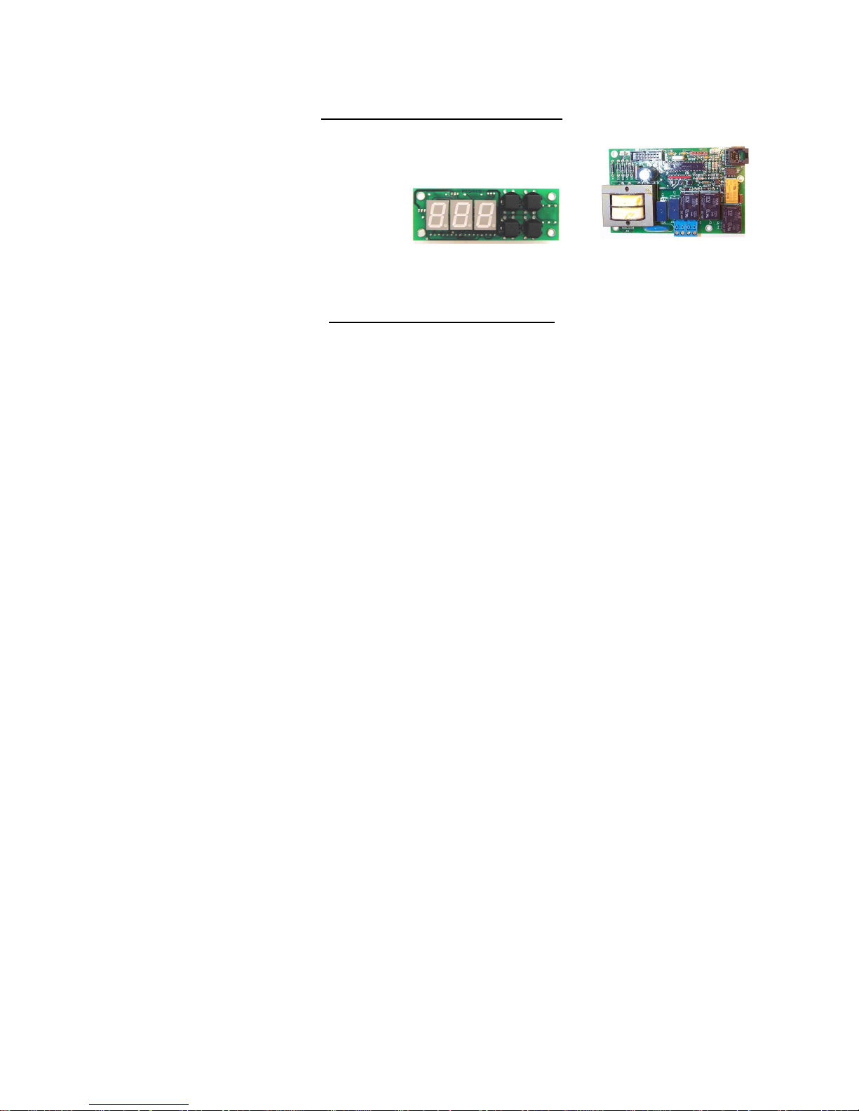
CONTROLLER DESCRIPTION
CONTROL BOARD AND DISPLAY
The control board supplies all the necessary
function for heater operation. These include
control temperature, hi-limit cut-out, low water
detection, and leak detection.
CONTROLLER OPERATION
NOTE: All controller variables come preset from the factory to include a preset temperature of 185°F.
1. To turn unit on or off:
a. Press the ON/OFF button on the display module.
b. Note that the controller will resume its last mode of operation if power is disconnected.
2. To change setpoint temperature (the temperature is fully adjustable from 32° to 194°F (0°-90°C):
a. Press the UP and DOWN arrows simultaneously to enter setpoint change mode.
b. Press the UP or DOWN button to change the setpoint temperature.
c. Pressing and holding the UP or DOWN button will scroll through the setpoint temperature.
d. To leave setpoint change mode
i. Wait 5 seconds without pushing any buttons or press the UP and DOWN buttons
simultaneously.
3. To view the number of operational hours (the number of hours when a contactor is pulled in) and
software version:
a. Press the UP and DOWN arrows simultaneously to enter setpoint change mode.
b. Press the ON/OFF button.
c. Display will flash the software version (e.g. R14), HRS, followed by the hours in thousands
of hours, followed by the hours.
i. Example: r14, HrS, 123, 456; indicates software version R1.4 and 123,456 hours.
d. To leave operational hours mode
i. Wait 5 seconds without pushing any buttons or press the UP and DOWN buttons
simultaneously.
4. Configuration Menu. (NOTE: Configuration menu change should only be made by qualified
personnel).
a. To enter the configuration menu, press and hold the UP, DOWN, and ON/OFF buttons
simultaneously for 5 seconds.
b. To scroll through menu settings, press the ON/OFF button.
c. To make a change to a menu setting use either the UP or DOWN arrow.
d. Settings:
i. Relays – sets the number of magnetic contactors used in the heater.
1. r##, where ## is the number of magnetic contactors (01 or 02).
ii. Low water detection – sets the low water detection on or off.
1. LOn, for low water on. (Factory Default)
2. LOF, for low water off.
iii. Low water reset – sets the low water reset for either automatic or manual
1. LAU, for low water automatic reset. (Factory Default)
2. LAn, for low water manual reset.
2
Page 3

iv. Temperature units – sets the temperature units to either degrees Fahrenheit or
Celsius.
1. DEF, for degrees Fahrenheit. (Factory Default)
2. DEC, for degrees Celsius.
v. Differential – sets the number of degrees below setpoint that the heater will resume
heating after it has achieved setpoint.
1. d##, where ## is the differential in degrees (1 to 20). (Factory set at 02)
vi. Display – sets the display to either setpoint or actual temperature.
1. dSS, for display setpoint temperature. (Factory Default)
2. dSt, for display actual temperature.
e. To leave the configuration menu, wait 5 seconds without pushing any buttons or press the UP
and DOWN buttons simultaneously.
5. To reset any high-limit, no probe, or low water (when in manual reset mode) fault condition, press the
RESET button.
6. Display
a. By default the display will show the setpoint of the booster heater.
b. The decimal points on the display, as shown below, indicate that the controller is calling for a
contactor to pull in.
Setpoint
nd
Contactor
2
(if supplied)
1st Contactor
3
Page 4

WIRING OPTIONS
OPTIONAL REMOTE ALARM CONTACTS
1. If desired, the control board can be wired to a remote alarm to indicate a reset fault condition. These
fault conditions include over-temperature, no probe, and low water (when the configuration is set to
manual reset).
2. This alarm can be wired to the J4 connector on the control board as shown below. To facilitate this
installation, an optional adapter, Hubbell P/N PLUG ADAPTER J4, can be purchased to provide wire
connections.
J4 Connnector
Common
(NO)
(NC)
Note: Rating (resistive)
Max. Switching Power:
60W, 62.5VA
PLUG ADAPTER J4
FOR REMOTE ON/OFF CONTROL
To remotely control the On / Off operation of the heater, it is
recommended that a DPST switch or relay (by others) be used to break
both power legs (white and black wires) connected to the top two
terminals of the J5 connector on the control board. See diagram at
right.
Use a NC (Normally Closed) relay to turn the booster ON when energizing the relay
coil or to turn the booster OFF when de-energizing the relay coil.
Use a NO (Normally Open) relay to turn the booster OFF when energizing the relay
coil or to turn the booster ON when de-energizing the relay coil.
Wiring from Contactor,
Power Distribution Block,
or Transformer
Remote Rela y by Customer
Max. Switching Voltage:
220VDC, 250VAC
Max. Switching Current: 2A
Max. Carrying Current: 3A
Wiring by
Customer
1
2
3
4
Controller J5 Connector
4
Red Wire to
Contactor #2
Yellow Wire to
Contactor #1
Page 5

TROUBLESHOOTING
ERROR MESSAGES
1. Err, No, Prb
a. This message will flash when the controller does not detect that the probe is
connected to the control board. To clear this error reinsert the probe connector and
press RESET. If the error message does not clear, replace the probe assembly.
2. Err, too, hot, ### (where ### is the actual temperature of the water.)
a. This message will display if the temperature of the water exceed the high limit
temperature setpoint. To clear this error, wait until the temperature is below the
operating setpoint and press RESET. Note that the unit will not reset until the
indicated temperature is below 195°F. If this message continually occurs, follow
the troubleshooting flow chart for continuous over-temperature condition.
3. Err, No, H2O
a. This message will display when the water level in the tank has dropped below the
sensor probe. To clear this message, refill the tank. If the low water reset is set for
automatic, the error will clear. If the low water reset is set for manual, when the
tank is full press RESET. Check the heater and the piping for leaks. Check for
mineral buildup on the probe and clean as required. Check for continuity between
the yellow wire and ground. See diagram 2 on the following page.
4. Err, H2O, LEA
a. This message displays if the leak detection sensor determines there is water in the
base of the heater shell. To clear this message, remove the water from the leak
detection sensor. Check the unit and piping for leaks.
MISCELLANEOUS
1. If the display flashes when the unit is first turned on or turned on after maintenance,
check that the J5 terminal on the controller is engaging all four pins on the board.
2. Note that before replacing the control board, display, or probe, it is recommended that the
power supply to the booster heater be turned off at the main circuit breaker disconnect to
the booster heater to reset and clear the electronic controller.
CAUTION: Do not use plumber’s tape/Teflon tape/pipe dope when installing the probe. Tape
will prevent the low water detection system from operating properly and will cause false low
water errors. Lubricate O-ring prior to installation.
Tighten probe at the brass hex flats only. Use a 13/16” open ended socket or spark plug wrench.
Do not apply pressure, twist, or turn the black wire or the stainless steel jam nut, as this will
damage the probe.
5
Page 6

TROUBLESHOOTING FLOW CHARTS
No Hot Water
Continuous Low
Water
Temperature
Verify setpoint
Verify water inlet
pressure and
temperature
OK?
No
Correct fault
condition
Yes
Check for loose
wires and tighten
as necessary
contactor pull
Yes
Is the
display on?
Yes
Is there an
error
message?
No
Magnetic
in?
Yes OK?
See 'No Display'
No
Yes
Message section
No
Verifythat all wires
are installed and in
correct positions
No
(see wiring
flowchart
See Error
of this manual
OK?
diagrams)
208/240V
at contactor
Verify T1000
configuration
settings. Replace
control board, i f
needed
No
coil?
No
Yes
Replace contactor
Unit properly
sized?
No
Replace with
correctly sized unit
Diagram 1
Thermistor Resistance vs Temperature
(error ±3%)
70°F = 11883
80°F = 9299
90°F = 7334
100°F = 5828
110°F = 4664
120°F = 3758
130°F = 3048
140°F = 2488
150°F = 2043
160°F = 1687
170°F = 1400
180°F = 1169
190°F = 980
Correct amps
at elements?
Yes
Plug probe end into RJ45 pigtail
(not supplied). Check ohms
across terminal s 1 and 4
(see diagrams 1 & 2). Compare
this with the ohms the thermistor
should supply for the actual
temperature in the tank
Ω
Ω
Ω
Ω
Ω
Ω
Ω
Ω
Ω
Ω
Ω
Ω
Ω
Replace faulty
element
Do ohms
match?
No
Replace probe
Diagram 2
Blue
Yellow
Green
Red
Black
White
OK? Contact factoryNo No
OK?
Probe End RJ45 Pigtail
Yes
No
To verify that
there is water
1
in the tank
2
3
4
5
6
yellow(#2) and
check for
continuity
between
ground.
6
Page 7

Continuous
over-temperature
condition
Diagram 3
White
Black
Red
Yellow
For 1 contactor:
check voltage across 1 & 4
For 2 contactor:
check voltage across 1 & 3 and 1 & 4
1
2
3
4
J5
contactors pull out
208/240V across
terminals 1 & 2 of J5 on
the control board as
Plug probe end into RJ45 pigtail
(not supplied). Check ohms
across terminals 1and 4
(see diagrams 1 & 2). Compare
this with the ohms the t hermistor
should supply for the actual
temperature in the tank
Do
at setpoi nt?
No
Is there
shown in the
diagram 3?
Yes
Yes
zero amp draw when the
contactors drop out at
No
Replace cont actor
Is there
setpoint?
No
Do ohms
match?
No
Yes
Yes
Correct
temperature
setpoint?
No
Properly set
temperature
setpoint
Replace control
board
Are configuration
settings set properly,
Yes
per Section III, Para.
4?
Yes
Contact f actory
No
Any or all buttons
do not work, but
display is
operational.
Re-seat ribbon
cable from display
to control board
Verify that the
display is properly
seated to the base
and that the
buttons click when
pressed.
Replace digi tal
display
Replace control
board
No
No
No
OK?
OK?
OK?
Replace probe
Individual di splay
elements do not
work or unusual
characters are
displayed
OK?
Re-seat ribbon
cable from display
to control board. Be
sure ribon cable is
not reversed.
Replace digital
display
Replace control
board
OK?
No
OK?
No
7
Page 8

No Displa y
Is the circuit
breaker tripped at
source?
No
Is the circuit
breaker tripped
inside heater
(if supplied)?
No
Yes
Yes
Reset circuit
breaker
Reset circuit
breaker
Press ON/OFF
button on heater
Is correct voltage
measured at power
distribut ion block or line
side of contactor for
each phase?
Yes
Is there 480V at
the line side of the
transform er
(480V models only)?
Yes
Is there
208/240V at the load side
of the transformer
(480V models only)?
No
Check incoming
No
No Check wiring
No
Transformer
OK?
power
Replace
Contact factory
Diagram 4
208/240V
1
terminals 1 & 2 of J5 on
2
3
4
J5
8
Yes
Is there
208/240V across
the control
board? (see
diagram 4)
Yes
Re-seat ribbon
cable from control
board to display
No
Check wiring
OK?
Replace digital
display
No
OK?
Replace control
board
No
OK?No
Page 9

SERVICING
CONTROL BOARD
1. Disconnect power from unit.
2. Disconnect display cable, probe cable (J3), leak detection wire (J2), ground wire (J7), and
terminal block (J5) from the control board. NOTE: The terminal block (J5) is removable
from the control board. Grasp the terminal block on the ends and pull straight away from
the board.
Ground Wire (J7) Display Cable Leak Detection Wire (J2) Probe Cable (J3)
Power Wire (Common, White) Connector (J5)
Power Wire (Black) Wire to #2 Wire to #1 Contactor (yellow)
Contactor (red)
(only for two contactor operation)
3. Remove four (4) screws securing control board to panel.
4. Remove and replace control board.
5. Reconnect wires disconnected in step 2. NOTE: When reconnecting the ribbon cable be
sure to have the key on the cable align with the slot in the connector.
6. Connect power to unit.
9
Page 10

SENSOR PROBE
1. Disconnect power from unit.
2. Shut off incoming water supply.
3. Attach hose to drain connection.
4. Lift manual release lever on relief valve to let air into system or break union on outgoing
water line.
5. Drain water from tank.
6. Disconnect probe wire from control board. (See picture)
Probe connection (J3)
7. Remove probe from tank using a 13/16” slotted socket or 13/16” spark plug wrench to
accommodate the probe cable.
NOTE: Care should be taken not to pull or put excessive force on the cable to probe
connection.
8. Install new #115 Buna-N o-ring gasket and
install new probe. NOTE: Hubbell
recommends lubricating the o-ring with Parker
O-Lube prior to installation. WARNING: Do
not remove the jam nut. To replace the probe,
remove the entire probe assembly from the
tank.
Probe
9. Reconnect probe wire to control board.
10. Refill tank.
11. Check for leaks. Retighten as required.
12. Note that to resume operation the controller will need to be reset by pressing the
‘RESET’ button on the display.
CAUTION: Do not use plumber’s tape/Teflon tape/pipe dope when installing the probe. Tape
will prevent the low water detection system from operating properly and will cause false low
water errors. Lubricate O-ring prior to installation.
Tighten probe at the brass hex flats only. Use a 13/16” open ended socket or spark plug wrench.
Do not apply pressure, twist, or turn the black wire or the stainless steel jam nut, as this will
damage the probe.
10
 Loading...