

Page 1
INSTRUCTIONS
INSTALLATION, OPERATION and MAINTENANCE
CHANCE TYPE M3 DISTRIBUTION SWITCH
GENERAL
! W ARNING
▲
Read and understand these instructions before
installation or operation of this equipment. Competent
personnel who understand proper safety procedures
must select, install, and service this equipment. This
instruction guide is written for such personnel. This
guide is not a substitute for adequate training and
experience in safety procedures for this type of
equipment.
FOR
The A. B. Chance Type M3 disconnect switch is a
single-phase hookstick operated switch. It is for
manual switching of de-energized or parallel circuits
of overhead lines on an electrical distribution system.
The M3 switch has no current making or breaking
capacity. Design variations allow for applications as
an electrical distribution switch or as an electrical
station switch. A number of options (connectors,
captive hardware, by-pass studs, etc.) are available
to better fit the user’s needs.
Select a properly rated M3 switch for each installation
with consideration to continuous current, BIL, and
rated voltage. Should there be any concern on the use
of this M3 switch as rated, consult your supervisor
before installation.
Inspect the switch for damage or missing parts. If
damage from rough handling is evident, immediately
file a claim with the transportation company. Contact
the nearest Chance sales office for replacement parts.
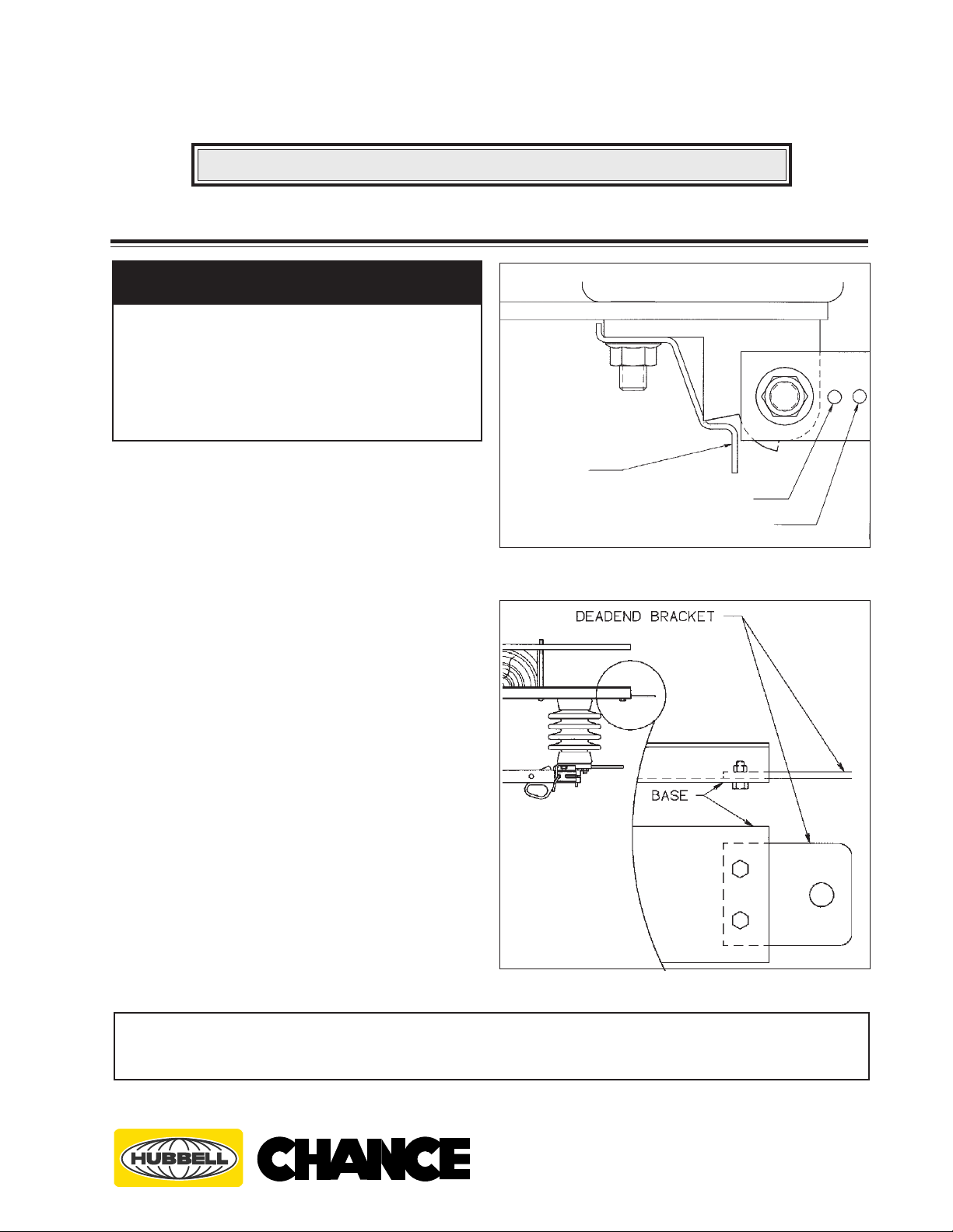
The M3 switch is supplied with a blade stop pin.
Before raising the switch for mounting, place this
pin in the proper hole to obtain either a 90° or 160°
(Figure 1) blade opening. Some switches may be
supplied with an open blade latch. The stop pin must
be in the 160° hole, as shown in Figure 1, to engage
the open blade latch. Attach deadending (Figure 2)
brackets (when supplied) to switch base with
hardware provided and tighten to about 20 footpounds.
OPEN LATCH
(OPTIONAL)
90° BLADE OPENING
160° BLADE OPENING
Figure 1
Figure 2
These instructions do not claim to cover all details or variations in equipment, nor to provide for all possible conditions to be met
with concerning installation, operation, or maintenance of this equipment. If further information is desired or if particular
problems are encountered which are not sufficiently covered in this guide, contact A. B. Chance Company.
NOTE: Because Hubbell has a policy of continuous product improvement, we reserve the right to change design and specifications without notice.
© Copyright 1996 Hubbell / Chance., 210 N. Allen, Centralia, MO 65240 Printed in USA
®
POWER SYSTEMS, INC.
®
Part No. P807-0198
Rev. B 6/96
Page 2
INSTALLATION
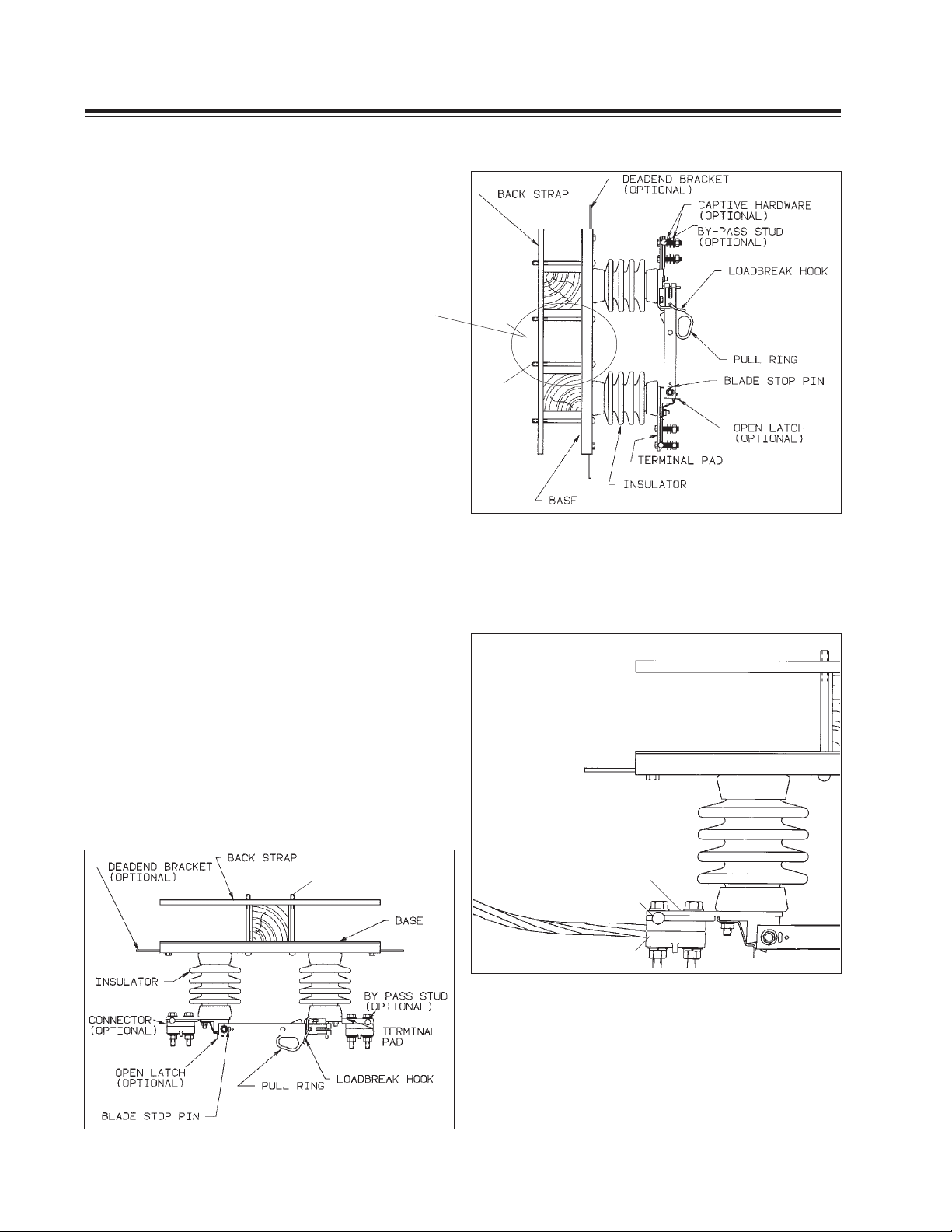
The distribution style M3 disconnect switch is
made for mounting to either a single or double
crossarm in an inverted (Figure 3) or vertical
position (Figure 4).
NOTE: Four bolts must be used to mount on a
double crossarm. Two bolts in center only
may cause over bending of backstrap or base.
Position the M3 switch on the crossarms using the
backstrap. Adjust the bolt heads in the switch
base slots as needed to closely fit the crossarms as
in Figures 3-4. Tighten mounting hardware to
about 12-15 foot-pounds.
Deadend conductors using your utility’s normal
practices.
Wire brush terminal pads and apply a coating of
oxidation inhibitor such as Chance z.l.n. (100 or
200).
If your switch is equipped with by-pass studs,
assemble between terminal pad and terminal. See
Figure 5.
(STANDARD)
NUTS &
WASHERS
THIS SIDE
ONLY
Figure 4
Vertical Mount
Wire brush connector mounting surfaces and
attach to terminal pads as shown in Figure 5 with
hardware facing away from insulators. Wire brush
electrical conductors and apply a coating of
oxidation inhibitor such as Chance z.l.n. (100 or
200) before inserting into connector. Tighten
connector hardware to about 30 foot-pounds (1/2"
hardware).
(STANDARD)
NUTS & WASHERS
THIS SIDE ONLY
TERMINAL PAD
BY PASS
STUD
TERMINAL
Figure 5
Figure 3 Inverted-Underhung
2
Part No. P807-0198
Rev. B 6/96
Page 3

OPERATION
! W ARNING
▲
Only qualified personnel should operate a disconnect
switch. Such personnel should wear appropriate
protective equipment such as rubber gloves, hard hat,
safety glasses, etc., in accordance with established
utility and safety practices.
To close the M3 disconnect switch, place the
hookstick in the pull ring on the blade and rotate the
blade to an intermediate position as shown in Figure
6. Look away from the switch. Quickly and firmly
drive the switch blade to the closed position. Carefully
remove the hookstick from the pull ring to avoid
opening the switch.
The M3 switch is properly closed when the blade hook
is fully engaged with the latch portion of the blade
stop as shown in Figure 7.
To open the M3 disconnect switch, place the hookstick
in the pull ring as shown in Figure 8.
Look away from the switch. Quickly and firmly pull
down and towards the hinge end of the switch at
about a 45° angle. Once the switch blade is open,
complete the blade travel to its stop position. Carefully
remove the hookstick from the pull ring.
! W ARNING
▲
Do not attempt to open a disconnect switch to interrupt
load current. An arc started by opening a disconnect
switch under load could cause injury to personnel or
damage to equipment.
All Chance M3 disconnect switches include loadbreak
hooks for use with a loadbreak tool. To open the
switch under load, use only an approved loadbreak
tool or device designed for use with switches. Follow
the instructions provided with such tools.
Figure 6
Figure 7
Figure 8
3
Part No. P807-0198
Rev. B 6/96
Page 4

MAINTENANCE
The Chance M3 disconnect switch should require
little maintenance. Following a program of periodic
inspection and maintenance will prolong the life of
the M3 switch.
• Operate the switch periodically to clean contact
surfaces and to free moving parts.
• Check for burned or pitted contacts and replace if
necessary.
• Check hinge bolt for looseness, and if loose, torque
to 40-in.-lb. and apply Loctite®-271 to bolt threads.
• Inspect all blade rivets for tightness and replace
blade if loose.
• Inspect mounting hardware and tighten as
needed (12 - 15- ft.lb.)
• Replace any broken or cracked insulators and
clean or replace if heavily contaminated.
For additional recommendations, refer to ANSI
C37.35 “IEEE Guide for the Application, Installation,
Operation, and Maintenance of High Voltage Air
Disconnecting and Load Interrupter Switches.”
®
®
POWER SYSTEMS, INC.
© Copyright 1996 Hubbell / Chance, 210 N. Allen, Centralia, MO 65240 Printed in USA
4
Part No. P807-0198
Rev. B 6/96
 Loading...