

Page 1

Hubbell Industrial Controls, Inc.
A subsidiary of Hubbell Incorporated
4301 Cheyenne Dr.
Archdale, NC 27263
Instruction Manual
Model LX3000
HUBBELL
Telephone (336) 434-2800
FAX (336) 434-2803
Diesel Engine
Fire Pump Controller
Publication No. 203
December 2003
Page 1 of 17
Page 2

Instruction Manual
LX3000 Diesel Fire Pump Controller
Introduction
Model LX3000 engine controllers, automatically control the operation of diesel engine driven centrifugal fire
pumps.
Installation
1. Consult the Controller nameplate to verify that the DC voltage and ground polarity matches the engine
battery. Also verify that the Controller AC power requirement matches available AC power.
2. Set the CONTROLLER ON / OFF - RESET SWITCH (inside controller) to the OFF position.
AUTION: Before drilling and punching holes in the cabinet for wiring connections, cover the
C
components inside the cabinet with a protective covering. Debris may cause shorts or
prevent operation of components.
3. 2 holes are pre-punched in the top left side of the cabinet for conduit entry.
4. Connect the water line to the INLET side of the solenoid valve located on the left side of the Controller.
Connect a drain line to the DRAIN side of the valve.
5. Connect Engine and Battery leads to TB1-1 through 12, connect the AC input to TB2-1 through 5, and
connect required alarm contacts, all per the Field Connection drawing supplied with the controller.
6. Connect remote start normally closed input contacts (if used) to TB1-13 and battery common.
7. Connect lockout/low suction normally open input contacts (if allowed by local jurisdiction) to TB1-14 and
battery common.
Start Up Instructions
1. Adjust the pressure switch set points to meet water system requirements. The adjustment switches are
located on the pressure switch control board, which is contained inside the pressure recorder enclosure.
Open the pressure recorder door and loosen the two chart plate screws. Swing the chart plate outwards to
gain access to the pressure switch control board. Set the STOP (HIGH) pressure setting on the upper three
switches. Set the START (LOW) pressure setting on the lower three switches.
The Green LED on the left (Excitation Voltage) indicates that the Gauge Transducer is connected and
power is available to the recorder. The middle LED (Relay Status) is bi-colored to indicate the status of the
output relay contacts. If this LED is green, pressure is above the Stop pressure. If the LED is red, pressure
is below the Start pressure. The red LED to the right (CAUTION) indicates the Start pressure is set higher
than the Stop pressure and needs to be corrected.
2. Set the recorder time using a coin or screwdriver to turn the chart hub clockwise to the time indicator on
the right side of the chart.
3. Remove the pen tip cover. If necessary, adjust the pen with the adjusting screw in the upper left corner of
the dial plate. The recorder accuracy is 2% of scale.
4. Adjust the weekly Test Timer for the correct timing settings as follows:
Set the time
1) Press the Reset button to clear the memory
Page 3

2) Press and hold the clock symbol key during entire time setting procedure.
a) Press the Day key to bring the actual day of the week into display.
b) Press the h button to set the hours and the m button to set the minutes. If the keys are depressed for
more than a second, the digits will advance rapidly.
c) Release the clock key when finished with the settings. The colon between the hours and minutes will
be flashing indicating the timer has started.
Programming
1) To set the Timer to start the engine once a week and run for a selected period of time.
Press Timer once (do not keep depressed) The display will show “1ON and “--:--“for the time.
a) Press h+ m+ to set the ON time.
b) Press Day to select the day of the week to run.
c) Press Timer key to enter program. The display will show 1”OFF”.
d) Program OFF command using steps b-d above.
e) Press the key to return to time od day display.
2) To review the programming
a) Press Timer key to review the individual commands as preprogrammed, at any time, be brought
consecutively into the display for revision or checking. Revisions are carried out by writing over the
existing programs using the steps outlined above.
5. Set Control Settings – also see attached drawing for locations of items 5 through 11.
a. Set the pressure switch start time delay (P/SWT DELAY SEC) on the Main Logic Board. The
adjustment range is 0 to 15 seconds in 1 second increments.
b. Set the AC Power Loss Delay Time on the Main Logic Board. The adjustment range is 0 to 90
seconds in 6 second increments.
c. Set the Auto Stop time switch (SW6). Settings are none, 15 minutes or 30 minutes.
d. Set the AC PowerLoss Start switch (SW4–2). Setting is on or off.
e. Set the AC Loss Audible Alarm switch (SW4-1). Setting is on or off.
6. Controller Testing
a. Verify pressure is above the Stop setting.
b. Turn CONTROLLER ON / OFF SWITCH to the ON position
Check the Test Timer to make sure that the Timer contacts are not about to close. Closure of the Timer
contacts during testing causes incorrect results.
Manual Start
a. Turn the AUTOMATIC / MANUAL SWITCH to the MANUAL position.
b. Operate the MANUAL CRANK # 1 switch or the MANUAL CRANK # 2 switch. Release as soon as the
engine starts.
Page 4

c. Turn the AUTOMATIC / MANUAL SWITCH to the AUTO position to stop the engine.
Automatic Engine Cranking in TEST
a. Disconnect engine wire from TB1-1 to prevent starting.
b. Press the TEST PUSHBUTTON on the weekly TEST TIMER. The solenoid valve opens to discharge
water, and the pressure switch contacts close to initiate cranking.
c. The controller will crank the engine on battery 1 for 15 second intervals followed by 15 second rest period.
It will then crank 15 seconds on battery 2, followed by 15 second rest period. This cycle is repeated 3
times, then cranking should will stop and the FAILURE TO START light comes on, the alarm sounds, and
the Common TROUBLE relay is energized.
d. Turn the CONTROLLER ON / OFF to the OFF position.
e. Reconnect the starter motor cable(s).
Automatic Pressure Start
a. With the AUTOMATIC / MANUAL SWITCH in the AUTO position, lower the system pressure below the
Start pressure.
b. The engine will start and run until pressure is above the Stop setting and the STOP button is pressed, or the
CONTROLLER ON / OFF SWITCH is turned to the OFF position, or the optional Automatic Stop Timer,
typically set for 15 or 30 minutes, stops the engine.
Battery Failure Test
a. With the AUTOMATIC / MANUAL SWITCH in the AUTO position, disconnect the battery wire on
TB1-6. The BATTERY NO.1 FAILURE LED should come on within two minutes. The alarm should
sound and the Common TROUBLE relay should energize. Reconnect the wire to TB1-6. Reset the alarm
by turning the CONTROLLER ON / OFF - RESET SWITCH from CONTROLLER ON to OFF - RESET
position then back to the CONTROLLER ON position.
b. Disconnect the battery wire on TB1-8. The BATTERY NO.2 FAILURE LED should come on within two
minutes. The alarm should sound and the Common TROUBLE relay should energize. Reconnect the wire
to TB1-8. Reset the alarm by turning the CONTROLLER ON / OFF - RESET SWITCH from
CONTROLLER ON to OFF - RESET position then back to the CONTROLLER ON position.
Charger Failure Test
a With the AUTOMATIC / MANUAL SWITCH in the AUTO position, disconnect the wire on TB1-6, and
disconnect the AC input to charger(s) no. 1. BATTERY NO.1 FAILURE & CHARGER 1 FAILURE light
should come on within two minutes. The alarm should sound and the Common TROUBLE relay should
energize. Reconnect the wire to TB1-6, reset the alarm by turning the CONTROLLER ON / OFF - RESET
SWITCH from CONTROLLER ON to OFF - RESET position then back to the CONTROLLER ON
position.
b Repeat the above for battery No. 2 & charger(s) no. 2, using the wire on TB1-8
Low Oil Pressure Test
a. With the AUTOMATIC / MANUAL SWITCH in the AUTOMATIC position, start the engine by
depressing the TEST PUSHBUTTON on the Weekly Timer.
Page 5

b. Wait 10 seconds for the Oil Pressure Delay interval to expire, then momentarily jumper TB1-4 to TB1-11.
The alarm will sound and the Common Trouble relay will energize. The LOW OIL PRESSURE LED will
come on and remain on after the engine stops.
c. Turn the CONTROLLLER ON / OFF - RESET SWITCH to the OFF - RESET position then back to the
CONTROLLER ON position to reset the LOW OIL PRESSURE Alarm.
High Water Temperature Test
a. WITH the AUTOMATIC / MANUAL SWITCH in the AUTOMATIC position, start the engine by
depressing the TEST PUSHBUTTON on the Weekly Timer.
b. Momentarily jumper the TB1-5 to TB1-11. The alarm will sound and the Common Trouble relay will
energized. The HIGH WATER TEMPERATURE LED will come on and remain on after the engine stops.
c. Turn the CONTROLLLER ON / OFF - RESET SWITCH to the OFF - RESET position then back to the
CONTROLLER ON position to reset the HIGH WATER TEMPERATURE Alarm.
Optional Remote Start
a. With the
AUTOMATIC / MANUAL SWITCH
in the
AUTO
position, open the remote start contacts, TB1-12
& 13, starting the engine.
b. Turn the CONTROLLER ON / OFF SWITCH to the OFF position to stop engine.
c. Close the remote start contacts.
Optional AC Power Failure Start (if enabled)
a. With the
AUTOMATIC / MANUAL SWITCH
to the
AUTO
position, disconnect the AC power supply to the
Controller.
b. After the pre-set time delay (0 to 90 seconds) the engine will start. The audible alarm should sound,
POWER LOSS
LED will come on, and both the Common
TROUBLE
AC POWER LOSS
and
relays will
energize.
c. Reconnect the AC power to reset the alarms.
d. Turn the
CONTROLLER ON / OFF - RESET SWITCH
to the
OFF - RESET
position to stop the engine.
End of Startup Testing
AC
Switches
1. Automatic/Manual – Selects automatic or manual mode.
2. Crank Battery 1 – Cranks the engine using battery 1.
3. Crank Battery 2 – Cranks the engine using battery 2.
4. Stop – Stops the engine in automatic if there are no start conditions and control switch is in “Auto”.
5. Normal/ Silence – Silences optional pump house alarm only. Standard alarms required NFPA 20 cannot be
silenced.
Page 6
Troubleshooting
Hazardous voltage
will shock, burn,
!
DANGER
or cause death.
Do not touch
until ALL power
is disconnected.
ARNING: Disconnect AC power to the Controller before servicing to prevent shock or accident
W
hazard.
Before troubleshooting, perform the following checks:
a. visual inspection for physical damage.
b. ensure that all switches are in the normal operating position.
c. ensure that the engine controls are set for operation.
d. ensure that all wiring connections are secure.
e. review the Startup procedure for proper operation to help determine if one of the system boards is faulty.
Page 7

Table 6-1 Troubleshooting
Condition Possible cause Checks Action
Engine does not crank
with MANUAL
START
Engine does not crank
using MANUAL
START - Battery No. 1
Batteries Voltmeters should read
at least 12.5 or 25 VDC
Check each battery in
bank for correct voltage
Battery circuits
MANUAL CRANK #1
switch
Check battery and
ground connections
Check battery voltage
Check battery cables
and connections
Check engine starter
cables and connections
Check battery voltage
while holding
MANUAL CRANK #1
switch
Check electrolyte
Test and recharge bad
battery(s)
Replace battery(s) with
good battery(s)
Clean and tighten
connections as
necessary
Clean and tighten
connections as
necessary
Refer to schematic
Use volt/ohm meter to
determine which
component is faulty
Engine does not crank
using MANUAL
START - Battery No. 2
If voltage checks indicate batteries and circuits OK then the engine starter or the pilot (or starting)
contactors are faulty.
MANUAL CRANK #2
switch
Check battery voltage
while holding
MANUAL CRANK #2
switch
Refer to schematic
Use volt/ohm meter to
determine which
component is faulty
Page 8

Table 6-1 Troubleshooting (Continued)
Condition Possible cause Checks Action
Engine cranks but does
not start
Engine continues to
crank after starting
AUTOMATIC /
MANUAL SWITCH
set to AUTO
Or
Test Mode Active
Water and fuel solenoid
circuits
Water and fuel solenoid
valves
Engine Crank Relay or
Main Logic Board
faulty
Engine Run signal
absent
Magnetic Pickup or
circuit faulty
Check battery voltage
Check WATER and
FUEL Relay
Check solenoids
Check fuel and water
lines
Check engine, fuel, fuel
filter
Check Crank 1 and
Crank 2 relays on
Engine Relay Board
Check Run LED on
Main Logic Board
Check for Pickup signal
at Main Logic Board
Clean and tighten
connections
Replace Engine Relay
Board
Replace Main Logic
Board
Replace solenoid(s) or
valve(s)
Complete necessary
engine repairs
Replace Engine Relay
Board.
Replace Main Logic
Board
Replace magnetic
Pickup
Engine does not crank
in TEST or AUTO
Engine cranks with
MANUAL START
Water and fuel
solenoids energized
Engine does not crank
in AUTO when water
pressure decreases
Engine cranks with
MANUAL START
Relay, or Main Logic
Board faulty
Pressure Switch, or
Main Logic Board
faulty
Check Crank 1 and
Crank 2 relays on
Engine Relay Board
Press P/S TEST button If cranking cycle begins
Replace Engine Relay
Board
Replace Main Logic
Board
refer to Appendix B
Pressure Switch /
Recorder
Replace Main Logic
Board
Table 6-1 Troubleshooting (Continued)
Page 9

Condition Possible cause Checks Action
Engine stops without
having to press STOP
button or before run
time is complete
Test Timer or Test
Pushbutton does not
start engine
AUTOMATIC /
MANUAL SWITCH in
AUTO
Engine starts after
pressure drop
Alarm does not sound,
Associated light not on
Water and Fuel
solenoid circuits and
valves, or
Main Logic Board
faulty
No power to solenoid
drain valve, or faulty
valve
Faulty Timer
Alarm faulty
LED Display faulty
Check Water and Fuel
Relay
Check Water Dump
Solenoid Relay
Check solenoid valve
Check Timer
program
Check alarm Replace alarm
Replace Engine Relay
Board
Replace Main Logic
Board
Replace Engine Relay
Board
Replace valve
Replace Timer
Replace LED Display
No BATTERY
FAILURE indication
Engine cranks
Main Logic Board
faulty
Power Sense Board
faulty
Main Logic Board
faulty
Table 6-1 Troubleshooting (Continued)
Check Power Sense
Board
Replace Main Logic
Board
Replace Power Sense
Board
Replace Main Logic
Board
Condition Possible cause Checks Action
Page 10

No HIGH ENGINE
TEMP indication
Engine overspeed does
not stop engine
No indication
Water temperature
switch
Faulty or mis-adjusted
magnetic sensor
Connect a jumper
across the water
temperature switch on
the engine
Start engine with
MANUAL START
switch
Verify that engine starts
and alarm sounds
Check sensor
installation
Replace water
temperature switch
Replace sensor
Indication but engine
does not stop under
overspeed simulation
Cranking and rest
periods greater than or
less than 15 ± 2 sec.
Engine cranks less than
six times
Engine continues to
crank in AUTO
position but does not
start
Controller does not
crank engine with good
battery
Engine cranking and
indication OK
Main Logic Board
faulty
Main Logic Board
faulty
Engine Relay Board
faulty
Main Logic Board
faulty
Check Main Logic
Board
Check Engine Relay
Board
Check Main Logic
Board
Replace Main Logic
Board
Replace Main Logic
Board
Replace Engine Relay
Board
Replace Main Logic
Board
Page 11

Table 6-1 Troubleshooting (Continued)
Condition Possible cause Checks Action
Engine does not crank
with Remote Start
Cranks when water
pressure decreases
Engine does not start
after AC power loss
Engine does not stop
with optional AUTO
STOP
Note
Remote switch faulty
Main Logic Board
faulty
Power Sense Board or
Main Logic Board
faulty
Another start condition
present
Main Logic Board
faulty
Check switch and
switch circuits
Check Main Logic
Board
Check Power Sense
Board
Check Main Logic
Board
Check controller start
conditions
Check Main Logic
Board
Repair circuits
Replace switch
Replace Main logic
Board
Replace Power Sense
Board
Replace Main Logic
Board
Replace Main Logic
Board
The above troubleshooting guide does not represent all possible conditions or problems. If the above
information can not resolve a problem, consult the factory or a local representative for further assistance.
Page 12

Page 13
Pressure Switch / Recorder
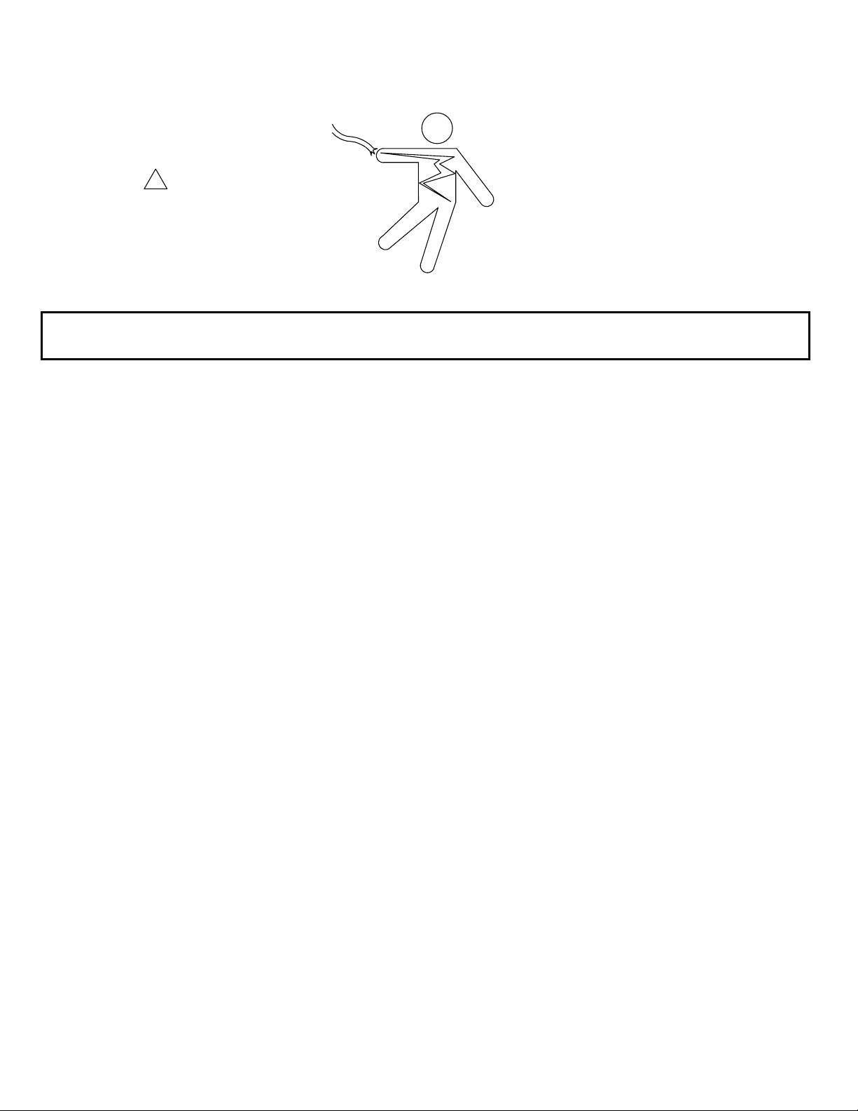
Changing the Chart Paper
First, locate the “change chart” button (#3) located in the upper left
corner of the recorder. Press and hold this button for approximately one
(1) second until the pen begins to move to the left of the chart. Wait
until the pen has moved completely off of the chart. To remove the
chart paper, unscrew (counter-clockwise) the “hub” knob at the center
of the chart. Remove the old chart paper and position the new one so
that the correct time coincides with the time line groove on the chart
plate. Refer to Figure 3 for the location of the time line groove on the
left side of the chart plate. Re-attach the chart “hub” knob and screw securely (by hand) against the chart.
Press the “change chart” button (#3) again for approximately one (1) second until the pen begins to move back
onto the chart paper.
Figure 1
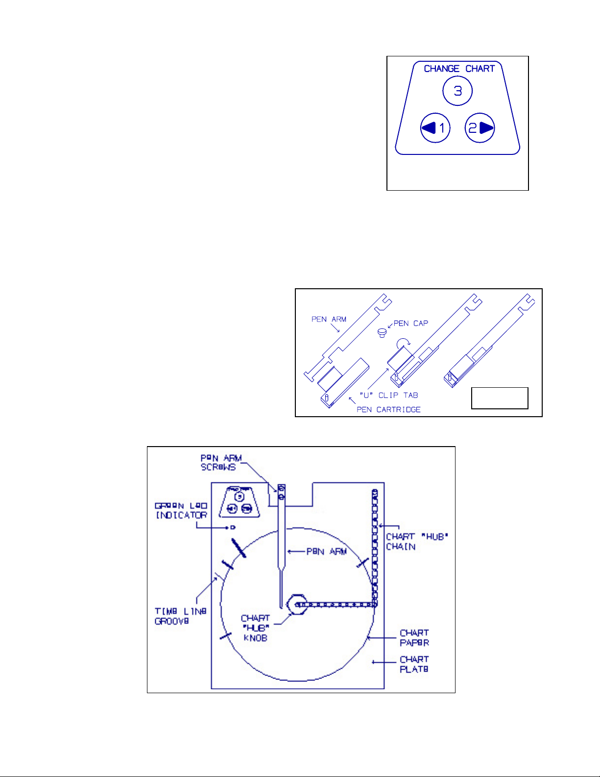
Pen replacement
Slide the used pen cartridge off the pen arm. Slide on new cartridge and remove tip cover.
To replace the pen, loosen the two screws that hold
the pen arm and the pen cartridge, and metal pen arm
be removed as an assembly. Refer to Figure 3 for
the location of the pen arm screws. Unsnap the
plastic “U” clip tab of the pen cartridge from the
metal pen arm (see Figure 2), remove and discard the
old pen cartridge. Replace the new cartridge by
opening the hinge and snapping it securely around
the metal pen arm.
Figure 2
Figure 3 - RECORDER ASSEMBLY
Page 14

Figure 4
(3)
Pressure Settings
SEE NOTE
Status LED’S
Stop Pressure
Start Pressure
Page 15

Battery Charger
Introduction
The Power Sense Board monitors the charging current and voltage of both chargers. LED’s indicate that the
chargers are supplying current output, that the battery / charger voltage is above 90%, and that AC Power is
available to power the chargers.
Specifications
LED Indication
READY, green
CHARGING, yellow
CHARGE CURRENT, green
On indicates float condition
On indicates charge in progress
Charging current greater than or equal to current indicated
ARNING: Lead acid batteries generate explosive gases during normal operation.
W
Precautions: Do not work alone.
Wear eye protection and protective clothing.
Have soap and water available in case of skin contact with acid.
If acid enters eye, immediately flush eyes with cold running water for ten minutes and
get medical attention.
If problems develop, check all connections and clean the battery terminal connections. Use the LED indicators
on the chargers and the LOBC as an aid to determine the cause of any potential problems. Return faulty
chargers to the factory.
AUTION: Always disconnect the AC power source before disconnecting the batteries when
C
performing maintenance.
Page 16

Troubleshooting Chart
Symptom Possible cause Solution
All charger LED’s off,
cabinet CHARGER FAILURE
indicating light on
Charge Current LED’s scroll,
cabinet CHARGER FAILURE
indicating light on
6
The charger LED’s scroll in order as follows: Charge Current LED’s 10 A to 2 A, Charging, Ready.
1) No AC power
2) Charger AC fuse blown
6
1) Battery connections
reversed,
2) Charger DC fuse blown
1) Check for 120 V Charger power
2) Hubbell recommends that the
charger be returned for repair
1) Check battery connections
2) Hubbell recommends that the
charger be returned for repair
Troubleshooting Chart (Continued)
Symptom Possible cause Solution
Charging LED blinking, Battery voltage high due to
Engine charging circuit
supplying charging voltage
above control charger value.
10 A Charge Current LED
flashing
Ready LED does not come on,
Charger stopped charging due
to high temperature
1) Battery capacity too high
Batteries do not charge fully
2) Excessive load on batteries
3) Short to ground
4) Battery terminals corroded
5) Battery has faulty cell
Troubleshoot engine charging
circuit
Allow charger time to cool
Improve ventilation in area
1) Check battery rating, must be
less than 200 Ah
2) Verify load is normal
3) Clear the short
4) Clean battery terminals
5) Check battery/Replace
Contact the local Hubbell representative to request additional information, parts, or drawings.
Page 17

Location and Description of Control Settings
 Loading...