

Hubbell ATU500CRP, ATD500CRP, ATU500C, ATD1000C, ATU1000C Installation Instructions Manual
...Page 1
H-MOSS® Adaptive Technology Sensors
ATD Series, ATU Series, ATP/AHP Series
Installation Instructions
DESCRIPTION
Hubbell Adaptive Technology (AT series) ceiling mount occupancy sensors are designed to reduce installation time and prevent
callbacks resulting from improper sensor adjustment. Hubbell AT series sensors study their environment and automatically
adjust the time delay and sensitivity to optimize the sensor’s performance for the specic application. Hubbell AT sensors must
be used in conjunction with a Hubbell control unit. The control units provide a 24VDC power supply for 1 to 3 sensors. The
correct control unit must be selected for the operating voltage of the application. Hubbell offers the following control units:
- CU300A(U)(M): 100-277V AC, 50/60 Hz.
- CU300HD: 100-277V AC, 50/60 Hz.
- CU347A: 347V AC, 60 Hz.
Each sensor is supplied with the hardware necessary for ceiling mounting.
FEATURES
• Adaptive Technology reduces installation time and prevents callbacks.
• Available in passive infrared (ATP/AHP series), ultrasonic (ATU series), dual technology - passive
infrared and ultrasonic (ATD series) models.
• Various models available for coverage areas from 500 to 2000 square feet.
• Isolated relay and photocell options provided on sensors with “RP” sufx.
• Visual motion indicators: ultrasonic-green LED, passive infrared-red LED.
• Sensor/ AAR* Capacity:
- CU300A(U)(M): 1 to 4 combined
- CU300HD: 1 to 6 combined
- CU347A: 1 to 3 combined
* Maximum of 2 AARs per control unit
PRE-INSTALLATION
1. NOTICE: For installation by a qualied electrician in accordance with national and local codes and
the following instructions.
2. NOTICE: For indoor use only.
3. CAUTION: RISK OF ELECTRIC SHOCK. Disconnect power before installing. Never wire
energized electrical components.
4. CAUTION: USE COPPER CONDUCTORS ONLY.
5. Check to see that the device’s rating is suitable for the application.
6.
When installing the Hubbell AT Series sensors, observe the maximum rated capacity of
the associated control unit:
- CU300A(U)(M): 15A Incandescent (1800W Tungsten) at 120V AC, 60 Hz.
20A Ballast (2400W Fluorescent) at 120V AC, 60 Hz.
20A Ballast (5540W Fluorescent) at 277V AC, 60 Hz.
- CU300HD: 20A, 120V AC Incandescent. 20A 120V AC or 277V AC Ballast.
Motor loads; 1 HP @ 120V AC, 2 HP @ 240/277V AC.
- CU347A: 15A Ballast (5205W) at 347V AC, 60 Hz.
7. NOTICE: Do not install if any damage to product is noted.
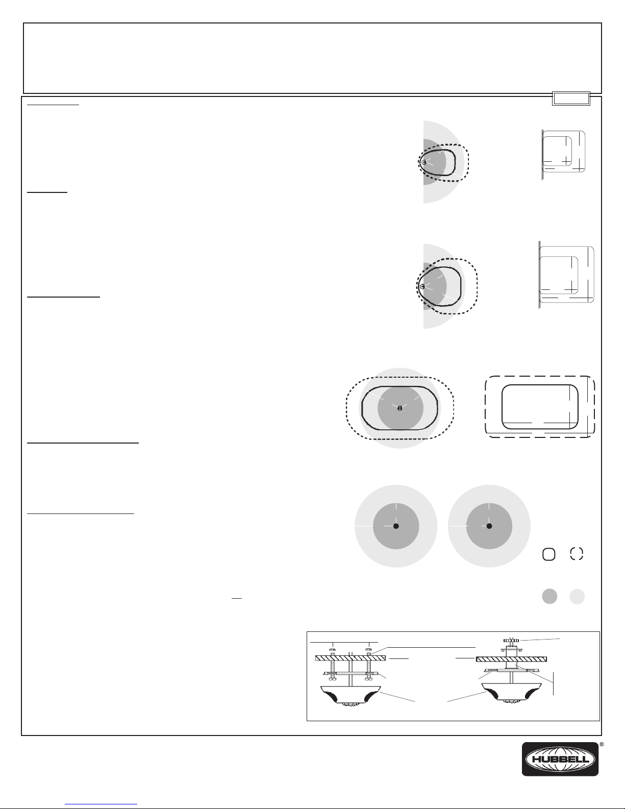
COVERAGE AND PLACEMENT
The patterns of coverage for the AT sensors are provided at right.
• Mounting ceiling height: 8 to 12 feet.
•
The sensors must be mounted at least 4’ from HVAC vents to avoid air current interference.
•
For interior use only. These sensors should NOT be installed in damp locations such as near
a shower or steam source, in wet locations, or where exposed to rain unless PIR sensors
are used combined with ACIPE (NEMA 4X Enclosure) for outdoor and damp locations.
• Do NOT install in view of strong direct or reected light sources.
INSTALLATION OF SENSORS
1. Disconnect Power.
2. Install CU series control units and, if applicable, AAR Add-A-Relay. See installation
instructions for these products.
3. Mount the sensor. The sensor must be mounted on the ceiling for proper operation. An
arrow is molded into the cover plate of the sensor. This should be used as a general
guideline to the direction of the coverage pattern. Fine tuning will be explained later.
Mounting options:
• For hard ceilings: Mount to a junction box.
•
For false ceilings: Attach the cover plate by either using machine screws and punching a small
hole through the ceiling tile for the sensor wires (Figure A, below) OR using the threaded
mounting post then running the sensor wires through the center of the post, (Figure B, below).
4. Attach the sensor to the cover plate by aligning the keys in the cover plate with those in the
sensor housing. Rotate the sensor housing until proper orientation is achieved.
5.
Using 3 conductor low voltage cable (18 to 22 AWG Type CL2, CL2P, CL2PR or CMR
as appropriate), connect the sensor and accessories to the control unit. Low voltage
wiring should not exceed 250 feet from the control unit to the last sensor. See control
unit installation instructions for wiring diagram.
6.
Insulate all exposed leads with Listed/Certied electrical tape or twist-on connectors
(wire nuts).
7. Restore the power to the control unit.
8.
Conrm the correct coverage by simulating motion in the coverage area which will be typical for
the application. If the desired coverage is not achieved, relocate the sensor to produce the desired
coverage. Test the sensor. To locate the test knob, remove the lens retainer and lens. Turn the black
timer knob fully counterclockwise from any clockwise position. Replace lens and retainer. The lights will
now turn off 8 seconds after motion stops. Reset timer for application. When installing sensors which
use passive infrared detection, the coverage pattern can be modied through the use of a lens mask.
Wiring Device-Kellems
Hubbell Incorporated (Delaware)
Shelton, CT 06484
1-800-288-6000
www.hubbell-wiring.com
PD1463 (PAGE 1) 11/13
nuts (tighten by hand)
0 5 10 15 20 25 30 35 40 45 50 55 60
0
5
10
15
20
25
30
35
40
45
•
Fig. A
0 5 10 15 20 25 30 35
0
5
10
15
20
25
30
35
40
45
12’
•
22’
•
ATD500C
ATD500CRP
0 5 10 15 20 25 30 35
0
5
10
15
20
25
30
35
40
45
•
22’
12’
•
12’
22’
•
ATD1000C
ATD1000CRP
•
ATD2000C
ATD2000CRP
•
12’
22’
ATP1500C
ATP1500CRP
•
ATP600C
ATP600CRP
13.5’
AHP1500CRP
6-32 machine screws (2)
ceiling tile
twist-lock cover plate
sensor
Caution: Attach wire nuts above ceiling tile
•
6.5’
Fig. B
17’
ATU500C
ATU500CRP
23’
ATU1000C
ATU1000CRP
45’
64’
ATU2000C
ATU2000CRP
ULTRASONIC
Minor
Motion
INFRARED
Minor
Motion
(tighten by hand)
English
17’
23’
23’
23’
32’
22’
Major
Motion
Major
Motion
nut
threaded
mounting
post
32’
32’
Page 2

MASKING THE INFRARED LENS (for ATD and ATP/AHP series sensors only)
This procedure is only required for applications where the passive infrared coverage pattern must be modied to prevent the pattern from extending out of
doorways into corridors. Three masks are provided with the sensors (one way sensors include 2 masks). Select the correct mask for the application based on
the descriptions below.
Using the Conference Room Mask
Using the 180º Mask
Using the Cutout Mask
0 5 10 15 20 25 30 35 40 45
0
5
10
15
20
25
30
This mask is used
when a Hubbell-DT is
mounted in the center
35
40
45
of a long rectangular
room (i.e. conference rooms). The mask provides a more
rectangular infrared pattern and prevents any spillage out
doorways at the sides of the room.
The 180º mask is best
suited for an overthe-door installation.
When the sensor is
installed inside the threshold of a doorway, you must
prevent the infrared coverage from spilling into the
adjacent corridor. New infrared pattern shown above.
0 5 10 15 20 25 30 35 40 45
0
5
10
15
20
25
30
35
40
45
0 5 10 15 20 25 30 35 40 45
0
5
10
15
20
This mask is scored on
the inside so it is easy
to achieve the perfect
mask for any application.
25
30
35
40
45
Simply trim away the
sections where coverage is necessary and leave the
portions where you want to prevent coverage. Lines on the
coverage pattern above represent the scores in the mask.
To install the selected lens, remove the lens retainer ring and lens. Insert the mask behind the lens. Be
certain to orient the mask properly to achieve the desired results. Replace the lens and lens retainer.
AMBIENT LIGHT LEVEL CONTROL OPTION (for models followed by RP sufx only)
The sensor is factory preset to turn the lights on regardless of the ambient light (natural light) level. Setting the ambient light level control will prevent the lights
from turning on when the ambient light is above the set level. The ambient light must be at the desired level to properly set this feature. To set the ambient light
level control:
1. Turn the black timer knob fully counter clockwise to the 8 second test mode.
2. Adjust the blue photocell knob fully clockwise. This will keep the lights off regardless of the ambient light.
3. Leave the sensor’s coverage area. The lights should turn off after about 8 seconds.
4. When the lights turn off, re-enter the area.
5. Slowly turn the blue photocell knob counterclockwise until the lights turn on.
The sensor is now set to prevent the lights from turning on when the ambient light level is above the set threshold.
ISOLATED RELAY OPTION (for models followed by RP sufx only)
The isolated relay can be used to interface the sensor with an auxiliary system. Normally open and normally closed contacts are available. For normally open
contacts, utilize the yellow/white and blue/white wires. For normally closed contacts, utilize the black/white and blue/white wires.
SENSOR CONTROLS & MODIFICATIONS
Hubbell Adaptive Technology sensors are designed to optimize performance by automatically adjusting the sensitivity and time delay to meet the application.
The sensor controls can be modied for custom operation. The modication options are outlined below.
Purpose Off On
B
Bank A DIP
Switches
Ultrasonic
Sensitivity (Red)
Timer
(Black)
Ultrasonic
Sensitivity
(Green)
Daylight Leveling
(Blue) Off
Bank B DIP
Switches
Bank
1
2
3
4
off on
Bank
1
2
3
4
off on
Strong airow Normal or very low Strong airow present
Compensator airow
Over Doorway Mounting Sensor mounted away Sensor mounted over
from door doorway
Automatic/Manual Timer Timer set automatically Manual timer setting
Sensitivity Adjust OFF = Auto ON = Manual
Purpose Off On
A
Manual Override Full automatic operation Manual lights on
Threshold Auto Threshold Adjust High Sensitivity
Motion Indicator Override LED ash when presence Disable LED lights
is detected
Reset learned settings Normal Toggle On and Off
Knob Color:
Control
Green:
Ultrasonic
Sensitivity
Red:
Infrared
Sensitivity
Black:
Timer
Blue:
Daylight
Leveling
Function
Sets the ultrasonic range Sensor analyzes room
Sets the infrared range Same as above Room (surface) temp.
Sets the length of time
lights will remain on after
last motion is sensed
Sets level of daylight
needed to prevent the lights
from turning on
**When a function is set to “Automatic Operation”, the initial setting is determined by the position of the knob, CCW is counter-clockwise, CW is clockwise
PD1463 (PAGE 2) 11/13
Automatic Operation
and sets sensitivity to
optimal setting
Timer setting generally
increased during learning
period, then decreases to
minimize “ON” time
No automatic operation N/A Linear range setting
Conditions Analyzed in
Automatic Operation
Air currents
False-on occurrences
False-off occurrences
Lens dirt
Signal-to-noise ratio
False-off occurrences
Error free operation decreases the timer setting
Knob Setting Under
Manual Operation**
Linear range setting
Full CCW = min (off)
Full CW = max range
Same as above 75%
Linear range setting
Full CCW = min (8 sec.)
Full CW = max (40 min)
Full CCW = min daylight
Full CW = max (off)
Recommended
Manual Setting
50%
33%
10 min.
Off
unless
used
Page 3

Capteurs à temporisation adaptable H-MOSS
Série ATD, Série ATU, Série ATP/AHP
Directives de montage
DESCRIPTION
Les capteurs de mouvement à temporisation adaptable de Hubbell (série AT), à monter au plafond, ont été conçus en vue
de réduire le temps de montage et d’éliminer les appels de service suite à un mauvais réglage du capteur. Les capteurs de la
série AT de Hubbell étudient l’environnement et règlent automatiquement la temporisation et la sensibilité en vue d’optimiser
le rendement du capteur pour l’application spécique. Les capteurs AT de Hubbell doivent être utilisés conjointement avec un
module de commande Hubbell. Le module de commande procure une alimentation de 24 V CC pour 1 à 3 capteurs et doit
être choisi en fonction de la tension du circuit à commander. Hubbell offre les modules de commande suivants:
- CU300A(U)(M): 100-277 V ca, 50/60 Hz. - CU347A: 347 V ca, 60 Hz.
- CU300HD: 100-277 V ca, 50/60 Hz.
Chaque capteur est fourni avec les accessoires nécessaires pour le montage au plafond.
CARACTÉRISTIQUES
• La technologie d’adaptation réduit le temps de montage et élimine les appels de service.
• Différents modèles de capteurs sont disponibles: à infrarouges passifs (série ATP/AHP), ultrasoniques
(série ATU), double technologie à infrarouges passifs et ultrasoniques (série ATD).
• Divers modèles sont disponibles pour couvrir des zones de 46 m2 à 186 m2.
•
Les capteurs dont le numéro de référence est accompagné du sufxe «RP» sont munis d’un relais isolé et d’une cellule photoélectrique.
• Indicateurs de mouvement visuels: DEL verte, ultrasoniques; DEL rouge, infrarouges passifs.
• Capacité du capteur/AAR*:
- CU300A(U)(M): 1 à 4 combinés
- CU300HD: 1 à 6 combinés
- CU347A: 1 à 3 combinés
*Maximum de 2 AARs par unité de commande
PRÉPARATION AU MONTAGE
1. AVIS - Doit être installé par un électricien qualié conformément aux codes de l’électricité nationaux et
locaux et selon les directives suivantes.
2. AVIS - Pour usage intérieur seulement.
3. ATTENTION - RISQUE DE CHOC ÉLECTRIQUE. Débrancher le circuit avant de procéder au
montage. Ne jamais câbler des composants électriques dans un circuit sous tension.
4. ATTENTION - EMPLOYER UNIQUEMENT DES CONDUCTEURS EN CUIVRE.
5. S’assurer que les caractéristiques nominales de ce dispositif conviennent à l’application.
6. Lors du montage, respecter les valeurs maximum assignées:
- CU300A(U)(M): 15 A, incandescent (1800 W tungstène) à 120 V ca, 60 Hz.
20 A, ballast (2400 W uorescent) à 120 V ca, 60 Hz.
20 A, ballast (5540 W uorescent) à 277 V ca, 60 Hz.
- CU300HD: 20 A, 120 V ca incandescent. 20 A 120 V ca ou 277 V ca ballast.
Charges de moteur; 1 HP à 120 V ca, 2 HP à 240/277 V ca.
- CU347A: 15 A, ballast (5205 W) à 347 V ca, 60 Hz.
7. AVIS - Ne pas installer si des dommages au module sont observés.
POSITIONNEMENT ET PORTÉE
La portée des capteurs AT est illustrée à droite.
• Hauteur de montage au plafond: 2,4 à 3,7 mètres.
• Les capteurs doivent être montés à au moins 1,20 m des bouches de chauffage et de
ventilation an d’éviter l’interférence causée par les courants d’air.
• Pour usage intérieur seulement.
•
Pour l’intérieur seulement. Ces capteurs NE doivent PAS être installés dans des endroits humides comme près de
douches ou de sources de vapeur, dans des endroits mouillés ou exposés à la pluie sauf si les capteurs PIR sont
utilisés conjointement avec des ACIPE (enveloppe NEMA 4X) convenant à l’extérieur et des endroits humides.
• NE PAS monter le capteur face à une source de lumière intense directe ou rééchie.
MONTAGE DU CAPTEUR
1. Débrancher le circuit.
2.
Installer les modules de commande de la série CU et, si nécessaire, les relais Add-A-Relay AAR.
Consulter les directives de montage de ces dispositifs.
3.
Monter le capteur. Le capteur doit être monté au plafond pour assurer son bon fonctionnement. La
èche gravée sur le couvercle du capteur indique la direction générale de la portée. Les directives
pour le réglage plus précis sont données plus loin.
Options de montage :
• pour plafond dur : monter sur une boîte de dérivation
•
pour faux plafond : xer la plaque couvercle en utilisant les vis et en perçant un petit trou
dans la tuile du plafond pour passer les ls du capteur (gure A) OU en utilisant la tige de
montage letée et en passant les ls du capteur dans le centre de la tige (gure B).
4.
Fixer le capteur à la platine couvercle en alignant les encoches du couvercle sur celles du boîtier
du capteur. Faire tourner le boîtier du capteur jusqu’à l’orientation voulue.
5.
Au moyen d’un câble basse tension à 3 conducteurs (de 18 à 22 AWG, type CL2,
CL2P, CL2PR ou CMR selon le cas), raccorder le capteur et les accessoires au
module de commande. La longueur du câblage basse tension séparant l’unité
de commande du dernier capteur ne doit pas excéder 76,2 mètres. Consulter les
directives du module de commande pour le diagramme de câblage.
6.
Isoler tous les conducteurs découverts au moyen de ruban isolant ou de raccords
à torsader homologués.
7. Remettre le module de commande sous tension.
8.
Vérier l’exactitude de couverture en simulant des niveaux de mouvement dans la zone de
couverture typique pour l’application. Si la couverture désirée n’est pas atteinte, déplacer le capteur
pour obtenir la couverture voulue. Pour atteindre le bouton de test, enlever l’anneau de retenue
de la lentille et la lentille. Tourner le bouton de temporisation noir à fond dans le sens contraire des aiguilles d’une montre. Remettre la lentille et l’anneau de retenue en place. Les lumières s’éteindront 8
secondes après l’arrêt de mouvement. Régler la temporisation selon les besoins. Si des capteurs à infrarouges passifs sont installés, on peut, à l’aide d’un masque, modier le patron de couverture.
Wiring Device-Kellems
Hubbell Incorporated (Delaware)
Shelton, CT 06484
1-800-288-6000
www.hubbell-wiring.com
PD1463 (PAGE 1) 11/13
écrous (serrer à la main)
10
12
14
0
2
4
6
8
10
12
14
0 2 4 6 8 10 12 14 16 18
0
2
•
4
6
8
10
12
14
6,7 m
ATD2000C
ATD2000CRP
•
3,7
6,7
•
ATP1500C
ATP1500CRP
AHP1500CRP
vis 6-32 (2)
plafond
platine couvercle
capteur
Attention: établir les raccordements
Fig. A
au-dessus du plafond
0 2 4 6 8 10
0
2
4
6
8
3,7 m
6,7 m
•
ATD500C
ATD500CRP
0 2 4 6 8 10
•
3,7 m
6,7 m
•
3,7 m
•
•
•
ATD1000C
ATD1000CRP
•
2
4,1
ATP600C
ATP600CRP
Fig. B
5,2 m
ATU500C
ATU500CRP
7 m
ATU1000C
ATU1000CRP
13,7 m
19,5 m
ATU2000C
ATU2000CRP
ULTRASONIQUE
Mouvement
Mineur
INFRAROUGE
Mouvement
Mineur
écrou
(serrer à la main)
tige de
suspension
filetée
MD
Français
7 m
5,2 m
7 m
7,m
9,8 m
6,7 m
Mouvement
Majeur
Mouvement
Majeur
9,8 m
6,7 m
Page 4

MASQUAGE DE LA LENTILLE À INFRAROUGES (pour les capteurs ATD et ATP/AHP uniquement)
Cette procédure n’est requise que pour les applications où le patron de couverture à infrarouges passifs doit être modié pour éviter qu’il ne s’étende au-delà des
ouvertures de porte jusqu’aux couloirs. Trois masques sont fournis avec les capteurs (le capteur unidirectionnel inclut 2 masques). Choisir le masque approprié à
l’application en fonction des descriptions ci-dessous.
Utilisation du masque pour salle de
Utilisation du masque à 180º
Utilisation du masque à découper
conférence
0 2 4 6 8 10 12 14
0
2
4
6
8
Ce masque est
utilisé pour le
montage du
10
12
14
Hubbell-DT au
centre d’une
longue salle rectangulaire (salle de conférence). Le
masque offre un patron de couverture à infrarouges
rectangulaire et empêche la dispersion vers les
ouvertures de portes sur les côtés de la salle.
Le masque à 180º
convient parfaitement
pour un montage
au-dessus de la
porte. Lorsque le
capteur est monté à l’intérieur du seuil de la porte,
il faut empêcher la dispersion de la couverture à
infrarouges vers le couloir adjacent. La nouvelle
couverture à infrarouges est illustrée ci-haut.
0 2 4 6 8 10 12 14
0
2
4
6
8
10
12
14
0 2 4 6 8 10 12 14
0
2
4
6
Le masque comporte
des rainures sur la face
interne pour pouvoir
facilement l’adapter
8
10
12
14
à n’importe quelle
application. Il suft
simplement de découper les sections où la couverture est
désirée et de laisser en place les parties ne nécessitant
pas de couverture. Les lignes sur le patron de couverture
ci-haut représentent les rainures sur le masque.
Pour monter la lentille choisie, enlever l’anneau de retenue de la lentille et la lentille. Insérer le masque à l’arrière de la lentille.
S’assurer de donner l’orientation adéquate au masque pour obtenir le résultat souhaité. Replacer la lentille et son anneau de retenue.
OPTION DE RÉGLAGE EN FONCTION DU NIVEAU DE LUMIÈRE AMBIANTE (uniquement pour les modèles dont le numéro de référence comporte le sufxe RP)
Le capteur est réglé en usine pour allumer les lumières quel que soit le niveau de lumière ambiante (lumière naturelle). Le réglage du seuil de lumière ambiante
empêche les lumières de s’allumer lorsque le niveau de lumière ambiante dépasse le seuil établi. La lumière ambiante doit être au niveau désiré pour pouvoir effectuer
ce réglage de façon adéquate. Pour régler la commande du seuil de lumière ambiante :
1. Tourner le bouton noir de temporisation dans le sens contraire des aiguilles d’une montre jusqu’au mode de test de 8 secondes.
2.
Tourner le bouton bleu de la cellule photoélectrique à fond dans le sens horaire. Ce réglage maintiendra les lumières éteintes quel que soit le niveau de lumière ambiante.
3. Sortir de la zone de couverture du capteur. Les lumières devraient s’éteindre au bout de 8 secondes.
4. Une fois les lumières éteintes, revenir dans la zone.
5. Tourner lentement le bouton bleu de la cellule photoélectrique dans le sens contraire des aiguilles d’une montre jusqu’à ce que les lumières s’allument.
Le capteur est réglé pour empêcher les lumières de s’allumer lorsque le niveau de lumière ambiante est supérieur au seuil établi.
OPTION DE RELAIS ISOLÉ (uniquement pour les modèles dont le numéro de référence comporte le sufxe RP)
Le relais isolé peut être utilisé comme interface entre le capteur et un système auxiliaire. Des contacts normalement ouverts et normalement fermés sont disponibles.
Pour les contacts normalement ouverts, utiliser les ls jaune/blanc et bleu/blanc. Pour les contacts normalement fermés, utiliser les ls noir/blanc et bleu/blanc.
COMMANDES DU CAPTEUR ET MODIFICATIONS
Les capteurs à temporisation adaptable de Hubbell ont été conçus pour optimiser le rendement par le réglage automatique de la sensibilité et de la temporisation
appropriées à l’application. Les commandes du capteur peuvent être modiées en vue d’une exploitation sur mesure. Les options de modication sont décrites ci-
dessous.
Commutateurs DIP
Groupe A
Sensibilité
Infrarouges
(rouge)
Temporisation
(noir)
Couleur du
bouton :
Commande
Vert :
Sensibilité
ultrasonique
Rouge :
Sensibilité
infrarouge
Noir :
Temporisation
Bleu :
Niveau de la
lumière du jour
Fonction
Règle la portée
ultrasonique
Règle la portée infrarouge Le capteur analyse la pièce
Règle le temps pendant
lequel les lumières resteront
allumées après cessation du
mouvement
Règle le niveau de lumière du
jour requis pour empêcher les
lumières de s’allumer
Le capteur analyse la pièce
et règle la sensibilité au
point optimal
et règle la sensibilité au
point optimal
La temporisation est augmentée
pendant la période d’acquisition
et diminuée par
réduire le temps pendant lequel
les lumières restent allumées
Ne fonctionne pas
automatiquement
* Lorsqu’une fonction est en mode automatique, le réglage initial correspond à la position du bouton.
SCAM = sens contraire des aiguilles d’une montre. SAM = sens des aiguilles d’une montre.
PD1463 (PAGE 2) 11/13
Sensibilité
ultrasonique
(vert)
Niveau de
lumière du jour
(bleu) Off
Commutateurs DIP
Groupe B
Fonctionnement
automatique
la
suite pour
Groupe
1
2
3
4
off on
Groupe
1
2
3
4
off on
Conditions analysées en
mode automatique
Courants d’air
Faux allumages
Faux arrêts
Température ambiante
Lentille sale
Rapport signal/bruit
Faux arrêts
En opération normale,
le réglage de temporisation est réduit
Sans objet
Fonction Off On
Compensateur de Courant d’air normal Courant d’air fort
B
courant d’air fort ou faible présent
Montage au-dessus Capteur monté loin Capteur monté au-dessus
d’une porte d’une porte d’une porte
Temporisation Réglage automatique de Réglage manuel de
automatique / manuelle la temporisation la temporisation
Réglage de la sensibilité OFF = Automatique ON = Manuel
Fonction Off On
Annulation de priorité Fonctionnement Allumage manuel de
A
manuelle entièrement automatique l’éclairage
Point de consigne Réglage automatique Haute sensibilité
du point de consigne
Annulation de l’indicateur La DEL clignote à la La DEL est inactive
de mouvement detection de mouvement
Rappel des réglages Normal Commutation ON et OFF
acquis
Réglage du bouton en
mode manuel*
Réglage linéaire de la portée
SCAM à fond = min. (éteint)
SAM à fond = portée max.
Réglage linéaire de la portée
SCAM à fond = min. (éteint)
SAM à fond = portée max.
Réglage linéaire de la tempor.
SCAM à fond = min. (8 sec.)
SAM à fond = max. (40 min.)
Réglage linéaire lumière du jour
SCAM à fond = Lumière min.
SAM à fond = max. (hors service)
Réglage manuel
recommandé
50 %
75 %
33 %
10 min.
Off
sauf à
l’usage
Page 5

Detectores de tecnología adaptable H-MOSS
Serie ATD, Serie ATU, Serie ATP/AHP
Instrucciones de instalación
DESCRIPCIÓN
Los detectores de ocupación jados al techo de tecnología adaptable (Serie AT) están diseñados para reducir el tiempo de instalación y evitar las
demandas de servicio técnico resultantes de un ajuste incorrecto del detector. Los detectores de la serie AT de Hubbell estudian su ambiente y ajustan
automáticamente el retardo y la sensibilidad para optimizar el rendimiento del detector para cada aplicación especíca. Los detectores AT de Hubbell
deben usarse conjuntamente con unidades de control de Hubbell. Las unidades de control suministran energía de V=24 para 1 a 3 detectores. Debe
elegirse la unidad de control apropiada para la tensión de funcionamiento de la aplicación. Hubbell ofrece las siguientes unidades de control:
- CU300A(U)(M): 100-277 V~, 50/60 Hz. - CU347A: 347 V~, 60 Hz.
- CU300HD: 100-277 V~, 50/60 Hz.
Cada detector se provee con los accesorios necesarios para jarlo al techo.
CARACTERÍSTICAS
• La tecnología adaptable reduce el tiempo de instalación y evita las demandas de servicio técnico.
• Disponible en modelos con infrarrojos pasivos (serie ATP/AHP), ultrasonidos (serie ATU), y tecnología
doble: infrarrojos pasivos y ultrasonidos (serie ATD).
• Diversos modelos disponibles para áreas de cobertura de 45 a 185 m².
•
Con los detectores que llevan el sujo “RP”, se proveen opciones con relé y células fotoeléctricas aislados.
•
Indicadores visuales de movimientos: LED verde en los ultrasonidos, LED rojo en los infrarrojos pasivos.
• Capacidad del sensor/AAR*:
- CU300A(U)(M): 1 a 4 combinados
- CU300HD: 1 a 6 combinados
- CU347A: 1 a 3 combinados
* Máximo de 2 AARs por unidad de control
PREPARACIÓN PARA LA INSTALACIÓN
1. AVISO - Para ser instalado por un electricista calicado, de acuerdo con los códigos eléctricos
nacionales y locales y siguiendo estas instrucciones.
2. AVISO - Para uso interior únicamente
3. CUIDADO - RIESGO DE CHOQUE ELÉCTRICO. Desconectar la corriente antes de la instalación.
No conectar nunca componentes eléctricos en un circuito energizado.
4. CUIDADO - UTILIZAR SOLAMENTE CONDUCTORES DE COBRE.
5. Asegurarse de que las características nominales del dispositivo sean apropiadas para la aplicación.
6. Al instalar los detectores de la serie AT de Hubbell, respetar la capacidad nominal máxima del módulo de
control appropiado:
- CU300A(U)(M): Incandescente de 15 A (tungsteno de1800 W) a 120 V~, 60 Hz.
Balasto de 20 A (uorescente de 2400 W) a 120 V~, 60 Hz.
Balasto de 20 A (uorescente de 5540 W) a 277 V~, 60 Hz.
- CU300HD: 20 A, 120 V~, incandescente. 20 A, 120 V~ ó 277 V~, balasto.
Cargas de motor; 1 HP @ 120 V~, 2 HP a 240/277 V~.
- CU347A: Balasto de 15 A (5205 W) a 347 V~, 60 Hz.
7. AVISO - No instalar si se advierte un daño visible en el dispositivo.
COBERTURA Y COLOCACIÓN
A la derecha se indican los planos de cobertura de los detectores AT.
• Altura del cielorraso de montaje: 2,4 à 3,7 metros.
•
Los detectores deben jarse a 1,20 m, como mínimo, de equipos de ventilación para evitar la
interferencia de corrientes de aire.
•
Para uso en interiores únicamente. Estos sensores NO deben ser instalados en sitios húmedos tales como
cerca de duchas o fuentes de vapor, en lugares mojados, o donde estén expuestos a lluvia a menos que se
utilicen sensores PIR combinados con ACIPE (NEMA 4X caja) para exteriores o lugares húmedos.
• NO instalarlos frente a fuentes de luz intensa directa o reejada.
INSTALACIÓN DE LOS DETECTORES
1. Desconectar la corriente.
2. Instalar las unidades de control de la serie CU y, si corresponde, los relés Add-A-Relay
(AAR). Ver las instrucciones de instalación para estos productos.
3.
Montar el detector, que debe estar jado al techo para funcionar correctamente. En la placa de cobertura
del detector hay una echa moldeada, que debe usarse como guía general para la orientación del plano
de cobertura. Más adelante se explicará cómo sintonizarlo con precisión. Opciones de montaje:
• Para techos rígidos: Instalar una caja de derivación.
•
Para falsos cielorrasos: Fijar la placa de cobertura con tornillos para metales y perforando un pequeño
oricio a través del cielorraso para pasar los cables del detector (Figura A) O BIEN usando vástago de
suspensión roscado y pasando los cables del detector por el centro del vástago (Figura B).
4.
Fijar el detector a la placa de cobertura alineando las ranuras de la placa con las de la caja
del detector. Hacer girar la caja del detector hasta obtener la orientación apropiada.
5.
Usando un cable de baja tensión de 3 conductores (18 a 22 AWG de tipo CL2, CL2P, CL2PR o CMR,
según corresponda), conectar el detector y los accesorios a la unidad de control. Los alambres de
bajo voltaje no deben exceder 76,2 metros desde la unidad de control hasta el último sensor. Ver el
diagrama de cableado en las instrucciones de instalación del módulo de control.
6.
Aislar todos los conductores expuestos con cinta aislante o conectores de rosca homologados.
7. Restablecer la corriente en la unidad de control.
8.
Conrmar la cobertura correcta simulando los movimientos dentro del área cubierta que
serán típicos en la aplicación Si no se logra la cobertura deseada, colocar el detector
en otra posición para obtener la cobertura correcta. Ensayar el detector. Para encontrar
la perilla de ensayo, retirar el retén de la lente y la lente. Hacer girar la perilla negra del
temporizador a fondo en sentido contrario a las agujas del reloj desde cualquier posición
del dial. Volver a colocar la lente y el reten. Las luces se apagarán 8 segundos después
de haber cesado el movimiento. Volver a regular el temporizador para la aplicación.
Al instalar detectores de infrarrojos pasivos, el plano de cobertura se podrá modicar
aplicando una máscara en la lente.
Wiring Device-Kellems
Hubbell Incorporated (Delaware)
Shelton, CT 06484
1-800-288-6000
www.hubbell-wiring.com
PD1463 (PAGE 1) 11/13
tuercas (ajustar con la mano)
Fig. A
0
2
4
6
8
10
12
14
0
2
4
6
8
10
12
14
0 2 4 6 8 10 12 14 16 18
0
2
•
4
6
8
10
12
14
6,7 m
3,7 m
•
ATD2000C
ATD2000CRP
•
3,7
6,7
•
ATP1500C
ATP1500CRP
AHP1500CRP
tornillos 6-32 (2)
techo
placa de cobertura
detector
Cuidado: instalar los conectores de
rosca por encima del techo
0 2 4 6 8 10
•
3,7 m
6,7 m
•
ATD500C
ATD500CRP
0 2 4 6 8 10
•
3,7 m
6,7 m
•
ATD1000C
ATD1000CRP
•
2
4,1
•
ATP600C
ATP600CRP
ATU2000C
ATU2000CRP
Movimiento
Movimiento
(ajustar con la mano)
Fig. B
MR
Español
5,2 m
5,2 m
7 m
ATU500C
ATU500CRP
7 m
9,8 m
ATU1000C
ATU1000CRP
6,7 m
13,7 m
19,5 m
ULTRASÓNICO
Movimiento
Menor
INFRARROJOS
Menor
Mayor
Movimiento
Mayor
tuerca
vástago de
suspensión
roscado
7,m
7 m
9,8 m
6,7 m
Page 6

CÓMO ENMASCARAR LA LENTE DE LOS DETECTORES INFRARROJOS (únicamente para detectores de las series ATD y ATP/AHP)
Este procedimiento sólo se requiere para las aplicaciones en que el plano de cobertura con infrarrojos pasivos debe modicarse para evitar que se expanda a través de
las puertas hacia los pasillos. Con los detectores se proveen tres máscaras (los detectores unidireccionales incluyen 2 máscaras). Elegir la máscara apropiada para la
aplicación, a partir de las descripciones siguientes.
Para usar la máscara de sala de conferencias
Para usar la máscara de 180°
Para usar la máscara de recorte
0 2 4 6 8 10 12 14
0
2
4
6
8
Esta máscara se usa
cuando se monta un
Hubbell-DT en el
10
12
14
centro de una sala
rectangular larga (p. ej., una sala de conferencias).
La máscara proporciona un plano de infrarrojos más
rectangular y evita que la detección se expanda por
las puertas laterales de la sala.
La máscara de 180° es
la más apropiada para
una instalación sobre
la puerta. Cuando el
detector se instala hacia el interior del vano de
una puerta, se debe impedir que la cobertura de
infrarrojos se expanda al pasillo contiguo. A la
derecha se muestra el nuevo plano del infrarrojo.
0 2 4 6 8 10 12 14
0
2
4
6
8
10
12
14
0 2 4 6 8 10 12 14
0
2
4
6
Esta máscara lleva
muescas en su interior,
de modo que es fácil
lograr la máscara
8
10
12
14
perfecta para cualquier
aplicación. Simplemente
hay que desprender las secciones en que es necesaria la
cobertura y dejar las porciones en que se quiere evitar la
cobertura. Las líneas en el plano de cobertura a la derecha
representan los recortes en la máscara.
Para instalar la lente elegida, retirar el aro retén y la lente. Insertar la máscara detrás de la lente. Asegurarse de orientar
correctamente la máscara para lograr los resultados deseados. Volver a colocar la lente y su aro retén.
OPCIÓN DE CONTROL DEL NIVEL DE LUZ AMBIENTE (únicamente para los modelos que llevan el sujo RP)
El detector está regulado en fábrica para encender las luces, independientemente del nivel de luz ambiente (luz natural). La regulación del control del nivel de luz
ambiente evitará que las luces se enciendan cuando el nivel de luz ambiente sea superior al nivel prejado. La luz ambiente debe estar al nivel deseado para regular
correctamente este artefacto. Para regular el control del nivel de luz ambiente:
1. Girar la perilla negra del temporizador en sentido contrario a las agujas del reloj al máximo, hasta el modo test de 8 segundos.
2.
Ajustar la perilla azul de la célula fotoeléctrica al máximo en el sentido de las agujas del reloj. De este modo las luces se mantendrán apagadas, cualquiera sea la luz ambiente.
3. Salir del área de cobertura del detector. Las luces deberían apagarse después de 8 segundos.
4. Cuando las luces se apaguen, volver a entrar al área.
5. Girar lentamente la perilla azul de la célula fotoeléctrica en sentido contrario a las agujas del reloj, hasta que las luces se enciendan.
El detector ha quedado regulado para evitar que las luces se enciendan cuando el nivel de luz ambiente sea superior al umbral jado.
OPCIÓN CON RELÉ AISLADO (únicamente para modelos que lleven el sujo RP)
El relé aislado puede usarse para conectar el detector con un sistema auxiliar. Se ofrecen contactos normalmente abiertos y normalmente cerrados.
Para los contactos normalmente abiertos, utilizar los cables amarillo/blanco y azul/blanco.
Para los contactos normalmente cerrados, utilizar los cables negro/blanco y azul/blanco.
CONTROLES Y MODIFICACIONES DE LOS DETECTORES
Los detectores de tecnología adaptable de Hubbell están diseñados para optimizar su funcionamiento ajustando automáticamente la sensibilidad y el retardo del modo
que convenga a la aplicación.
Los controles del detector pueden modicarse para funcionar a medida de las necesidades. A continuación se exponen las opciones de modicación.
Finalidad Off On
Compensador de Corriente de aire Corriente de aire fuerte
B
corrientes de aire fuertes normal o muy baja presente
Montaje sobre Detector montado alejado Detector montado por
vano de puerta de la puerta encima de la puerta
Temporizador Temporizador regulado Reglaje manual
automático/manual automáticamente del temporizador
Ajuste de la sensibilidad OFF = Automático ON = Manual
Finalidad Off On
Anulación manual Funcionamiento Encendido manual
A
totalmente automático
Umbral Ajuste automático Alta sensibilidad
del umbral
Anulación indicador El LED guiña cuando se Inhabilita los LED
de movimientos detecta una presencia
Reajustar los reglajes Normal Encendido y apagado
adquiridos
Condiciones analizadas
en el funcionamiento
automático
Corrientes de aire
Encendidos falsos
Apagados falsos
Suciedad de la lente
Relación señal-ruido
Falsos apagados
El funcionamiento
sin error disminuye el
reglaje del temporizador
No se aplica Reglaje lineal de la cobertura
Reglaje de la perilla*
Funcionamiento manual
Reglaje lineal de la cobertura
CAR a fondo = mín (apag.)
SAR a fondo = cobertura máx.
Igual que el anterior
Reglaje lineal de la cobertura
CAR a fondo = mín (8 seg.)
SAR a fondo = máx (40 min.)
CAR a fondo = mín. luz diurna
SAR a fondo = máx. (apagado)
Reglaje manual
recomendado
50 %
75 %
33 %
10 min.
Off
salvo que
se use
Conmutadores DIP
grupo A
Sensibilidad
Infrarrojos (rojo)
Temporizador
(negro)
Colorde la
perilla:
Control
Verde:
Sensibilidad
ultrasónica
Rojo:
Sensibilidad
infrarrojos
Negro:
Temporiza-
Azul:
Nivel de luz
diurna
Finalidad
Regula la cobertura
ultrasonica
Regula la cobertura de
infrarrojos
Regula el tiempo que las
luces quedarán encendidas
después de detectar el último
movimiento
Regula el nivel de luz
diurna necesario para evitar
que las luces se enciendan
Sensibilidad
ultrasonidos
(verde)
Nivel de luz
diurna (azul)
Grupo
1
2
3
4
off on
apagado
Grupo
Conmutadores DIP
grupo B
Funcionamiento
automático
El detector analiza el local
y ja la sensibilidad para el
ajuste óptimo
Igual que el anterior Temperatura local
El reglaje del temporizador
aumenta durante el período de
aprendizaje, luego disminuye
hasta minimizar el tiempo
«encendido»
No funciona
automáticamente
1
2
3
4
off on
* Cuando una función se regula en “Funcionamiento automático”, el reglaje inicial está determinado por la posición de la perilla.
CAR signica en sentido contrario a las agujas del reloj, SAR en el sentido de las agujas del reloj.
0 2 4 6 8 10 12 14
0 5 10 15 20 25 30 35 40 45
PD1463 (PAGE 2) 11/13
 Loading...