

Page 1

300 Rigid Pavement Design
Table of Contents
300 Rigid Pavement Design ............................................... 300-1
300.1 Introduction ............................................................................... 300-1
300.2 Types of Concrete Pavement.................................................... 300-1
301 Design Parameters .............................................................. 300-2
301.1 Modulus of Rupture ................................................................... 300-2
301.2 Modulus of Elasticity ................................................................. 300-2
301.3 Load Transfer Coefficient .......................................................... 300-2
301.4 Composite Modulus of Subgrade Reaction ............................... 300-2
301.5 Loss of Support ......................................................................... 300-2
301.6 Effective Modulus of Subgrade Reaction .................................. 300-3
302 Thickness Determination .................................................... 300-3
302.1 Ramps and Interchanges .......................................................... 300-3
303 Jointing and Shoulder Considerations ............................. 300-3
303.1 Transverse Joints...................................................................... 300-3
303.2 Expansion and Pressure Relief Joints ...................................... 300-3
303.3 Longitudinal Joints .................................................................... 300-4
303.4 Intersection Jointing Details ...................................................... 300-4
303.5 Shoulder Considerations ........................................................... 300-4
303.6 Edge Course Design ................................................................. 300-5
304 Concrete Pavement Usage Guidelines .............................. 300-5
304.1 Item 451 Reinforced Concrete Pavement ................................. 300-5
304.2 Item 452 Non-Reinforced Concrete Pavement ......................... 300-5
304.3 Item 884 Warranty Concrete ..................................................... 300-5
304.4 Item 305 Concrete Base ........................................................... 300-5
304.5 Class of Concrete ..................................................................... 300-6
305 Warranty Concrete ............................................................... 300-6
306 Smoothness Specifications ................................................ 300-6
307 Composite Pavement .......................................................... 300-6
July 2014
Page 2

300 Rigid Pavement Design
307.1 Composite Pavement Design.................................................... 300-6
307.2 Composite Pavement Typical Section Design .......................... 300-7
307.3 Composite Pavement Warranty ................................................ 300-7
307.4 Composite Pavement Smoothness Specifications .................... 300-7
July 2014
Page 3

300 Rigid Pavement Design
300 Rigid Pavement Design
300.1 Introduction
Rigid pavements can be constructed with contraction joints or no joints, with dowels or without
dowels, and with reinforcing steel or without steel. For jointed concrete pavements, regardless of
whether reinforced or non-reinforced, the AASHTO/ODOT method of pavement design calculates the
same required thickness. The required thickness is a function of loading, material properties including
subgrade, and type of load transfer, if any. Alterations to rigid pavement material specifications, jointing
considerations, and mesh provisions to something other than those provided in ODOT's Construction and
Material Specifications (C&MS) or ODOT's Standard Construction Drawings may require adjustments to
the procedures described herein.
The Construction Inspection Manual of Procedures published by the Office of Construction
Administration contains additional information on rigid pavement and proper construction practices.
300.2 Types of Concrete Pavement
ODOT has two basic types of concrete pavement: reinforced and non-reinforced. There are
currently three different specifications for concrete pavement and one for concrete base. All of the
concrete specifications relate back to either reinforced or non-reinforced. The current specifications are:
Item 451 Reinforced Concrete Pavement, Item 452 Non-Reinforced Concrete Pavement, Item 884
Portland Cement Concrete Pavement (7 Year Warranty), and Item 305 Concrete Base. All of the
concrete pavements included in the C&MS and Supplemental Specifications are jointed. Continuously
reinforced concrete pavement is no longer used and the specification item has been removed from the
C&MS.
Item 451 Reinforced Concrete Pavement is the basic specification referred to by all other
concrete pavement specifications. Reinforced concrete contains steel wire mesh intended to tightly hold
together any cracks that occur. The steel mesh does not add any structural capacity and does not impact
the thickness design. A reinforced pavement is the same thickness as a non-reinforced one. The
reinforcing steel allows longer joint spacing with the expectation that mid-panel cracks will form but the
steel will hold them tightly together and not allow further deterioration. Hairline cracks (less than
approximately 1/8 inch (3 mm) wide) are common, even expected, in reinforced pavements and are little
cause for concern. Wider cracks likely mean the steel has failed and the cracks are going to deteriorate
and need repair. Throughout the 1950's, 60's, 70's, 80's, and early 90's ODOT built mainly reinforced
pavements.
Item 452 Non-Reinforced Concrete Pavement is nearly identical to Item 451 but does not contain
the steel reinforcing mesh. Non-reinforced pavements use shorter joint spacing in an attempt to eliminate
mid-panel cracking. Any cracks in non-reinforced pavement, even hairline, are likely to deteriorate and
require repair. In the late 1990's, ODOT began using more non-reinforced pavements. Currently, nonreinforced is the preferred concrete pavement type.
Item 884 Portland Cement Concrete Pavement (7 Year Warranty) requires the contractor to
choose either 451 or 452 pavement and warrant it against specific distresses for seven years.. As of
publication, in most cases contractors have elected to use 452. The warranty requirements allow hairline
cracks in 451 but not in 452.
Item 305 Concrete Base is non-reinforced concrete used when constructing a composite
pavement. Because this item is intended to be overlayed with asphalt, the surface texture, curing, and
smoothness requirements are less than for exposed concrete pavement surfaces. Item 305 is never to
be used as a permanent pavement surface. Throughout this Manual, references to concrete or rigid
pavement include item 305 unless stated otherwise.
July 2014 300-1
Page 4

300 Rigid Pavement Design
301 Design Parameters
ODOT's method for the design of rigid pavement limits the designer to prescribed input
parameters. The input values prescribed are based on Ohio materials and ODOT Specifications.
301.1 Modulus of Rupture
Modulus of rupture, as determined under a breaking load, measures the flexural strength or
extreme fiber stress, of the concrete slab. There are many ways to determine the modulus of rupture and
each way will give slightly different results, however, each method can be correlated to the measure
defined for use in the AASHTO/ODOT method. The modulus of rupture used in ODOT's pavement
design method is the 28-day, third-point loading test as defined by ASTM C 78. All rigid pavement
designs should use a modulus of rupture of 700 psi, as shown in Figure 301-1. Average values obtained
through beam breaks performed as part of C&MS requirements for opening to traffic should not be used
directly for design purposes, as this test is defined by ASTM C 293 as center-point loading, and is
generally done as early as 5 days.
301.2 Modulus of Elasticity
The modulus of elasticity of concrete is a function of the strength, age, aggregate properties,
cement properties, and type and size of the specimen tested as well as the rate of loading during the test.
Furthermore, there are various methods used to determine the modulus of elasticity. ODOT's method for
rigid pavement thickness design is not highly sensitive to the value used for modulus of elasticity. Based
on values obtained by ODOT research, a modulus of elasticity of 5,000,000 psi should be used for all
rigid pavement designs. The modulus of elasticity is shown in Figure 301-1
301.3 Load Transfer Coefficient
The load transfer coefficient (J) is a factor used in rigid pavement design to account for the ability
of a concrete pavement to distribute (transfer) load across discontinuities, such as longitudinal and
transverse joints. Load transfer devices, aggregate interlock, widened lanes, and the presence of tied
concrete shoulders all have an influence on this value. J factors are listed in Figure 301-1.
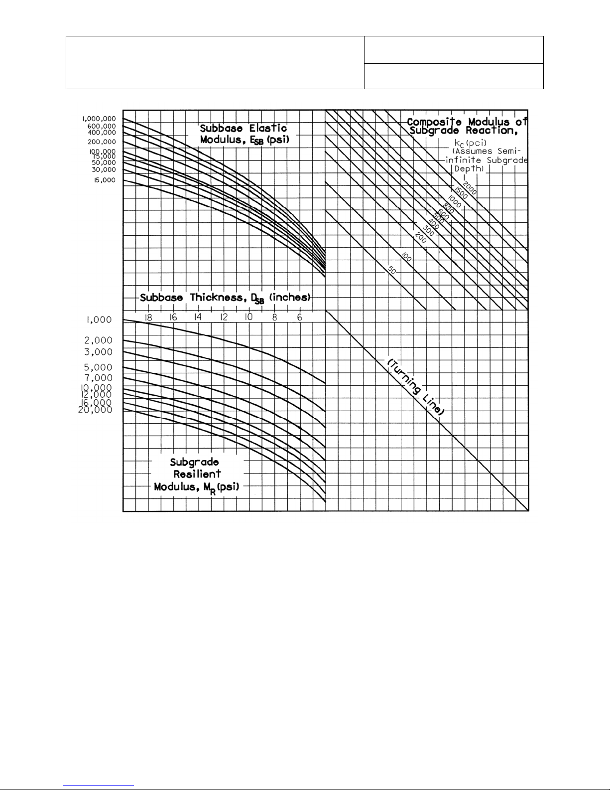
301.4 Composite Modulus of Subgrade Reaction
The composite modulus of subgrade reaction (kc) represents the combined effect of the subgrade
stiffness or subgrade modulus of resilience, as discussed in Section 203.1, and the stiffness, or elastic
modulus, and thickness of the subbase material. The pavement design process requires the designer to
choose the subbase prior to determination of the required slab thickness. The values for elastic modulus
of the subbase for ODOT materials are listed in Figure 301-1. Figure 301-2 is a nomograph that
determines the composite modulus of subgrade reaction.
A 6 inch (150 mm) granular base, item 304, is recommended as a subbase under all concrete
pavements to prevent pumping. The granular base is required for concrete pavement built over a
chemically stabilized subgrade. For very low traffic situations (less than 500,000 design ESALs) or on
non-stabilized granular subgrades, consideration may be given to eliminating the granular base.
301.5 Loss of Support
Loss of support (LS) is included in the design of rigid pavements to account for the potential loss
of support arising from subbase erosion or differential vertical soil movements. The potential of a material
to pump is an indication support may be lost. Loss of support is treated in the design procedure by
reducing the composite modulus of subgrade reaction. Figure 301-1 lists the LS factors to be used for
ODOT materials.
July 2014 300-2
Page 5

300 Rigid Pavement Design
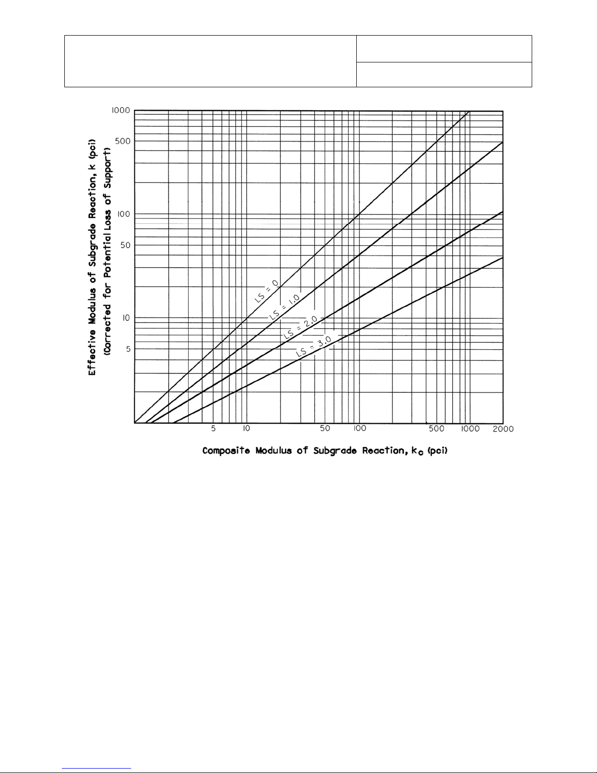
301.6 Effective Modulus of Subgrade Reaction
The effective modulus of subgrade reaction (k) is the composite modulus of subgrade reaction as
modified by the loss of support. Figure 301-3 is a nomograph that determines the effective modulus of
subgrade reaction.
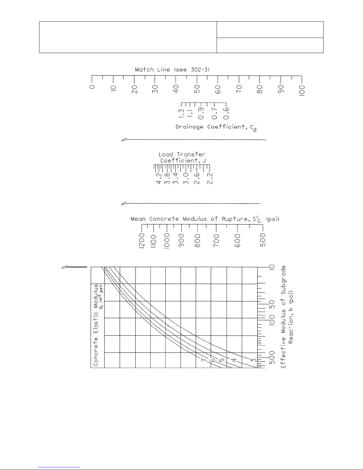
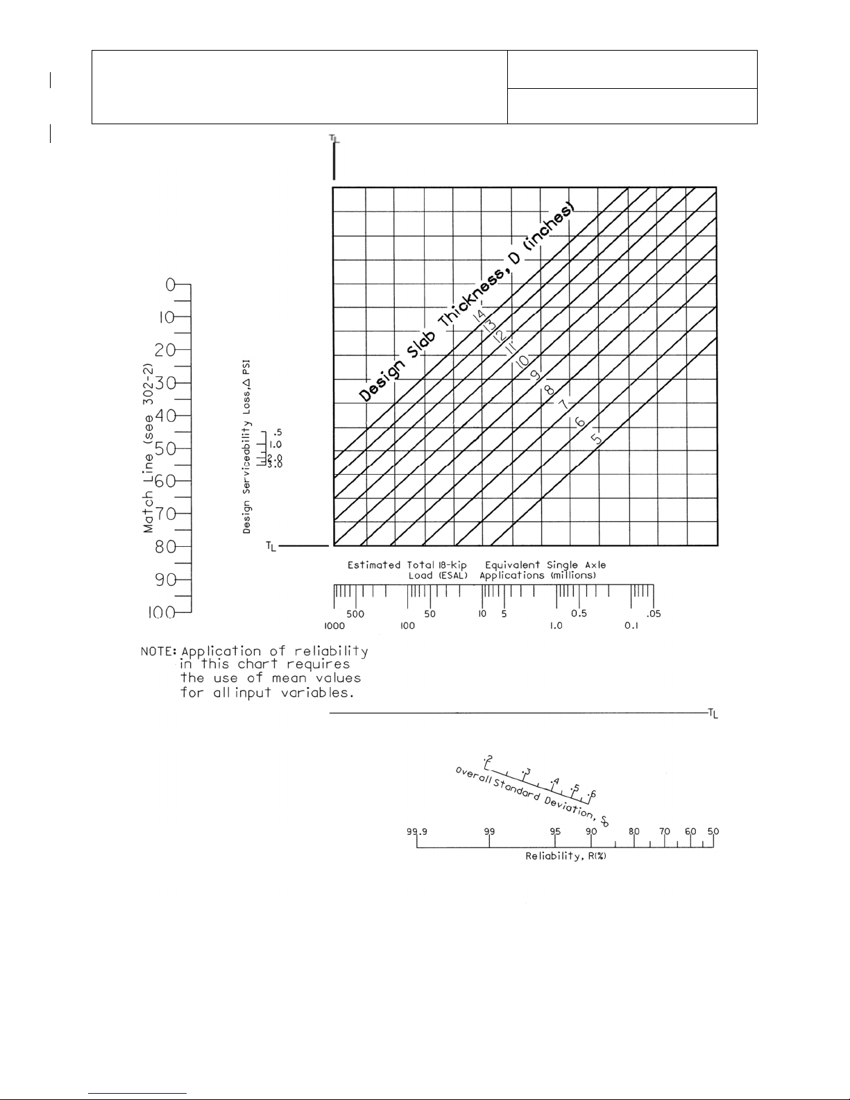
302 Thickness Determination
All of the design input information is required prior to determination of design thickness. Design
thickness is determined using the nomographs found in Figures 302-2 and 302-3. An example rigid
pavement design is provided in Figure 302-1. Concrete pavement thicknesses should be rounded to the
nearest 0.5 inch (10 mm) increment.
Adequate concrete cover is needed to transfer stresses between the concrete and the dowel
bars. Because of the required concrete cover, the minimum thickness of concrete pavement is 8 inches
(200 mm). In special situations where the standard specifications are modified to eliminate the dowels,
the minimum recommended thickness for concrete pavement is 6 inches (150 mm).
302.1 Ramps and Interchanges
If traffic and soils data is available, ramps, collector-distributor lanes, directional roadways, etc.,
may be designed individually. More common is to use the same thickness as the mainline or reduce the
mainline thickness by 1-inch (25 mm).
303 Jointing and Shoulder Considerations
303.1 Transverse Joints
Transverse joints are provided to control cracking. The closer the joint spacing, the less likely a
mid-panel crack will develop. Ohio uses 15-foot (4.6 m) joint spacing for non-reinforced concrete. For
reinforced concrete, 60-foot (18.3 m) joint spacing was used before about 1967 when it was reduced to
40 feet (12.2 m), then in the early 1980's it was further reduced to 27 feet (8.2 m) for several more years
and then to the current standard of 21 feet (6.5 m).
Load transfer is the critical element at joints. In undoweled pavements, load transfer is provided
by aggregate interlock. Aggregate interlock is lost when slabs contract and the joints open up. Interlock
is also slowly destroyed by the movement of the concrete as traffic passes over. Given the high
temperature variations and heavy truck traffic in Ohio, aggregate interlock alone is not effective and
faulting is the primary result. To provide load transfer at the joints, 18-inch (460 mm) long, smooth dowels
are used which allow for expansion and contraction. ODOT specifications require dowels in all transverse
joints in all mainline concrete pavements and bases. Transverse joint design and spacing requirements
are shown in the Standard Construction Drawings.
303.2 Expansion and Pressure Relief Joints
As slabs contract due to seasonal temperature changes, joints and cracks open allowing
incompressible materials into the pavement system. Subsequently, the pavement can grow in length and
create pressure. Pressure can lead to spalling, blowups, or damage to bridge back-walls. Having a small
amount of pressure in a pavement may be good since lack of pressure allows joints and cracks to open
which reduces load transfer. Slight pressure buildup in rigid pavement seldom creates pavement
distress. Nonetheless, when distresses are found, they tend to require some type of maintenance, and
may require immediate care in the case of a blowup.
July 2014 300-3
Page 6

300 Rigid Pavement Design
To control pressure buildup, expansion joints and pressure relief joints are used. The most
common need for an expansion joint or a pressure relief joint is to protect bridge back-walls. Four types
of pressure relief joints are detailed in the Standard Construction Drawings. For new pavement
construction, the Type A joint should be provided at all bridge approaches where the bridges are over 300
feet (90 m) apart. Where bridges are less than 300 feet (90 m) apart, the standard expansion joints as
required by C&MS Item 451 and detailed in the Standard Construction Drawings are considered
adequate. Use of pressure relief joints for pavements being rehabilitated is discussed in Section 500.
303.3 Longitudinal Joints
Longitudinal joints are required whenever the pavement width exceeds 18 feet (5.4 m) and are
recommended whenever the width exceeds 15 feet (4.5 m). Joints in mainline pavement are to be
located at the lane lines. W here project geometrics permit, 14-foot (4.3 m) wide slabs striped at 12 feet
(4.2 m) are recommended to provide additional edge support for the outside, truck lane.
All lanes, shoulders, and ramps for traffic moving in the same direction should be tied together
using a standard longitudinal joint as detailed in Standard Construction Drawing BP-2.1. Anytime traffic is
expected to cross a longitudinal joint (between lanes, from lane to shoulder, etc.) the joint should be tied.
Anytime traffic is not intended or expected to regularly cross a longitudinal joint (from shoulder to a barrier
foundation, from shoulder to a paved gore area, anytime two shoulders meet, etc.) the joint should not be
tied. Project specific details dictate exactly which joints need to be tied and which do not. The designer
should consider the needs of traffic when deciding what type of joint to use. There is no strict limit on the
maximum width that may be tied together. On undivided, bi-directional roadways, the centerline joint may
or may not need to be tied depending on the project specifics.
On 16-foot (4.9 m) wide ramps, a tied longitudinal joint down the middle is required as shown in
Standard Construction Drawing BP-6.1. This will guard against longitudinal cracking and may allow
future repair work to be performed on half the ramp while traffic is maintained on the other half and
shoulder.
At intersections, where two independent pavements meet, a longitudinal joint without tie bars is
required to separate the two pavements and allow for independent movement.
303.4 Intersection Jointing Details
Intersections require careful consideration of the joint layout, and dowel and tie bar placement. In
order to provide load transfer, control cracking, and prevent intersecting pavements from hindering the
movement of one another, jointing diagrams should be provided as part of the plans. Joint diagrams
should be designed with ease of construction in mind, as well as consideration of future rehabilitation and
maintenance of traffic needs. The number of longitudinal joints should be kept to a minimum, and all
slabs should be the same width, if possible. Examples of jointing diagrams are included in the Location &
Design Plan Preparation Sample Plan Sheets-Volume Three. In addition, there are various publications
provided by the American Concrete Pavement Association (ACPA) that provide guidance for intersection
joint layout.
303.5 Shoulder Considerations
Shoulders are used to provide an area for accommodation of disabled vehicles, for lateral support
of the base and surface courses, to improve the safety of a highway, and for maintenance of traffic
operations during maintenance and rehabilitation work.
Shoulders for concrete pavements should be constructed of concrete with the same thickness as
the driving lanes’ pavement whenever a paved shoulder is required. Having the same thickness allows
extensive use of the shoulder for maintenance of traffic with little, if any, risk of failure and reduces the
July 2014 300-4
Page 7

300 Rigid Pavement Design
complexity of construction. Tying concrete shoulders to the driving lanes provides lateral support and
spreads the load over a greater area.
Concrete shoulders should use non-reinforced concrete even if the driving lanes are reinforced.
The plans should include a note modifying the transverse joint spacing of the non-reinforced shoulders if
tied to reinforced driving lanes. In all cases, the shoulder joints should match the spacing and alignment
of the driving lanes to form one continuous joint across the pavement. Do not place any intermediate
joints in the shoulder.
Transverse joints in shoulders are not dowelled except within 500 feet (150 m) of a pressure relief
joint. Dowels may be added by plan note if the shoulders will be used to carry traffic during extended (9
months or more) maintenance of traffic operations. The amount of truck traffic using the shoulder should
be evaluated prior to requiring dowels.
Using other types of shoulders, such as flexible, surface treated, stabilized aggregate, or turf
shoulders should be in accordance with the Location & Design Manual, Volume One - Roadway Design.
Regardless of the type of shoulder used, the base and subgrade should be designed to drain water away
from the pavement, rather than towards it. Examples of typical sections depicting rigid pavement with
different types of unpaved shoulders are shown in Figure 303-1.
303.6 Edge Course Design
The aggregate base for a rigid pavement should extend 18 inches (450 mm) beyond the edge of
the travelled way, or to the outside edge of the porous backfill over the pipe underdrain, or to 6 inches
(150 mm) beyond the outside edge of the paved shoulder, whichever is greater.
Where curb and gutter or integral curb is used, subbase should extend 12 inches (300 mm)
beyond the back of the curb or to the outside edge of the porous backfill over the pipe underdrain,
whichever is greater. Refer to Location & Design Manual, Volume 2 - Drainage Design and Sample Plan
Sheets.
304 Concrete Pavement Usage Guidelines
304.1 Item 451 Reinforced Concrete Pavement
The use of item 451 is seldom if ever recommended. It is most commonly used when new
concrete is being tied to reinforced concrete constructed by a previous project. It is also used in
intersection work or near skewed bridges where long or odd shaped slabs may exist.
304.2 Item 452 Non-Reinforced Concrete Pavement
Item 452 is recommended for all large-scale concrete pavement projects. Item 452 is also
recommended for small projects as long as the proper joint spacing can be achieved. Projects that have
numerous irregular shaped slabs may be better suited to item 451.
304.3 Item 884 Warranty Concrete
The use of warranty concrete is allowed only with permission of the Division of Construction
Management. Requests to use warranty concrete should be directed to the warranty coordinator.
304.4 Item 305 Concrete Base
Item 305 is used anytime a composite pavement is being constructed. The most common use of
305 is widening next to an existing composite pavement.
July 2014 300-5
Page 8

300 Rigid Pavement Design
304.5 Class of Concrete
Class QC1 is recommended for all mainline, shoulder, and ramp concrete in excess of 250 feet
(75 m) of continuous pavement.
Class QC MS or QC FS may be used for smaller, repair-type areas. These mixes are intended
for joint and crack repairs or individual slab replacements. They are not intended for long stretches of
continuous pavement and are not expected to perform well if used in such applications.
The QC/QA designation is to be added if any single concrete pavement pay item exceeds 10,000
square yards (8500 square meters). The QC/QA designation may be added to all concrete pavement
items if any single item meets the threshold.
305 Warranty Concrete
The use of warranty concrete does not change the thickness design in any way. The same inputs
are used and the same thickness is determined regardless of whether warranty concrete will be used or
conventional Item 451 or 452 concrete. More information on concrete pavement warranties is available in
the Warranty Application Guidelines in the Innovative Contracting Manual published by the Office of
Construction Administration and in the Item 884 Portland Cement Concrete Pavement (7 Year Warranty)
specification.
306 Smoothness Specifications
Incentive/disincentive for smoothness is specified using Proposal Note 420 Surface Smoothness
Requirements for Pavements. PN 420 is recommended for all eligible projects. The Designer Note
details the eligibility requirements. Smoothness incentives generally result in better attention to detail by
the contractor and higher quality pavement overall. Smooth, high quality pavements are expected to
perform better for a longer time, potentially resulting in cost savings to the Department.
The designer should ensure the contractor has a reasonable opportunity to achieve the incentive.
Projects that may otherwise be eligible but have numerous manholes, drainage structures, business or
residential driveways, etc., are usually not good candidates for smoothness incentive.
307 Composite Pavement
Composite pavement herein refers to a rigid base with an asphalt surface. Composite pavements
are rarely designed and built on ODOT projects. When they are used it is often at the request of a local
government agency. Where local preference is strong and there has been good performance,
consideration may be given to the design and specification of a composite pavement.
307.1 Composite Pavement Design
Composite pavements are designed as rigid pavements. Once the required thickness is
determined, the concrete thickness is reduced by one inch (25 mm) and replaced with 3 or 3.25 inches
(75 mm - 83 mm) of asphalt. This ratio of 1 inch (25 mm) of concrete to 3 inches (75 mm) of asphalt
holds true only for the first inch (25 mm) of concrete removed and is an approximation at best.
The minimum asphalt overlay thickness on a rigid pavement or base is 3 inches (76 mm). Lift
thickness requirements for specific asphalt materials may require a 3.25 inch (83 mm) minimum overlay
thickness. The minimum concrete thickness of 8 inches (200 mm) still applies.
July 2014 300-6
Page 9

300 Rigid Pavement Design
307.2 Composite Pavement Typical Section Design
Composite pavement should be constructed using Item 305 Concrete Base. The width of the
concrete base should be extended beyond the wearing surface by 3 inches (75 mm). Item 409 Sawing
and Sealing Asphalt Concrete Pavement Joints is recommended for most newly constructed composite
pavements.
307.3 Composite Pavement Warranty
There is not a seven year warranty specification for composite pavements. The only warranty
that could be used on a composite pavement is a three year warranty, Supplement 1059, on the asphalt
concrete surface course. The use of Supplement 1059 is allowed only with permission of the Division of
Construction Management. Requests to it should be directed to the warranty coordinator.
307.4 Composite Pavement Smoothness Specifications
Proposal Note 420 Surface Smoothness Requirements for Pavements may be used with
composite pavements for smoothness incentive/disincentive. The guidelines in Section 306 apply.
July 2014 300-7
Page 10

300 Rigid Pavement Design
List of Figures
Figure Date Subject
301-1 July 2016 Rigid Pavement Design Parameters
301-2 July 2008 Composite Modulus of Subgrade Reaction (kc)
301-3 July 2008 Effective Modulus of Subgrade Reaction (k)
302-1 July 2016 Rigid Pavement Design Example
302-2 July 2008 Rigid Pavement Design Chart Segment 1
302-3 July 2016 Rigid Pavement Design Chart Segment 2
303-1 July 2008 Surface Treated Shoulder and Stabilized Aggregate Shoulder
Typical Sections
Page 11

301-1
Reference Section
Rigid Pavement Design Parameters
MATERIAL PROPERTIES
Modulus of Rupture (S’c) 700 psi
Modulus of Elasticity (Ec) 5,000,000 psi
Load Transfer Coefficient (J) - Doweled, Edge Support* 2.7
Load Transfer Coefficient (J) - Doweled, No Edge Support* 3.2
* Edge support includes tied concrete shoulders, integral curb, widened lane, etc. Widened lane refers to
concrete slabs built 14 feet (4.2 m) wide or wider, but striped for a standard 12-foot (3.6 m) lane, leaving 2
feet (0.6 m) outside the traveled lane to provide edge support.
SUBBASE FACTORS
July 2016
301
Recommended
ODOT Specification
Item 301, 302 Asphalt Concrete Base 4 300,000 0
Item 304 Aggregate Base** 6 30,000 1
Natural Subgrade*** 2
** When the entire subgrade is chemically stabilized (global chemical stabilization), the elastic modulus of
the Item 304 Aggregate Base is increased to 36,000 psi.
*** Not recommended for most applications. See Section 301.4
Thickness (in.)
(DSB)
Elastic Modulus
(psi)
(ESB)
Loss of Support
(LS)
Page 12
Composite Modulus of Subgrade
Ref
erence
Section & Figure
Reaction (kc)
301-2
July 2008
301.4, 302-1 (step 3)
Page 13
Effective Modulus of Subgrade
Ref
erence
Section & Figure
Reaction (k)
301-3
July 2008
301.6, 302-1 (step 4)
Page 14

302-1
Reference Section
Rigid Pavement Design Example
Page 1
Given:
• Pavement of choice: Doweled, jointed concrete
• Subbase: 6 inches Item 304 Aggregate Base
• Shoulders: Tied, jointed, concrete
• Number of Lanes: 4 (2 per direction)
• Functional Classification: Principal Arterial (Rural)
• 2018 Traffic: 15,800 ADT
• 2038 Traffic: 22,450 ADT
• 24 hour truck %: 18%
• Design Period: 20 years
• Open to Traffic: 2019
• Subgrade CBR: 5 (from GB1 analysis)
Problem: Solve for the thickness of the concrete slab.
Solution:
Step 1 - Determine the 18-kip equivalent single axle loading (ESAL).
Since the project is expected to open to traffic in 2019, the ESAL projection should be for 2019 to 2039.
Calculate the mid-year (2029) ADT, rounded to nearest ten:
2029 ADT = 15,800+(22,450-15,800)(11/20)
2029 ADT = 19,460
The equations in Section 202.2 are used with
Directional distribution, D = 50% (Figure 202-1)
Lane factor = 95% (Figure 202-1)
B:C ratio = 5:1 (Figure 202-1)
ESAL conversion factor for B trucks = 1.67 (Figure 202-1)
ESAL conversion factor for C trucks = 0.44 (Figure 202-1)
Using the equations given in Section 202.2:
ESAL's from B trucks = 19,460(0.18)(0.50)(0.95)(5/6)(1.67) = 2,315
ESAL's from C trucks = 19,460(0.18)(0.50)(0.95)(1/6)(0.44) = 122
Total daily ESAL's = 2,315+122 = 2,437 ESAL/day
Design period ESAL's = 2,437 ESAL/day * 365.25 days/yr. * 20 years = 17,802,285
use 17.8x10⁶ ESAL’s
July 2016
302
Page 15

302-1
Reference Section
Rigid Pavement Design Example
Page 2
Step 2 - Determine the subgrade resilient modulus (Mr) using the formula given in Section 203.1.
Mr = 1200 * CBR
Mr = 1200 * 5
Mr = 6000 psi
Step 3 - Determine the composite modulus of subgrade reaction (kc) using Figure 301-2.
Starting with the given subbase thickness (DSB) of 6", a line is projected up to the subbase elastic
modulus (ESB) curve of 30,000 psi (Item 304 Aggregate Base from Figure 301-1). From this point on the
30,000 psi curve, a line is projected to the right for future intersection. Similarly, from the 6" subbase
thickness (DSB), a line is projected down to the subgrade resilient modulus (Mr) curve of 6000 psi. From
this point on the 6000 psi curve, a line is projected to the right to the turning line and then projected up to
intersect with previously projected line. This intersection results in a composite modulus of subgrade
reaction (kc) of 335 pci.
Step 4 - Determine the effective modulus of subgrade reaction (k) using Figure 301-3.
Using the composite modulus of subgrade reaction (kc) determined in Step 3, enter the chart on the
bottom. Project a line from 335 pci up to LS = 1.0 (from Figure 301-1 for Item 304 Aggregate Base).
Then project a line straight across to the vertical axis. This results in an effective modulus of subgrade
reaction (k) of 110 pci.
Step 5 - Determine the thickness of the concrete slab using Figures 302-2 and 302-3.
Figure 302-2 is used to solve for the match line number using the following information:
Effective modulus of subgrade (k) = 110 pci (Step 4)
Concrete elastic modulus (Ec) = 5,000,000 psi (Figure 301-1)
Concrete modulus of rupture (S’c) = 700 psi (Figure 301-1)
Load Transfer Coefficient (J) = 2.7 (Figure 301-1)
Drainage coefficient (Cd) = 1.0 (Section 205.2)
The resulting match line number is then used on Figure 302-3, along with the following information, to
solve for the design slab thickness (D).
Design serviceability loss (PSI) = 1.7 (Figure 201-1)
Reliability = 85% (Figure 201-1)
Overall standard deviation = 0.39 (Figure 201-1)
18-kip equivalent single axle load = 17.8x10⁶ ESAL (Step 1)
Therefore: design slab thickness (D) = 10 inches
July 2016
302
Page 16
Rigid Pavement Design Chart
Ref
erence
Section & Figure
Segment 1
302-2
July 2008
302, 302-1 (step 5)
Page 17
Rigid Pavement Design Chart
Ref
erence
Section & Figure
Segment 2
302-3
July 2016
302, 302-1 (step 5)
Page 18
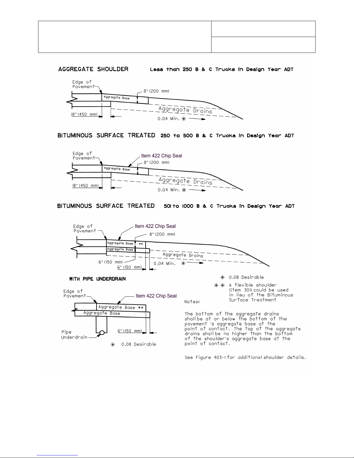
Surface Treated Shoulder and
Stabilized Aggregate Shoulder
Typical Sections
303-1
July 2008
Reference Section
205.1, 303.5, 303.6
 Loading...