

Page 1

ViewPoint 8050 Videoconferencing Terminal
User Guide
HUAWEI TECHNOLOGIES CO., LTD.
Page 2

Page 3

ViewPoint 8050 Videoconferencing Terminal
V200R001
User Guide
Issue 02
Date 2007-12-01
Huawei Technologies Proprietary
Page 4

Huawei Technologies Co., Ltd. provides customers with comprehensive technical support and service. Please
feel free to contact our local office or company headquarters.
Huawei Technologies Co., Ltd.
Address: Administration Building, Huawei Technologies Co., Ltd.,
Website: http://www.huawei.com
Bantian, Longgang District, Shenzhen, 518129, People’s Republic of China
Copyright © Huawei Technologies Co., Ltd. 2007. All rights reserved.
No part of this document may be reproduced or transmitted in any form or by any means without prior written consent of Huawei
Technologies Co., Ltd.
Trademarks and Permissions
and other Huawei trademarks are trademarks of Huawei Technologies Co., Ltd.
All other trademarks and trade names mentioned in this document are the property of their respective holders.
Notice
The information in this document is subject to change without notice. Every effort has been made in the preparation of this
document to ensure accuracy of the contents, but all statements, information, and recommendations in this document do not
constitute the warranty of any kind, express or implied.
Huawei Technologies Proprietary
2
Page 5
Electronic products can cause a fire or bodily injury if the safety precautions are not followed.
This User Guide provides important caution notices to prevent accidents and ensure safe handling of the product. Read it
carefully to understand how to use the product safely. After reading, retain it for future reference.
Safety Precautions
HUAWEI products are designed with careful consideration for safety. However, if used improperly, electronic products can cause serious
injury and even death as a result of fire or electric shock, so they should be considered dangerous.
Observe the following precautions to avoid accidents.
Routine Inspection
For a long and safe product life, we recommend routine inspections.
Contact your place of purchase or HUAWEI Customer Service for the details and
cost of inspections.
If Damaged, Do Not Use
Immediately contact your place of purchase or HUAWEI Customer Service.
If an Abnormality Occurs
• If smoke appears
• If an unusual sound or smell occurs
• If water or a foreign object gets inside
• If the product is dropped or the case is damaged
m
a Turn the power off.
b Unplug the power cord or supply cable.
c Immediately contact your place of purchase or HUAWEI Customer Service.
Meanings of Warning
Symbols
The following symbols are used in
the guide and on the product.
Familiarize yourself with the
symbols before reading the rest of
the guide.
Failure to follow the precautions
indicated with this symbol can
result in serious injury or death due
to fire or electric shock.
Failure to follow the precautions
indicated with this symbol can
result in bodily injury due to electric
shock or other accident, and damage
may occur to surrounding objects.
Hazard Symbols
Hazard-Avoidance
Symbols
Required-Action Symbols
3
Page 6

Owner’s Record
The model and the serial numbers are located at the rear.
Record the serial number in the space provided below.
Refer to these numbers whenever you call upon your
HUAWEI dealer regarding this product.
Model No. ViewPoint 8050 Serial No.
WARNING
Use the AC power adapter provided with this equipment as
a power supply source.
Manufacture Type No.
NaganoJRC SQ2N120W19P-01
This equipment generates, uses, and can radiate radio
frequency energy and, if not installed and used in
accordance with the instruction manual, may cause
harmful interference to radio communications. Operation
of this equipment in a residential area is likely to cause
harmful interference in which case the user will be
required to correct the interference at his own expense.
You are cautioned that any changes or modifications not
expressly approved in this manual could void your
authority to operate this equipment.
All interface cables used to connect peripherals must be
shielded in order to comply with the limits for a computing
device pursuant to Subpart B of Part 15 of FCC Rules.
Any other power sources may result in hazards such as a
fire.
Disconnect device of this equipment is the mains plug of
the AC adapter.
The mains plug on this equipment must be used to
disconnect mains power.
Please ensure that the socket outlet is installed near the
equipment and shall be easily accessible.
In the event of abnormal operations, disconnect the mains
plug.
NOTICE
Use the power cord set approved by the appropriate testing
organization for the specific countries where this unit is to
be used.
CAUTION for LAN port
For safety reason, do not connect the LAN port to any
network devices that might have excessive voltage.
For the customers in the USA
WARNING
This device complies with Part 15 of the FCC Rules.
Operation is subject to the following two conditions: (1)
This device may not cause harmful interference, and (2)
this device must accept any interference received,
including interference that may cause undesired
operation.
This equipment has been tested and found to comply with
the limits for a Class A digital device, pursuant to Part 15
of the FCC Rules. These limits are designed to provide
reasonable protection against harmful interference when
the equipment is operated in a commercial environment.
Disposal of the used lamp
For the customers in the USA
Lamp in this product contains mercury. Disposal of these
materials may be regulated due to environmental
considerations. For disposal or recycling information,
please contact your local authorities or the Electronic
Industries Alliance (www.eiae.org).
For the customers in Canada
This Class A digital apparatus complies with Canadian
ICES-003.
Cet appareil numérique de la classe A est conforme à la
norme NMB-003 du Canada.
For the customers in Europe
The manufacturer of this product is Huawei Technologies
Co., Ltd., Administration Building, Huawei Technologies
Co., Ltd., Bantian, Longgang District, Shenzhen, 518129,
People’s Republic of China.
The Authorized Representative for EMC and product
safety is Huawei Technologies Co., Ltd., Administration
Building, Huawei Technologies Co., Ltd., Bantian,
Longgang District, Shenzhen, 518129, People’s Republic
of China. For any service or guarantee matters please refer
to the addresses given in separate service or guarantee
documents.
For the customers in Europe, Australia and New
Zealand
Warning
This is a Class A product. In a domestic environment, this
product may cause radio interference in which case the
user may be required to take adequate measures.
In the case that interference should occur, consult your
nearest authorized HUAWEI service facility.
This apparatus shall not be used in the residential area.
4
Page 7

Table of Contents
WARNING ...................................................................................10
CAUTION ....................................................................................11
Precautions ....................................................................................13
Chapter 1 Installation and Preparation
Using This Guide ...........................................................................14
Features..........................................................................................15
System Components .....................................................................16
Basic System Components .................................................................. 16
Optional Equipment ............................................................................ 16
Names and Functions of Parts .....................................................17
ViewPoint 8050 Videoconferencing Terminal.................................... 17
Indicator Names and Functions ........................................................... 18
ViewPoint 8050-DSB Dual Stream Box (Optional) ........................... 19
System Connections .....................................................................20
About the Connectors.......................................................................... 20
Connection Precautions....................................................................... 20
System Connection via a LAN............................................................ 20
Adjusting the Height of the Display .............................................21
Turning the System On/Off...........................................................22
Opening the Lens Cover...................................................................... 22
Turning the System On........................................................................ 22
Turning the System Off....................................................................... 23
Setting the Videoconferencing Terminal to Standby Mode................ 23
Adjusting the Volume ......................................................................... 23
Adjusting the Picture Quality .............................................................. 23
Displaying Help................................................................................... 23
Displaying Version and Option Information....................................... 23
Setting Up the System for the First Time — Initial Setup
Wizard ......................................................................................24
Using the Menu ..............................................................................25
Menu Configurations........................................................................... 25
Explanation of Menus ......................................................................... 26
Entering Characters ............................................................................. 28
Table of Contents
5
Page 8

Chapter 2
Registration and Setup
Registering Local Information......................................................29
Opening the Setup Menu..................................................................... 29
Answer Setup Menu ............................................................................ 30
Device Setup Menu ............................................................................. 30
Audio Setup Menu............................................................................... 31
Network Setup Menu........................................................................... 32
Communication Mode Menu............................................................... 33
Administrator Setup Menu .................................................................. 35
Display Setup Menu ............................................................................ 39
Registering a Remote Party in the Phone Book .........................41
Registering a New Remote Party ........................................................ 41
Changing the Contents of the Phone Book ......................................... 42
Deleting a Registered Remote Party ................................................... 42
Copying an Entry in the Phone Book.................................................. 43
Creating a Private Phone Book ........................................................... 43
Using the Shared Phone Book............................................................. 44
Checking the History of Outgoing and Incoming Calls ...................... 45
Registering a Remote Party for One Touch Dial.........................46
One Touch Dial Registration............................................................... 46
Registering the Private One Touch Dial.............................................. 46
Setting Up the Network Configurations.......................................47
LAN (Connecting via DHCP) ............................................................. 47
LAN (Connecting Through a Router) ................................................. 47
LAN (Connecting Through a Gatekeeper) .......................................... 48
LAN (Connecting Through NAT)....................................................... 48
LAN (Connecting With H.460 Firewall Traversal) ............................ 49
LAN (PPPoE Connections) ................................................................. 50
Chapter 3 Basic Videoconference
Starting a Conference by Calling a Remote Party ......................52
Turning on the Power .......................................................................... 52
Using the Launcher Menu ................................................................... 53
Using the Communication Screen....................................................... 54
Status & Info Menu ............................................................................. 55
Calling a Remote Party Using One Touch Dial .................................. 56
Calling a Remote Party by Entering the IP Address in the Launcher
Menu .......................................................................................... 57
Calling a Remote Party Registered in the Phone Book....................... 57
Calling a Remote Party From the Incoming/Outgoing Call History... 58
6
Table of Contents
Page 9

Receiving a Call From a Remote Party ........................................59
Answering a Call From a Remote Party.............................................. 59
Ending the Conference ........................................................................ 59
Joining a Multipoint Videoconference.........................................60
Adjusting the Picture and Sound .................................................61
Adjusting the Picture Quality .............................................................. 61
Adjusting the Volume ......................................................................... 61
Cutting Off the Sound Momentarily - Mic Off Function.................... 61
Cutting Off the Sound On Answering - Mic Off Function ................. 61
Synchronizing Audio and Video - Lip Sync Function ........................ 61
Reducing Echo - Echo Canceller......................................................... 61
Adjusting the Camera....................................................................62
Adjusting the Zoom and Camera Angle.............................................. 62
Accepting Remote Camera Control .................................................... 63
Adjusting the Brightness ..................................................................... 63
Presetting the Zoom and Angle Settings ............................................. 64
Recalling a Preset Zoom and Angle Setting........................................ 64
Changing the Screen Layout ........................................................65
Bringing up the Screen Layout Setup Menu ....................................... 65
Switching the Display ......................................................................... 65
Chapter 4 Videoconference With Optional Equipment
Using Still Images Stored in a “Memory Stick” for a
Videoconference .....................................................................67
Displaying a Still Image Stored on a “Memory Stick” ....................... 67
Sending a Still Image Stored on a “Memory Stick”............................ 68
About “Memory Stick” ..................................................................69
Formatting a “Memory Stick”............................................................. 70
Sending Motion Pictures as Still Images.....................................70
Sending Still Images Using the Still Image Menu .............................. 70
Receiving Still Images......................................................................... 71
Receiving Whiteboard Images ............................................................ 71
Saving Still Images........................................................................72
Saving Remote Party Pictures Automatically – Automatic Image
Capture Feature.......................................................................... 72
Saving Still Images Using the Still Image Menu ................................ 72
Using External Microphone and Headphones ............................73
Controlling the Remote System With Tone Signals - DTMF
Transmission ................................................................................73
Accessing the Videoconferencing Terminal ...............................74
Using the Web Monitor Function........................................................ 74
Using a Web Browser.......................................................................... 74
Using Telnet ........................................................................................ 74
Table of Contents
7
Page 10

Chapter 5 Data Conference Using Dual Stream Box
Installing the Dual Stream Box.....................................................76
Connection Example Using the Dual Stream Box......................77
Using Video From Connected Equipment for a Conference ..... 78
Operating the System During a Conference........................................ 78
Chapter 6
Use as Computer Display
Using as Computer Display ..........................................................80
Connecting to a Computer................................................................... 80
Separate Mouse ................................................................................... 81
Shared Mouse ...................................................................................... 81
Displaying the Picture From the Computer......................................... 82
Displaying the Picture From the Computer During a
Videoconference ........................................................................ 82
Switching Between Videoconference Display and Computer
Display .....................................................................................83
Calling a Remote Party or Receiving a Call at the PC Screen...84
Calling a Remote Party While PC Screen Is Shown ........................... 84
Receiving a Call While PC Screen Is Shown...................................... 84
Adjusting the Picture Quality on the Display..............................84
Display Setup Menu for Videoconference .......................................... 84
Display Setup Menu for the Computer Picture ................................... 85
Differences in Wide Mode Settings .................................................... 86
Chapter 7 Web Control Function
Open the Web Page .......................................................................87
Identify a User ................................................................................88
How To Use the “Web Control” Window .....................................88
Select a Tool...................................................................................89
How To Use “Controller” ..............................................................90
How To Use “Dial/Disconnect”.....................................................91
How To Use “Phone Book”...........................................................92
“Phone Book-Edit” Page ..................................................................... 93
“Phone Book-New” Page .................................................................... 94
How To Use “Setup”......................................................................95
How To Configure KIOSK Mode ....................................................... 96
To Display the “Send Message” Page................................................. 97
To Reset the System ............................................................................ 98
How To Use “Status & Info” .........................................................99
To Display the Cause Code List........................................................ 100
To Display the Call Log .................................................................... 100
How To Use “Monitor” ................................................................101
8
Table of Contents
Page 11

Appendix
Screen Indicators.........................................................................102
On Screen Messages...................................................................103
Troubleshooting ..........................................................................107
Specifications ..............................................................................108
Acceptable RGB Input/Output Signals ............................................. 111
Pin Assignment.................................................................................. 112
Pin Assignment on Optional Board Connectors................................ 113
List of Port Numbers Used on the ViewPoint 8050.......................... 113
Videoconferencing Room Layout ..............................................114
Glossary .......................................................................................115
Menu Configuration.....................................................................117
Table of Contents
9
Page 12
WARNING
Failure to follow precautions
may result in death or serious
injury from fire or electric shock.
Avoid damaging the AC power
cord or DC supply cable
If the AC cord or DC supply cable is
damaged, fire or electric shock could
occur.
• Do not attempt to modify or repair
damaged cables.
• Do not pull on cables or place heavy
objects on them.
• Do not locate cables near heaters or
other hot devices.
• Always grasp the plug to unplug a cord
or cable.
If a cord is damaged, ask HUAWEI
Customer Service for a replacement.
Do not place the product
where it could be exposed to
rain, oily smoke, vapor or dust
Fire or electric shock could result.
Do not touch the power plug
during thunderstorms
You could receive an electric shock.
Do not connect with many
other devices
Connecting many devices to the same
power outlet can cause a fire if the current
exceeds the rated limit.
Ensure that the AC and DC
plugs of the AC adapter are
inserted securely
A plug that is not inserted securely can
cause a fire or electric shock.
Do not connect to a telephone
circuit or to a network other
than that specified
Connecting one of the following networks
or circuits to the network connector on the
product may cause excessive current flow
through the connector, which could result
in damage, overheating and fire.
Be especially careful to avoid connecting
to a home or business telephone circuit.
• Any network type other than 10BASET or 100BASE-TX
• A standard telephone circuit
• The digital jack of an ISDN (digital)
public telephone
• A PBX (digital switching circuit for
home or business telephones)
• Any home or business telephone circuit
• Any other telephone circuit besides the
above
Also, before connecting to a network, you
should consult with that network's
administrator.
10
Do not use the product when
there is possibility of a
lightning strike
A lightning strike may damage the
product or cause an electric shock. When
a thunderstorm is pending, disconnect
network cables and unplug the power to
avoid fire, electric shock or damage to the
product. Do not touch the product while a
thunderstorm is actually occurring.
WARNING
Page 13
CAUTION
Failure to follow these
precautions may result in injury
or damage to surrounding
objects.
Do not place the product on
an unstable surface
If placed on an unstable or slanted
surface, the product may fall and cause
injury. Verify that a surface is stable
before placing the product on it.
Do not block ventilation
openings
If a ventilation opening is covered,
overheating may cause smoke or ignite
a fire that could result in burns.
Turn power off when making
connections
Connecting the power cord or cables
while power is turned on may cause
electric shock or damage.
Use only the supplied AC
adapter and power cord
Using an AC adapter or power cord
other than that supplied may cause
electric shock or damage.
The AC adapter should only
be used for the specified
product
Using the AC adapter with another
product may damage the adapter or
that product.
Do not touch the power plug
with wet hands
Plugging or unplugging the power plug
with wet hands may cause an electric
shock.
Do not touch the AC adapter
with wet hands
You could receive an electric shock.
Do not attempt to
disassemble or modify
Fire, electric shock or injury could
result. Contact your place of purchase
or HUAWEI Customer Service for an
internal inspection or repair.
Turn the product off and
unplug it before cleaning
Cleaning the product while the power
is connected may cause an electric
shock.
Unplug the power cord and
disconnect the cables
before moving
Moving the product while the cord or
cables are connected could damage
them and cause a fire or electric shock.
Do not place the product
where it could be exposed
to direct sunlight, or near a
heater
In addition to deformation or damage
to the cabinet, fire could result from
lensing phenomena. Be especially
careful when installing near a window.
Do not allow water or
foreign objects to get inside
the product
Water or foreign objects inside the
product can cause fire or electric
shock.
If water or a foreign object is inside,
immediately turn the power off and
unplug the power cord or supply cable,
and contact your place of purchase or
HUAWEI Customer Service.
CAUTION
11
Page 14
Do not touch the product or
AC adapter when they have
been on for a long time
They can become quite hot during
normal usage.
Long-term exposure could result in
minor burns, redness or blistering.
Avoid long-term exposure of
the skin to ventilation
exhaust
Under some operating conditions,
warm air is exhausted from the
product.
Long-term exposure to this warm air
could result in minor burns, redness or
blistering.
When the product will not be
used for a long time, unplug
the power cord and AC
adapter
When the product is not used for a long
time, unplugging the AC adapter from
the output ensures safety.
Avoid watching the display
continuously for a long time
Watching a display screen
continuously for a long time can cause
eye fatigue and weakened eyesight.
If you begin to feel uncomfortable or
feel a pain in some part of your body
while watching the display,
immediately discontinue using the
system, and rest.
If the discomfort or pain persists after
resting, see a doctor.
Do not strike the LCD
The LCD is made of glass.
Do not place heavy objects on it, or
drop or forcefully strike the screen.
Subjecting the LCD to a strong shock
may cause damage or injury.
Connect and arrange the
cables properly
The product may drop or fall over if
you trip over the power cord or signal
cables, which could result in an injury.
Connect and install the cables with
sufficient care to avoid places where
people might step on or trip over them.
Take preventative action to
avoid falling or slipping
When installing or removing the
product from a rack, you could be
injured unless you take preventative
care to avoid falling or slipping. When
performing these activities, focus your
attention and take a stable posture. In
addition, check installation conditions
carefully, and ensure that the rack has
sufficient strength.
12
Do not step or place heavy
objects on the product
Doing so may cause injury from falling
or breakage.
CAUTION
Page 15

Precautions
The white flecks especially tend to be seen in the
following cases:
• when operating at a high environmental temperature
• when you have raised the gain (sensitivity)
Operating or storage location
Avoid operating or storing the system in the following
locations:
• Extremely hot or cold places
• Humid or dusty places
• Places exposed to strong vibration
• Close to sources of strong magnetism
• Close to sources of powerful electromagnetic radiation,
such as radios or TV transmitters
• Noisy places
LCD screen
Notes on use
• Do not expose the LCD screen surface to the sun. Doing
so may damage the screen surface.
• Do not push or scratch the LCD screen, or place objects
on top of the system. The image may become uneven or
the LCD panel may be damaged.
• If the system is used in a cold place, a smear may occur
in the picture or the picture may become dark. This does
not indicate a failure. These phenomena improve as the
temperature rises.
• Ghosting may occur when still pictures are displayed
continuously. It may disappear after a few moments.
• The screen and cabinet get warm when the system is in
use. This is not a malfunction.
Display pixels
Although the LCD display panel is made with highprecision technology and has an effective picture element
ratio of over 99.99%, black dots (dead pixels) may appear
on the screen or pixels may become permanently lit (red,
blue, green, etc.) or unlit. The appearance of dead pixels
after extended periods of use is common among LCD
display panels. Be aware that such appearances do not
represent a malfunction.
Aliasing
When fine patterns, stripes, or lines are shot, they may
appear jagged or flicker.
Note on laser beams
Laser beams may damage a CMOS sensor. You are
cautioned that the surface of a CMOS sensor should not
be exposed to laser beam radiation in an environment
where a laser beam device is used.
Built-in speakers
The speakers generate magnetism. To avoid damaging
the data, keep magnetic tapes and disks away from the
speakers.
Cleaning
• Before cleaning, disconnect the power cord from the
AC outlet.
• The LCD screen surface is finished with a special
coating. To remove dust from the screen surface, wipe
gently with a soft, dry cloth.
• Do not use volatile solvents such as alcohol, benzene or
thinners as they may damage the surface finishes.
• When you use chemical cleaning cloth, observe the
instructions that come with it.
• Do not apply volatile solvents such as an insecticide to
the screen, or allow rubber or plastic objects to touch to
the screen for a long time, as they may damage the
surface finishes.
Phenomena specific to CMOS sensors
The following phenomena that may appear in images are
specific to CMOS (Complementary Metal Oxide
Semiconductor) sensors. They do not indicate
malfunctions.
White flecks
Although the CMOS sensors are produced with highprecision technologies, fine white flecks may be
generated on the screen in rare cases, caused by cosmic
rays, etc.
This is related to the principle of CMOS sensors and is not
a malfunction.
Precautions
13
Page 16
Installation and
Chapter 1 Installation and Preparation
Preparation
Using This Guide
The chapters cover the following contents; please read the
chapters that may be required for your type of
videoconference.
Chapter 1: Installation and Preparation
This chapter guides you through the system configuration
and information required to use your Videoconferencing
Terminal for the first time. It shows you how to install and
connect your Videoconferencing Terminal, to turn the
system on/off and how to access basic on-screen menus.
Chapter 2:
This chapter describes how to register and set up all the
necessary items for system administrators, using the onscreen menus.
Registration and Setup
Chapter
Appendix
This chapter contains message and troubleshooting lists,
specifications, and glossaries.
1
Chapter 3: Basic Videoconference
This chapter guides you through the basic operations and
settings to conduct a videoconference. You will learn how
to conduct a conference from start to finish. It is
recommended that this chapter be read by participants in
the videoconference.
Chapter 4: Videoconference With Optional
Equipment
This chapter shows advanced videoconferencing using the
optional equipment.
Chapter 5: Data Conference Using Dual Stream
Box
This chapter shows you how to integrate data from a
computer or other external equipment into a
videoconference by using the optional Dual Stream Box.
Chapter 6:
This chapter shows you how to use the Videoconferencing
Terminal as a computer display.
Chapter 7: Web Control Function
This chapter shows you how to control and set up the
ViewPoint 8050 through the Web.
Use as Computer Display
14
Using This Guide
Page 17

Features
The ViewPoint 8050 Videoconferencing Terminal is a
videoconferencing system that allows natural, face-to-face
communications with a remote party by transmitting and
receiving images and sound via a LAN (Local Area
Network).
Integrated portable Videoconferencing
Terminal
All necessary elements of the system such as 17-type
wide-format display, camera equipped with digital pan/tilt
and zoom, codec, microphones and speakers are integrated
in a single compact cabinet for easy portability. The
integrated design plus VESA mount capability makes it
possible to set up a videoconference almost anywhere.
Up to 30 One Touch Dial entries
Remote parties to which you frequently connect can be
registered in the launcher menu. You can then establish a
connection simply by clicking a Dial button.
Supports worldwide standards
Full compliance with the ITU-T Recommendations
defined by the WTSC (World Telecommunications
Standardization Committee) assures easy connection with
remote parties in any country.
QoS (Quality of Service) function for
optimization of bandwidth and traffic
packet through network
“Packet Resend Request” and “Adaptive Rate Control”
functions incorporated, allowing solution for busy network
traffic or packet loss, which provides consistent highquality communication.
Easy setup and operation
The Help menu appears on the display for guidance of
operation. The menus used for the system administrator or
those for conference participants are separately displayed.
Memory Stick slot equipped
The Videoconferencing Terminal is equipped with a
Memory Stick slot, allowing the use of still images
recorded with a digital still camera and stored in the
“Memory Stick”.
You can create your own phone book and One Touch Dial
icons in a “Memory Stick” as your private phone book.
The ViewPoint 8050 features “Memory Stick PRO”.
Use as computer display
The display of the Videoconferencing Terminal can also
be used as a computer display.
If you receive a call from a remote party, the picture of the
remote party can be automatically displayed even while you
are using the system as a computer display.
Chapter 1 Installation and Preparation
Supports data conferences
Use of the optional ViewPoint 8050-DSB Dual Stream
Box allows the data from a computer to be incorporated in
the presentation or to be shown using a projector.
High transmission speeds and highquality picture
The Videoconferencing Terminal can handle LAN
bandwidths of up to 2048 kbps.
Support for a wide range of video/audio
compression formats
The Videoconferencing Terminal supports H.264,
MPEG4, H.263+, H.263, and H.261 for video
compression, and MPEG4 Audio, G.722, G.729, G.728,
and G.711 for audio compression.
Automatic and manual image capturing
During point-to-point communication, several still images
of the remote party are automatically captured and saved in
the memory of the Videoconferencing Terminal. You can
use these images for your Phone Book.
If a “Memory Stick” is inserted, you can manually capture
a still image of the remote party during communication by
pressing the IMAGE CAPTURE button. The manually
captured image can also be used for the Phone Book.
KIOSK Mode available
You can simplify operations and make calling with One
Touch Dial the only available operation.
Features
15
Page 18
System Components
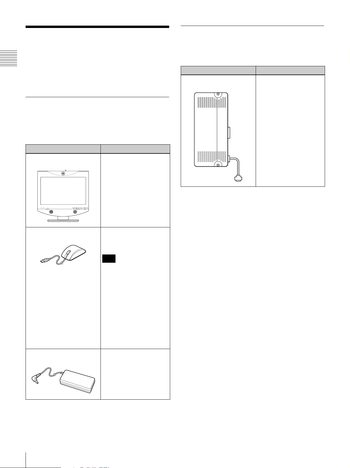
The ViewPoint 8050 Videoconferencing Terminal is
Chapter 1 Installation and Preparation
composed of basic system components for a basic
videoconference, and optional equipment for an enhanced
videoconference.
Basic System Components
The ViewPoint 8050 Videoconferencing Terminal is the
basic system of the Videoconferencing System. It contains
the following components:
Unit Description
ViewPoint 8050
Videoconferencing Terminal
Contains the camera,
display, video codec, audio
codec, echo canceller,
network interfaces and
system controller.
Optional Equipment
The following optional devices are used to enhance your
videoconference.
Unit Description
Dual Stream Box ViewPoint
8050-DSB
Serves for transmitting the
display image of a
connected computer and
also allows connection of a
projector for displaying the
computer image.
Optical mouse ViewPoint
8050-MS
SQ2N120W19P-01
AC adaptor
Serves for operation of the
Videoconferencing
Te r mi n al .
Note
Due to the nature of the
optical sensor, the mouse
may not operate properly on
transparent or reflective
surfaces (such as glass or
mirrors). If the mouse does
not operate properly, avoid
using these surfaces or use
a commercially available
optical mouse pad.
Depending on the color and
material of the mouse pad,
however, the mouse may
still not operate properly.
Supplies power to the
Videoconferencing
Te r mi n al .
16
System Components
Page 19
Names and Functions of
1 234
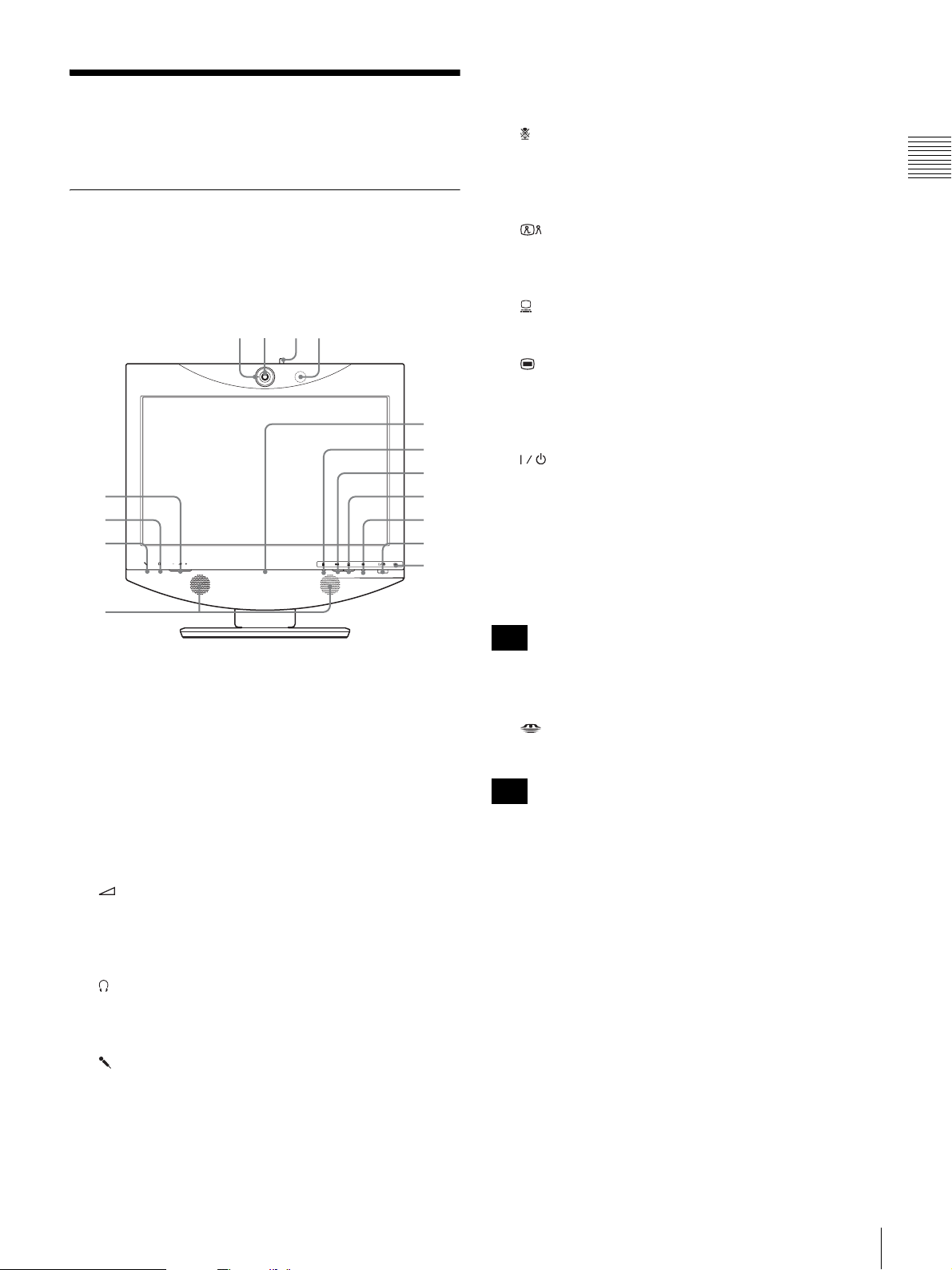
i Online lamp
Shows mainly the incoming/outgoing call status.
Parts
ViewPoint 8050 Videoconferencing Terminal
Front view
9
q;
qa
5
6
7
8
qs
qd
qf
qg
j (Mic Off) button and indicator
Lets you suppress the sound from the local system. Press
the button again to resume sending the sound to the remote
system.
k (Videoconference) button and indicator
Serves for switching from computer screen to
videoconference screen.
l (PC) button and indicator
Serves for switching to computer screen.
m (Menu) button
Press to bring up the Setup menu.
Press and hold this button for 3 seconds during communication
to bring up the DTMF soft keyboard on the screen.
n (Power) switch and indicator
Turns power to the system on and off.
When using the system as a computer screen in PC mode,
pressing the switch once turns the power off.
When using the system in videoconference mode, pressing
the switch once sets the system to standby mode. To turn
the power off in videoconference mode, press the switch
again within 5 seconds of the first press.
Note
Chapter 1 Installation and Preparation
a Tally lamp
Lights up when local video is being sent to the remote
system.
b Camera lens
c Lever for lens cover
Lets you close the camera lens.
d Microphone
e (Volume) buttons
Serve to adjust the volume.
+: Increases the volume level.
–: Decreases the volume level.
f (Phones) jack (stereo mini jack)
Allows connection of a pair of headphones (commercially
available).
g (Mic) jack (mini jack)
Allows connection of a microphone.
h Speakers
The power switch does not function during a
communication session.
o “Memory Stick” indicator
Shows the status of the “Memory Stick” slot.
Note
Do not remove the “Memory Stick” when this indicator is lit.
Names and Functions of Parts
17
Page 20
Rear view
7653421
Chapter 1 Installation and Preparation
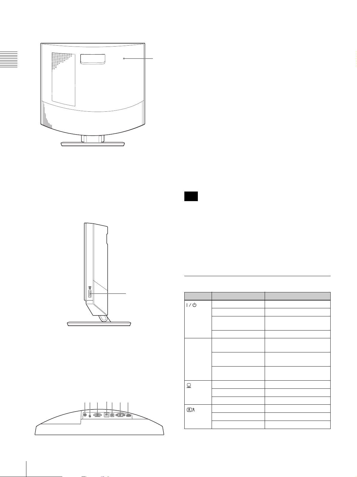
a Rear cover
Removing this cover gives access to the connector panel.
The connecting section between the stand and the display
is also located behind the panel. You can adjust the height
of the display by changing the screw positions.
1
a DC19.5V connector
Connect the supplied AC adapter SQ2N120W19P-01 here.
b AUDIO IN (PC sound input) jack (stereo mini
jack)
Connect this jack to the audio output of a computer
connected to the RGB IN connector.
c RGB IN connector (15-pin mini D-sub connector)
Connect the RGB output of a computer here.
d 100BASE-TX/10BASE-T port (modular port)
Use a Category 5 LAN cable to connect this port to a hub
or similar equipment.
This port is equipped with a Link/Data indicator (green)
and a 100/10 Mbps indicator (orange).
e PC port
This connector is used when the same mouse is to be used
for the ViewPoint 8050 and for a computer connected to
the RGB IN connector. Link the connector to a USB port
on the computer.
Note
Right side view
1
a “Memory Stick” slot
A “Memory Stick” can be inserted here.
Connector panel
(section behind rear cover, seen from
below)
Use a USB cable that is 3 m (10 ft.) or shorter.
f RS-232C port (9-pin D-sub connector)
This connector is used only for servicing the system.
g Mouse port
Connect the supplied optical mouse ViewPoint 8050-MS
here.
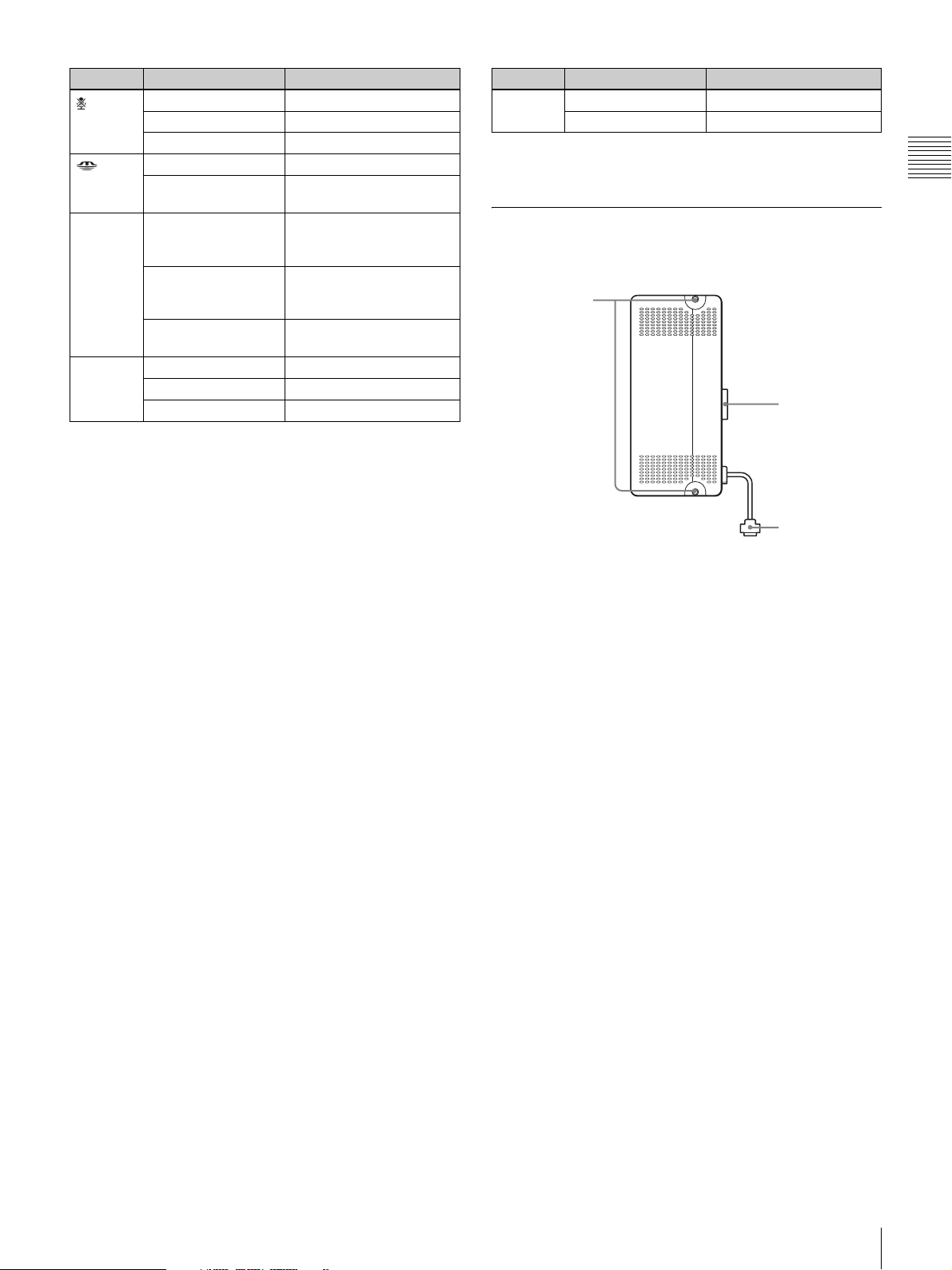
Indicator Names and Functions
Indicator Status Meaning
Lit green Power is on
(Power) *
Online * Flashing blue
(PC) *
(Videoconference) *
Lit orange Standby
Flashing orange (1-
second cycle)
Out Power is off
(3 times per sec.)
Blue illumination lit Communication in
Out Offline (no missed call) or
Lit blue Computer display
Lit white Videoconference display
Out Standby
Lit blue Videoconference display
Lit white Computer display
Out Standby
Problem with fan
Sending/receiving
progress
standby
18
Names and Functions of Parts
Page 21
Indicator Status Meaning
1
(Mic off) *
(“Memory
Stick”)
Tally lamp Lit orange Camera image being sent
Link/Data Lit green Link is established
Lit orange Mic off
Lit white Mic on
Out Standby
Lit orange
Out Not accessing “Memory
Flashing orange
(5-second cycle)
Out Camera image not being
Flashing green Data is transferring
Out Link is offline
Accessing “Memory Stick”
Stick”
to remote party (lens
cover open)
Closed image being sent
to remote party (lens
cover close)
sent
Indicator Status Meaning
100/
10 Mbps
* The indicator is lit while the system is starting up. If abnormal temperature
is detected, the indicator flashes and power turns off.
Lit orange 100 Mbps
Out 10 Mbps
ViewPoint 8050-DSB Dual Stream Box (Optional)
2
3
Chapter 1 Installation and Preparation
a Fastening screws
Used to secure the unit to the ViewPoint 8050.
b Monitor connector
Used to connect the unit to the ViewPoint 8050.
c RGB Output connector
Used to connect the unit to an external device, such as a
projector.
A commercially available RGB cable is required to use
this connector.
For information about installation in the ViewPoint 8050,
see “Installing the Dual Stream Box” on page 76.
Names and Functions of Parts
19
Page 22
System Connections
This section describes the typical system connections.
Chapter 1 Installation and Preparation
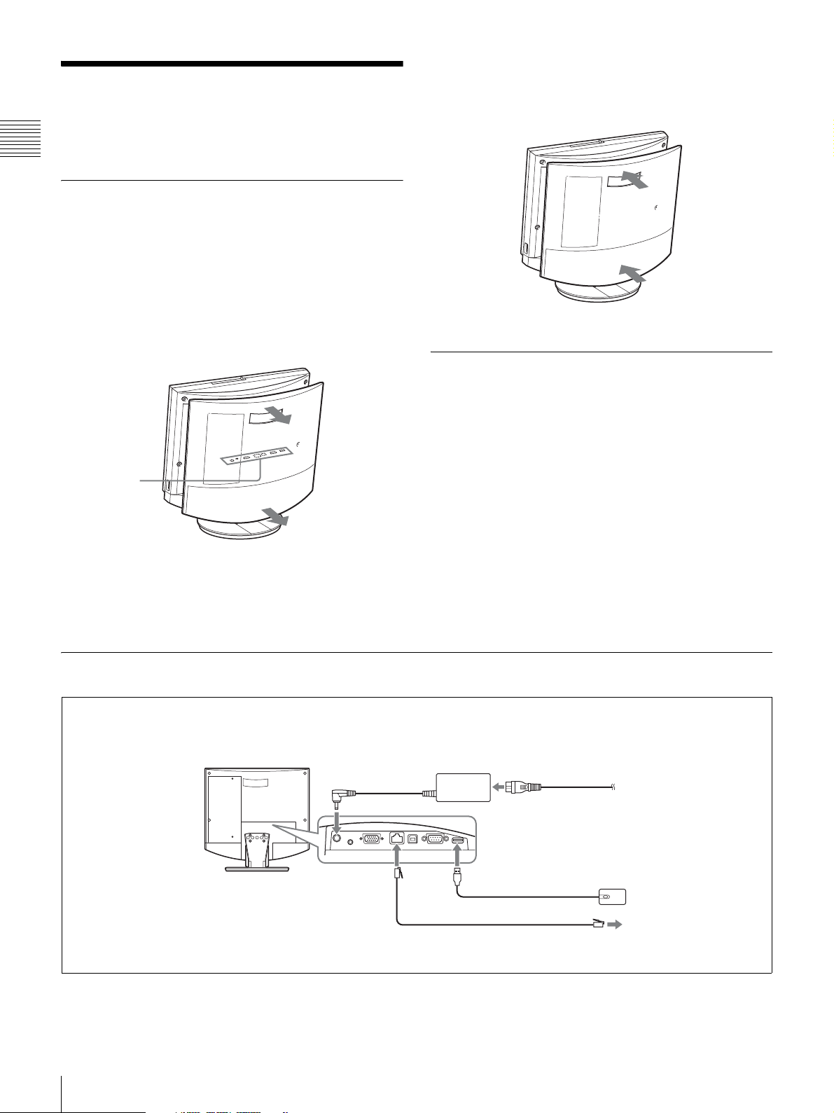
About the Connectors
The connectors of the system are located under the rear
cover. Remove the cover to make connections, and then
replace the cover again.
To remove the rear cover
Pull the rear cover toward you.
Connector
panel (under
rear cover)
To attach the rear cover
Push the cover in while aligning the four stubs.
Connection Precautions
Warning
• Use only the supplied AC adapter and power cord.
• When connecting the power cord of the AC adapter and
the DC cable, insert the plugs fully and securely.
• For safety, do not connect the 100BASE-TX/10BASE-T
connector to a network where excessive voltages may
occur.
Caution
• Before making any connections, be sure to turn power to
all components off.
• To prevent damage to the unit, do not plug in or
disconnect any cable while power to the unit is turned
on.
System Connection via a LAN
Make connections in the order 1 - 5.
Videoconferencing
Terminal ViewPoint 8050
To 100BASE-TX/ 2
10BASE-T port
3 To DC19.5V
connector
UTP cable Category 5 (straight cable, commercially available)
AC adapter SQ2N120W19P-01
(supplied)
4 Power cord (supplied)
1 To mouse port
5 To AC outlet
(120 V AC)
Optical mouse ViewPoint
8050-MS (supplied)
To LAN
20
System Connections
Page 23
Adjusting the Height of the Display
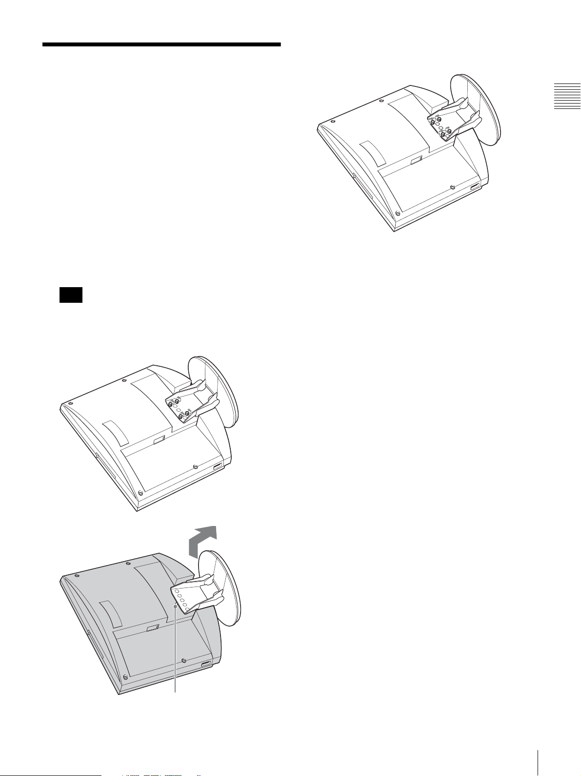
The stand and the display section of the ViewPoint 8050
are joined by fastening screws. There are three sets of
screw holes, spaced 25 mm apart. In the factory default
condition, the display is fixed in the lowest position. By
choosing a different set of screw holes, you can change the
height of the display.
1
Remove the rear cover of the unit.
For information on how to do this, see page 20.
2
Remove the 4 screws using a coin or similar object, lift
up the stand, and insert the positioning pin in the hole
for the new stand position.
Note
Before changing the height of the display as described
above, be sure to turn the power off. Place the display
face down on a soft cloth or similar.
3
Tighten the 4 screws using a coin or a similar object to
secure the stand.
4
Attach the rear cover again.
Chapter 1 Installation and Preparation
Positioning pin
Adjusting the Height of the Display
21
Page 24
Turning the System On/ Off
Chapter 1 Installation and Preparation
This section describes how to turn the Videoconferencing
Terminal on and off.
Before turning the system on, make sure that system
connections have been completed correctly.
For information on connecting the system, see the section
“System Connections” on page 20.
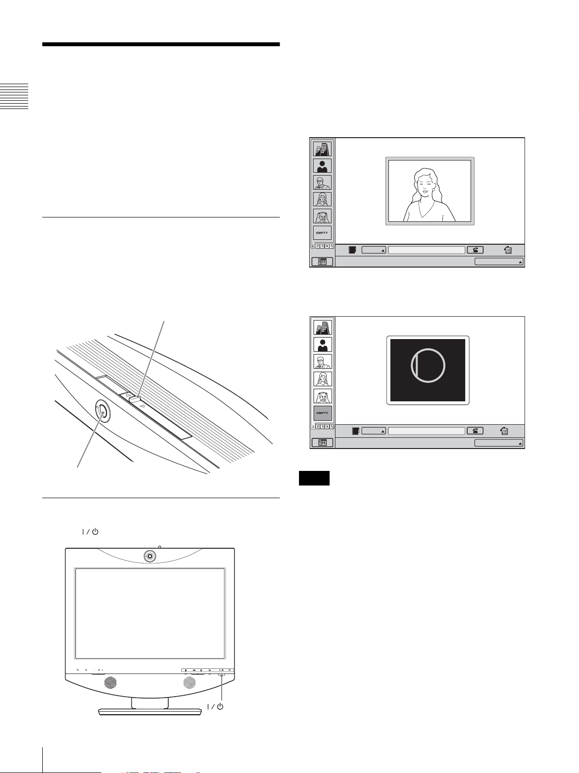
Opening the Lens Cover
The indicator of the switch lights up in orange and power
to the Videoconferencing Terminal comes on. When
powering on is complete, the indicator lights up in green.
The launcher menu appears on the display and the picture
of the local camera is also shown.
Launcher menu
The system is equipped with a lens cover to hide the
camera. Before starting a videoconference, open the lens
cover by sliding the lever for lens cover on the top of the
system to the right. If the lens cover is closed, the picture
on the local site will not be seen on the remote site.
Lever for lens cover
Camera
Turning the System On
Press the (Power) switch on the ViewPoint 8050.
IP
Click Icon to go into the function.
IP:
012.345.678.912
When the lens cover is closed, the launcher menu appears
as follows.
CLOSED
Closed
IP
Click Icon to go into the function.
Notes
IP:
012.345.678.912
• The first time the power switch is pressed after the power
cord is plugged into a wall outlet, it may take as long as ten
seconds for the indicator on the switch to light up.
• When you turn on power to the Videoconferencing
Terminal for the first time after installation, the setup
wizard will appear. Set up your system following the
wizard.
22
Turning the System On/Off
(Power) switch
For information on the setup procedure using the
wizard, see “Setting Up the System for the First Time —
Initial Setup Wizard” on page 24.
• When an optional device especially designed for use with
this system, such as the Dual Stream Box, is connected for
the first time, the Videoconferencing Terminal may
automatically upgrade the software of the connected device.
While the upgrading message is displayed, be sure not to
turn off the Videoconferencing Terminal. Doing so may
cause malfunction of the system. System malfunction may
Page 25

also occur when a system power-off has been caused by an
accidental problem such as a power interruption during
upgrading. If the Dual Stream Box or other equipment is not
recognized properly after power is restored, consult a
HUAWEI dealer.
Turning the System Off
Adjusting the Picture Quality
Use the Display Setup menu to adjust the picture quality.
For details, see the section “Adjusting the Picture Quality
on the Display” on page 84.
Chapter 1 Installation and Preparation
1
Press the (Power) switch twice.
After pressing the switch once, the message “To enter
standby mode, wait for a few moments. To turn off the
power, press the power switch again.” appears. Press
the power switch again.
2
Turn off the power of other equipment used for the
videoconference.
Notes
• Turn the power to the system off when the system
will not be used for an extended period. While the
power is off, you cannot receive a call from a remote
party.
• When using the system as a computer display in PC
mode, the power turns off with one press of the
power switch.
• During a conference, the power switch does not
function.
Setting the Videoconferencing
Displaying Help
Move the mouse cursor to the item you want to check, and
right-click the mouse to display context-specific help
window.
Displaying Version and Option Information
You can check version information for Videoconferencing
Terminal, any dedicated optional equipment, and the
software by displaying the Status & Info menu.
For details on the Status & Info menu, see “Status & Info
Menu” on page 55.
Terminal to Standby Mode
When you press the (Power) switch on the ViewPoint
8050, the message “To enter standby mode, wait for a few
moments. To turn off the power, press the power switch
again.” appears on the display. If you do not click the
“Cancel” button, the system will go into standby mode.
You can receive a call from a remote party in the standby
mode.
To return to normal mode from standby mode, press the
power switch once.
Adjusting the Volume
Press the (Volume) button on the ViewPoint 8050 to
set the volume level as required.
Note
The volume can be adjusted separately for the
videoconference and for the computer display.
Turning the System On/Off
23
Page 26
Setting Up the System for
the First Time — Initial
Setup Wizard
Chapter 1 Installation and Preparation
Design and specifications are subject to change without
notice.
When you turn on the Videoconferencing Terminal for the
first time after installation, the setup wizard appears on the
display.
The items configured with the wizard can be changed later
using the setup menu.
Configuration items may differ depending on the software.
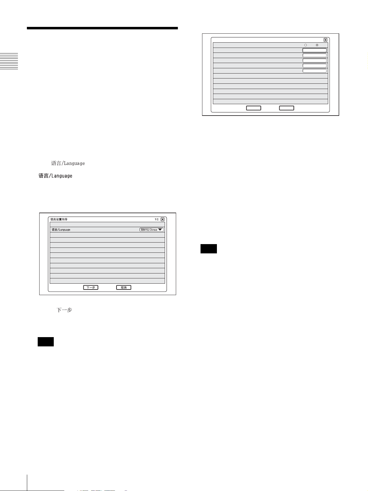
1
Select the language used for menus and messages from
the “ ” pull-down list.
: Available settings are English, Finnish,
French, German, Italian, Japanese, Korean,
Portuguese, Russian, Simplified Chinese, Spanish,
Swedish, Thai, and Traditional Chinese.
DHCP Mode
Host Name
IP Address
Network Mask
Gateway Address
DNS Address
End
Back
2/2
Auto Of f
DHCP Mode: Sets the DHCP (Dynamic Host
Configuration Protocol).
Auto: Automatically assigns your IP address,
subnet mask, gateway address and DNS
address.
Off: Deactivates DHCP. In this case you must set
your IP address, subnet mask, gateway
address and DNS address manually.
Host Name: Enter your host name.
IP Address: Enter your IP address.
Network Mask: Enter your subnet mask.
Gateway Address: Enter your default gateway
address.
DNS Address: Enter your DNS (Domain Name
System) server address.
2
Click “ ”.
3
Make the following settings for the LAN.
Note
The following examples assume that English has been
selected as display language.
Note
When you set “DHCP Mode” to “Auto”, the assigned
IP address will be shown in the launcher menu (page
26) and Status & Info menu (page 55).
If you do not know the settings required for your LAN
configuration, contact your network administrator.
4
Click “End”.
The settings are saved.
To cancel the setting
Click “Cancel”.
The settings are not saved and the launcher menu appears.
To go back to the previous wizard
Click “Back”.
24
Setting Up the System for the First Time — Initial Setup Wizard
Page 27
Using the Menu
The Videoconferencing Terminal uses the on-screen
menus to make various adjustments and settings. This
section gives a brief introduction of the menus.
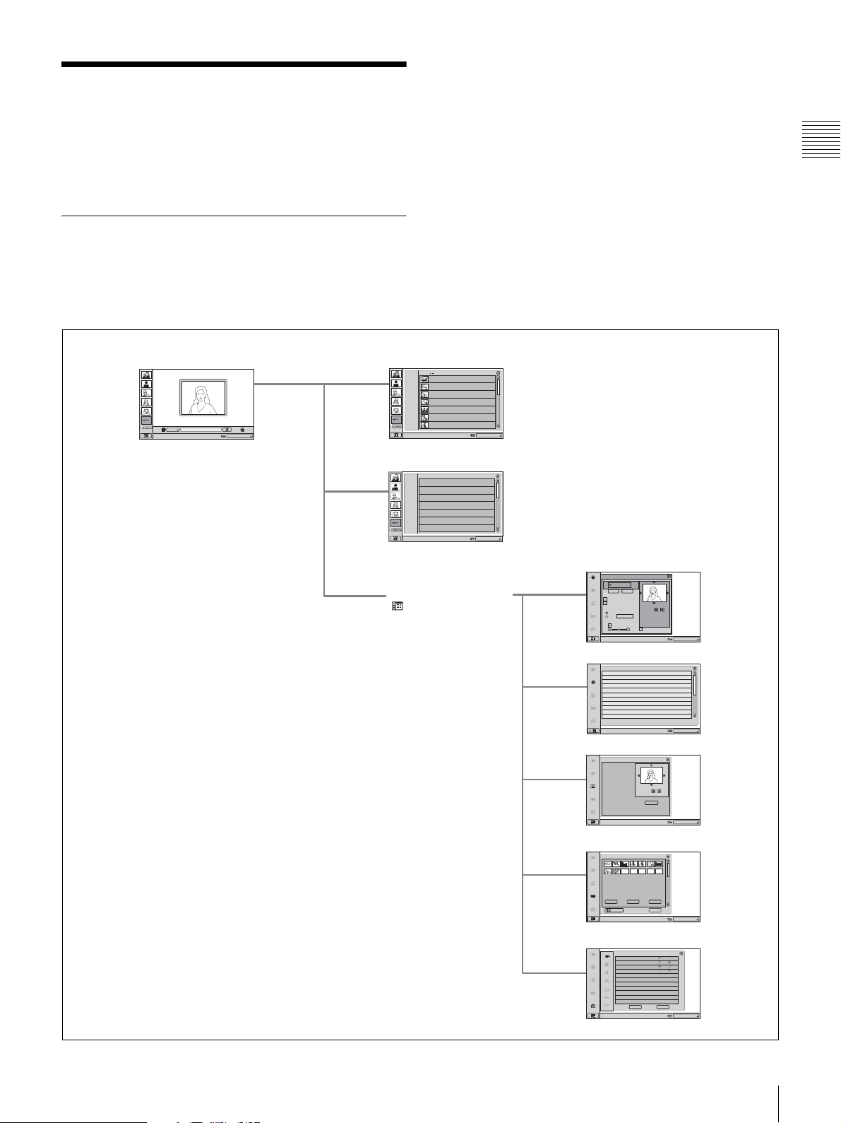
Menu Configurations
The menus of this system configure as described below.
For more detailed menu configurations, refer to “Menu
Configuration” on page 117.
Launcher menu Phone Book/Private Phone Book menu
IP
Point to and click on the icon with the mouse.
IP:
012.345.678.912
IP:
012.345.678.912
1/3
Phone Book 0
ALL
HQ4Room5
A-I
AUTO
05032105678
J
-
S
Takanawa
0657896709
-
Z
T
HQ5Room6
-
9
0
XXXXXXXXXX
New
HQ5Room6
XXXXXXXXXX
HQ5Room6
XXXXXXXXXX
HQ5Room6
XXXXXXXXXX
HQ5Room6
XXXXXXXXXX
Right-click the mouse to display a help message.
History menu
IP:
012.345.678.912
1/3
History
ALL
2005.07.30 10:10
OUT
IN
05032105678
IN
2005.07.30 10:10
OUT
0657896709
2005.07.30 10:10
OUT
XXXXXXXXXX
2005.07.30 10:10
IN
XXXXXXXXXX
2005.07.30 10:10
OUT
XXXXXXXXXX
2005.07.30 10:10
IN
XXXXXXXXXX
2005.07.30 10:10
IN
XXXXXXXXXX
Right-click the mouse to display a help message.
Menu bar display button
Camera Control menu
Camera Control
Preset
Save Load
Backlight Compensation
Flicker Removal
White Balance
Zoom
Auto
Adjust now
Adjust
Brightness Adjust
Auto Adjust
Control by Far End
IP:
Right-click the mouse to display a help message.
012.345.678.912
Status & Info menu
Status & Info.
Ver XX.XX
Host Version
Ver XX.XX
DSP Version
Ver XX.XX
LCD software version
Ver XX.XX
Camera version
Ver XX.XX
AEC version
DSM version
Ver XX.XX
XXXXXX
Host Name
IP Address
XXX.XXX.XXX.XXX
MAC Address
XX:XX:XX:XX:XX:XX
XXXX
Serial Number
Communication Status
Disconnecting
OK
Cancel
IP:
Right-click the mouse to display a help message.
012.345.678.912
Still Image menu
Still Image
Chapter 1 Installation and Preparation
1/2
Zoom
Save
Right-click the mouse to display a help message.
IP:
Image Viewer menu
Image viewer
Load
Format
Right-click the mouse to display a help message.
Send Delete
1/3
Close
IP:
Setup menu
Answer
Auto Answer
Videoconference Button Answer
Mic on Answer
Do not disturb
Right-click the mouse to display a help message.
CancelOK
On Off
On Off
On Off
On Off
IP:
012.345.678.912
012.345.678.912
012.345.678.912
Using the Menu
25
Page 28
Menu Icons
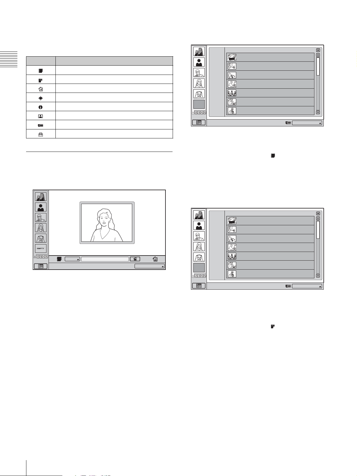
Selecting an icon shown on the screen displays the
respective menu.
Icon Displayed menu
Chapter 1 Installation and Preparation
Phone Book menu
Private Phone Book menu
History menu
Camera Control menu
Status & Info menu
Still Image menu
Image Viewer menu
Setup menu
Explanation of Menus
Phone Book menu
ALL
A-I
-
S
J
-
Z
T
-
9
0
New
EMPTY
Right-click the mouse to display a help message.
Phone Book
AUTO
HQ4Room5
05032105678
Takanawa
0657896709
HQ5Room6
XXXXXXXXXX
HQ5Room6
XXXXXXXXXX
HQ5Room6
XXXXXXXXXX
HQ5Room6
XXXXXXXXXX
HQ5Room6
XXXXXXXXXX
1/3
IP:012.345.678.912
The Phone Book menu is used to register a remote party,
and to call a registered remote party.
The menu appears when you click in the launcher menu.
Launcher menu
IP
Click Icon to go into the function.
IP:
012.345.678.912
The launcher menu appears when the Videoconferencing
Terminal is turned on, and when the system is not
connected to a remote party.
The left side of the screen displays the One Touch Dial
buttons, which give access to the One Touch Dial function,
and the Menu Bar display button.
For details on the launcher menu, see pages 53 - 57.
For details on the One Touch Dial function, see pages 46
and 56.
For details on the Phone Book menu, see pages 41 - 45 and
57 - 58.
Private Phone Book menu
ALL
A-I
-
S
J
-
Z
T
-
9
0
New
EMPTY
Right-click the mouse to display a help message.
Private Phone Book
HQ4Room5
AUTO
05032105678
Takanawa
0657896709
HQ5Room6
XXXXXXXXXX
HQ5Room6
XXXXXXXXXX
HQ5Room6
XXXXXXXXXX
HQ5Room6
XXXXXXXXXX
HQ5Room6
XXXXXXXXXX
1/3
IP:012.345.678.912
The Private Phone Book menu can be used when a
“Memory Stick” with a personal (private) phone book
saved on to it is inserted into the memory stick slot.
The menu appears when you click in the launcher menu.
For details on the Private Phone Book menu, see pages 43
- 44, 57 and 58.
26
Using the Menu
Page 29
History menu
The menu appears when you click “Camera Control” on
the menu selection screen.
History
ALL
OUT
IN
Right-click the mouse to display a help message.
IN
OUT
OUT
IN
OUT
IN
IN
2005.07.30 10:10
05032105678
2005.07.30 10:10
0657896709
2005.07.30 10:10
XXXXXXXXXX
2005.07.30 10:10
XXXXXXXXXX
2005.07.30 10:10
XXXXXXXXXX
2005.07.30 10:10
XXXXXXXXXX
2005.07.30 10:10
XXXXXXXXXX
1/3
IP:012.345.678.912
Serves for checking the transmission history of incoming
and outgoing calls.
To bring up the menu, click in the launcher menu.
For details on the History menu, see page 45.
Settings menu selection screen
For details on the Camera Control menu, see pages 62 -
64.
Status & Info menu
Status & Info.
Host Version
DSP Version
LCD version
Camera version
AEC version
DSM Version
Host Name
IP Address
MAC Address
Serial Number
Communication Status
OK
Right-click the mouse to display a help message.
Ver XX.XX
Ver XX.XX
Ver XX.XX
Ver XX.XX
Ver XX.XX
Ver XX.XX
XXXXXX
XXX.XXX.XXX.XXX
XX:XX:XX:XX:XX:XX
XXXX
Disconnecting
Cancel
1/2
IP:012.345.678.912
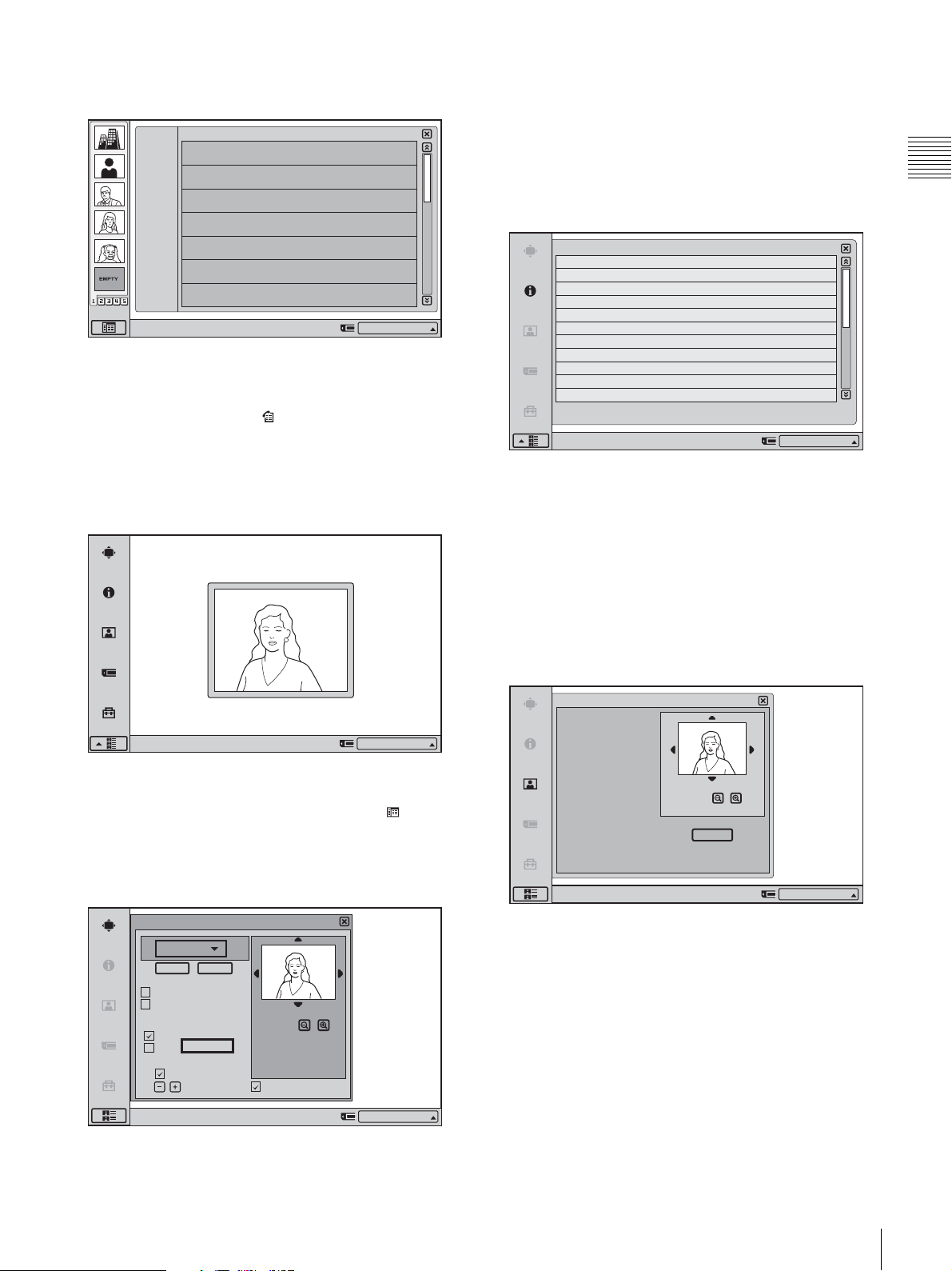
Shows version information about the ViewPoint 8050 and
connected dedicated optional equipment, as well as for the
software options being used.
The menu appears when you click “Status & Info” on the
menu selection screen.
Chapter 1 Installation and Preparation
Right-click the mouse to display a help message.
IP:012.345.678.912
Allows you to access menus for various settings.
The settings menu bar appears when you click (menu
bar display) in the bottom left of the launcher screen.
Camera Control menu
Camera Control
Preset
Save Load
Backlight Compensation
Flicker Removal
White Balance
Auto
Adjust
Brightness Adjust
Auto Adjust
Start
Zoom
Control by Far End
For details on the Status & Info menu, see page 55.
Still Image menu
Still Image
Zoom
Save
Right-click the mouse to display a help message.
IP:012.345.678.912
Serves to control the still image functions.
The menu appears when you click “Still Image” on the
menu selection screen.
For details on the Still Image menu, see pages 70 - 72.
Right-click the mouse to display a help message.
IP:012.345.678.912
Allows you to control the camera angle and zoom.
Using the Menu
27
Page 30
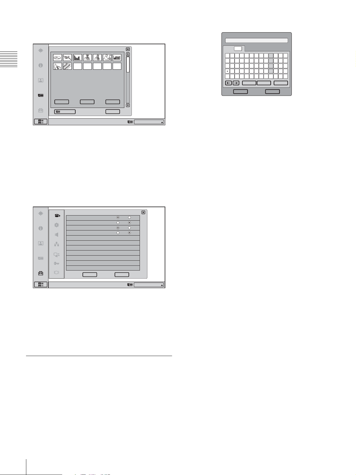
Image Viewer menu
Dial Number
Image viewer
1/3
Chapter 1 Installation and Preparation
Load
Format
Right-click the mouse to display a help message.
Send Delete
Close
IP:012.345.678.912
Allows you to display and transmit images stored on a
“Memory Stick”.
The menu appears when you click “Image Viewer” on the
menu selection screen.
For details on the Image Viewer menu, see pages 67 - 68.
Setup menu
Answer Setup
Auto Answer
Videoconference Button Answer
Mic on Answer
Do not disturb
On Off
On Off
On Off
On Off
ABC A/a
Delete all
/
$
Cancel
123
45
7869
0
,
.
<>
%
Space
ABCDEFGH I
JKl MNOPQR
STUVWXYZ "
#
@_ & : ; - /
~
^() !?
+=
Backspace
OK
In situations where alphanumeric text input is required, for
example when a text field in a menu is selected, a soft
keyboard appears. If only numerals and symbols can be
entered, a numeric keypad appears.
To enter alphanumeric characters and symbols
Click the “ABC” tab on the soft keyboard and click on the
character or symbol to enter. The “A/a” button toggles
between upper and lower case.
To confirm the alphanumeric characters and
symbols entered
After clicking the alphanumeric characters and symbols
you wish to enter, click “OK”. The entry is set, and the soft
keyboard closes.
If you have made a mistake
Click the “Backspace” button on the soft keyboard, and the
character or symbol before the cursor will be erased. If you
click “Delete all”, all the characters and symbols will be
erased.
CancelOK
Right-click the mouse to display a help message.
IP:012.345.678.912
Allows the administrator to make various detailed settings
for the system.
The menu appears when you click “Setup” on the menu
selection screen.
For details on the Setup menu, see pages 29 - 41.
Entering Characters
This section explains how to enter letters, numerals or
symbols into the text fields in the menu using the soft
keyboard.
28
Using the Menu
Page 31
Registration and Setup
Chapter
2
Chapter 2
This chapter describes the general registration and settings
procedures.
Registering Local Information
Before starting a conference, register the required
information on the local terminals of the system using the
Setup menu. This section describes how to display the
Setup menus and gives a introduction to the menus.
Opening the Setup Menu
1
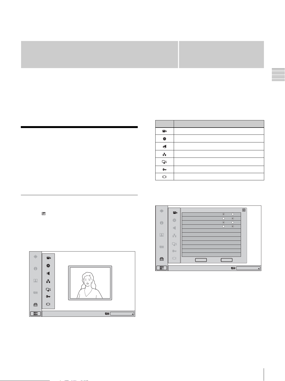
Click (menu bar display) on the launcher menu.
The menu bar appears.
2
Click “Setup” on the menu bar.
Submenus available from the Setup menu
Selecting the respective item brings up the following
menus.
Icon Displayed menu
Answer Setup menu (page 30)
Device Setup menu (page 30)
Audio Setup menu (page 31)
Network Setup menu (page 32)
Communication Mode menu (page 33)
Administrator Setup menu (pages 35)
Display Setup menu (page 39)
3
Click the button for the menu you want to access.
The selected menu appears.
Answer Setup
Auto Answer
Videoconference Button Answer
Mic on Answer
Do not disturb
On Off
On Off
On Off
On Off
Registration and Setup
The Setup menu appears.
Right-click the mouse to display a help message.
IP:012.345.678.912
CancelOK
Right-click the mouse to display a help message.
4
Set the respective items.
For details on setting items, see the page for the
respective menu (pages 30 - 41).
5
When the setting is completed, click “OK”.
The setting is saved, and the Setup menu appears
again.
To cancel the setup procedure
Click “Cancel”.
Registering Local Information
IP:012.345.678.912
29
Page 32
To page up or down the selected menu
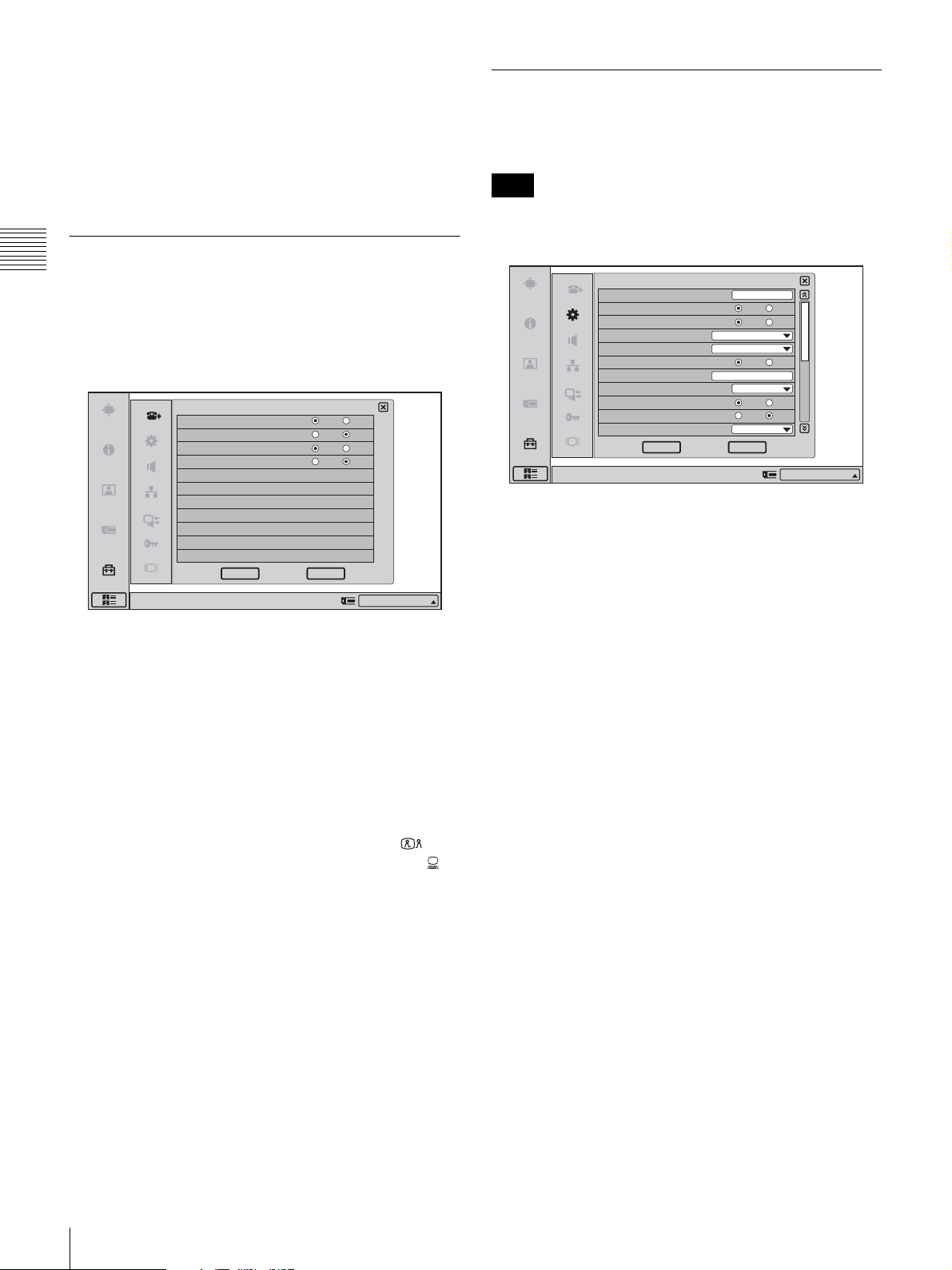
When a menu has several pages, a scroll bar will appear at
the right side of the screen. To advance to the next page,
click the Page button at the bottom of the scroll bar. To go
back to the previous page, click the Page button at the top
of the scroll bar. You can also drag the scroll bar up and
down using the mouse to scroll through the pages.
Answer Setup Menu
Chapter 2
The Answer Setup menu is used to set the system up for
receiving a call.
Registration and Setup
Page 1/1
Answer Setup
Auto Answer
Videoconference Button Answer
Mic on Answer
Do not disturb
On Off
On Off
On Off
On Off
CancelOK
Device Setup Menu
Page 1/2
Note
Some items cannot be set while a communication session
is in progress.
Device Setup
Terminal Name
Time Display
Last Number Registration
Language
Number Display
Indicator
Clock Set
Sleep Timer
LED indicator
Lens Cover Mic On/Off Function
Camera Frame Rate
Right-click the mouse to display a help message.
English
IP:
04/18/2005 16:58:00
Off
Auto
Terminal Name
Input the terminal name to report when the system is
connected to an external multipoint videoconferencing
system.
1/2
ViewPont 8050
On Off
ON Off
On Off
On Off
On Off
CancelOK
IP:012.345.678.912
Right-click the mouse to display a help message.
IP:012.345.678.912
Auto Answer
Select whether the auto answer mode is activated.
On: Answers a call in auto answer mode. When a call
comes in and the phone rings, the line is automatically
connected.
Off: Answers a call in manual answer mode. When you are
called up, the phone rings. If you click “OK” when the
message “Incoming call. Answer?” is shown, the line
is connected.
Videoconference Button Answer
Select whether to enable call answering with the
(Videoconference) button and call rejection with the
(PC) button when Auto Answer is disabled.
On:
Enables answer operations with the buttons on the unit.
Off:
Disables answer operations with the buttons on the
unit.
Mic on Answer
Select whether to transmit the sound on your site when
answering a call from the remote party.
On: Transmits the sound when answering a call.
Off: Disables transmission of the sound when answering a
call.
Do not disturb
Select whether to reject all calls.
On: Reject all incoming calls.
Off: Do not reject incoming calls.
Time Display
Select whether to show the elapsed time on the display
during the videoconference.
On: Elapsed time is displayed.
Off: Elapsed time is not displayed.
Last Number Registration
Select whether or not to register the remote party in the
Phone Book after the videoconference has finished.
On: If the remote party has not yet been registered in the
Phone Book, the message “Register this participant in
the list?” appears on the display after the
videoconference has finished. When you click “OK”,
the List Edit menu opens.
Off: The above message does not appear.
Language
Select the language to show on the screen.
English: The display language is set to English.
Finnish: The display language is set to Finnish.
French: The display language is set to French.
German: The display language is set to German.
Italian: The display language is set to Italian.
Japanese: The display language is set to Japanese.
Korean: The display language is set to Korean.
Portuguese: The display language is set to Portuguese.
Russian: The display language is set to Russian.
Simplified Chinese: The display language is set to
Simplified Chinese.
Spanish: The display language is set to Spanish.
Swedish: The display language is set to Swedish.
30
Registering Local Information
Page 33
Thai: The display language is set to Thai.
Traditional Chinese: The display language is set to
Traditional Chinese.
Number Display
Select the information to display as identification for your
system in the launcher menu, such as IP information.
IP: Displays your IP address.
GK: User Alias: Displays the registered gatekeeper user
alias when using gatekeeper.
GK: User Number: Displays the registered gatekeeper
user number when using gatekeeper.
NAT: Address: Displays the NAT address when
connected to a network using NAT.
No display: Does not display any IP information.
Indicator
Select whether the packet loss, mic gain, sending/receiving
still image, sending/receiving DSB data, transmission
mode, and network congestion indicators are shown.
On: Indicators are shown.
Off: Indicators are not shown.
Off: Opening and closing of the lens cover does not affect
the mic.
Camera Frame Rate
Select the camera frame rate.
Auto: Automatically adjusts according to the illumination
of the ambient environment.
15fps: Transmit at a rate of 15 frames per second.
30fps: Transmit at a rate of 30 frames per second.
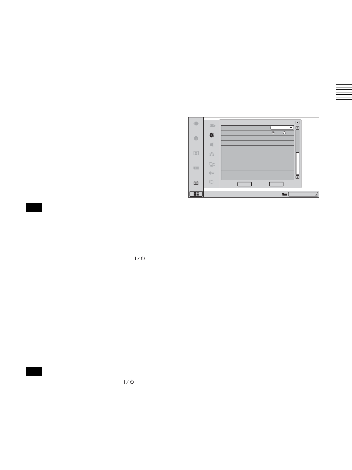
Page 2/2
Device Setup
Display Ter minal Name
Communication Taskbar Display
Show temporarily
2/2
On Off
Chapter 2
Registration and Setup
Clock Set
Enter the current date and time.
Note
If the AC adapter is left unplugged for more than 24 hours,
the date and time setting will be cleared.
Sleep Timer
Select the time interval until the standby condition is
automatically activated.
The standby condition is released when the (Power)
switch is pressed or a call is received.
5 min.: The standby condition is activated when there has
been no activity for 5 minutes.
15 min.: The standby condition is activated when there
has been no activity for 15 minutes.
60 min.: The standby condition is activated when there
has been no activity for 60 minutes.
Off: The standby condition is not activated automatically.
LED Indicator
Select whether the LED indicators of the system are
operative or not.
On: LED indicators will light.
Off: LED indicators will not light.
Note
CancelOK
Right-click the mouse to display a help message.
IP:012.345.678.912
Display Terminal Name
Allows you to select whether to display the connected
terminal names on the monitor screen.
Off: Not to display the terminal names.
Show temporarily: Display the terminal names for a
brief moment.
Always show: Display the terminal names.
Communication Taskbar Display
Select whether to display the taskbar during
communication.
On: Displays the taskbar during communication.
Off: Does not display the taskbar during communication.
Audio Setup Menu
The Audio Setup menu is used to set various audio items.
Page 1/1
The level meter indicating the audio input level is
displayed.
Even if the “Off” setting is chosen, the (Power)
indicator remains lit.
Lens Cover Mic On/Off Function
Select whether the mic turns on or off based on whether the
lens cover is open or closed.
On: When the lens cover is closed, the mic turns off.
Registering Local Information
31
Page 34
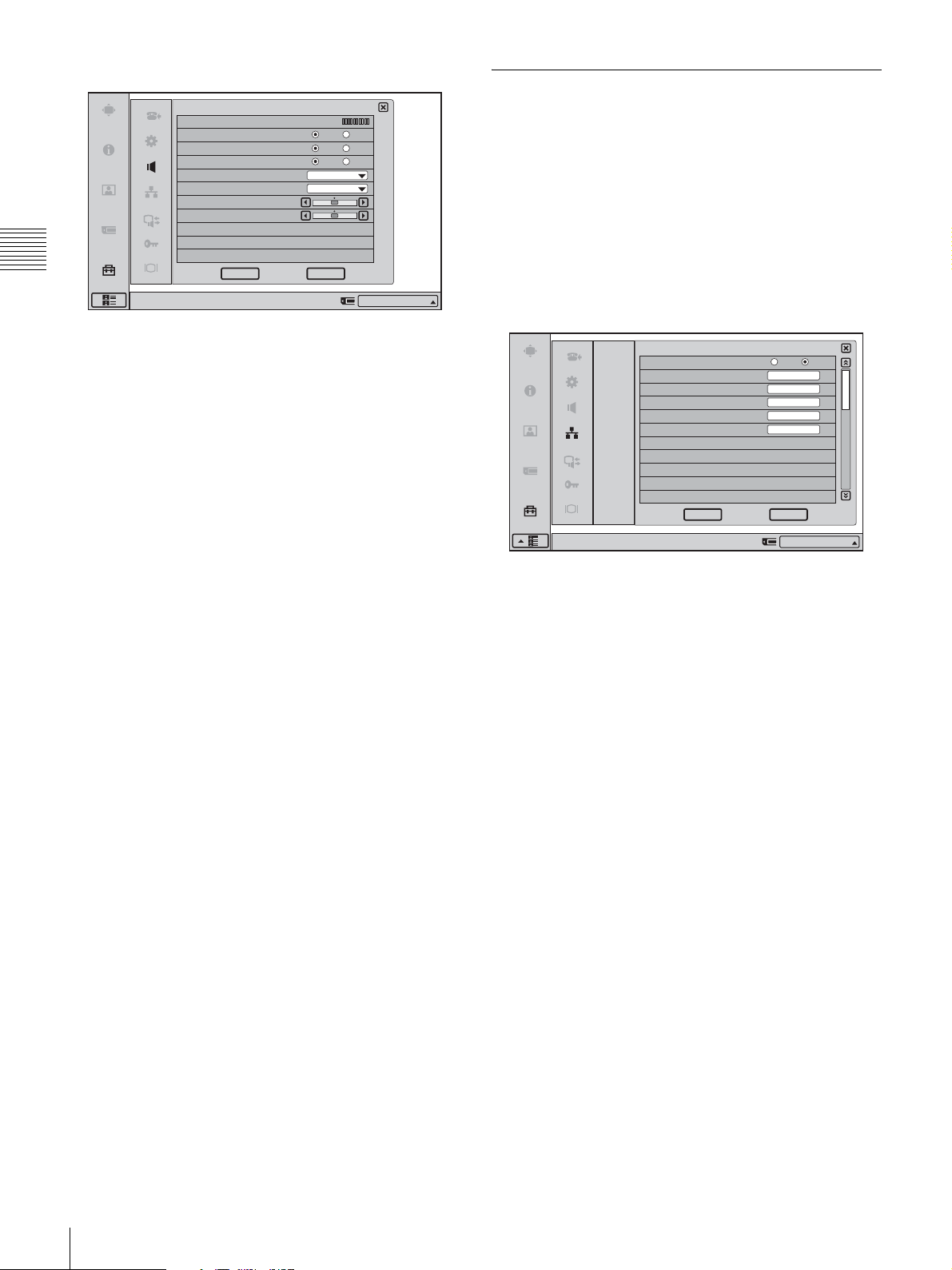
Audio Setup
Mic Lavel Meter
Beep Sound
Sound Effect
Dial Tone
Ringer Level
Headphone Ringer Level
PC Volume
Call Volume
On Off
On Off
On Off
Min
Min
Network Setup Menu
Lets you make LAN related settings.
For details on the settings, consult with the network
administrator.
For details on setting up each network using LAN, see
“Setting Up the Network Configurations” on page 47.
Chapter 2
Right-click the mouse to display a help message.
Registration and Setup
CancelOK
IP:012.345.678.912
Beep Sound
Selects whether the beep sounds when you perform a
mouse operation.
On: Enables beep.
Off: Disables beep.
Sound Effect
Selects whether or not to output the sound when the system
starts up, a videoconference starts, or a videoconference
ends.
On: Outputs the sound.
Off: Does not output the sound.
Dial Tone
Selects whether or not to output a dial tone when you are
dialing.
On: Outputs the dial tone.
Off: Does not output the dial tone.
Ringer Level
Selects the ringer volume when you receive a call.
To disable the ringer tone, select the “Off” setting.
To use the ringer tone, select one of the following settings:
“Min”, “Mid”, “Loud”.
Headphone Ringer Level
Use this item to select the headphone ringer volume for
incoming calls.
To disable the ringer tone, select the “Off” setting.
To use the ringer tone, select one of the following settings:
“Min”, “Mid”, “Loud”.
LAN Page 1/3
LAN
LAN
DHCP Mode
Host Name
IP Address
Network Mask
Gateway Address
DNS Address
Right-click the mouse to display a help message.
DHCP Mode
Selects whether DHCP (Dynamic Host Configuration
Protocol) server is enabled or not.
Auto: The IP address and subnet mask are automatically
assigned.
In this case, confirm the assigned IP address, subnet
mask, gateway address, and DNS address in the
launcher menu or the Machine Information menu after
the LAN connection is completed.
Off: Sets “DHCP Mode” to “Off”. In this case, enter the IP
address, subnet mask, gateway address, and DNS
address.
Host Name
Enter the host name.
IP Address
Enter the IP address.
1/3
Auto
Off
CancelOK
IP:012.345.678.912
PC Volume
Use this item to set the speaker/headphone volume for the
computer display.
Call Volume
Use this item to set the speaker/headphone volume for
videoconferences.
32
Registering Local Information
Network Mask
Enter the subnet mask.
Gateway Address
Enter the default gateway address.
DNS Address
Enter the DNS (Domain Name System) address.
Page 35
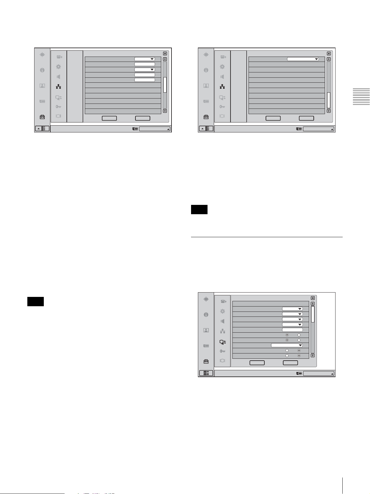
LAN Page 2/3
LAN Page 3/3
LAN
LAN
NAT Mode
WAN IP Address
Port Number Used
TCP Port Number
UDP Port Number
Right-click the mouse to display a help message.
Off
Default
2/3
CancelOK
IP:012.345.678.912
NAT Mode
Selects whether you connect the system to a local network
using NAT (Network Address Translation) that enables
sharing of one global IP address for multiple computers on
the same LAN.
Auto (UPnP): Enables the UPnP function.
On: Enables NAT mode.
Off: Disables NAT mode.
WAN IP Address
Enter the IP address of a global network to be used for
NAT mode.
LAN
LAN
NAT/Firewall Traversal
Right-click the mouse to display a help message.
Off
3/3
CancelOK
IP:012.345.678.912
NAT/Firewall Traversal
Allows you to select whether to use H.460 to traverse
firewalls and conduct conferences with terminals on other
networks.
On (H.460): Enables conferences that traverse H.460
standard firewalls.
Off: Disables conferences that traverse firewalls.
Note
You must set up the gatekeeper to use this function.
Chapter 2
Registration and Setup
Port Number Used
Selects whether or not to fix the TCP port number and
UDP port number.
Custom: Uses the port numbers set by the user.
Default: Uses the default port numbers.
TCP port number: 2253 - 2255
UDP port number: 49152 - 49239
Note
When “Port Number Used” is set to “Default” after it has
been set to “Custom”, restart the system to reset the setting.
TCP Port Number
When “Port Number Used” is set to “Custom”, enter the
TCP port number.
The display shows usable port numbers.
UDP Port Number
When “Port Number Used” is set to “Custom”, enter the
UDP port number.
The display shows usable port numbers.
For details on the port numbers used, see “List of Port
Numbers Used on the ViewPoint 8050” on page 113.
Communication Mode Menu
Lets you make communication related settings.
Page 1/2
Communication
Dial
Video Mode
Video Frame
Audio Mode
LAN Bandwidth
Input LAN Bandwidth
Far End Camera Control
H.239(Presentation)
Line I/F
Lip Sync
More Options Enable
Right-click the mouse to display a help message.
Auto
15fps
Auto
1024kbps
IP:
Dial
Video Mode
Select the compression method to be used for transmitting
video information.
Auto: Match the method selected at the far-end system.
H.264: Use H.264 compliant compression.
MPEG4: Use MPEG4 compliant compression.
H.263+: Use H.263+ compliant compression.
1/2
On Off
On Off
On Off
On Off
CancelOK
IP:012.345.678.912
Registering Local Information
33
Page 36
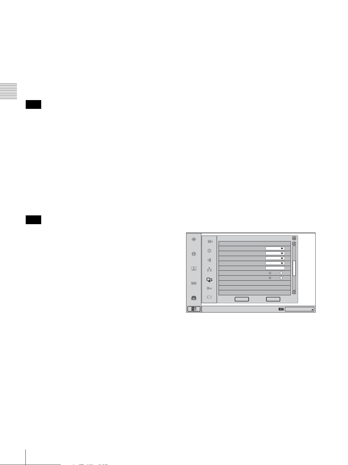
H.261: Use H.261 compliant compression (for still image
transmission [see Annex D]).
IP: Connect to a videoconferencing system on the remote
site via a LAN.
Video Frame
Select the send video frame rate.
Auto: The frame rate adjusts automatically.
15fps: Send CIF format video at a maximum rate of 15
frames per second.
30fps: Send CIF format video at a maximum rate of 30
frames per second.
Chapter 2
Note
If the video frame rate is set to 30fps when the camera
frame rate is set to 15fps or Auto, the actual frame rate of
Registration and Setup
the picture may be 15fps, depending on the usage
environment.
Audio Mode
Select an audio compression method.
Auto: Match the audio mode selected at the far-end
system.
MPEG4 Audio: Use MPEG4 compliant compression.
G.722: Use G.722 compliant compression.
G.729: Use G.729 compliant compression.
G.728: Use G.728 compliant compression.
G.711: Use G.711 compliant compression.
Lip Sync
Select whether to enable the Lip Sync function for
synchronizing the lip movement and audio of the
transmission source.
On: Enable the Lip Sync function.
Off: Disable the Lip Sync function.
More Options Enable
When “More Options Enable” is set to “On”, dial settings
for entries in the Phone Book and Private Phone Book can
be configured individually.
On: “More Options” appears in the List Edit menu of the
Phone Book and Private Phone Book, and you can
click on it to configure Video Mode, Video Frame,
Audio Mode, Far End Camera Control, and H.239
(Presentation) settings. You can configure these dial
settings for each individual entry.
The Dial settings configured in the Communication
Mode menu are applied to entries that have not been
configured with More Options.
Off: The Dial settings configured in the Communication
Mode menu are applied to all entries in the Phone
Book and Private Phone Book.
Note
If the far-end videoconferencing system does not support
the audio compression method selected at the ViewPoint
8050, the G.711 method will automatically be used.
LAN Bandwidth
Select the bandwidth to be used for transmission.
Available settings are 64 kbps, 128 kbps, 256 kbps, 384
kbps, 512 kbps, 768 kbps, 1024 kbps, 1536 kbps, 2048
kbps, and “User Input”.
Input LAN Bandwidth
When “User Input” was selected for “LAN Bandwidth”,
enter the bandwidth value here.
Far End Camera Control
Select whether to enable far-end camera control.
On: Normally this setting should be selected, to allow
control of the far-end camera.
Off: Disable control of the far-end camera.
H.239 (Presentation)
Select whether to use the H.239 compliant presentation
function.
On: Enables use of the H.239 compliant presentation
function.
Off: Disables use of the H.239 compliant presentation
function.
Line I/F
Selects the line interface to be used normally.
Page 2/2
Communication
Answer
Video Mode
Video Frame
Audio Mode
LAN Bandwidth
Input LAN Bandwidth
Far End Camera Control
H.239(Presentation)
Right-click the mouse to display a help message.
Auto
15fps
Auto
1024kbps
Answer
Video Mode
Select the compression method to be used for receiving
video information.
Auto: Match the method selected at the far-end system.
H.264: Use H.264 compliant compression.
MPEG4: Use MPEG4 compliant compression.
H.263+: Use H.263+ compliant compression.
H.261: Use H.261 compliant compression.
Video Frame
Select the receive video frame rate.
Auto: The frame rate adjusts automatically.
15fps: Receive CIF format video at a maximum rate of 15
frames per second.
2/2
On Off
On Off
CancelOK
IP:012.345.678.912
34
Registering Local Information
Page 37
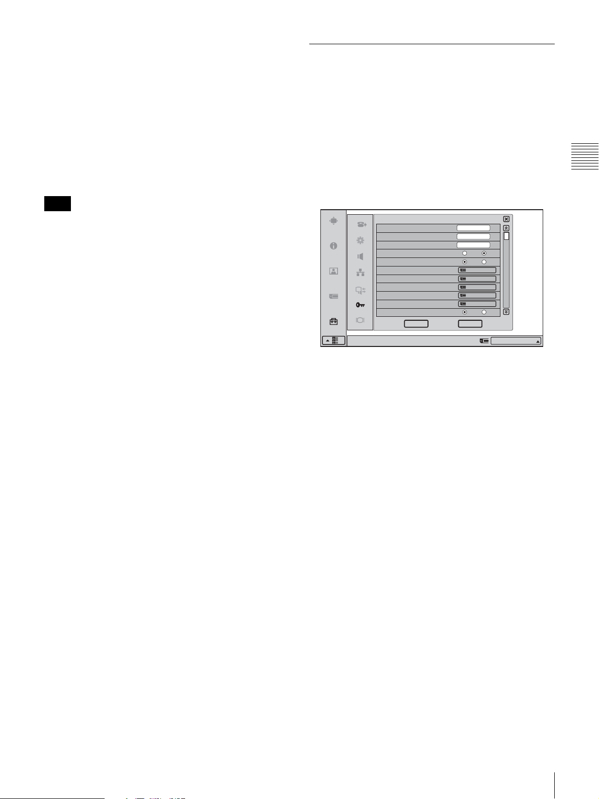
30fps: Receive CIF format video at a maximum rate of 30
frames per second.
Administrator Setup Menu
Audio Mode
Select an audio compression method for reception.
Auto: Match the audio mode selected at the far-end
system.
MPEG4 Audio: Use MPEG4 compliant compression.
G.722: Use G.722 compliant compression.
G.729: Use G.729 compliant compression.
G.728: Use G.728 compliant compression.
G.711: Use G.711 compliant compression.
Note
If the far-end videoconferencing system does not support
the audio compression method selected at the ViewPoint
8050, the G.711 method will automatically be used.
LAN Bandwidth
Select the bandwidth to be used for reception.
Available settings are 64 kbps, 128 kbps, 256 kbps, 384
kbps, 512 kbps, 768 kbps, 1024 kbps, 1536 kbps, 2048
kbps, and “User Input”.
Input LAN Bandwidth
When “User Input” was selected for “LAN Bandwidth”,
enter the bandwidth value here.
Far End Camera Control
Select whether to enable far-end camera control.
On: Normally this setting should be selected, to allow
control of the far-end camera.
Off: Disable control of the far-end camera.
H.239 (Presentation)
Select whether to use the H.239 compliant presentation
function.
On: Enables use of the H.239 compliant presentation
function.
Off: Disables use of the H.239 compliant presentation
function.
The Administrator Setup menu is used for the system
administrators. When you specify an administrator
password in this menu, that password will be required
when making changes in the setup menus (excluding the
Display Setup menu) and Phone Book. Entering the
password is also required to access the Administrator
Setup menu.
Page 1/11
Administrator Setup
Administrator Password
Phone Book Modification Password
Remote Access Passward
Web Monitor
Web Access
Save Phone Book
Load Phone Book
Create Private Phone Book
Delete Private Phone Book
Copy to Private Phone Book
Auto Dialing
Right-click the mouse to display a help message.
Administrator Password
Sets a password up to ten characters long for the system
administrator.
This password will be required when saving
configurations in the setup menus (excluding the Display
Setup menu) and accessing the Administrator Setup menu
and Phone Book.
Phone Book Modification Password
Sets a password up to ten characters long for modifying the
Phone Book.
Remote Access Password
Sets a password up to ten characters long for accessing this
System from a Web browser or telnet. Accessing from a
Web browser is also enabled by entering the administrator
password.
1/11
On Off
On Off
Save
Load
Create
Delete
Copy
On Off
CancelOK
IP:012.345.678.912
Chapter 2
Registration and Setup
Web Monitor
Selects whether to permit the monitoring of a
videoconference (automatic updating of JPEG images)
from a Web browser.
On: Permits the monitoring of a videoconference via a
Web browser.
Off: Prohibits the monitoring of a videoconference via a
Web browser.
Web Access
Selects whether or not to permit accessing the ViewPoint
8050 via a Web browser or Telnet.
On: Permits accessing via a Web browser or Telnet.
Off: Prohibits accessing via a Web browser or Telnet.
Registering Local Information
35
Page 38
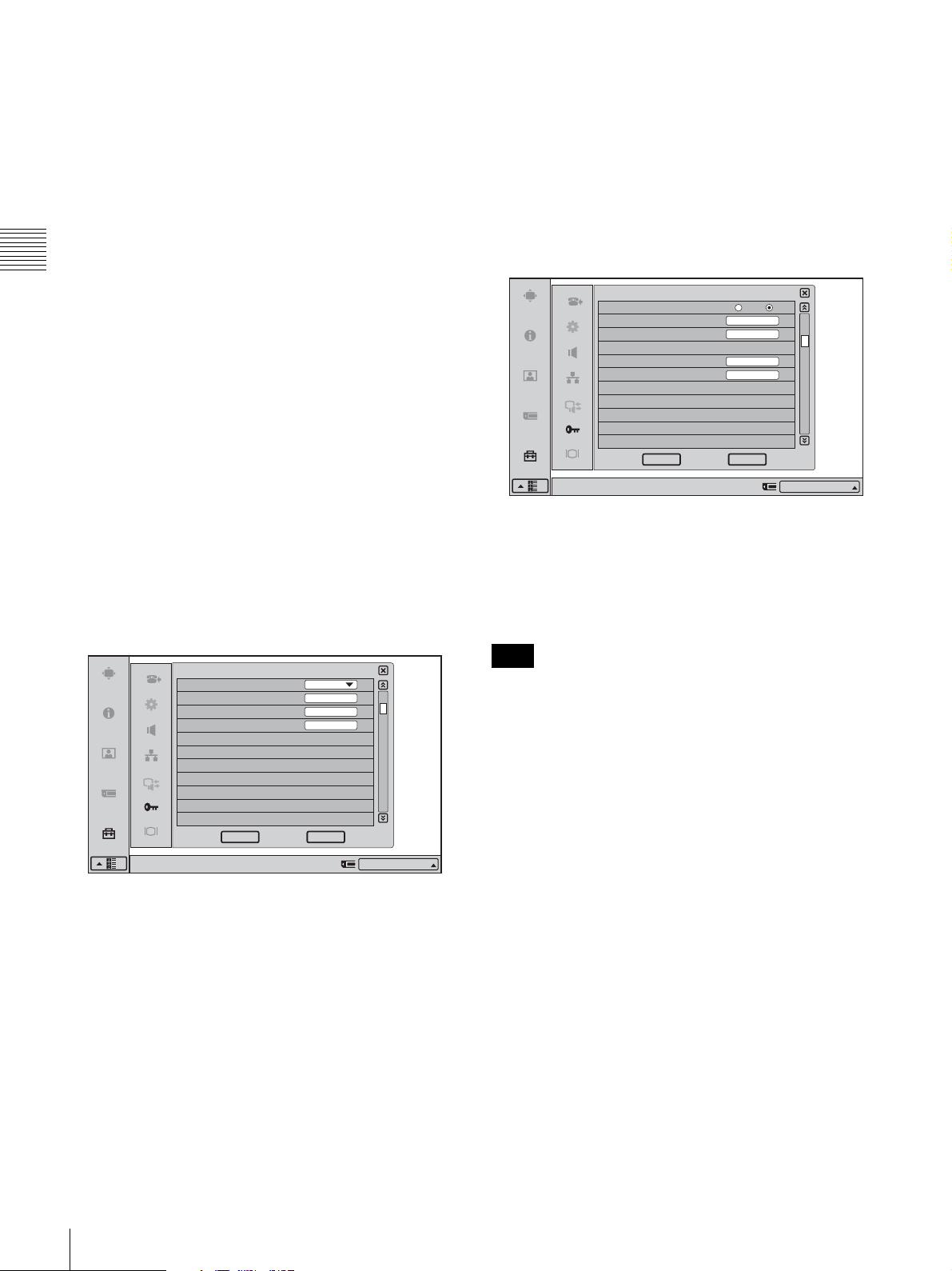
Save Phone Book
Saves the data in the Phone Book in a “Memory Stick”.
The data in the “Memory Stick” will be overwritten.
User Alias
Enter the user name (H.323 alias) to be registered in the
gatekeeper.
Load Phone Book
Loads the data in the Phone Book from a “Memory Stick”.
The data in the Phone Book will be overwritten.
Create Private Phone Book
Selects to create an empty folder and file for a Private
Phone Book in an inserted “Memory Stick”.
Chapter 2
Delete Private Phone Book
Selects to delete the Private Phone Book folder in the
inserted “Memory Stick”.
Registration and Setup
Copy to Private Phone book
Selects to copy all the contents of the Phone Book to a
Private Phone Book in the inserted “Memory Stick”.
Auto Dialing
You can create a Private Phone Book in a “Memory Stick”.
This item is used to select whether or not to automatically
dial the address of a single contact on a specified list in the
Private Phone Book simply by inserting the “Memory
Stick”.
On: Enables automatic dialing.
Off: Disables automatic dialing.
Page 2/11
User Number
Enter the user number (E.164 number) to be registered in
the gatekeeper.
Page 3/11
Administrator Setup
SNMP Mode
Trap Destination
Community
Description
Location
Contact
Right-click the mouse to display a help message.
public
Videoconference Device
SNMP Mode
Selects whether the SNMP (Simple Network Management
Protocol) agent service is enabled or not.
On: Enables the SNMP agent service.
Off: Disables the SNMP agent service.
3/11
On Off
CancelOK
IP:012.345.678.912
Administrator Setup
Gatekeeper Mode Off
Gatekeeper Address
User Alias
User Number
Right-click the mouse to display a help message.
2/11
CancelOK
IP:012.345.678.912
Gatekeeper Mode
Sets whether you use the gatekeeper that controls access to
a remote party.
Using the gatekeeper allows you to dial using the user
name or user number.
Auto: Detects the gatekeeper automatically and uses it.
On: Enables use of the gatekeeper.
Off: Disables use of the gatekeeper.
Gatekeeper Address
Enter the gatekeeper address used when “Gatekeeper
Mode” is set to “On”.
Note
Changes made in the SNMP Mode setting take effect after
restarting.
Trap Destination
Enter the address of the trap destination SNMP manager.
Community
Enter the community name managed by the SNMP
manager. The default setting is “public”. Normally, there
is no need to change.
Description
Enter the description of this system. The default setting is
“Videoconference Device” and cannot be changed.
Location
Enter the location where this system is installed.
Contact
Enter information on the administrator of this system.
36
Registering Local Information
Page 39
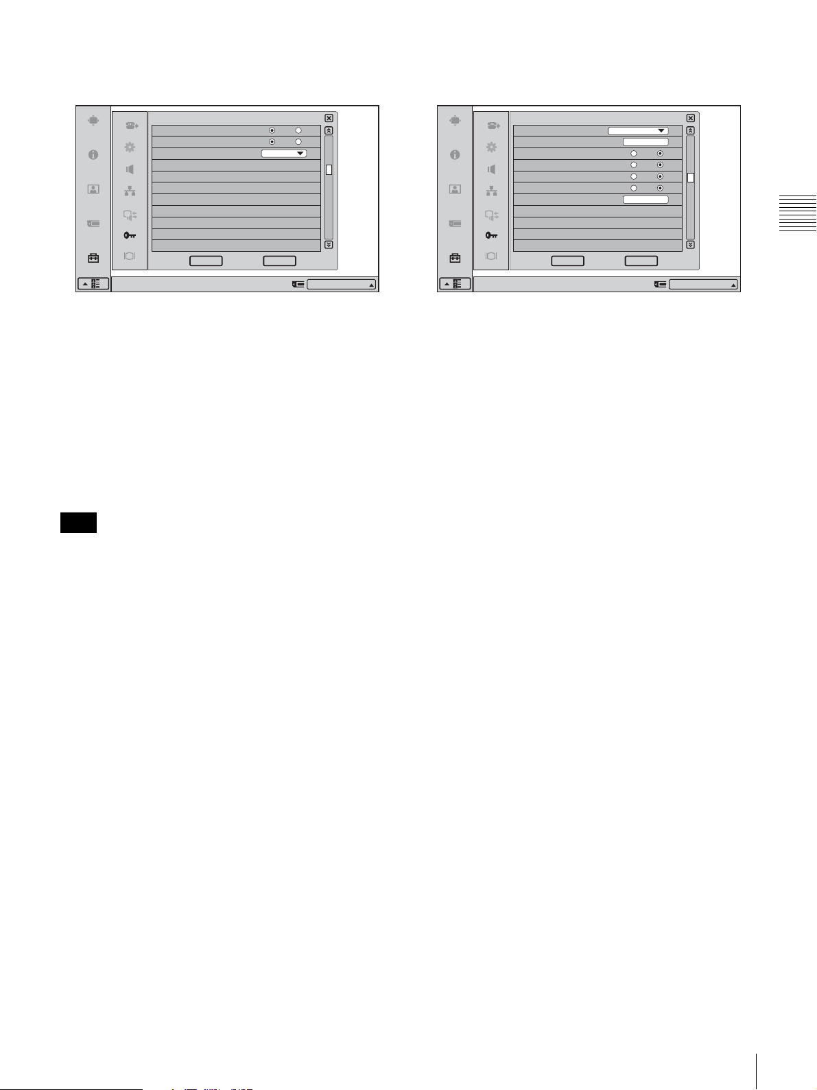
Page 4/11
Page 5-8/11
Administrator Setup
Packet Resend Request
Adaptive Rate Control
LAN Mode
Right-click the mouse to display a help message.
Auto Negotiation
On Off
On
CancelOK
4/11
Off
IP:012.345.678.912
Packet Resend Request
Selects whether or not to request to resend the packet when
a packet loss occurs during communication.
On: Requests resending a packet.
Off: Does not request resending a packet.
Adaptive Rate Control
Sets whether or not to always optimize the LAN
bandwidth.
On: Always optimizes.
Off: Disables optimization of the LAN bandwidth.
Note
This setting is enabled only when “Packet Resend
Request” is set to “Off”. When “Packet Resend Request”
is set to “On”, this item is always set to “On”.
LAN Mode
Selects the interface type and the communication mode of
the LAN connection.
Auto Negotiation: The interface type and the
communication mode are recognized automatically.
100Mbps Full Duplex: Connects via 100BASE-TX in
full duplex mode.
100Mbps Half Duplex: Connects via 100BASE-TX in
half duplex mode.
10Mbps Full Duplex: Connects via 10BASE-T in full
duplex mode.
10Mbps Half Duplex: Connects via 10BASE-T in half
duplex mode.
Administrator Setup
TOS(Video)
IP Precedence
Low Delay
High Throughput
High Reliability
Minimum Cost
Diffserve
Right-click the mouse to display a help message.
Off
5/11
On Off
On Off
On Off
On Off
CancelOK
IP:012.345.678.912
Each page allows you to configure TOS (Type of Service)
Field settings by data type.
Page 5/11: TOS (Video)
Configure TOS (Type of Service) Field settings for video
data.
Page 6/11: TOS (Audio)
Configure TOS (Type of Service) Field settings for audio
data.
Page 7/11: TOS (Presentation)
Configure TOS (Type of Service) Field settings for the
RGB data output from the Dual Stream Box.
Page 8/11: TOS (Camera Control)
Configure TOS (Type of Service) Field settings for camera
control signals.
TOS
Selects how to define the TOS (Type of Service) field for
an IP datagram.
IP Precedence: Defines the TOS field as IP Precedence.
Diffserve: Defines the TOS field as Diffserve.
Off: Does not define the TOS field.
IP Precedence
Enter the IP Precedence value (0 – 7).
Low Delay
Selects whether or not to specify the bit rate of Low Delay
for the TOS field.
On: Specifies the bit rate of Low Delay for the TOS field.
Off: Does not specify the bit rate of Low Delay for the
TOS field.
Chapter 2
Registration and Setup
High Throughput
Selects whether or not to specify the bit rate of High
Throughput for the TOS field.
On: Specifies the bit rate of High Throughput for the TOS
field.
Off: Does not specify the bit rate of High Throughput for
the TOS field.
High Reliability
Selects whether or not to specify the bit rate of High
Reliability for the TOS field.
Registering Local Information
37
Page 40
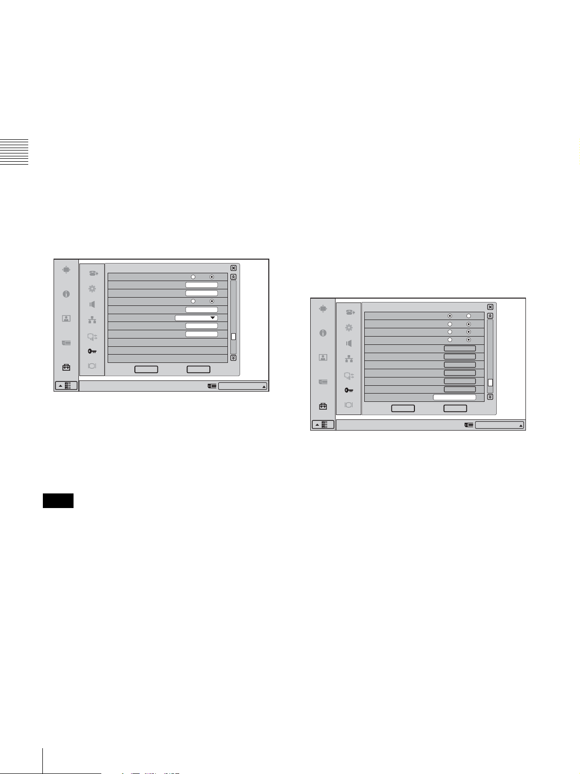
On: Specifies the bit rate of High Reliability for the TOS
field.
Off: Does not specify the bit rate of High Reliability for
the TOS field.
Minimum Cost
Selects whether or not to specify the bit rate of Minimum
Cost for the TOS field.
On: Specifies the bit rate of Minimum Cost for the TOS
field.
Off: Does not specify the bit rate of Minimum Cost for the
Chapter 2
TOS field.
Diffserve
Enter the Diffserve value (0 – 63).
Registration and Setup
Off: Does not use the static IP for a PPPoE connection.
Fixed IP Address for PPPoE
Enter the static IP address when “Fixed IP for PPPoE” is
set to “On”.
PPPoE DNS
Selects whether to obtain the DNS server addresses
automatically or to specify them manually when
connecting to LAN using PPPoE.
Obtain Automatically: Allows you to obtain the DNS
server addresses automatically.
Specify: Specifies the DNS server addresses.
Primary DNS
Enter a primary DNS address.
Page 9/11
Administrator Setup
PPPoE
PPPoE User Name
PPPoE Password
Fixed IP for PPPoE
Fixed IP Address for PPPoE
PPPoE DNS
Primary DNS
Secondary DNS
Right-click the mouse to display a help message.
Obtain Automatically
PPPoE
Selects whether or not to use PPPoE for LAN connection.
You can use the B FLET’S or FLET’S ADSL services
without connecting a router when using PPPoE.
On: Uses PPPoE for LAN connection.
Off: Does not use PPPoE.
Notes
• Operations of PPPoE for LAN connection are presently
verified only for Japanese NTT B FLET’S and FLET’S
ADSL services.
• “FLET’S” is a trademark of NTT East and NTT West
Corporations in Japan.
PPPoE User Name
Enter a user name when you use PPPoE for LAN
connection.
PPPoE Password
Enter a password when you use PPPoE for LAN
connection.
Fixed IP for PPPoE
Selects whether or not to make a PPPoE connection using
the static IP.
On: Uses the static IP for a PPPoE connection.
9/11
On Off
On Off
CancelOK
IP:012.345.678.912
Secondary DNS
Enter a secondary DNS address.
Page 10/11
Administrator Setup
Capture remote image
Ringer with headphones
Display DTMF button
Auto Restore
Restore factory defaults
Save Application Software
Update software
Memory Stick Format
Save Setup
Load Setup
Function Extension Command
Right-click the mouse to display a help message.
Capture remote image
Select whether to automatically capture thumbnail still
images of the remote party when a videoconference has
started.
On: Automatically capture thumbnail images.
Off: Do not automatically capture thumbnail images.
Ringer with headphones
Select whether the ringer on the main unit also rings when
headphones are in use.
On: Enable ringer sound from speaker on main unit also.
The volume of the ringer tone depends on the
headphone ringer level setting.
Off: Disable ringer sound from speaker on main unit.
Display DTMF button
Select whether to display the DTMF button in the
communication screen. Clicking the DTMF button
displays the DTMF soft keyboard.
On: Display the DTMF button.
Off: Do not display the DTMF button.
On Off
On Off
On Off
On Off
Start
Save
Start
Start
Save
Load
CancelOK
10/11
IP:012.345.678.912
38
Registering Local Information
Page 41
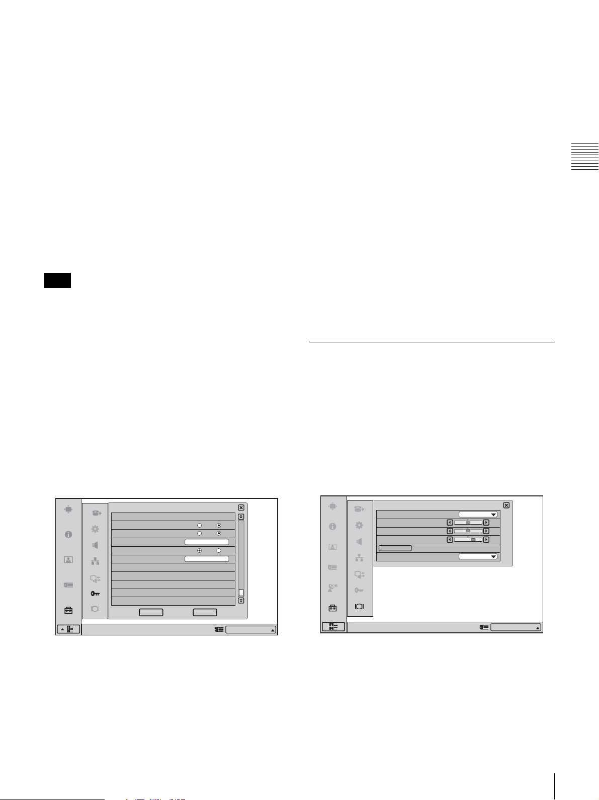
Auto Restore
Select whether to turn the system on automatically after
recovering from a power outage.
On: Automatically turns the system on when power is
restored.
Off: Does not automatically turn the system on when
power is restored.
SPB Mode
Selects whether to use the server managing the Shared
Phone Book.
On: Enables use of the server managing the Shared Phone
Book.
Off: Disables use of the server managing the Shared Phone
Book.
Restore factory defaults
Restores the system to the factory default settings.
All settings revert to defaults and Phone Book data is
deleted.
Save Application Software
Saves application software to a “Memory Stick”.
Update software
Performs a software update or rollback using a “Memory
Stick.”
Note
When performing a rollback, you can revert as far back as
the factory-installed version.
Memory Stick Format
Formats a “Memory Stick”.
Save Setup
Saves the settings information to a “Memory Stick”.
Load Setup
Loads settings information from a “Memory Stick”.
Function Extension Command
This function is not supported.
SPB Server Address
Enter the IP address for the server managing the Shared
Phone Book.
SPB Auto Registration
Selects whether information about terminals is registered
automatically on the server managing the Shared Phone
Book.
On: Enables automatic registration on the server
managing the Shared Phone Book.
Off: Disables automatic registration on the server
managing the Shared Phone Book.
SPB Server Password
Enter the password for the server managing the Shared
Phone Book.
Display Setup Menu
Lets you make display related settings. Settings are made
separately for videoconference mode and PC (computer
display) mode.
For details on how to make the settings, see “Adjusting the
Picture Quality on the Display” on page 84.
Chapter 2
Registration and Setup
Page 11/11
On Off
On Off
On Off
CancelOK
11/11
IP:012.345.678.912
Administrator Setup
Shared Phone Book Setup
Shared Phone Book
SPB Mode
SPB Server Address
SPB Auto Registration
SPB Server Password
Right-click the mouse to display a help message.
0.0.0.0
Shared Phone Book
Allows you to select whether to use the Shared Phone
Book located on the server.
On: Enables use of the Shared Phone Book.
Off: Disables use of the Shared Phone Book.
Videoconference Page 1/1
Display Setup (Videoconference)
Quality Mode
Picture
Brightness
Backlight
Reset
Wide Mode
Right-click the mouse to display a help message.
Quality Mode
Selects the color tone of the image.
Vivid: Slightly bluish color tone.
Standard: Setting between Vivid and Pro.
Pro: Slightly reddish color tone.
Standard
Zoom
50
50
70
IP:012.345.678.912
Registering Local Information
39
Page 42
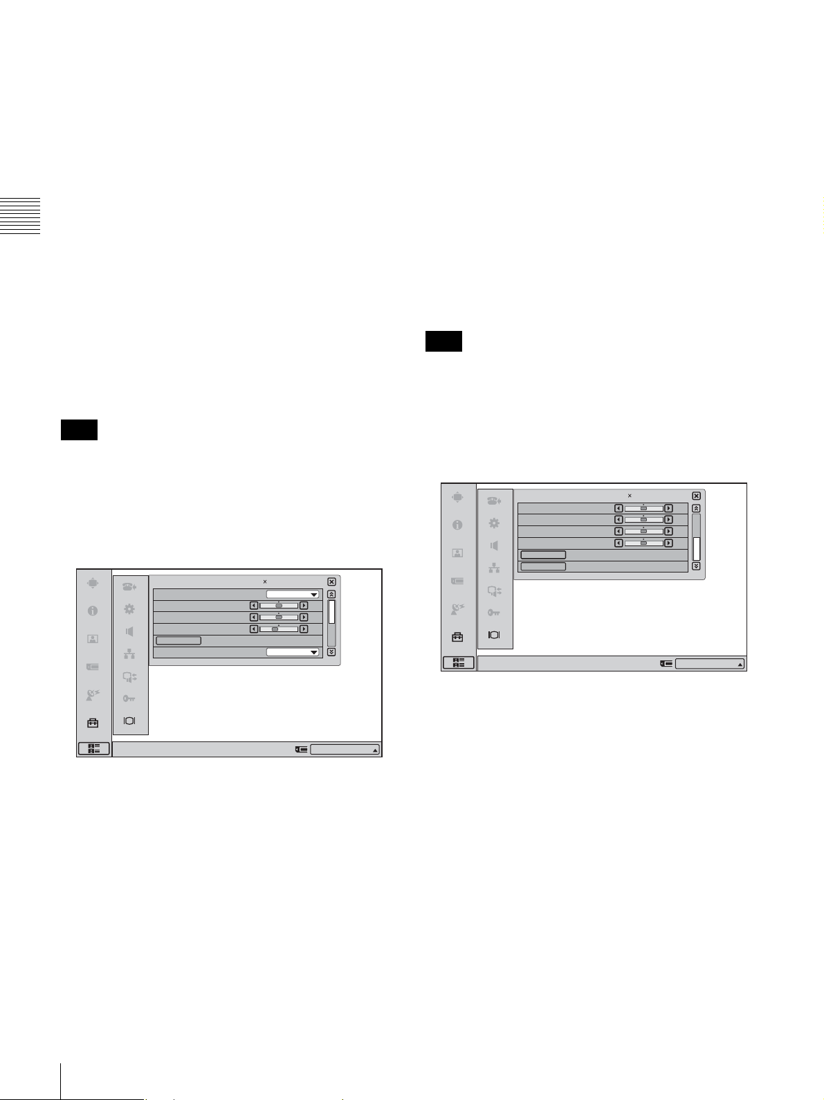
Picture
Adjusts the picture contrast.
The contrast increases as the value gets larger.
Backlight
Adjusts the brightness of the backlight.
The backlight gets brighter as the value gets larger.
Brightness
Adjusts the picture brightness.
The brightness increases as the value gets larger.
Backlight
Adjusts the brightness of the backlight.
The backlight gets brighter as the value gets larger.
Chapter 2
Reset
Resets the settings to the default condition.
Registration and Setup
Wide Mode
Switches the display mode.
Normal: Shows the 4:3 image as is.
Wide: Stretches the 4:3 image horizontally to fit the wide
screen.
Zoom: Enlarges the 4:3 image and then crops the top and
bottom to fit the wide screen.
Note
When Picture-and-Picture or Side-by-Side is selected for
the screen layout, the display does not change, even when
Wide Mode is adjusted.
PC Page 1/2
Display Setup (PC)
Quality Mode
Picture
Brightness
Backlight
Reset
Wide Mode
1280 768/60Hz
Middle
Normal
1/2
50
50
40
Reset
Resets the settings to the default condition.
Wide Mode
Switches the display mode.
When a WXGA 1280
× 768 image is input, it is displayed
in wide mode regardless of the display mode setting.
Normal: Shows the 4:3 image as is.
Wide: Stretches the 4:3 image horizontally to fit the wide
screen.
Zoom: Enlarges the 4:3 image and then crops the top and
bottom to fit the wide screen.
Note
When Picture-and-Picture or Side-by-Side is selected for
the screen layout, the display does not change, even when
Wide Mode is adjusted.
PC Page 2/2
H Shift
1280 768/60Hz
V Shift
Phase
Pitch
Auto Adjust
Reset
Right-click the mouse to display a help message.
2/2Display Setup (PC)
50
50
50
50
IP:012.345.678.912
Right-click the mouse to display a help message.
Quality Mode
Selects the color temperature of the image.
Low: Sets the color temperature to Low.
Middle: Sets the color temperature to Middle.
High: Sets the color temperature to High.
Picture
Adjusts the picture contrast.
The contrast increases as the value gets larger.
Brightness
Adjusts the picture brightness.
The brightness increases as the value gets larger.
40
Registering Local Information
IP:012.345.678.912
H Shift
Use this item to shift the entire screen horizontally.
Moves the screen left and right.
V Shift
Use this item to shift the entire screen vertically.
Moves the screen up and down.
Phase
Use this item to minimize character blurring and lateral
fringes.
Pitch
Use this item to remove large longitudinal fringes.
Auto Adjust
Automatically adjusts the phase and pitch.
Reset
Resets the settings to the default condition.
Page 43
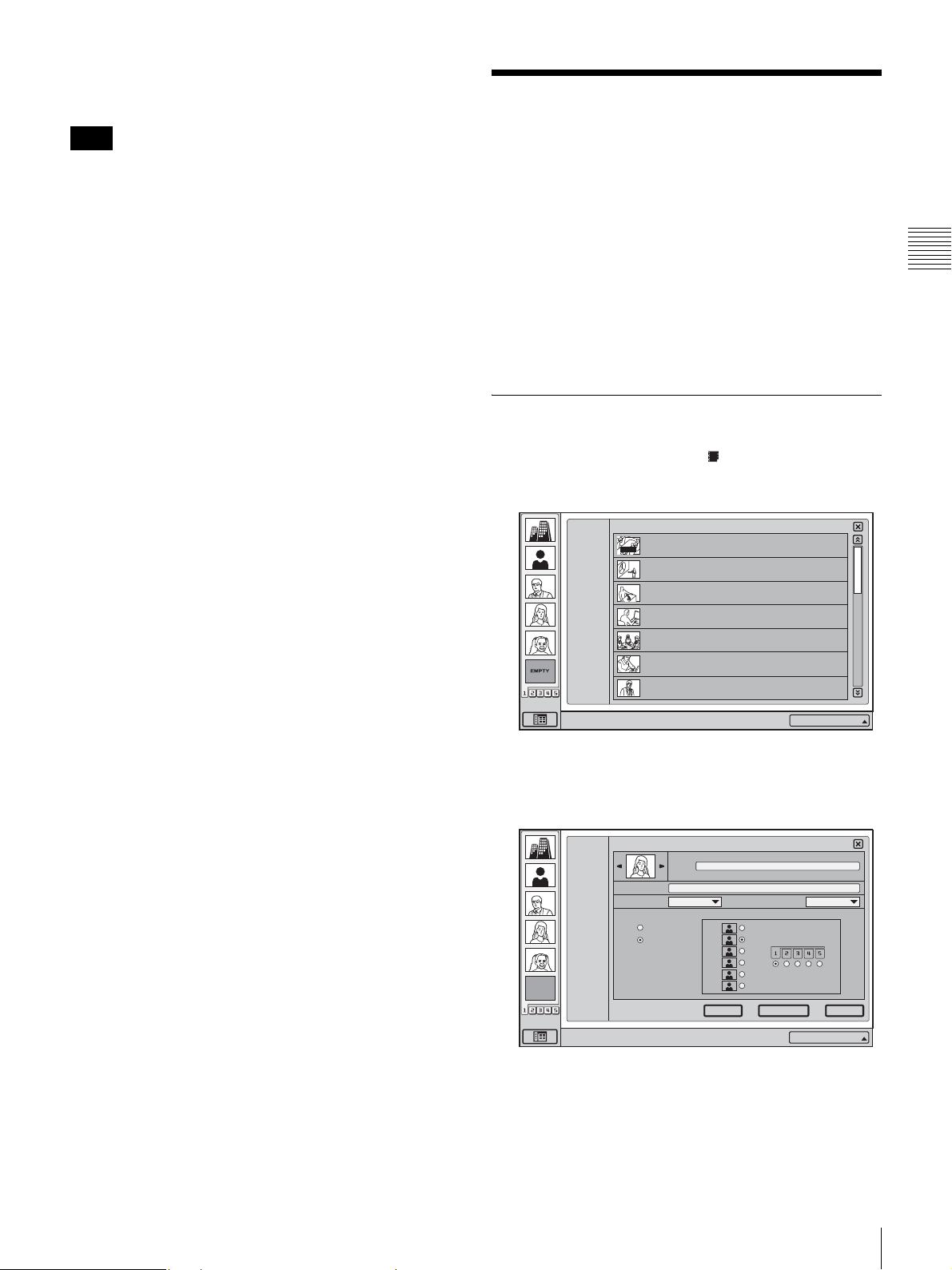
Screen Resolution/Refresh Rate
Displays the screen resolution and refresh rate.
Registering a Remote
Note
The adjustment range of the H Shift and V Shift may differ
depending on the specifications of the RGB signal input.
Party in the Phone Book
You can register the IP address and other information for a
remote party in the Phone Book, allowing you to dial the
party very easily.
Up to 500 remote parties can be registered in the Phone
Book. You can also store a still image such as a
participant’s portrait in the index list.
In addition to the regular Phone Book of the
Videoconferencing Terminal, you can create a Private
Phone Book on a “Memory Stick”.
Registering a New Remote Party
1
In the launcher menu, click (Phone Book).
The Phone Book menu opens.
ALL
A--I
J--S
T-- Z
0--9
New
Phone Book
AUTO
HQ4Room5
05032105678
Takanawa
0657896709
HQ5Room6
XXXXXXXXXX
HQ5Room6
XXXXXXXXXX
HQ5Room6
XXXXXXXXXX
HQ5Room6
XXXXXXXXXX
HQ5Room6
XXXXXXXXXX
1/3
Chapter 2
Registration and Setup
2
Click “New”.
Right-click the mouse to display a help message.
IP:012.345.678.912
The List Edit menu appears.
ALL
List Edit
A
-
I
-
S
J
Phone Book
-
Z
T
Line I/F
-
9
0
One Touch Dial
New
EMPTY
Right-click the mouse to display a help message.
3
Enter the name of a remote party in the Index text box.
Index
IP 1024
Off
On
Duplicate Save
LAN Bandwidth
IP:012.345.678.912
For information on character input, see “Entering
Characters” on page 28.
1/3
Cancel
Registering a Remote Party in the Phone Book
41
Page 44
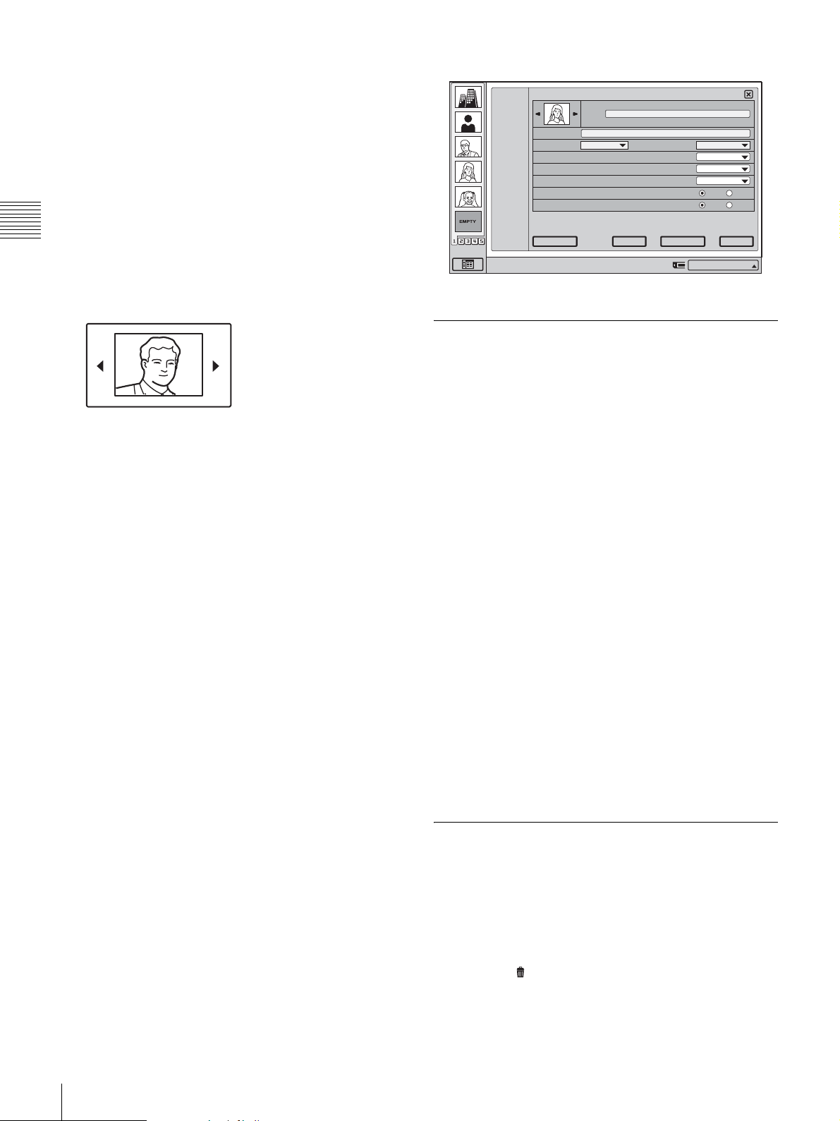
4
Enter the IP address of the remote party in the IP
address text box.
5
Select the line interface you are using to connect to a
remote party with “Line I/F”.
IP: Connect to a videoconferencing system on the
remote site via a LAN.
6
Set the LAN bandwidth to use.
ALL
J
T
New
-
I
A
-
S
-
Z
-
9
0
List Edit
Index
Address
Line I/F
Video Mode
Video Frame
Audio Mode
Far End Camera Control
H.239(Presentation)
IP 1024
LAN Bandwidth
Auto
15fps
Auto
On Off
On Off
Chapter 2
7
Select the thumbnail image to be shown in the Phone
Book. You can select the line interface icon or a still
image automatically captured during a
Registration and Setup
videoconference.
Click b/B to select the image.
When a “Memory Stick” is inserted into the unit, you
can also select still images stored on the “Memory
Stick.”
For details on the automatic capturing of still images,
see “Saving Remote Party Pictures Automatically –
Automatic Image Capture Feature” on page 72.
8
Specify whether to include the entry in the One Touch
Dial list. To do this, select the group and the position
within the group.
9
Click “Save”.
The settings are registered in the Phone Book.
To configure different dial settings for each entry
When you set “More Options Enable” to “On” in the Dial
settings of the Communication Mode menu, “More
Options” appears in the List Edit menu. Clicking this
allows you to configure Video Mode, Video Frame, Audio
Mode, Far End Camera Control, and H.239 (Presentation)
settings for each entry individually. Click “Back” to return
to the standard List Edit menu.
Back
Right-click the mouse to display a help message.
Duplicate Save
Cancel
IP:012.345.678.912
Changing the Contents of the Phone Book
You can change the IP address, name, or other setting
registered in the Phone Book.
1
Open the Phone Book menu.
2
Move the mouse cursor to the entry you want to
change, and click “Edit”.
The List Edit menu appears.
3
Change the IP address, name, or other setting.
4
Click “Save”.
The corrected entry is saved.
To configure different dial settings for each entry
When you set “More Options Enable” to “On” in the Dial
settings of the Communication Mode menu, you can
configure Video Mode, Video Frame, Audio Mode, Far
End Camera Control, and H.239 (Presentation) settings for
each entry individually using the List Edit menu.
For details, see “Registering a New Remote Party” on
page 41.
Deleting a Registered Remote Party
42
Registering a Remote Party in the Phone Book
Follow the procedure below to delete a remote party from
the Phone Book.
1
Open the Phone Book menu.
2
Move the mouse cursor to the entry you want to delete,
and click .
The message “Delete Entry?” appears.
Page 45
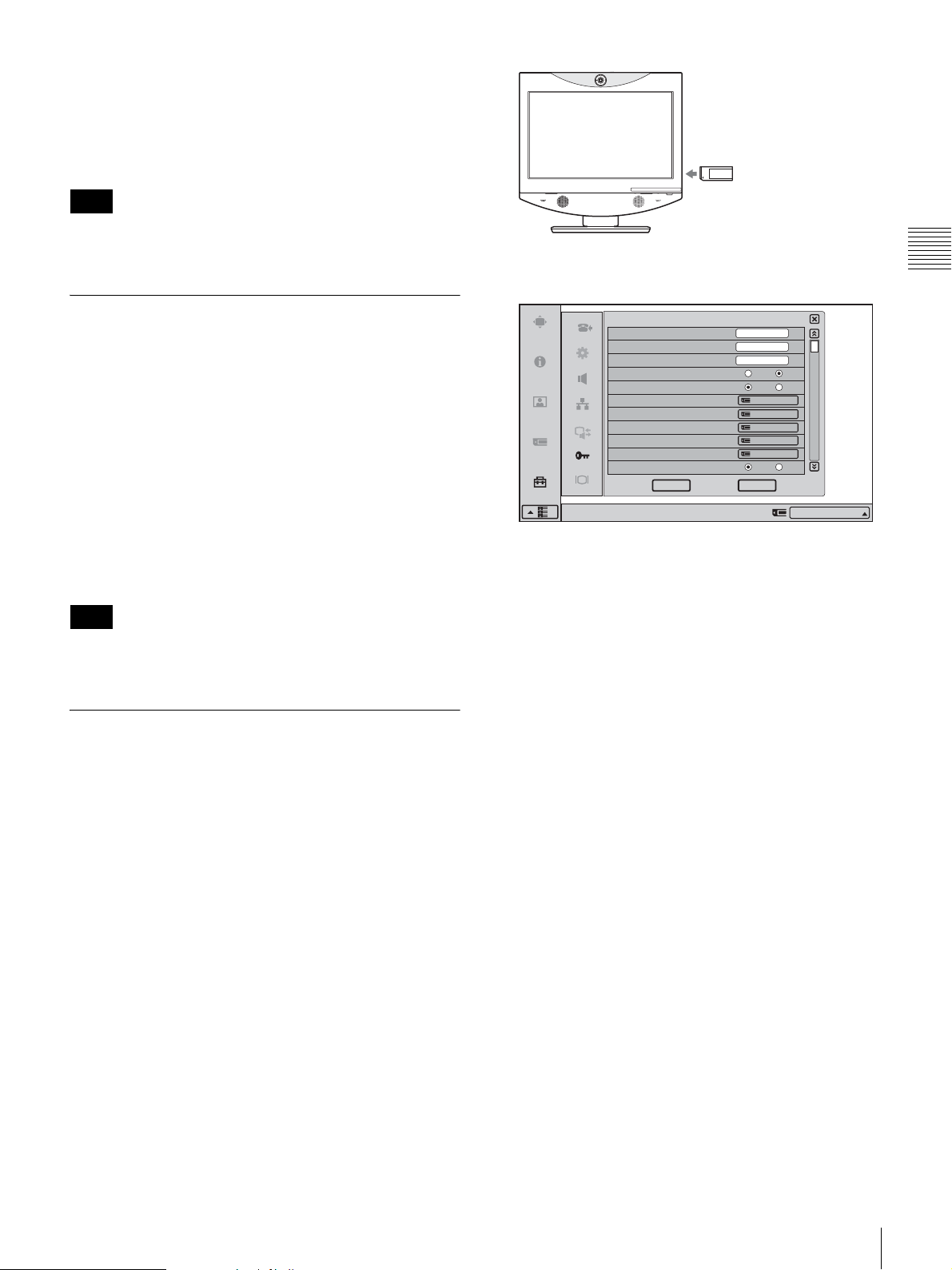
3
Click “OK”.
The selected party is deleted.
To cancel deleting
Click “Cancel” in step 3.
Note
If the deleted party has been registered for One Touch
Dial, the One Touch Dial entry will also be deleted.
2
Open Page 1 of the Administrator Setup menu.
Chapter 2
Copying an Entry in the Phone Book
1
Open the Phone Book menu.
2
Move the mouse cursor to the entry you want to copy,
and click “Edit”.
The List Edit menu appears.
3
Click “Duplicate”.
The data for the selected entry are copied, and the file
name is followed by “-1, -2, -3”. You can use the data
for another entry after modifying only the necessary
items.
Note
Even if the copied entry was registered in the One Touch
Dial, this information is not copied.
Creating a Private Phone Book
You can create your own Phone Book (Private Phone
Book) in a “Memory Stick”. Once the Private Phone Book
is registered, inserting the “Memory Stick” into the system
changes the Phone Book menu to the Private Phone Book
menu. You can also activate the Auto Dial feature,
allowing you to start dialing automatically to one of the
lists simply by inserting the “Memory Stick”.
To register a new remote party in a Private
Phone Book
1
Insert a “Memory Stick” in which you want to register
a remote party into the Memory Stick slot of the
system.
Insert the “Memory Stick” with the front facing you
and in the direction of the arrow on the top.
Administrator Setup
Administrator Password
Phone Book Modification Password
Remote Access Passward
Web Monitor
Web Access
Save Phone Book
Load Phone Book
Create Private Phone Book
Delete Private Phone Book
Copy to Private Phone Book
Auto Dialing
Right-click the mouse to display a help message.
1/11
On Off
On Off
Save
Load
Create
Delete
Copy
On Off
CancelOK
IP:012.345.678.912
For details on how to open the menu, see “Opening the
Setup Menu” on page 29.
3
Select “Create Private Phone Book”.
The message “Create a Private Phone Book?” appears.
4
Click “OK”.
An empty Private Phone Book is created in the
“Memory Stick”.
5
Register a new remote party.
The procedure is the same as that for registering in the
Phone Book. Proceed with steps 2 to 7 in “Registering
a New Remote Party” on page 41.
The procedures for how to change the contents of the
Private Phone Book, how to delete the registered remote
party, or how to copy the setting of the Private Phone Book
are the same as those for the Phone Book. Open the Private
Phone Book menu and proceed with the steps described on
page 42.
To copy all the contents of the Phone Book
to the Private Phone Book
Insert the “Memory Stick” in which you want to store the
Private Phone Book into the Memory Stick slot on the
system, then select “Copy to Private Phone Book” from
Page 1 of the Administrator Setup menu. All the data
Registration and Setup
Registering a Remote Party in the Phone Book
43
Page 46
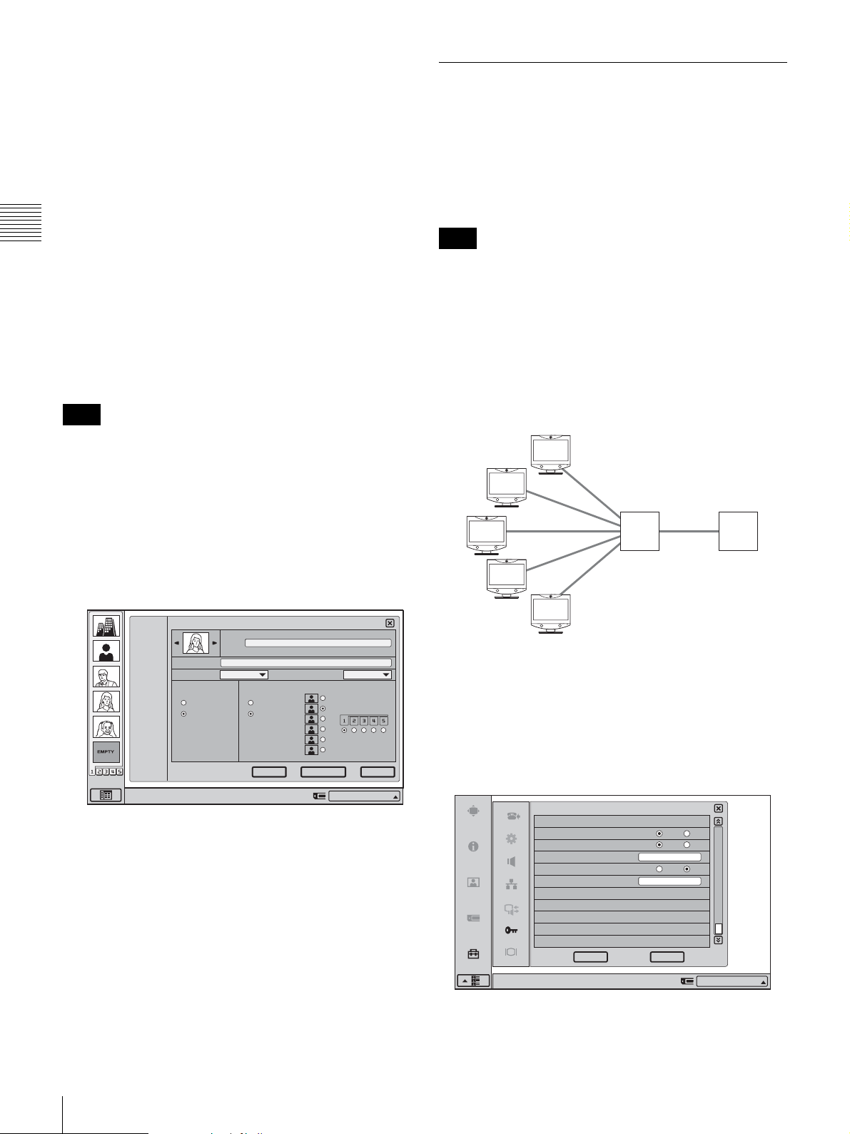
registered in the Phone Book are copied to the inserted
“Memory Stick”.
To delete the Private Phone Book from the
“Memory Stick”
Insert the “Memory Stick” from which you want to delete
the registered Private Phone Book into the Memory Stick
slot on the system, then select “Delete Private Phone
Book” from Page 1 of the Administrator Setup menu. All
the data are deleted from the inserted “Memory Stick”.
Chapter 2
To dial a specified entry of the Private
Registration and Setup
Phone Book automatically
If you set “Auto Dialing” in the Administrator Setup menu
to “On”, you can automatically dial one of the entries in the
Private Phone Book simply by inserting the “Memory
Stick” on which the Private Phone Book is stored.
Note
Only one entry can be set for auto dial. The most recent
address for which “Auto Dialing” was set to “On” will be
used.
1
Open the Private Phone Book.
Using the Shared Phone Book
Using the Shared Phone Book function, a phone book
located on a server can be accessed by multiple
Videoconferencing Terminal units.
For details about settings, consult your network
administrator.
Note
You cannot register, edit, delete, or attach images to parties
in the Shared Phone Book. In addition, you cannot copy
parties registered in the Shared Phone Book to the Private
Phone Book.
System configuration example
In this system configuration, sharing of a Phone Book
using H.350 is enabled.
H.350/LDAP
2
Move the mouse cursor to the remote party that you
want to dial automatically, and click the “Edit”.
The List Edit menu appears.
ALL
List Edit
-
I
A
-
S
J
Phone Book
-
Z
T
Line I/F
-
9
0
Auto Dial One Touch Dial
New
Right-click the mouse to display a help message.
3
Set “Auto Dial” to “On” by clicking on the setting.
4
Click “Save”.
Index
IP 1024
Off
On
Off
On
Duplicate Save
LAN Bandwidth
1/3
Cancel
IP:012.345.678.912
The setting is saved and “AUTO” appears on the
Private Phone Book menu list.
To exit from the Private Phone Book menu
Remove the “Memory Stick” in which the Private Phone
Book is registered from the Videoconferencing terminal.
The screen returns to the Phone Book menu.
Server with
Shared Phone
Book
Directory
server
To use the Shared Phone Book
Set “Shared Phone Book” and “SPB Mode” to “On” under
Page 11/11 of the Administrator Setup menu, and enter the
appropriate values for “SPB Server Address” and “SPB
Server Password”.
On Off
On Off
On Off
CancelOK
11/11
IP:012.345.678.912
Administrator Setup
Shared Phone Book Setup
Shared Phone Book
SPB Mode
SPB Server Address
SPB Auto Registration
SPB Server Password
Right-click the mouse to display a help message.
192.100.10.10
abcdefgh
44
Registering a Remote Party in the Phone Book
Page 47
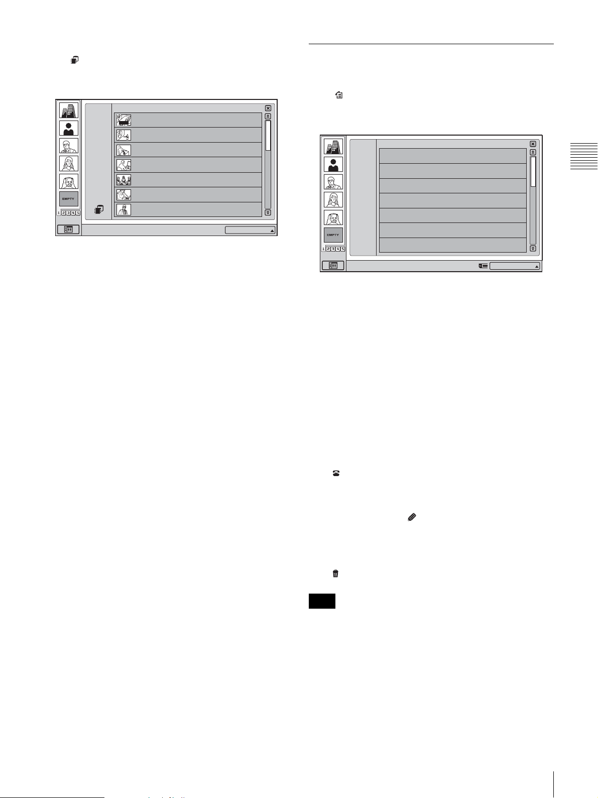
To display the Shared Phone Book
Click at the bottom left of the Phone Book screen to
switch the display to the Shared Phone Book.
Phone Book
ALL
A--I
J--S
T-- Z
0--9
New
Right-click the mouse to display a help message.
AUTO
HQ4Room5
05032105678
Takanawa
0657896709
HQ5Room6
XXXXXXXXXX
HQ5Room6
XXXXXXXXXX
HQ5Room6
XXXXXXXXXX
HQ5Room6
XXXXXXXXXX
HQ5Room6
XXXXXXXXXX
1/3
IP:012.345.678.912
To switch back to the Phone Book or Private Phone Book
from the Shared Phone Book, perform this operation again.
Checking the History of Outgoing and Incoming Calls
Click on the launcher menu to bring up the History
menu.
History
ALL
OUT
IN
Right-click the mouse to display a help message.
IN
OUT
OUT
IN
OUT
IN
IN
2005.07.30 10:10
05032105678
2005.07.30 10:10
0657896709
2005.07.30 10:10
XXXXXXXXXX
2005.07.30 10:10
XXXXXXXXXX
2005.07.30 10:10
XXXXXXXXXX
2005.07.30 10:10
XXXXXXXXXX
2005.07.30 10:10
XXXXXXXXXX
1/3
IP:012.345.678.912
Chapter 2
Registration and Setup
The procedure for dialing registered parties from the
Shared Phone Book is the same as that for the Phone Book.
For details on dialing, see “Calling a Remote Party
Registered in the Phone Book” on page 57.
The History menu shows a list of remote parties to which
the system was recently connected.
When “ALL” is selected, all outgoing and incoming calls
are shown in chronological order. To display only
outgoing or incoming calls, select “OUT” or “IN”.
When the list has several pages, a scroll bar will appear at
the right side of the screen. To advance to the next page,
click the Page button at the bottom of the scroll bar. To go
back to the previous page, click the Page button at the top
of the scroll bar.
You can also scroll through pages by moving the scroll bar
with the mouse.
To dial a history entry
Move the mouse cursor to the entry you want to dial, and
click .
To store a history entry in the Phone Book
Move the mouse cursor to the entry you want to add to the
Phone Book, and click (Save). For details, see
“Changing the Contents of the Phone Book” on page 42.
To delete a history entry
Move the mouse cursor to the entry you want to delete, and
click .
Note
Starting with the newest entry, up to 40 outgoing or
incoming calls are displayed in the history.
Registering a Remote Party in the Phone Book
45
Page 48

Registering a Remote Party for One Touch Dial
You can register remote parties in the One Touch Dial list
in the launcher menu, allowing you to dial them easily at
any time.
Up to 30 remote parties from the Phone Book can be
Chapter 2
registered for One Touch Dial.
Registration and Setup
One Touch Dial Registration
To delete a One Touch Dial registration
from the launcher menu
On the launcher menu, move the mouse cursor to the entry
that you want to delete, and then click .
The launcher menu appears again, and the deleted One
Touch Dial entry is grayed out.
Note
Deleting the One Touch Dial entry in this way will not
delete the Phone Book entry.
Registering the Private One Touch
To register a party in the One Touch Dial, you use the List
Edit menu of the Phone Book.
For information on the steps for One Touch Dial
registration, see the section “Registering a New Remote
Party” on page 41.
To change a One Touch Dial registration
from the Phone Book
If you change the contents of the Phone Book, the contents
of the One Touch Dial registration also change
accordingly.
For information on editing the Phone Book, see “Changing
the Contents of the Phone Book” on page 42.
To delete a One Touch Dial registration
from the Phone Book
Using the List Edit menu of the Phone Book, you can
delete a One Touch Dial registration.
For information on the steps for One Touch Dial deletion,
see the section “Registering a New Remote Party” on page
41.
Dial
You can register the remote parties stored in the Private
Phone Book in a “Memory Stick” for your own One Touch
Dial list.
Once the Private One Touch Dial list is registered,
inserting the “Memory Stick” into the system changes the
One Touch Dial list in the launcher menu to the Private
One Touch Dial list.
The procedures of the registration, deleting and editing of
One Touch Dial are the same as those for the Phone Book
of the system.
Up to 30 remote parties can be registered for your Private
One Touch Dial list.
To change a One Touch Dial registration
from the launcher menu
1
On the launcher menu, move the mouse cursor to the
entry that you want to edit, and then click (Edit).
The List Edit menu opens.
2
Change the registration contents using the List Edit
menu, and click “Save”.
The launcher menu appears again.
The launcher menu One Touch Dial contents and the
Phone Book registration contents are changed at the
same time.
46
Registering a Remote Party for One Touch Dial
Page 49
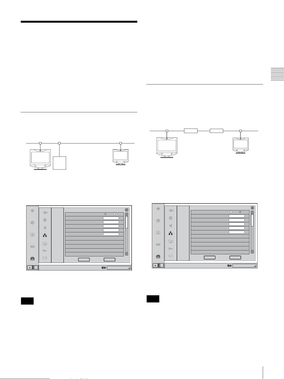
Setting Up the Network Configurations
This section describes how to set up the network
configurations for use with various networks.
For details on the Network Setup menu, see “Network
Setup Menu” on page 32.
To conduct a video conference
Select “IP” for the line interface, enter the remote party’s
IP address in the text box, and dial.
You can set “IP” as the default line interface selection for
the launcher menu by setting “Line I/F” to “IP” in the Dial
settings of the Communication Mode menu.
For details on the setting, see “Communication Mode
Menu” on page 33.
Chapter 2
For details on configurations, consult with the system
administrator.
LAN (Connecting via DHCP)
Configuration example
LAN1 LAN2
DHCP Server 1
Set the “DHCP Mode” to “Auto” under Page 1/3 of the
LAN Setup menu.
LAN
LAN
DHCP Mode
Host Name
IP Address
Network Mask
Gateway Address
DNS Address
1/3
Auto
Off
LAN (Connecting Through a Router)
Configuration example
LAN1
192.100.10.1
192.100.10.10
Enter a name in “Host Name” under Page 1/3 of the LAN
Setup menu, set the “DHCP Mode” to “Off“, and enter the
appropriate values for “IP Address”, “Network Mask”, and
“Gateway Address”.
Virtual Private
Network (VPN)
Router Router
LAN
LAN
DHCP Mode
Host Name
IP Address
Network Mask
Gateway Address
DNS Address
LAN2
192.100.20.1
192.100.20.20
1/3
Auto
Off
VCT1
192.100.10.10
255.255.255.0
192.100.10.1
Registration and Setup
CancelOK
Right-click the mouse to display a help message.
IP:012.345.678.912
The setting has been configured properly if the IP address
appears in the launcher menu.
Note
The information that appears in the launcher menu may
differ depending on the “Number Display” setting in the
Device Setup menu. You can also click the Number
Display portion and select the information to display from
a list.
CancelOK
Right-click the mouse to display a help message.
IP:192.100.10.10
The setting has been configured properly if the correct IP
address appears in the launcher menu.
Note
The information that appears in the launcher menu may
differ depending on the “Number Display” setting in the
Device Setup menu. You can also click the Number
Display portion and select the information to display from
a list.
Setting Up the Network Configurations
47
Page 50
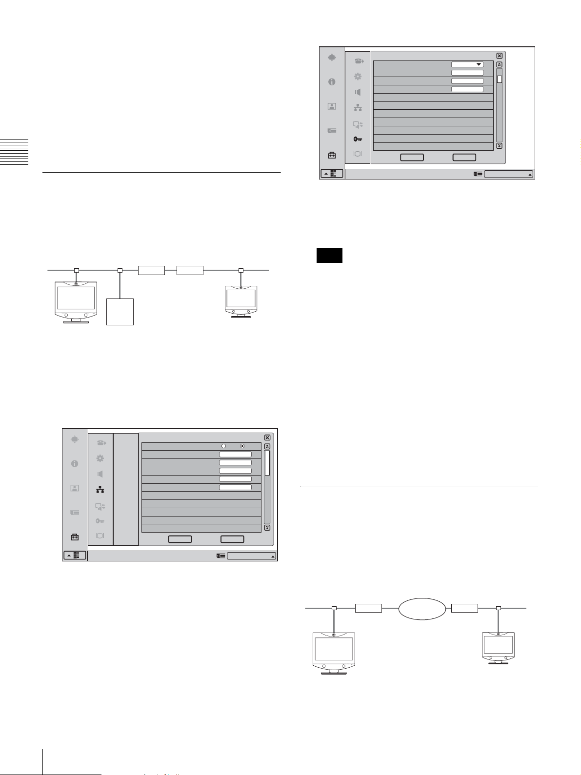
To conduct a video conference
Select “IP” for the line interface, enter the remote party’s
IP address in the text box, and dial.
You can set “IP” as the default line interface selection for
the launcher menu by setting “Line I/F” to “IP” in the Dial
settings of the Communication Mode menu.
For details on the setting, see “Communication Mode
Menu” on page 33.
Chapter 2
LAN (Connecting Through a Gatekeeper)
Registration and Setup
Configuration example
Administrator Setup
Gatekeeper Mode On
Gatekeeper Address
User Alias
User Number
Right-click the mouse to display a help message.
192.100.10.20
VP-A
100
2/11
CancelOK
IP:192.100.10.10
The setting has been configured properly if the correct
IP address appears in the launcher menu and
“Registration Confirmed” appears under
“Gatekeeper” in Page 3/4 of the Status & Info menu.
LAN1
192.100.10.1
Router
Gatekeeper
192.100.10.20
192.100.10.10
User alias: VP-A
User number: 100
1
Enter a name in “Host Name” under Page 1/3 of the
Router
192.100.20.1
192.100.20.20
User alias: VP-B
User number: 200
LAN Setup menu, set the “DHCP Mode” to “Off“, and
enter the appropriate values for “IP Address”,
“Network Mask”, and “Gateway Address”.
LAN
LAN
DHCP Mode
Host Name
IP Address
Network Mask
Gateway Address
DNS Address
Right-click the mouse to display a help message.
Auto
VCT1
192.100.10.10
255.255.255.0
192.100.10.1
CancelOK
IP:192.100.10.10
LAN2
1/3
Off
Note
The information that appears in the launcher menu
may differ depending on the “Number Display” setting
in the Device Setup menu. You can also click the
Number Display portion and select the information to
display from a list.
To conduct a video conference
Select “IP” for the line interface, enter the user alias or user
number set by the remote party in the number entry text
box, and dial.
You can set “IP” as the default line interface selection for
the launcher menu by setting “Line I/F” to “IP” in the Dial
settings of the Communication Mode menu.
For details on the setting, see “Communication Mode
Menu” on page 33.
LAN (Connecting Through NAT)
Connection using NAT allows one IP address to be shared
by several computers on the same LAN. This section
describes how to set up videoconferences conducted in
NAT and global IP environments.
2
Set “Gatekeeper Mode” to “On” under Page 2/11 of
the Administrator Setup menu, and enter the
appropriate values for “Gatekeeper Address”, “User
Alias”, and “User Number”.
48
Setting Up the Network Configurations
Configuration example
192.168.10.1 210.20.20.1
Router
Internet
192.168.10.10
Router
210.20.20.2
(Global address)
Page 51
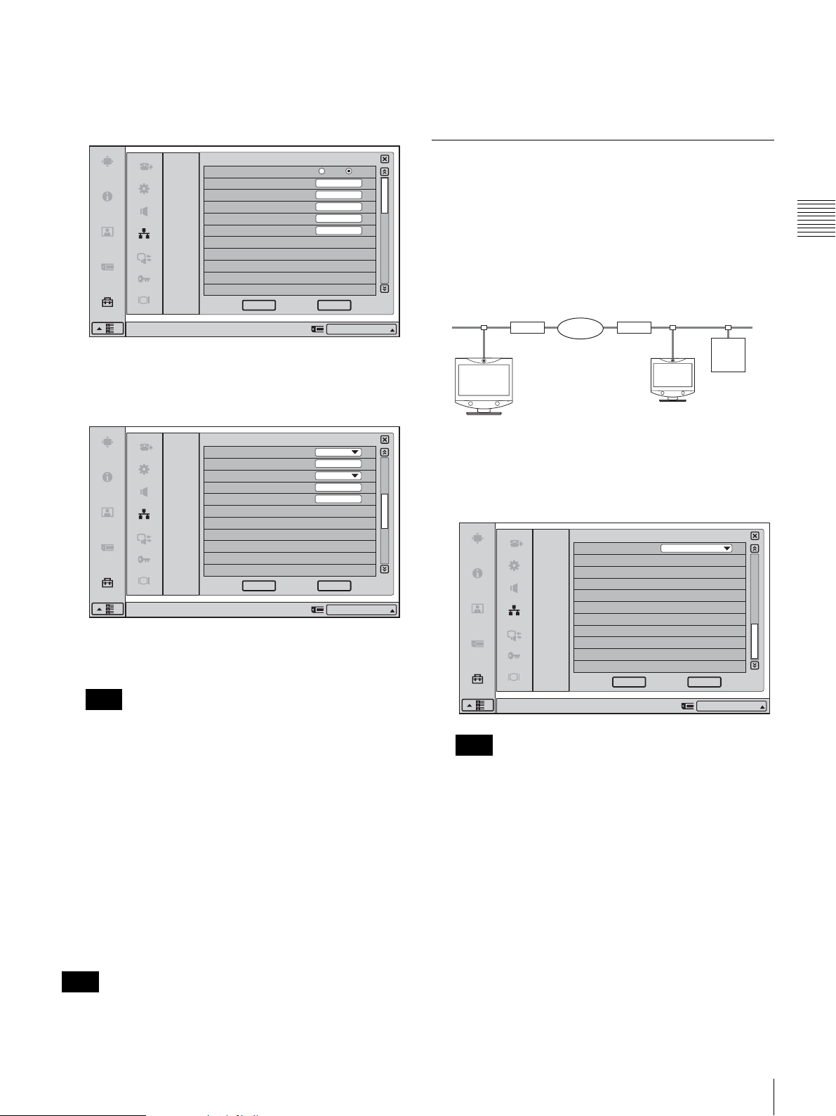
1
Enter a name in “Host Name” under Page 1/3 of the
LAN Setup menu, set the “DHCP Mode” to “Off“, and
enter the appropriate values for “IP Address”,
“Network Mask”, and “Gateway Address”.
party to connect to you, you must configure your router
settings. For details on router settings, consult with the
system administrator.
LAN
LAN
DHCP Mode
Host Name
IP Address
Network Mask
Gateway Address
DNS Address
Right-click the mouse to display a help message.
2
Set “NAT Mode” to “On” under Page 2/3 of the LAN
Auto
VCT1
192.100.10.10
255.255.255.0
192.100.10.1
CancelOK
IP:192.168.10.10
Setup menu, and enter the appropriate IP address in
“WAP IP Address”.
LAN
LAN
NAT Mode
WAN IP Address
Port Number Used
TCP Port Number
UDP Port Number
On
210.10.10.1
Default
1/3
Off
LAN (Connecting With H.460 Firewall Traversal)
You can use H.460 to traverse firewalls and conduct
conferences with terminals on other networks.
Chapter 2
Configuration example
192.168.10.1
Router
192.168.10.10
2/3
1
Set “NAT/Firewall Traversal” to “On (H.460)” under
Internet
210.20.20.1
Router
Traversal
server
210.20.20.2
(Global address)
Registration and Setup
Page 3/3 of the LAN Setup menu.
LAN
LAN
NAT/Firewall Traversal
On(H.460)
3/3
CancelOK
Right-click the mouse to display a help message.
3
Remote parties must configure Page 1/3 of the LAN
IP:192.168.10.10
Setup menu in the same way.
Note
If the remote parties are not in a NAT environment,
NAT settings in the LAN Setup menu must be
configured.
To conduct a video conference
Select “IP” for the line interface, enter the remote party’s
IP address in the text box, and dial.
You can set “IP” as the default line interface selection for
the launcher menu by setting “Line I/F” to “IP” in the Dial
settings of the Communication Mode menu.
For details on the setting, see “Communication Mode
Menu” on page 33.
Note
CancelOK
Right-click the mouse to display a help message.
IP:012.345.678.912
Note
You must set up the gatekeeper to use this function.
2
Enter a name in “Host Name” under Page 1/3 of the
LAN Setup menu, set the “DHCP Mode” to “Off“, and
enter the appropriate values for “IP Address”,
“Network Mask”, and “Gateway Address”.
When using the terminal in the NAT environment, you can
connect to a remote party (global IP), but for a remote
Setting Up the Network Configurations
49
Page 52
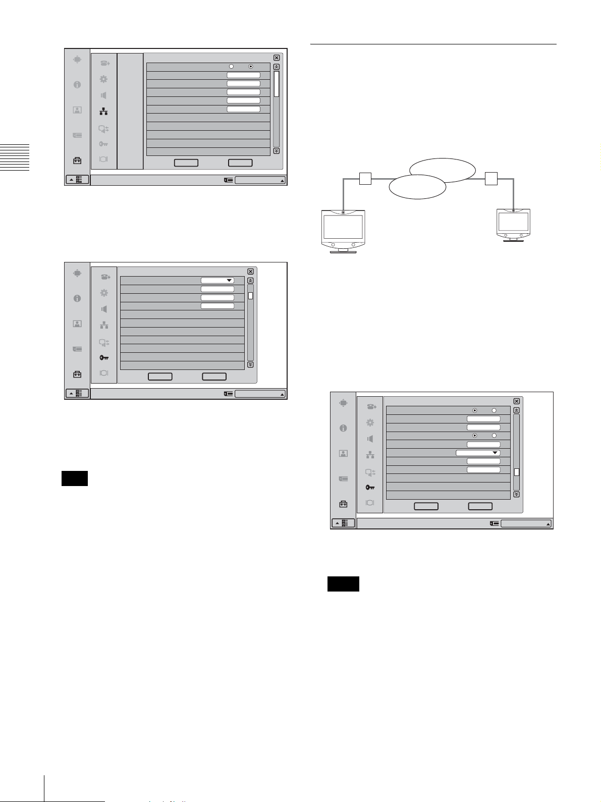
LAN
LAN
DHCP Mode
Host Name
IP Address
Network Mask
Gateway Address
DNS Address
Auto
VCT1
192.100.10.10
255.255.255.0
192.100.10.1
1/3
Off
LAN (PPPoE Connections)
When using PPPoE, you can connect via LAN without a
router.
A modem (using bridge mode) is required when using
FLET’S ADSL.
Configuration example
Chapter 2
3
Registration and Setup
Set “Gatekeeper Mode” to “On” under Page 2/11 of
the Administrator Setup menu, and enter the
Right-click the mouse to display a help message.
CancelOK
IP:192.100.10.10
B FLET’S
ONU
Local IP
network
Internet
ONU
appropriate values for “Gatekeeper Address”, “User
Alias”, and “User Number”.
211.10.10.10
210.10.10.10
Administrator Setup
Gatekeeper Mode On
Gatekeeper Address
User Alias
User Number
192.100.10.20
VP-A
100
2/11
1
Set “PPPoE” to “On” under Page 9/11 of the
Administrator Setup menu, and enter the PPPoE user
name and PPPoE password given to you by the
provider.
If you have a fixed IP from the provider, set “Fixed IP
for PPPoE” to “On”, and enter your fixed IP address
CancelOK
Right-click the mouse to display a help message.
IP:192.100.10.10
The setting has been configured properly if the correct
IP address appears in the launcher menu and
“Registration Confirmed” appears under
“Gatekeeper” in Page 3/4 of the Status & Info menu.
Note
for PPPoE in “Fixed IP Address for PPPoE”.
Administrator Setup
PPPoE
PPPoE User Name
PPPoE Password
Fixed IP for PPPoE
Fixed IP Address for PPPoE
PPPoE DNS
Primary DNS
Secondary DNS
1234567890
210.10.10.10
Obtain Automatically
9/11
On Off
On Off
The information that appears in the launcher menu
may differ depending on the “Number Display” setting
in the Device Setup menu. You can also click the
Number Display portion and select the information to
display from a list.
To conduct a video conference
Select “IP” for the line interface, enter the remote party’s
IP address in the text box, and dial.
You can set “IP” as the default line interface selection for
the launcher menu by setting “Line I/F” to “IP” in the Dial
settings of the Communication Mode menu.
For details on the setting, see “Communication Mode
Menu” on page 33.
50
Setting Up the Network Configurations
CancelOK
Right-click the mouse to display a help message.
IP:012.345.678.912
The setting has been configured properly if the correct
IP address appears in the launcher menu.
Notes
• If the fixed DNS server address is specified by the
provider, set “PPPoE DNS” to “Specify”, and enter
the specific addresses in “Primary DNS” and
“Secondary DNS”.
• The information that appears in the launcher menu
may differ depending on the “Number Display”
setting in the Device Setup menu. You can also click
the Number Display portion and select the
information to display from a list.
2
Remote parties must configure in the same way.
Page 53

To conduct a video conference
Select “IP” for the line interface, enter the remote party’s
IP address in the text box, and dial.
You can set “IP” as the default line interface selection for
the launcher menu by setting “Line I/F” to “IP” in the Dial
settings of the Communication Mode menu.
For details on the setting, see “Communication Mode
Menu” on page 33.
Chapter 2
Registration and Setup
Setting Up the Network Configurations
51
Page 54

Basic Videoconference
This chapter describes how to conduct a videoconference
from start to finish after the administrator has completed
Chapter 3 Basic Videoconference
various registrations and settings for the system.
This chapter describes how to conduct a point-to-point
videoconference via a LAN.
Chapter
3
Starting a Conference by Calling a Remote Party
For use of a “Memory Stick” or optional equipment, see
Chapter 4.
For information on how to conduct a data conference
using the optional ViewPoint 8050-DSB Dual Stream Box,
see chapter 5.
You can start a videoconference with a remote party by
dialing. Once you have made a connection to the remote
party, you can begin talking just as with a normal phone
call and start a videoconference.
For information on making a call in PC (computer
display) mode, see “Calling a Remote Party or Receiving
a Call at the PC Screen” on page 84.
Turning on the Power
1
Turn on the power of any equipment to be used for the
videoconference.
2
Press the (Power) switch on the ViewPoint 8050.
The indicator of the switch lights up in orange and
power to the Videoconferencing Terminal comes on.
When powering on is complete, the indicator lights up
in green.
The launcher menu appears on the display and the
picture of the local camera is also shown.
52
Starting a Conference by Calling a Remote Party
Page 55
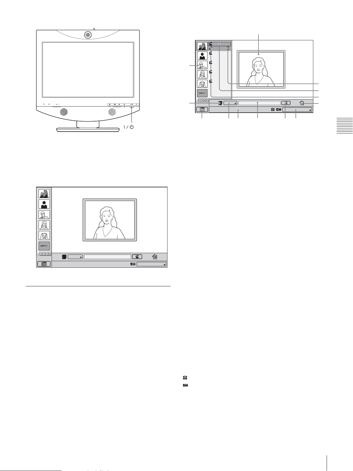
2
1
3
Takanawa
Edit
Takanawa
0657896709
Jamie
XXXXXXXXXX
Marilyn
XXXXXXXXXX
Marvin
XXXXXXXXXX
IP
Point to and click on the icon with the mouse.
IP:
012.345.678.912
qd
qs
qa
0
(Power) switch
3
Make sure that the lens cover of the camera is open.
If it is closed, slide the lever for the lens cover on the
top of the system to the right to open the cover.
The image from the camera appears on the launcher
screen.
IP
Point to and click on the icon with the mouse.
IP:
012.345.678.912
Using the Launcher Menu
4
65789
a Screen
Shows the image from the local camera.
b One Touch Dial list
When you select an entry from the list with the mouse
cursor, buttons appear which let you dial, edit, or delete the
entry.
c Phone Book button
Clicking this button brings up the Phone Book.
If a “Memory Stick” containing Private Phone Book data
is inserted, the Private Phone Book appears.
d Menu bar display button
Clicking this button switches between the launcher menu
and the setup menu screen.
e Line I/F selection
Click this to select the line interface to be used when
dialing.
f Message
Messages for operation guidance etc. appear here.
Chapter 3 Basic Videoconference
The launcher menu appears on the display when the
system is turned on or while it is not connected to a remote
party. The launcher menu displays the image taken by the
local camera, local system status, buttons to open the
menus, and the One Touch Dial list.
g Text box
By entering an IP address here, you can connect directly to
the respective party.
h Dial button
Clicking this button dials the number entered in the text
box.
i System status indicators
These indicators show the status of the local system.
: The system is set to reject calls.
: A “Memory Stick” is inserted.
Number Display: Displays information about the local
system’s line. The information displayed is
determined by the “Number Display” setting in the
Device Setup menu. You can also click the Number
Display portion and select the information to display
from a list.
Starting a Conference by Calling a Remote Party
53
Page 56
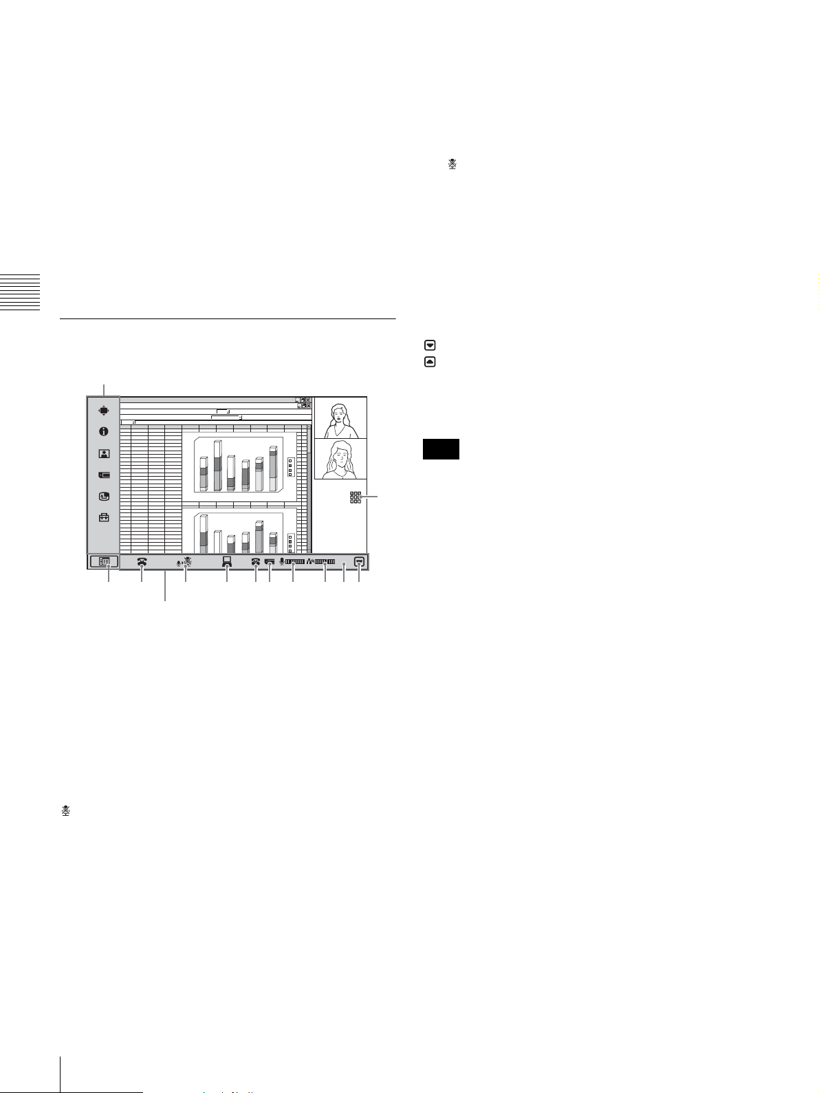
j History button
Clicking this button brings up the incoming/outgoing call
history display.
f Memory stick indicator
Appears when there is a “Memory Stick” inserted in the
memory stick slot.
k Edit button
Clicking this button brings up the List Edit menu for the
selected party.
l Dial button
Clicking this button dials the selected party.
m Delete button
Clicking this button removes the selected party from the
One Touch Dial list.
Chapter 3 Basic Videoconference
Using the Communication Screen
Setup menu bar
ABCDEF GHI J KLMN
1
2
abc d
3
12
46
23
34
4
4
67
5
6
7
8
9
10
11
12
13
14
15
16
17
18
19
20
21
22
23
24
25
abc d
26
27
28
29
30
31
32
33
34
45
5
12
26
6
16
57
69
7
23
44
76
15
4
67
45
5
12
26
6
16
57
12
45
23
46
78
15
69
7
23
1 2 3 4 56 7 8 9 0
Communication control bar
180
56
76
0
6
1
38
0
4
1
13
12
0
2
1
0
0
1
0
6
0
5
0
4
0
2
0
1
180
0
6
1
56
0
4
1
76
23
0
2
1
34
0
0
1
12
13
0
6
0
5
0
4
4
3
2
d
c
b
a
6
5
d
c
b
a
01:25
qa
g Mic level indicator
Shows the microphone input level. When the mic is turned
off, appears instead.
h Packet loss indicator
Shows the LAN line status.
i Elapsed time display
Displays the time elapsed from the start of communication.
j Communication control bar display hide button
By clicking this button, you can switch between hiding and
displaying the communication control bar.
: To hide the menu bar.
: To display the menu bar.
k DTMF button
Click this button to display the DTMF soft keyboard.
Note
The DTMF button appears when “Display DTMF button”
is set to “On” on Page 10/11 of the Administrator Setup
menu.
To display detailed system information
Click the setup menu bar display button to bring up the
menu selection screen. Then click “Status & Info” from the
setup menu. The Status & Info menu which shows various
information about the local system and communication
settings appears.
a Setup menu bar display button
By clicking this button, you can switch between hiding and
displaying the setup menu bar.
b Disconnect button
Click this button to end a communication.
c Mic On/Off button
Clicking this button turns the mic on or off.
The change is reflected in the mic level indicator and the
(Mic Off) button indicator on the main unit as well.
d DSB transmission button
This button is only displayed when a ViewPoint 8050DSB Dual Stream Box is installed.
Click this button to send or cancel data transmissions.
e Do not disturb indicator
Appears when “Do not disturb” in the Answer Setup menu
is set to “On”.
54
Starting a Conference by Calling a Remote Party
Page 57
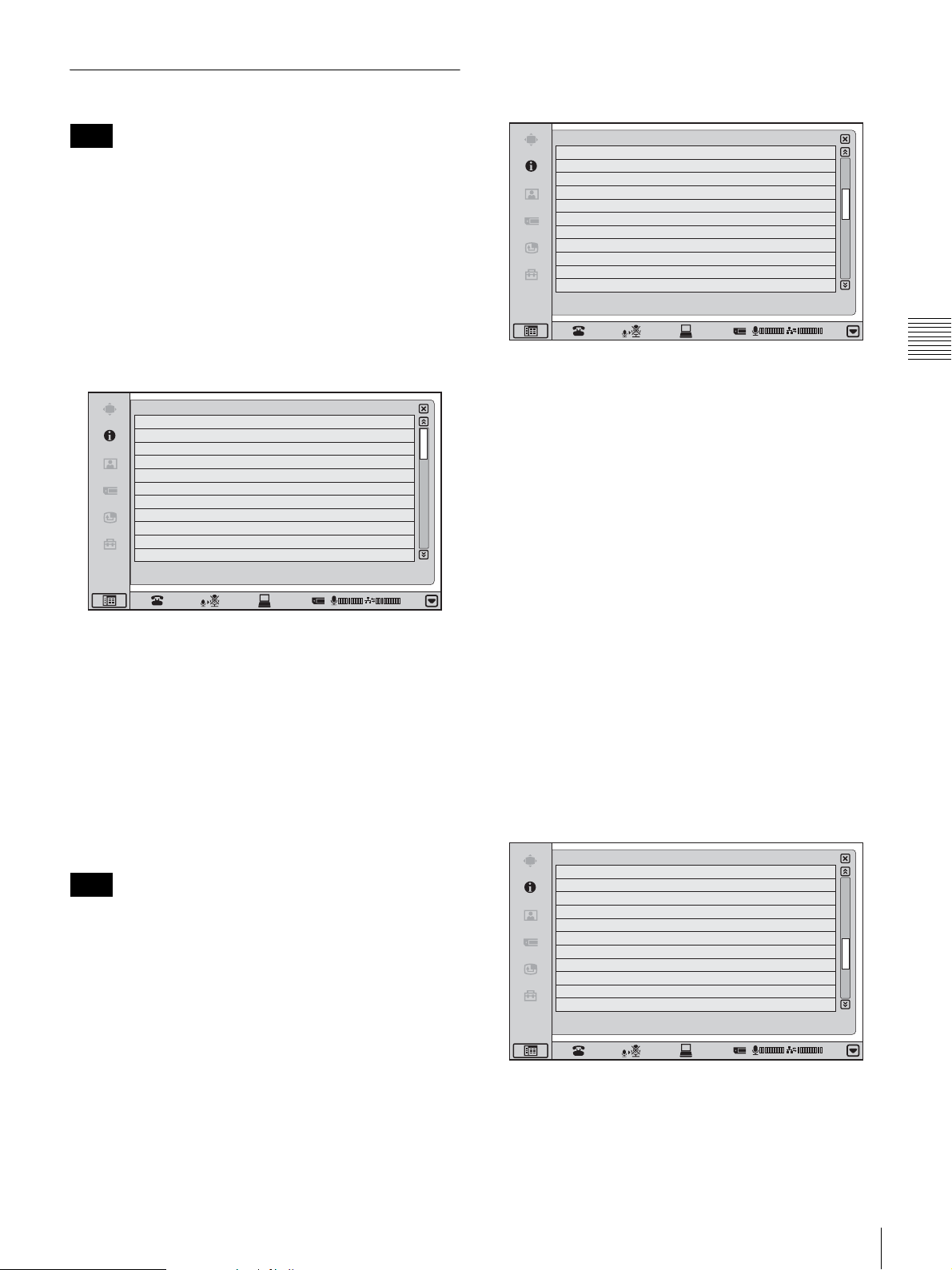
Status & Info Menu
Page 2/4
Note
When communication is not in progress, Page 4/4 appears
first and information on the communication status of the
previous communication is displayed.
However, as information on previous communications is
cleared when the system’s power is turned off, this
information will not appear when the system is turned on
again and no new communications have been held. In such
a case, only Page 3/4 and Page 4/4 will appear.
Page 1/4
Status & Info.
Line I/F
Far End Camera Control
Audio Mode
Video Mode
Frame Rate
Rate
OK
IP
On
MPEG4 AAC(Encode)MPEG4 AAC(Decode)
H.264(Encode) H.264(Decode)
30fps(Encode) 30fps(Decode)
430kbps(Encode) 760kbps(Decode)
Cancel
Line I/F
Shows the line interface that is being used.
1/4
01:25
Status & Info
Bit rate
Audio
Video
H.239
Number of packets
Audio
Video
H.239
Encode Decode
63 kbps 63 kbps
914 kbps 914 kbps
0 kbps 0 kbps
Loss Recovery Reception
0
0
0
OK
Cancel
0 0
0 0
0 0
2/4
01:25
Bit rate - Encode
Displays by category (audio, video, and H.239
(Presentation)) the transfer rates for sending data.
Bit rate - Decode
Displays by category (audio, video, and H.239
(Presentation)) the transfer rates for receiving data.
Number of packets - Loss
Displays by category (audio, video, and H.239
(Presentation)) the number of packets lost during transfer
on the network.
Number of packets - Recovery
Displays by category (audio, video, and H.239
(Presentation)) the number of lost packets that were
recovered with the system’s QoS function.
Chapter 3 Basic Videoconference
Far End Camera Control
Shows whether the far-end camera can be controlled from
the system.
Audio Mode
Shows the currently selected audio coding methods.
Video Mode
Shows the currently selected video coding methods.
Note
The audio coding methods and video coding methods
actually used for communication may be different from the
settings shown, depending on the capabilities and settings
of the videoconference system at the far end.
Frame Rate
Shows the video frame rate in real time.
Rate
Shows the actual transmission rate in real time.
The rate and then settings are shown for 5 seconds when
this page is first shown.
Number of packets - Reception
Displays by category (audio, video, and H.239
(Presentation)) the number of packets received during
communication.
Page 3/4
Status & Info.
LAN Line Status
Gatekeeper
LAN Mode
OK
LAN Line Status
Shows the LAN line status.
Gatekeeper
Shows the gatekeeper status.
Connected
Registration Confirmed
Speed = 100Mbps, Duplex = Full
Cancel
3/4
01:25
Starting a Conference by Calling a Remote Party
55
Page 58
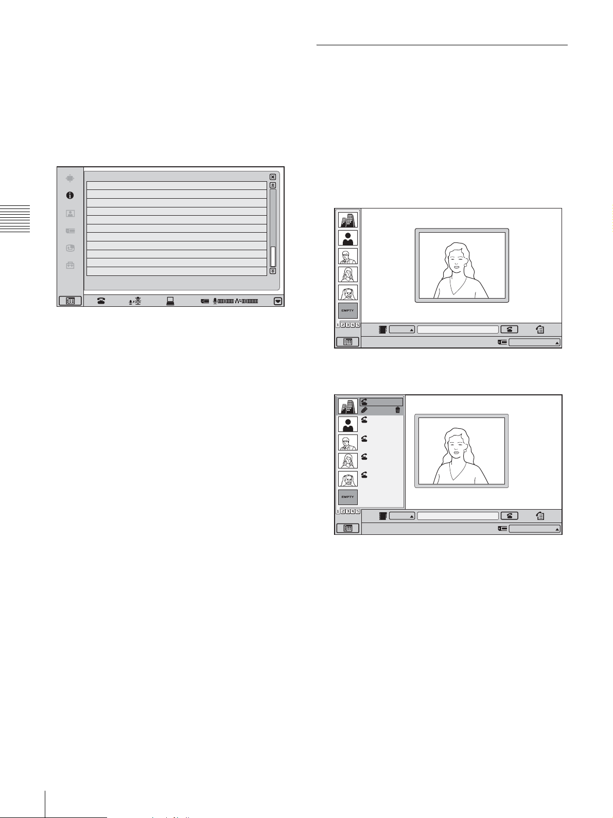
LAN Mode Speed
Shows the LAN connection speed.
LAN Mode Duplex
Shows whether the LAN connection is in Full duplex or
Half duplex.
Calling a Remote Party Using One Touch Dial
This section describes how to call a remote party that has
been registered in the One Touch Dial list.
Page 4/4
Status & Info.
Host Version
DSP Version
LCD version
Camera version
AEC version
Chapter 3 Basic Videoconference
DSM version
Host Name
IP Address
MAC Address
Serial Number
Communication Status
OK
Host Version
Shows the system software version.
DSP Version
Shows the software version of the integrated video/audio
codec DSP (Digital Signal Processor).
LCD Version
Shows the software version of the display panel on the
ViewPoint 8050.
Camera Version
Shows the software version of the camera on the
ViewPoint 8050.
Ver XX.XX
Ver XX.XX
Ver XX.XX
Ver XX.XX
Ver XX.XX
Ver XX.XX
XXXXXX
XXX.XXX.XXX.XXX
XX:XX:XX:XX:XX:XX
XXXX
Connecting
Cancel
4/4
01:25
For information on One Touch Dial registration, see page 46.
1
Click the One Touch Dial tab for the party that you
want to call.
The One Touch Dial group is switched.
IP
Point to and click on the icon with the mouse.
2
Move the mouse cursor to the entry that you want to
IP:
012.345.678.912
call, and click “Dial”.
Takanawa
Edit
Takanawa
0657896709
Jamie
XXXXXXXXXX
Marilyn
XXXXXXXXXX
Marvin
XXXXXXXXXX
AEC Version
Shows the version of the acoustic echo canceller.
DSM Version
Shows the software version of DSB when the
ViewPoint 8050-DSB Dual Stream Box is installed.
Host Name
Shows the host name.
IP Address
Shows the IP address.
MAC Address
Shows the MAC address.
Serial Number
Shows the serial number of the system.
Communication Status
Shows the current communication status of the system.
56
Starting a Conference by Calling a Remote Party
IP
Point to and click on the icon with the mouse.
IP:
012.345.678.912
The selected party is called. The indication “Dialing”
appears on the display.
When the connection is established, the indication
“Communication starts!” appears.
You can now start the videoconference.
Page 59
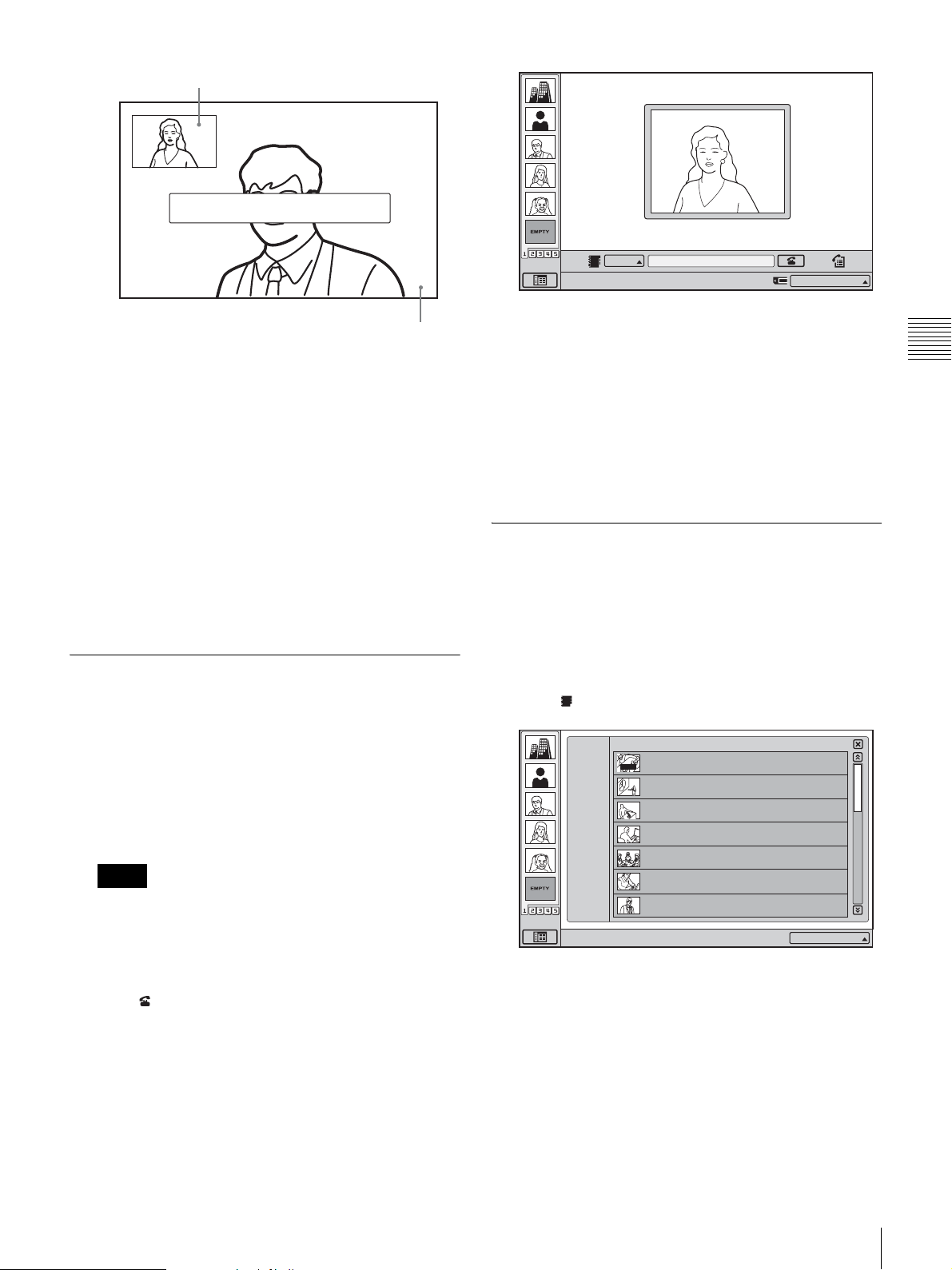
Local image
Communication starts!
123.456.789.012
IP
Point to and click on the icon with the mouse.
IP:
012.345.678.912
Remote party image
To cancel dialing before connecting
Click “Cancel”.
One Touch Dial from the Private Phone Book
Insert the “Memory Stick” in which the Private Phone
Book is registered into the Memory Stick slot of the
system. The Private One Touch Dial list appears in the
launcher menu.
The operations for the Private One Touch Dial list are the
same as those for the One Touch Dial list of the system.
See “Calling a Remote Party Using One Touch Dial” on
page 56.
Calling a Remote Party by Entering the IP Address in the Launcher Menu
1
Select “IP” for the line interface, and enter the IP
address of the remote party in the number entry text
box.
When you click on the text box, the soft keyboard display
appears. Use the display for alphanumeric entry.
Notes
• Click “Backspace” to delete the character
immediately before the cursor.
• Click “Delete all” to delete the entire entry and start
over.
2
Click (Dial).
The entered party is called. The indication “Dialing”
appears on the display.
When the connection is established, the indication
“Communication starts!” appears.
You can now start the videoconference.
To cancel dialing before connecting
Click “Cancel”.
Calling a Remote Party Registered in the Phone Book
This section describes how to call a remote party that has
been registered in the Phone Book.
For information on Phone Book registration, see page 41.
1
Click (Phone Book) in the launcher menu.
Phone Book
ALL
A--I
J--S
T-- Z
0--9
New
Right-click the mouse to display a help message.
AUTO
HQ4Room5
05032105678
Takanawa
0657896709
HQ5Room6
XXXXXXXXXX
HQ5Room6
XXXXXXXXXX
HQ5Room6
XXXXXXXXXX
HQ5Room6
XXXXXXXXXX
HQ5Room6
XXXXXXXXXX
The Phone Book menu appears.
2
Move the mouse cursor to the entry that you want to
call, and click “Dial”.
1/3
IP:012.345.678.912
Chapter 3 Basic Videoconference
The selected party is called. The indication “Dialing”
appears on the display.
When the connection is established, the indication
“Communication starts!” appears.
You can now start the videoconference.
Starting a Conference by Calling a Remote Party
57
Page 60
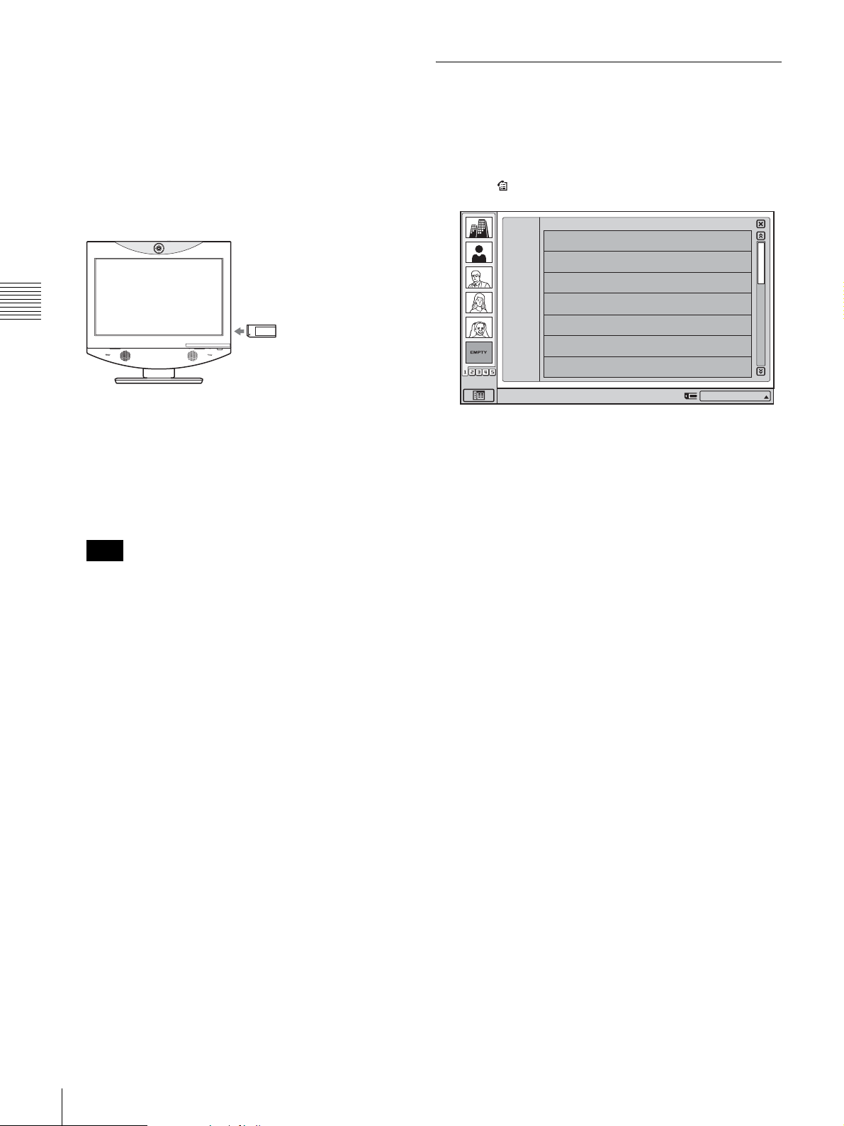
To cancel dialing before connecting
Click “Cancel”.
To call a remote party registered in the
Private Phone Book
1
Insert the “Memory Stick” on which the Private Phone
Book is stored into the Memory Stick slot of the
system.
Chapter 3 Basic Videoconference
Calling a Remote Party From the Incoming/Outgoing Call History
This section describes how to call a remote party from the
History list.
1
Click (History) in the launcher menu.
OUT
ALL
History
2005.07.30 10:10
IN
OUT
OUT
IN
OUT
IN
IN
05032105678
2005.07.30 10:10
0657896709
2005.07.30 10:10
XXXXXXXXXX
2005.07.30 10:10
XXXXXXXXXX
2005.07.30 10:10
XXXXXXXXXX
2005.07.30 10:10
XXXXXXXXXX
2005.07.30 10:10
XXXXXXXXXX
IN
1/3
The Phone Book contents are switched to the Private
Phone Book.
2
Move the mouse cursor to the entry that you want to
call, and click “Dial”.
The selected party is called.
Note
If the “Auto Dial” item for the Private Phone Book is
set to “On”, the system automatically dials the
specified entry when the “Memory Stick” is inserted.
For information on specifying an entry, see “To dial a
specified entry of the Private Phone Book
automatically” on page 44.
To search for an entry in the Phone Book
The Phone Book displays seven entries at a time.
When you select the “ALL” tab, the first seven entries of
the Phone Book are shown.
When you select the “0-9”, “A-I”, “J-S”, or “T-Z” tab, the
first seven entries starting with the respective letter or
numeral are shown.
When there are several pages, a scroll bar will appear at the
right side of the screen. To advance to the next page, click
the Page button at the bottom of the scroll bar. To go back
to the previous page, click the Page button at the top of the
scroll bar.
You can also scroll through pages by moving the scroll bar
with the mouse.
Right-click the mouse to display a help message.
IP:012.345.678.912
The History menu appears.
2
Move the mouse cursor to the entry that you want to
call, and click “Dial”.
The selected party is called. The indication “Dialing”
appears on the display.
When the connection is established, the indication
“Communication starts!” appears.
You can now start the videoconference.
To cancel dialing before connecting
Click “Cancel”.
58
Starting a Conference by Calling a Remote Party
Page 61

Receiving a Call From a
• See pages 61 - 64 to adjust the sound and picture during
the conference.
Remote Party
Operations for answering a call differ depending on the
setting of the answer mode.
Auto answer mode
The system automatically receives a call from a remote
party and you can start conferencing. Although no
operation is necessary to start, the picture on the local site
will be displayed on the remote site screen even if you are
not ready to begin.
Manual answer mode
When there is an incoming call, a ringer tone sounds. You
need to connect the call manually before starting the
conference.
You can start it whenever you are ready.
Note
You cannot answer the call unless the system is turned on.
For setting of the answer mode, see “Auto Answer” and
“Videoconference Button Answer” in the “Answer Setup
Menu” on page 30.
To receive a call in manual answer mode
When you receive a call, a ringer tone sounds and the
message “Incoming call. Answer?” appears on the display.
Click “OK”.
The system is then connected.
Once the connection is established, the picture of the
remote party is displayed on the local system and the sound
is heard. The picture and sound from the local system will
be transmitted to the remote site at the same time.
The message “Communication starts!” appears on the
display.
You are now ready to start a videoconference.
You can also connect the call by pressing the
(Videoconference) button on the unit when
“Videoconference Button Answer” is set to “On” in the
Answer Setup menu.
Note
For information on how to adjust the sound and camera
during a videoconference, see pages 61 - 64.
When you do not want to answer the call
Click “Cancel”. The ringer tone stops.
You can also reject the call by pressing the (PC) button
on the unit when “Videoconference Button Answer” is set
to “On” in the Answer Setup menu.
Chapter 3 Basic Videoconference
For information on receiving a call in PC mode, see
“Calling a Remote Party or Receiving a Call at the PC
Screen” on page 84.
Answering a Call From a Remote Party
To answer a call in auto answer mode
When you receive a call, a ringer tone sounds and the message
“Answering” appears on the display.
The system is automatically connected and the picture of the
remote party is displayed on the local system and the sound is
heard. The picture and sound on the local site will be enabled
on the remote site at the same time.
The message “Communication starts!” appears on the display.
You are now ready to start a conference.
Notes
• If you receive a call when you are using the
Videoconferencing Terminal as a computer display, the
picture of the remote party will appear automatically as
a window picture.
Note
When you reject a call using the (PC) button on the unit,
the screen switches to PC mode. To return to the previous
screen, press the (Videoconference) button on the unit.
To display the elapsed communication
time
You can show the elapsed communication time on the
display if the “Time Display” item in the Device Setup
menu is set to “On”.
To disable this function, set the item to “Off”.
For information on the “Time Display” item, see the
section “Device Setup Menu” on page 30.
Ending the Conference
1
Click the (Disconnect) button.
The indication “Disconnect?” appears on the display.
2
Click “OK”.
Receiving a Call From a Remote Party
59
Page 62
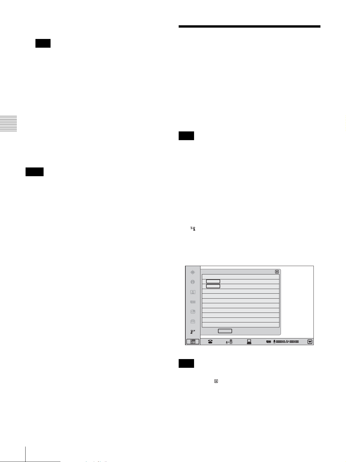
The line is disconnected.
Note
The power of the system remains on even if the line is
disconnected.
To cancel disconnection of the system
Click “Cancel”.
To register the connected remote party in
the Phone Book
You can easily register the remote party who has just
disconnected.
If the “Last Number Registration” item in the Device
Chapter 3 Basic Videoconference
Setup menu is set to “On”, the message “Register this
participant in the list?” appears after a videoconference
with an unregistered remote party is finished. When you
click “OK”, the Edit List menu appears.
Notes
• If the “Last Number Registration” item is set to “Off”,
the message “Register this participant in the list?” does
not appear.
• If a “Memory Stick” containing Private Phone Book data
is inserted, the entry will be saved in the Private Phone
Book.
• If you do not click “OK” when the message appears, the
message will disappear after about 30 seconds, and the
remote party will not be registered to the list.
For information on the “Last Number Registration” item,
see the section “Device Setup Menu” on page 30.
Joining a Multipoint Videoconference
The ViewPoint 8050 can join a multipoint
videoconference as the child terminal to an MCU
(Multipoint Control Unit).
The procedures for initiating and accepting calls are the
same as for a point-to-point videoconference. For details,
see the sections “Starting a Conference by Calling a
Remote Party” on page 52 and “Receiving a Call From a
Remote Party” on page 59.
Note
Because the ViewPoint 8050 does not feature the MCU
function, this system cannot be used to host a multipoint
videoconference.
About broadcast mode
When participating in a multipoint videoconference, the
video from the local system can be broadcast to all other
participants.
To do this, click “Broadcast Mode” at the bottom of the
menu bar, and then click “Start” in the Broadcast Mode
menu.
The indicator appears at the bottom right of the screen
during broadcast.
To stop broadcasting, click “Stop” in the Broadcast Mode
menu.
Broadcast Mode
Self Broadcast
Start
Stop
Back
Note
CANCEL
01:25
To close the Broadcast Mode menu during broadcast, click
the “Back” or button. To stop broadcasting, open the
Broadcast Mode menu again by clicking “Broadcast
Mode” at the bottom of the menu bar, and click “Stop”.
60
Joining a Multipoint Videoconference
Page 63

Adjusting the Picture and
For details on the “Mic on Answer” setting, see the section
“Answer Setup Menu” on page 30.
Sound
Adjusting the Picture Quality
For details on the adjustment steps, see the section
“Adjusting the Picture Quality on the Display” on page
84.
Adjusting the Volume
You can adjust the volume of the sound to be heard during
a videoconference.
Press the (Volume) + button on the ViewPoint 8050 to
increase the volume, and the (Volume) – button to
decrease it.
You can adjust the volume separately for a
videoconference and for computer display, and store the
respective settings.
Note
If increasing the volume results in acoustic feedback,
decrease the volume setting.
To send the sound to the remote party
Press the (Mic Off) button on the ViewPoint 8050 again,
or click (On) on the display.
Synchronizing Audio and Video - Lip Sync Function
During a videoconference, a time lag may occur between
the sound and picture sent to the remote party.
When you activate the Lip Sync function, the system
automatically adjusts the synchronization of audio and
video. However, this may delay the overall transmission
somewhat, because the audio will be delayed to match the
video.
To activate the Lip Sync function, set the “Lip Sync” item
in the Communication Mode Setup menu to “On”.
For details on the “Lip Sync” setting, see the section
“Communication Mode Menu” on page 33.
Note
If there is an audio/video synchronization problem in the
signal sent from the remote party, you have to ask the
remote party to enable the Lip Sync function at their end.
Chapter 3 Basic Videoconference
Cutting Off the Sound Momentarily Mic Off Function
You can momentarily cut off the sound to be sent to the
remote party.
To do this, either press the (Mic Off) button on the
ViewPoint 8050, or click (Off) on the display. The
sound of the local system will not be heard by the remote
party.
To restore the sound
Press the (Mic Off) button on the ViewPoint 8050 again,
or click (On) on the display.
Cutting Off the Sound On Answering
- Mic Off Function
You can cut off the sound to be sent to a remote party when
you have answered a call from the remote party.
To do this, set the “Mic on Answer” item in the Answer
Setup menu to “Off”. Only the picture of the local system
will be sent to the remote party when answering a call.
Reducing Echo - Echo Canceller
The system is equipped with an Echo Canceller function
designed to reduce the echo that can occur during
bidirectional audio transmission.
Adjusting the Picture and Sound
61
Page 64
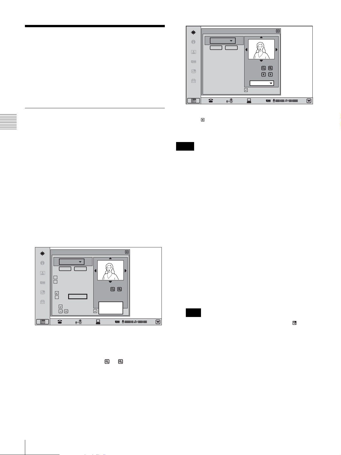
Adjusting the Camera
You can adjust the image shot by the local camera that is
sent to the remote party to obtain the desired angle and
size.
During communication you can also control the camera on
the remote site to adjust the image shot by the remote
camera.
Camera Control
Preset
Save Load
Zoom
Focus
Far system
Control by Far End
01:25
Adjusting the Zoom and Camera Angle
Chapter 3 Basic Videoconference
The zoom and angle can be adjusted from the Camera
Control menu, the camera image during communication,
or the launcher screen when communication is not in
progress.
Adjusting the display using the Camera
Control menu
The remote camera can only be adjusted during
communication.
If the focus adjustment buttons appear on the remote
camera adjustment screen, you can adjust the focus.
1
On the menu selection screen, click “Camera Control”.
The Camera Control menu appears.
Camera Control
Preset
Save Load
Backlight Compensation
Flicker Removal
White Balance
Auto
Start
Adjust
Brightness Adjust
Auto Adjust
2
Select the camera you want to control (“Near system”
or “Far system”).
Zoom
Near system
Far system
Control by Far End
Cancel
01:25
6
Click or the menu bar.
The Camera Control menu closes.
Notes
• When controlling a remote camera, “Far End Camera
Control” must be set to “On” in the Communication
Mode menu of the local system, and the remote system
must be set to receive camera control commands. For
details on setting the remote system, refer to the
operating instructions for each device.
• You cannot control the remote camera during a session
if the remote control format of the remote camera is not
H.281. If you cannot control the remote camera, ask the
remote party about the remote control format of their
camera.
• If the local and remote parties try to control the same
camera at the same time, the camera may not operate
correctly.
Adjusting the display during
communication
1
Right-click on the local or remote image.
Zoom and angle buttons appear on the display.
Note
When the image is from the local camera, a
(Backlight compensation) button appears. Each click
of this button toggles the backlight compensation
function on and off.
3
4
5
62
Adjusting the Camera
To zoom the image, click the or button under the
image.
Click the v/V/b/B symbols at the image edges to
adjust the camera angle.
If you selected to control the remote camera, click the
b/B buttons to adjust the focus.
Page 65

Adjusting the Brightness
Zoom
01:25
2
To zoom the image, click the or button under the
image.
3
Click the v/V/b/B symbols at the image edges to
adjust the camera angle.
When you right-click the camera image window, the
zoom and angle adjustment buttons disappear and the
launcher screen appears again.
Adjusting the display using the launcher
menu when communication is not in
progress
As described above, right-click the camera image. Zoom
and angle buttons will appear on the display. Perform the
adjustment in the preceding section.
The brightness can be adjusted with the Camera Control
menu.
Normally, the brightness is automatically adjusted to
obtain a optimum level. You can also adjust it manually.
It is recommended that the brightness be adjusted
automatically.
Note
Only the brightness of the local camera can be adjusted.
To adjust the brightness
To manually adjust the brightness, deselect the “Auto
Adjust” check box of the “Brightness Adjust” item, and
then click the or button.
Click to brighten the image or to darken it.
To shoot the picture with backlight
compensation
Use backlight compensation when shooting a subject
against a bright background.
To activate backlight compensation, select the “Backlight
Compensation” check box.
For the local camera, backlight compensation can also be
switched on and off by clicking , which appears when
making camera adjustments during communication or
from the launcher menu.
Chapter 3 Basic Videoconference
Note
If the lens cover is closed, camera adjustment is not
possible.
Accepting Remote Camera Control
Deselect the “Control by Far End” check box in the
Camera Control menu to reject control of the camera by
the remote party.
Note
Select whether to adjust the remote camera in “Far End
Camera Control” under “Dial” of the Communication
Mode menu.
Note
If “Auto Adjust” is not selected for “Brightness Adjust”,
backlight compensation will not function.
To eliminate flicker
If a fluorescent lamp is connected to the same power
source as the ViewPoint 8050, flicker may occur in the
camera picture.
To eliminate the flicker, select the “Flicker Removal”
check box.
Using a fixed white balance setting
In the default condition, white balance is adjusted
automatically.
If you want to adjust white balance manually, select the
“Adjust” check box. While draping something white, such
as a piece of paper, in front of the camera, click “Start” and
set the white balance to fit the ambient environment. The
white balance will then be fixed to that setting.
To release the fixed setting
Select the “Auto” check box under “White Balance”.
Adjusting the Camera
63
Page 66

Presetting the Zoom and Angle Settings
Up to six preset settings for zoom and camera angle can be
registered in the Camera Control menu. Once you have
stored the settings, you can easily recall them to move the
camera.
1
In the Camera Control menu, under “Preset”, click the
desired number (1 - 6).
Camera Control
Preset
Preset
1
Save Load
Chapter 3 Basic Videoconference
Note
During a communication session, you can select the
remote camera.
For information on how to bring up the Camera
Control menu and selecting a camera, see “Adjusting
the Zoom and Camera Angle” on page 62.
2
3
4
Backlight Compensation
5
Flicker Removal
6
Cancel
White Balance
Auto
Start
Adjust
Brightness Adjust
Auto Adjust
Right-click the mouse to display a help message.
Zoom
Control by Far End
IP:012.345.678.912
Camera Control
Preset
Preset
1
Save Load
2
3
4
Backlight Compensation
5
Flicker Removal
6
Cancel
White Balance
Auto
Start
Adjust
Brightness Adjust
Auto Adjust
Right-click the mouse to display a help message.
Zoom
Control by Far End
IP:012.345.678.912
Note
During a communication session, you can select the
remote camera.
For information on how to bring up the Camera
Control menu and selecting a camera, see “Adjusting
the Zoom and Camera Angle” on page 62.
2
Click “Load”.
The setting of the preset number is recalled and the
camera moves to the position of that setting.
About stored adjustment settings
The ViewPoint 8050 retains the settings for camera zoom
and angle, brightness, backlight compensation on/off and
flicker on/off in non-volatile memory.
When you turn off the system and turn it on again, the
camera will be adjusted using the stored settings.
2
Adjust the zoom and angle.
For information on how to make the adjustment, see
“Adjusting the Zoom and Camera Angle” on page 62.
3
Click “Save”.
The setting is registered in the selected preset number.
Recalling a Preset Zoom and Angle Setting
You can use the Camera Control menu to recall a preset
zoom and camera angle setting.
1
In the Camera Control menu, under “Preset”, click the
desired number (1 - 6).
64
Adjusting the Camera
Page 67
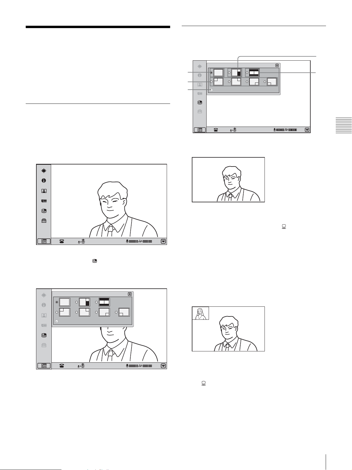
Changing the Screen
3
Layout
During a communication session, you can use the Screen
Layout Setup menu to control the way video is shown on
the display.
Bringing up the Screen Layout Setup Menu
1
During a communication session, click the menu bar
display button.
The menu bar appears.
Switching the Display
Screen Layout Setup
1
2
5
a Full screen
Display the remote H.239 image
01:25
4
Chapter 3 Basic Videoconference
2
In the menu bar, click (Screen Layout Setup).
The Screen Layout Setup menu appears.
The screen changes when you select a screen layout.
Screen Layout Setup
Display the remote H.239 image
01:25
01:25
Only the remote video is shown as a full-screen
display. When still images are sent or received,
presentation data is received, or the (PC) button is
pressed to display the computer screen, the display
switches to Picture-and-Picture mode. The transmitted
or computer images are shown as full-screen displays,
with the remote video and local video shown as
window pictures.
When the “Display the remote H.239 image” check
box is not selected, however, presentation data that is
received will not display on the unit’s screen.
b Picture-in-Picture
The remote video is shown as a full-screen display and
the local video as a window picture. When still images
are sent or received, presentation data is received, or
the (PC) button is pressed to display the computer
screen, the transmitted or computer images are shown
as full-screen displays, with the remote video shown as
a window picture.
The display position of the window picture can be set
to top left, top right, bottom right, and bottom left.
Changing the Screen Layout
65
Page 68
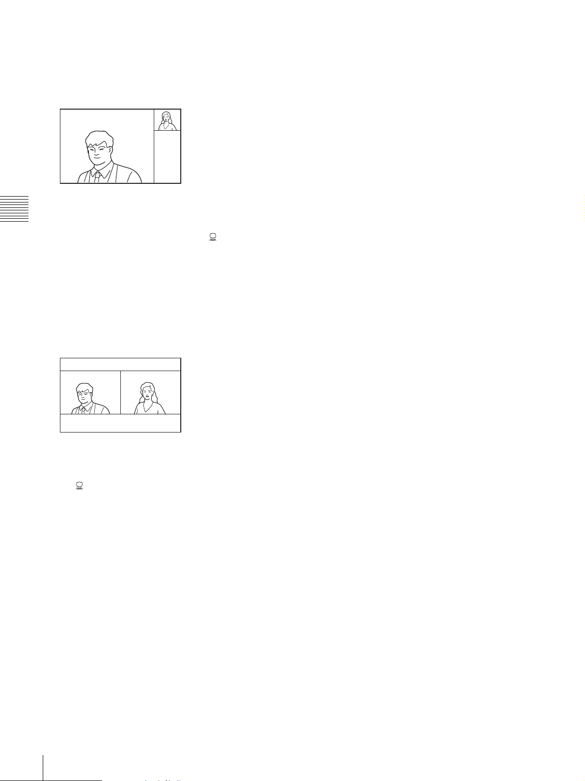
When the “Display the remote H.239 image” check
box is not selected, however, presentation data that is
received will not display on the unit’s screen.
c Picture-and-Picture
The remote video is shown as a full-screen display on
the left and the local video as a window picture on the
Chapter 3 Basic Videoconference
right. When still images are sent or received,
presentation data is received, or the (PC) button is
pressed to display the computer screen, the transmitted
or computer images are shown as full-screen displays,
with the remote video and local video shown as
window pictures.
When the “Display the remote H.239 image” check
box is not selected, however, presentation data that is
received will not display on the unit’s screen.
d Side-by-side
The remote video is shown on the left and the local
video on the right, at the same size. When still images
are sent or received, presentation data is received, or
the (PC) button is pressed to display the computer
screen, the transmitted or computer images are shown
on the left and the remote video on the right.
When the “Display the remote H.239 image” check
box is not selected, however, presentation data that is
received will not display on the unit’s screen.
e Display the remote H.239 image
This check box can be selected when a ViewPoint
8050-DSB Dual Stream Box is installed on the unit.
When this check box is not selected, presentation data
that is received is output only from the RGB OUT on
the Dual Stream Box. In such a case, you can display
the remote video on the unit’s screen in full-screen (on
the left side during side-by-side display).
66
Changing the Screen Layout
Page 69
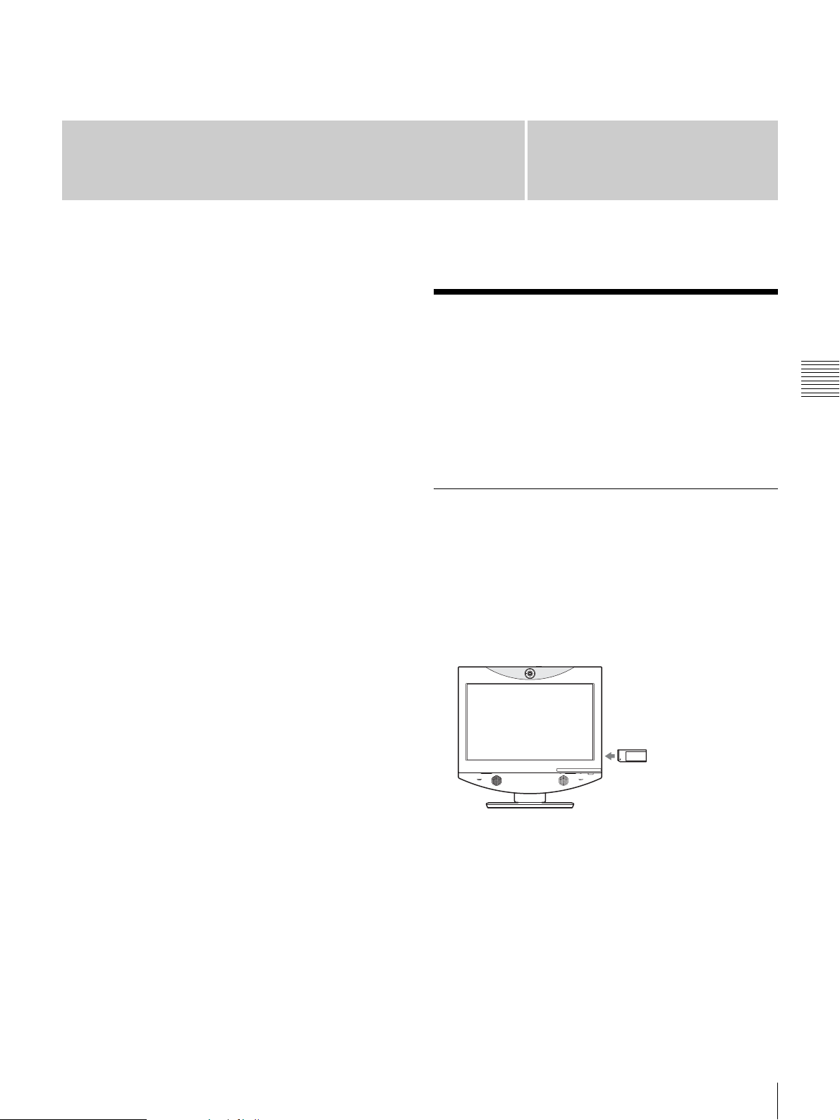
Videoconference With
Optional Equipment
This chapter describes the various videoconferences using
the optional equipment in addition to the components
contained in the ViewPoint 8050 Videoconferencing
Terminal.
For information on conducting a data conference using the
optional ViewPoint 8050-DSB Dual Stream Box, see
Chapter 5.
Chapter
4
Using Still Images Stored in a “Memory Stick” for a Videoconference
You can display the still images stored in the optional
“Memory Stick” or transmit them to a remote party.
Displaying a Still Image Stored on a “Memory Stick”
1
Insert the “Memory Stick” containing the still images
into the Memory Stick slot on the Videoconferencing
Terminal.
Chapter 4 Videoconference With Optional Equipment
Insert the “Memory Stick” with the front facing you
and in the direction of the arrow on it.
2
Display the Image viewer menu.
Click the menu bar display button to bring up the menu
selection screen. Then click “Image viewer”.
Using Still Images Stored in a “Memory Stick” for a Videoconference
67
Page 70
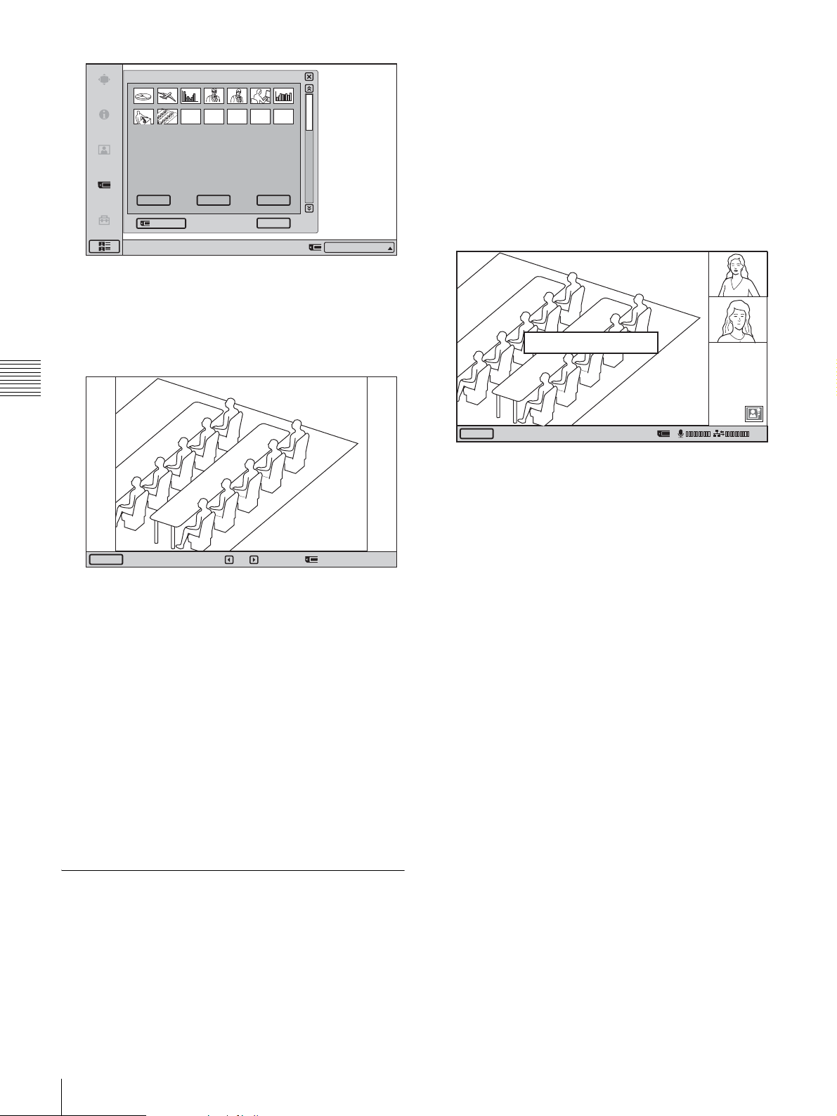
Image viewer
1/3
For information on how to insert a “Memory Stick”
and how to display the Image viewer menu, see
“Displaying a Still Image Stored on a “Memory
Stick”” on page 67.
2
Select the still image you want to send, and click
“Send”.
Load Send Delete
Format
Right-click the mouse to display a help message.
3
Select the still image you want to display, then click
Close
IP:012.345.678.912
“Load”.
The menu disappears and the selected still image is
displayed.
Chapter 4 Videoconference With Optional Equipment
Back
To display a different image
While a still image is displayed, you can click b to return
to the previous image or B to go to the next image.
The selected still image is displayed, and is sent to the
remote party. The message “The still image has been
sent.” appears on the display.
The still image has been sent.
Clear
To cancel still image display
Click “Clear”.
01:25
To delete a still image
On the Image viewer menu, select the image you want to
delete, and click “Delete”. Click “OK” when the message
“Delete File?” appears. The selected still image is deleted
from the “Memory Stick”.
To remove the “Memory Stick”
Carefully push the “Memory Stick” in. This causes it to
pop out slightly, and you can then remove it.
Sending a Still Image Stored on a “Memory Stick”
During a communication session, you can send still images
stored on a “Memory Stick” to the remote party.
1
Insert a “Memory Stick” into the Memory Stick slot on
the Videoconferencing Terminal, and display the
Image viewer menu.
68
Using Still Images Stored in a “Memory Stick” for a Videoconference
Page 71
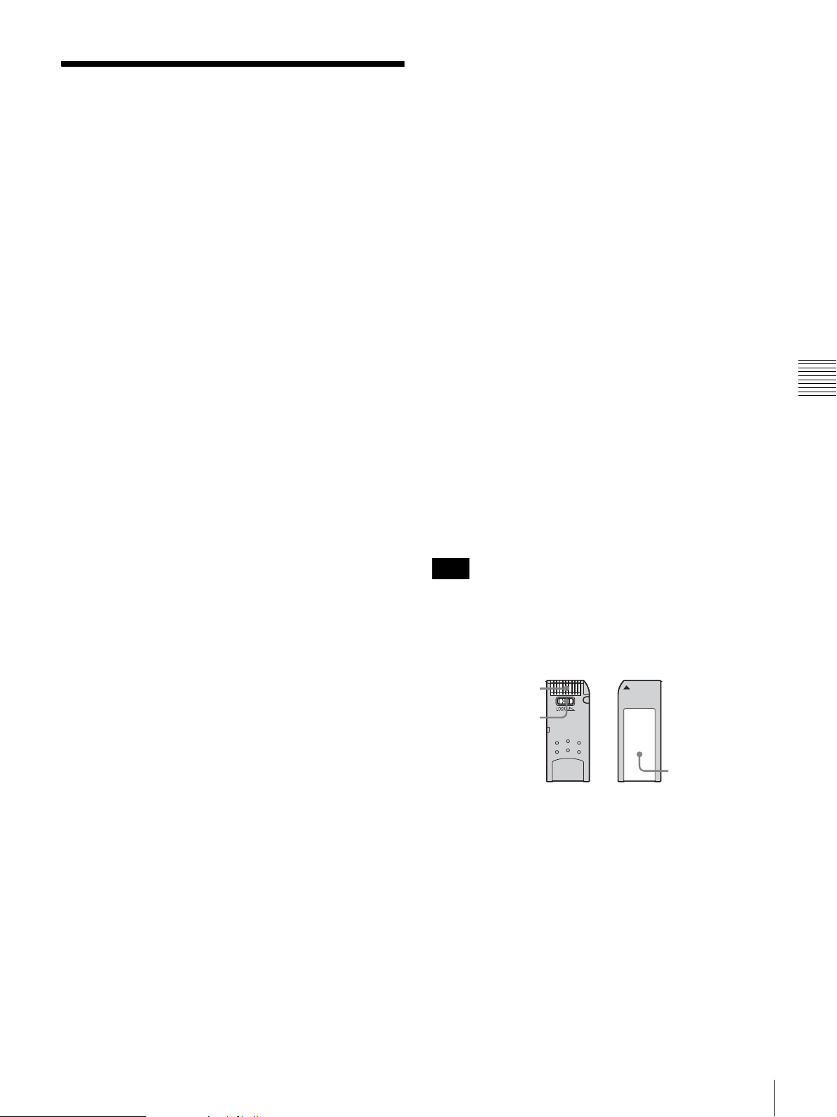
About “Memory Stick”
What is “Memory Stick”?
“Memory Stick” is a compact, portable and versatile IC
(Integrated Circuit) recording medium with a data capacity
that exceeds a floppy disk. “Memory Stick” is specially
designed for exchanging and sharing digital data among
“Memory Stick” compatible products. Because it is
removable, “Memory Stick” can also be used for external
data storage.
“Memory Stick” is available in two sizes: standard size
and compact “Memory Stick Duo” size. Once attached to
a Memory Stick Duo adapter, “Memory Stick Duo” turns
to the same size as standard “Memory Stick” and thus can
be used with products compliant with standard “Memory
Stick.”
Types of “Memory Stick”
There are five types of “Memory Stick” depending on
various uses.
• “Memory Stick PRO”
The “Memory Stick PRO” is a “Memory Stick” that
allows faster data transfer rates in devices that support it.
It also incorporates MagicGate copyright protection
technology.
•“Memory Stick-R”
Data stored in this type of “Memory Stick” is not
overwritten. It can be used only with equipment
compatible with “Memory Stick-R”. Data that requires
MagicGate copyright protection technology cannot be
stored on this type.
•“Memory Stick”
Any type of data except copyright-protected data that
requires MagicGate copyright protection technology can
be stored.
• “MagicGate Memory Stick”
Equipped with the MagicGate copyright protection
technology.
•“Memory Stick-ROM”
Stores pre-recorded, read-only data. Recording or
erasing data cannot be done with this type.
• “Memory Stick” (with memory select function)
Equipped with multiple memories (128 MB). You can
select the memory to use with the memory select switch
on the back of the “Memory Stick”. You cannot use
different memories simultaneously or continuously.
Available types of “Memory Stick” for the
unit
You can use “Memory Stick PRO”, “Memory Stick”, and
“MagicGate Memory Stick” with the unit. However,
because the unit does not support the MagicGate
standards, data recorded with the unit is not subject to
MagicGate copyright protection.
Notes on “Memory Stick Duo”
• To use “Memory Stick Duo” with this unit, attach it to
the Memory Stick Duo adapter before inserting it into
the unit.
• Be sure to attach “Memory Stick Duo” to the adapter
with the correct orientation.
• Be sure to insert the Memory Stick Duo adapter with the
correct orientation. Otherwise, the unit may be damaged.
• Do not insert the Memory Stick Duo adapter without
“Memory Stick Duo” attached. Doing so may result in
malfunction of the unit.
What is MagicGate?
MagicGate is copyright protection technology that uses
encryption technology.
Chapter 4 Videoconference With Optional Equipment
Format that can be displayed with this unit
The unit can display the picture files recorded on a
“Memory Stick” in the following format:
• Image files (DCF-compatible) compressed in the JPEG
(Joint Photographic Experts Group) format (extension:
.jpg)
• Image files of up to 2048 × 1536 pixels can be displayed.
Note
Progressive JPEG is not supported.
Before using a “Memory Stick”
Terminal
Write-protect tab
Labelling position
• When you set the “Memory Stick” write-protect tab to
“LOCK,” data cannot be recorded, edited, or erased.
• Use a sharp object, such as a ballpoint pen, to move the
“Memory Stick Duo” erasure prevention switch.
• Data may be damaged if:
- You remove the “Memory Stick” or turn off the unit
while it is reading or writing data.
- You use the “Memory Stick” in a location subject to
the effects of static electricity or electric noise.
About “Memory Stick”
69
Page 72
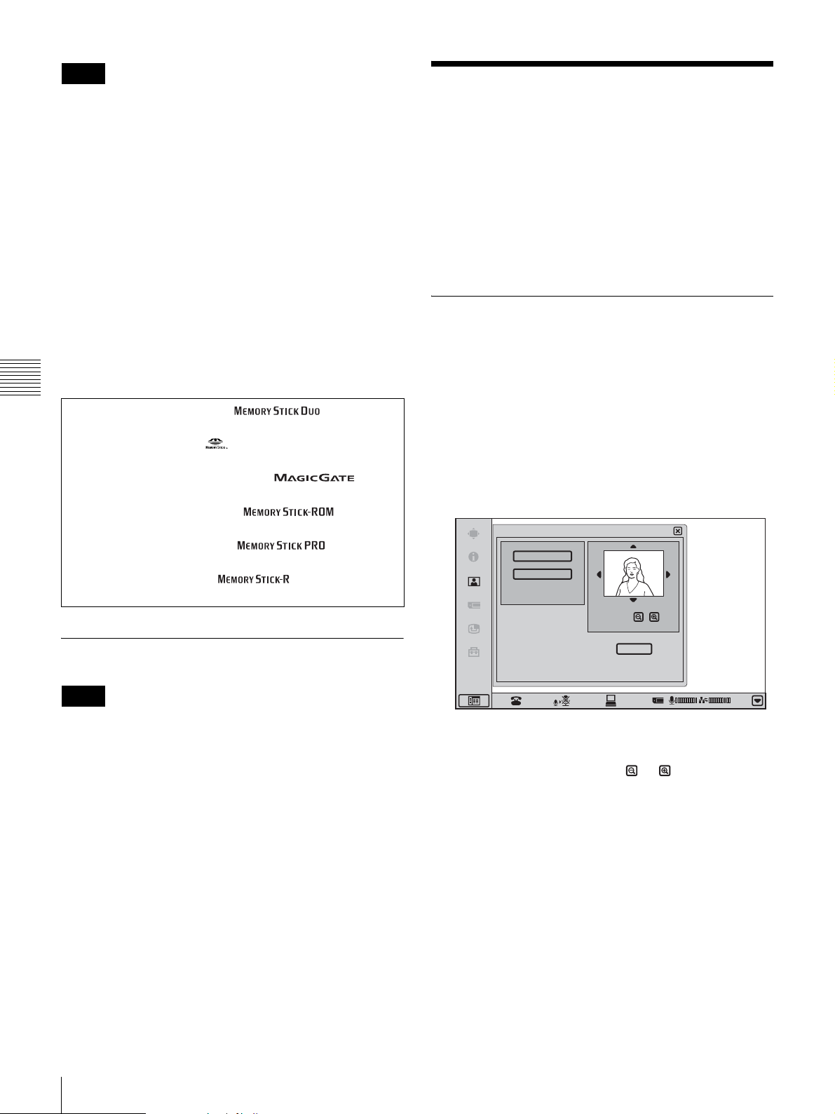
Notes
• Do not attach any other material than the supplied label
onto the label space.
• Attach the label so that it does not stick out beyond the
labelling position.
• Do not write forcefully on the “Memory Stick Duo”
memo area.
• Carry and store the “Memory Stick” in its case.
• Prevent metallic objects or your finger from coming into
contact with the metal parts of the connecting section.
• Do not strike, bend, or drop the “Memory Stick.”
• Do not disassemble or modify the “Memory Stick.”
• Do not allow the “Memory Stick” to get wet.
• Do not use or store the “Memory Stick” in a location that
is:
- extremely hot, such as in a car parked in the sun.
- under direct sunlight.
- very humid or subject to corrosive substances.
Chapter 4 Videoconference With Optional Equipment
• “Memory Stick Duo” and are
trademarks of Sony Corporation.
• “Memory Stick” and are trademarks of Sony
Corporation.
• “MagicGate Memory Stick” and are
trademarks of Sony Corporation.
• “Memory Stick-ROM” and are
trademarks of Sony Corporation.
• “Memory Stick PRO” and are
trademarks of Sony Corporation.
• “Memory Stick-R” and are trademarks of
Sony Corporation.
Sending Motion Pictures as Still Images
You can send motion pictures shot by the Camera as still
images.
When you are sending pictures that contain lots of text
during a video conference, it is recommended that you
send them as still images. The images become clearer than
motion pictures and the texts are easy to read.
Sending Still Images Using the Still Image Menu
While in communication with the remote party, you can
send motion pictures shot by the local camera as still
images. You can send one still image or still images
continuously.
1
Display the Still Image menu.
Click the menu bar display button to bring up the menu
selection screen. Then click “Still Image”.
Still Image
Send
Continuous Send
Zoom
Formatting a “Memory Stick”
Notes
• A “Memory Stick” formatted with a computer cannot be
guaranteed on the Videoconferencing Terminal. Make
sure to use a “Memory Stick” that has been formatted
with this system.
• If you format a “Memory Stick”, all data, including the
still images and Phone Book, will be lost.
• Depending on the type of “Memory Stick” used, it may
take a few moments before the “Memory Stick” is ready
for use after it is inserted.
To format a “Memory Stick”
Click “Memory Stick Format” in the Image viewer menu.
The message “Format a Memory Stick?” appears. When
you click “OK”, the “Memory Stick” will be formatted.
Save
2
Adjust the camera zoom and angle.
3
To zoom the image, click the or button under the
image.
4
Click the v/V/b/B symbols at the image edges to
adjust the camera angle.
5
Click “Send” or “Continuous Send”.
01:25
70
Sending Motion Pictures as Still Images
Page 73
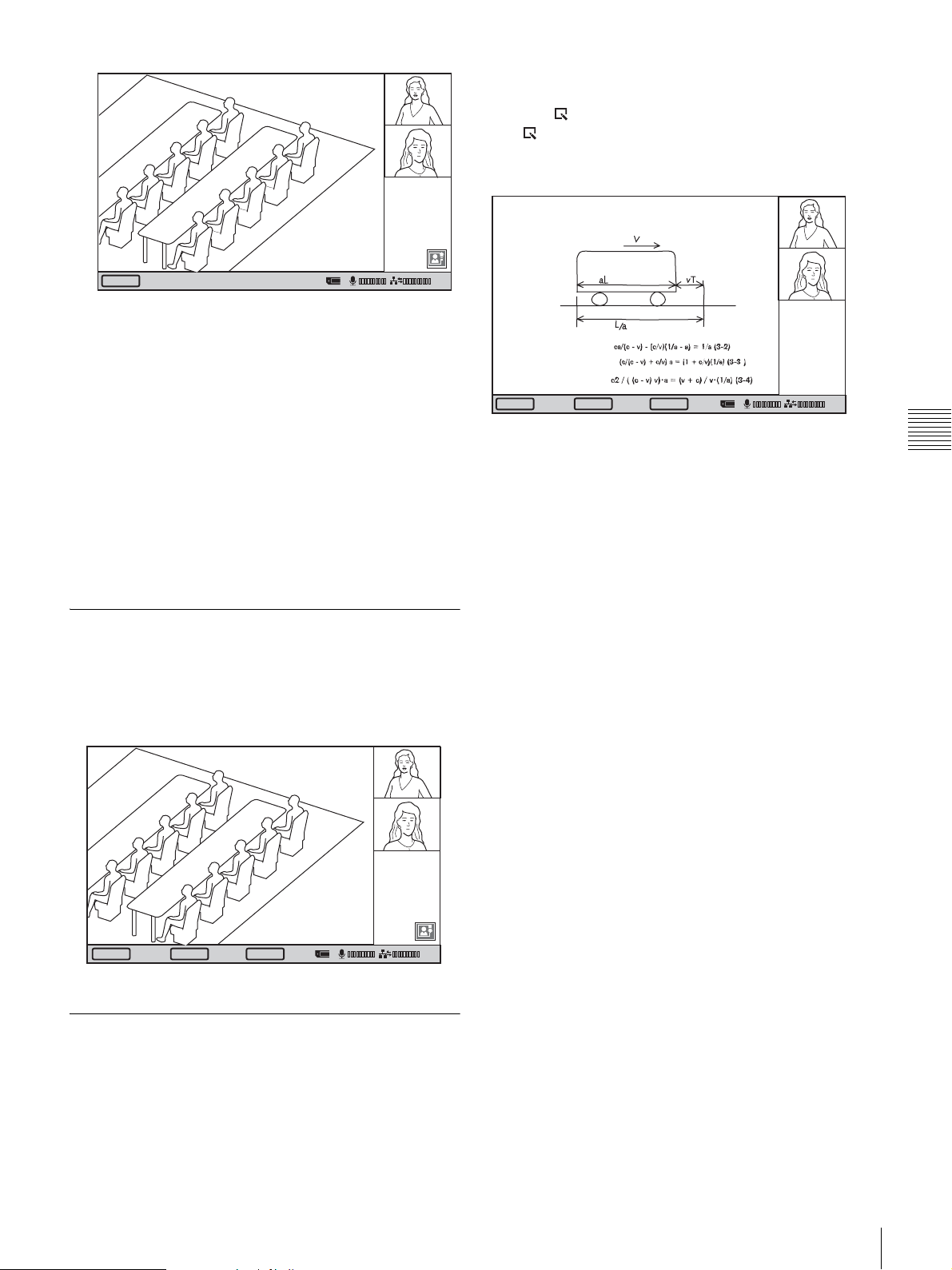
You can return to the normal communication screen by
clicking “Back”. To display the whiteboard image again,
click the (Whiteboard) icon.
The (Whiteboard) icon appears on the bottom right of
the communication screen only when receiving
whiteboard images.
Clear
01:25
The local display freezes, and a still picture will be
sent to the remote party.
If you select “Send”, a single image is sent. When
transmission is finished, the message “The still image
has been sent.” appears.
If you select “Continuous Send”, still images are sent
continuously. The sending interval depends on the
transmission rate and the image type.
To stop “Continuous Send”
Click “Clear”.
To cancel still image display
Click “Clear”.
Receiving Still Images
When you receive a still image from a remote party, the
image is shown as a full-screen display.
Click “Save” to save the still image to a “Memory Stick”,
and click “Clear” to return to the communication screen.
Back
Save
Disconnect
01:25
Chapter 4 Videoconference With Optional Equipment
SaveClear
Disconnect
01:25
Receiving Whiteboard Images
When a remote party is using a whiteboard during a
videoconference, whiteboard images received from the
remote party are shown in full-screen display.
Click “Save” to save received whiteboard images to a
“Memory Stick.”
Sending Motion Pictures as Still Images
71
Page 74
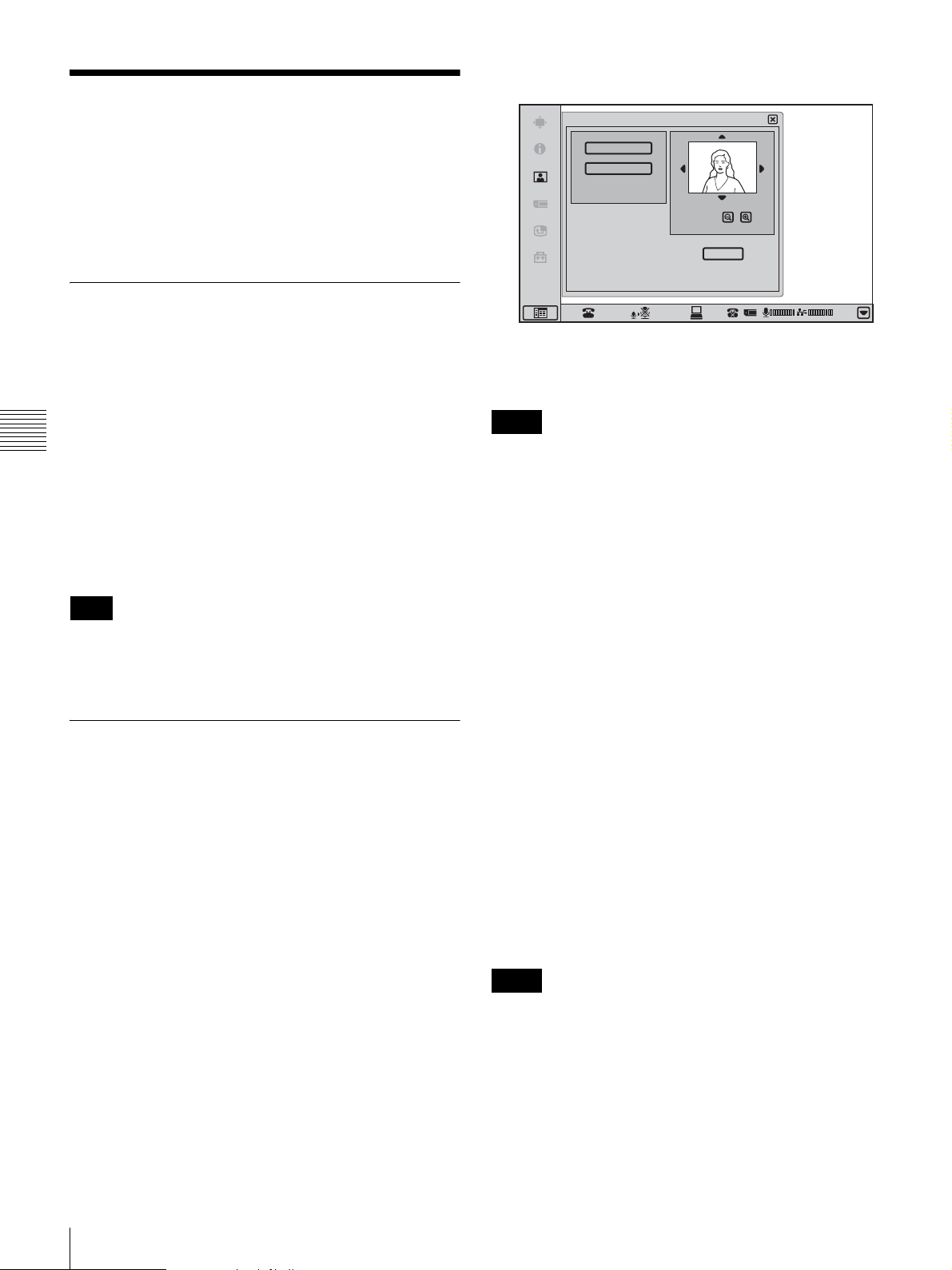
2
Click “Save”.
Saving Still Images
When a “Memory Stick” is inserted beforehand, you can
easily store still images sent from the remote party or still
images from the local camera onto the “Memory Stick”.
You can use the saved images for One Touch Dial buttons
and Phone Book.
Saving Remote Party Pictures
Automatically – Automatic Image
Capture Feature
The system automatically captures still images of the
remote party ten times every five seconds from the
beginning of each communication, and saves them in the
built-in memory. The still images stored in the memory are
Chapter 4 Videoconference With Optional Equipment
retained until the next communication starts or the power
of the system is turned off.
This feature is activated when the “Memory Stick” is not
inserted.
Stored images can be used as thumbnail images for One
Touch Dial and the Phone Book.
Note
If it has taken a long time from dialing to establish the
connection, the first captured images may be black. This is
not a problem.
Still Image
Send
Continuous Send
Zoom
Save
01:25
The picture on the display will be saved on the
“Memory Stick” as a still image.
Notes
• Do not remove the “Memory Stick” until the data is
completely loaded. If you do, the “Memory Stick” may
be damaged or the system may cause a malfunction.
• A still image file is saved as a new file. It will not be
overwritten.
When the write-protect tab on the “Memory Stick”
is set to “LOCK”
The message “Memory Stick write-protected” appears and
you cannot save the still image file.
When the memory of the “Memory Stick” is full
The message “Memory Stick full.” appears and you cannot
save the still image file.
Saving Still Images Using the Still Image Menu
1
Display the Still Image menu.
Click the menu bar display button to bring up the menu
selection screen. Then click “Still Image”.
Image format that can be stored in a
“Memory Stick”
File name
The image file is saved under the directory named
“\DCIM\100MSDCF” with a file name as
“DSCXXXXX.JPG”.
Compression format
This system compresses and records the recorded image
data in the JPEG (Joint Photographic Experts Group)
format. The file extension is “.jpg”.
Notes
• This system is not compatible with progressive JPEG
format data.
• If a folder named with a larger number than 100 exists,
the image file is saved in that folder.
72
Saving Still Images
Page 75
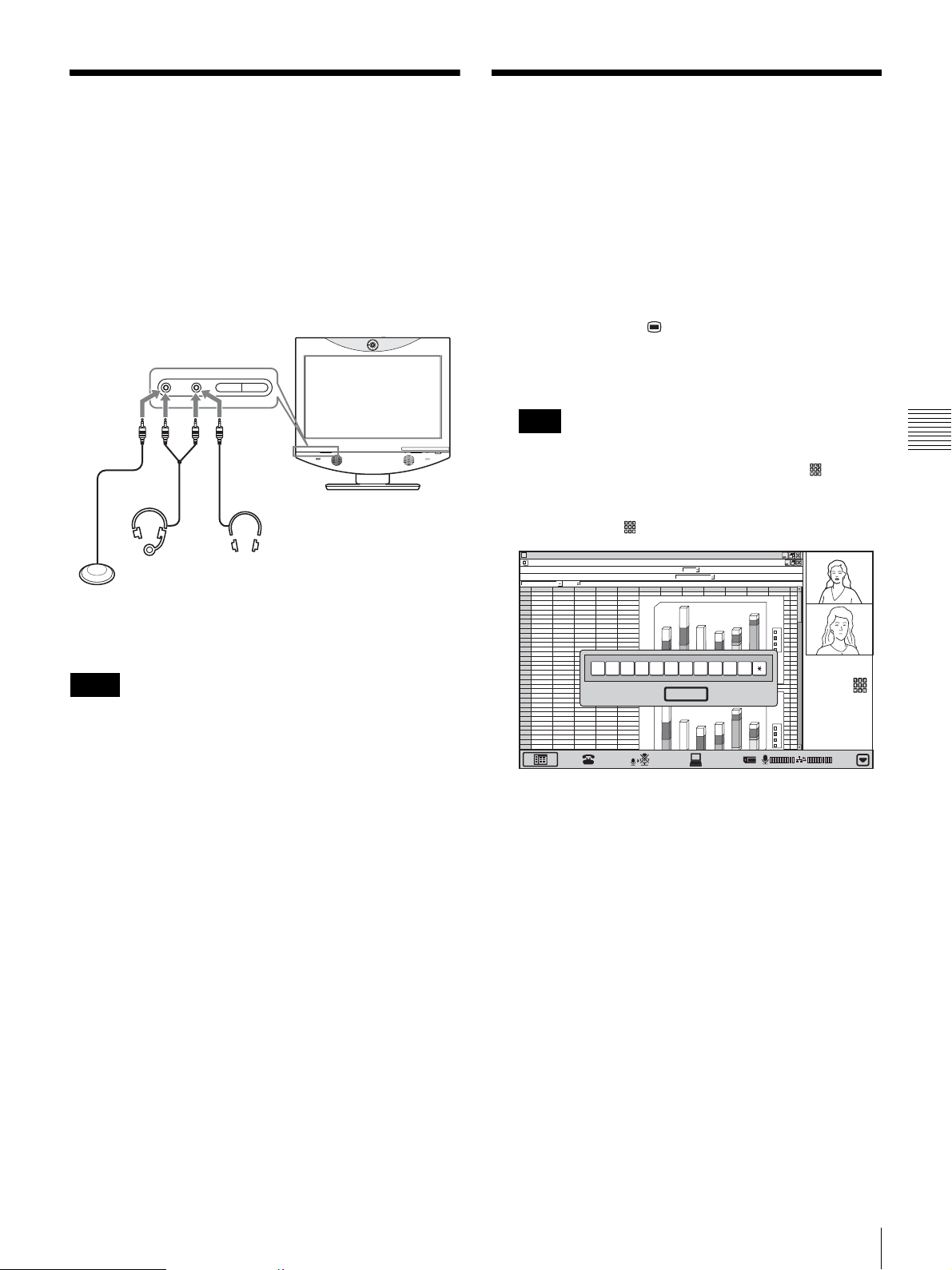
Using External
Controlling the Remote
Microphone and
Headphones
The built-in microphone of the ViewPoint 8050 is
designed for individual use. The commercially available
external microphones can also be connected.
A pair of headphones or a headset can also be used.
to m
to m to i
Headset
(commercially
Microphone
available)
(commercially
available)
Notes
• The built-in microphone is disabled when an external
microphone is connected.
• The built-in speakers are disconnected when headphones
are connected.
to i
Headphones
(commercially
available)
System With Tone Signals DTMF Transmission
When dialing, tone signals (DTMF: Dual Tone Multi
Frequency) assigned to the numbers for (0-9,#,*) can also
be sent. Some systems are designed to allow remote
control using these tones.
1
Press and hold the (Menu) button for 3 seconds
during a communication session.
The DTMF soft keyboard appears on the display.
Note
When “Display DTMF button” is set to “On” on Page
10/11 of the Administrator Setup menu, the (DTMF
button) appears on the right side of the communication
screen. You can also display the DTMF soft keyboard
by clicking the (DTMF button).
ABCDEF GH I J KLMN
1
2
abc d
3
12
46
23
34
4
4
67
5
5
12
6
6
16
7
69
7
8
44
76
9
10
11
12
13
14
15
16
17
18
19
20
21
22
23
24
25
abc d
26
67
4
27
12
5
28
16
6
29
45
12
30
78
46
31
7
69
32
33
34
45
26
57
23
15
1234567890
45
26
57
23
15
23
180
56
76
0
6
1
38
0
4
1
13
12
0
2
1
0
0
1
0
6
0
5
0
4
0
2
0
1
180
0
16
56
0
14
76
23
20
1
34
00
1
12
13
0
6
0
5
0
4
2
Close
4
3
d
c
b
a
#
6
5
d
c
b
a
01:25
Chapter 4 Videoconference With Optional Equipment
Notes on installation of the microphones
• Install an external microphone more than 1 m (3.3 feet)
away from this system.
• Keep the microphone about 50 cm (19 3/4 inches) away
from the participants.
• Place the microphone in a quiet, echo-free location.
• Install the microphone away from equipment that may
cause noise.
• Avoid covering a microphone with paper, etc., or
moving it. If you do either, extreme noise and echo may
be heard temporarily by the remote party.
Using External Microphone and Headphones /
2
Click the numbers buttons that you want to send (09,#,*).
When you click a button, the corresponding tone
signal is transmitted to the remote party.
3
To stop transmitting tone signals, click “Close”.
The DTMF soft keyboard disappears.
Controlling the Remote System With Tone Signals - DTMF Transmission
73
Page 76

Accessing the Videoconferencing Terminal
The following controls are available to access the
Videoconferencing Terminal. For details on each control,
consult your HUAWEI dealer.
Using the Web Monitor Function
Images from the unit can be monitored from a Web
browser.
To enable monitoring of the unit’s images, set “Web
Monitor” to “On” in the Administrator Setup menu (page
35).
Chapter 4 Videoconference With Optional Equipment
For details on access and passwords, see “Administrator
Setup Menu” on page 35.
Using a Web Browser
Accessing the IP address of the Videoconferencing
Terminal from a Web browser allows you to control or set
up the System.
To permit accessing the Terminal, set “Web Access” to
“On” in the Administrator Setup menu (page 35).
For details on the password to access or Web control
feature, see “Administrator Setup Menu” on page 35.
Using Telnet
Accessing the IP address of the Videoconferencing
Terminal from Telnet allows you to control or set up the
System.
To permit accessing the Terminal, set “Web Access” to
“On” in the Administrator Setup menu (page 35).
For details on the password to access or Web control
feature, see “Administrator Setup Menu” on page 35.
74
Accessing the Videoconferencing Terminal
Page 77

Data Conference Using
Dual Stream Box
This chapter shows you how to use the optional ViewPoint
8050-DSB Dual Stream Box to incorporate the screen display
data of a computer or similar into a videoconference.
The optional ViewPoint 8050-DSB Dual Stream Box is
designed for internal installation in the ViewPoint 8050. It
allows sending the pictures or text data displayed on a
computer connected to the ViewPoint 8050 to the remote
party in a videoconference. You can also connect a projector
to the Dual Stream Box and display a high-resolution
computer screen image sent by the remote party at the local
site.
Even if no Dual Stream Box is installed or if another
videoconferencing system is used, the receiving party can
view the computer images sent from the other party.
However, the quality of the picture received will vary
depending on the components of the system. If the Dual
Stream Box is installed, a higher frame rate (number of
frames per second) is possible, which allows viewing highresolution moving images from a computer. To display the
computer images sent from the other party during PC
mode, press the (Videoconference) button on the
system and switch to videoconference mode.
Chapter
and the ViewPoint 8050 should be set up to be a separate
segment.
As a result, unusable IP address is the value obtained from
the AND operation with the address of the Dual Stream
Box for communication and the network mask.
(Unusable IP address for the ViewPoint 8050) = (IP
address of the ViewPoint 8050-DSB) & (Network mask)
The IP address of the ViewPoint 8050-DSB is fixed at
“192.254.1.2”. If the Network mask is assumed to be
“255.255.0.0”, an unusable IP address is as follows:
192.254.m.n (0 ≤ m ≤ 255, 0 ≤ n ≤ 255)
Note on the camera picture when using the Dual
Stream Box
When transmitting a signal via the Dual Stream Box, the
camera picture quality will be lower owing to the
decreased number of frames.
5
Chapter 5 Data Conference Using Dual Stream Box
For details on picture quality depending on the system
configuration, see “Picture quality of the Dual Stream
Box” on page 79.
For details on RGB signal input/output specifications, see
the section “Acceptable RGB Input/Output Signals” on
page 111.
Note
If the position of the received computer image is off center,
switch to PC mode and switch back to videoconference
mode to correct the positioning.
Restrictions on the IP address of the system
when using the Dual Stream Box
The IP address available for the ViewPoint 8050
Videoconferencing Terminal is restricted when you use
the ViewPoint 8050-DSB Dual Stream Box. Moreover, a
network for communication between the Dual Stream Box
75
Page 78
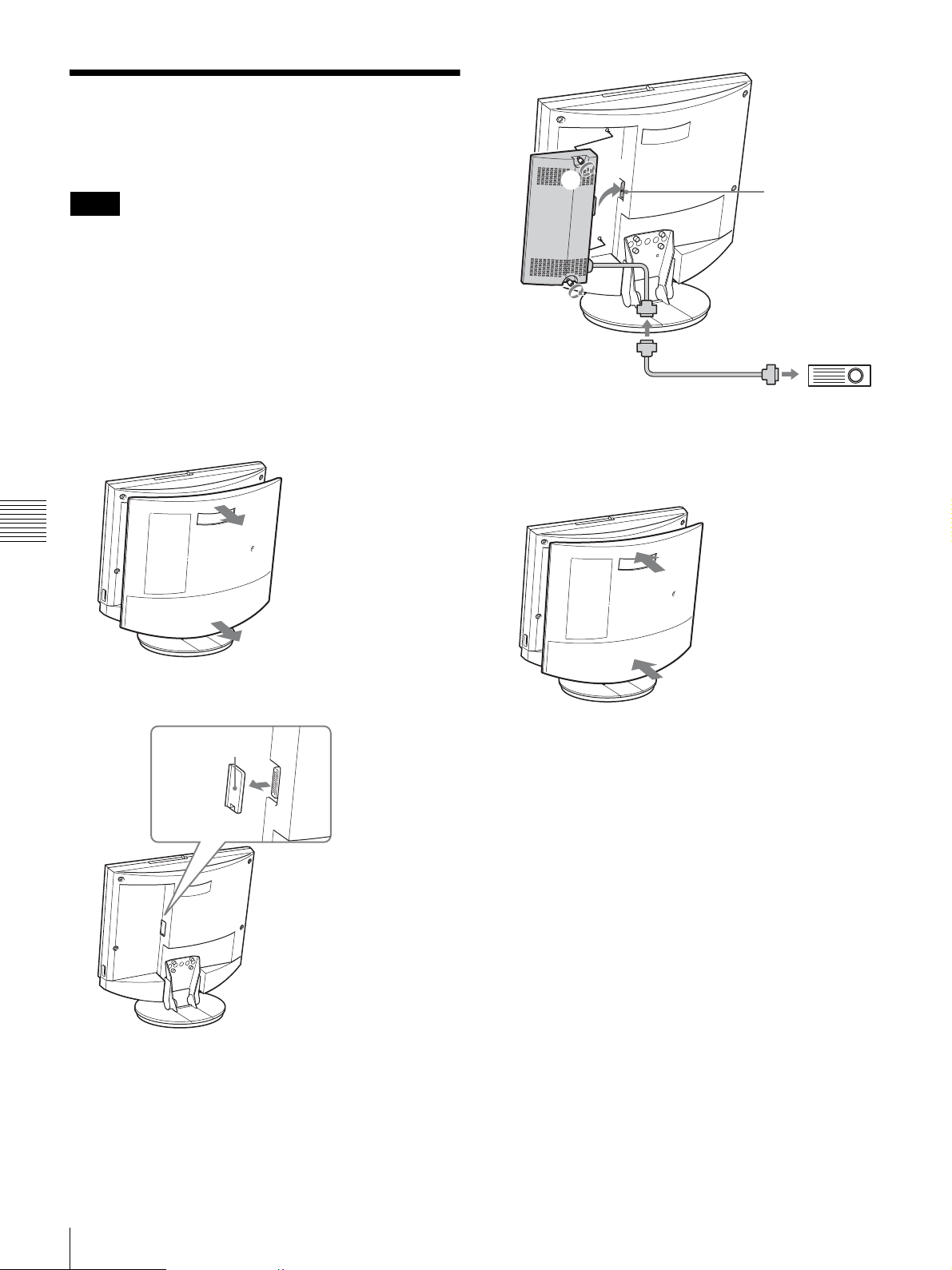
Installing the Dual Stream Box
Notes
• Be sure to turn the power to all components off before
starting the installation.
• When the Dual Stream Box has been connected and is
used for the first time, the Videoconferencing Terminal
may automatically upgrade the software of the Dual
Stream Box. While the upgrading message is displayed,
never turn off the Videoconferencing Terminal, to
prevent the possibility of serious system damage.
2
2
1
Connector
1
Remove the rear cover.
Pull the cover off towards you.
Chapter 5 Data Conference Using Dual Stream Box
2
Remove the DSB connector cover.
Connector cover
4
Replace the rear cover of the ViewPoint 8050.
Push the cover in while aligning the four stubs.
Mini D-sub 15-pin cable
(commercially available)
Projector or
similar
3
Connect the system connector of the Dual Stream Box
to the DSB connector of the ViewPoint 8050 and
secure with fastening screws.
76
Installing the Dual Stream Box
Page 79
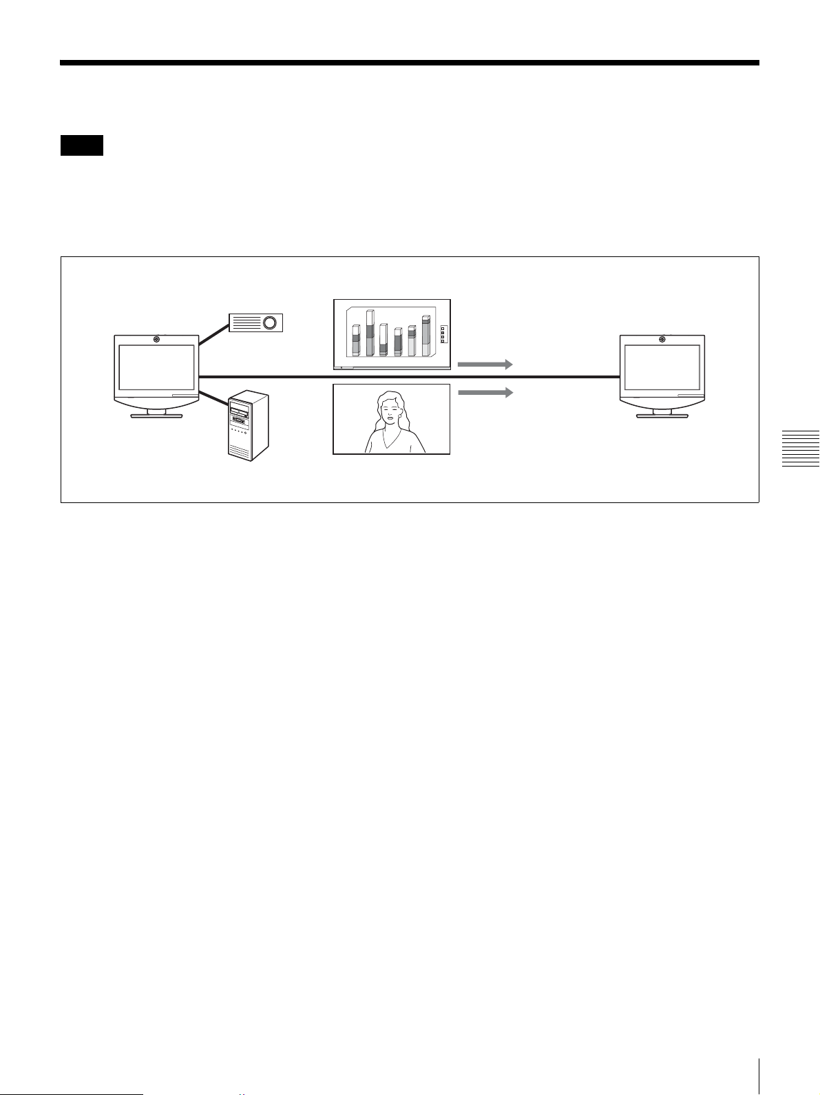
Connection Example Using the Dual Stream Box
Notes
• Before making any connections, be sure to turn power to
all components off.
• To prevent damage to the unit, do not connect or
disconnect any cable while power to the unit is turned
on.
1
8
0
0
6
1
0
4
1
0
2
Projector or similar
1
0
0
1
0
6
0
5
0
4
0
2
0
1
4
3
2
4
0
d
c
b
a
Computer image
6
5
Camera image
Chapter 5 Data Conference Using Dual Stream Box
Connection Example Using the Dual Stream Box
77
Page 80
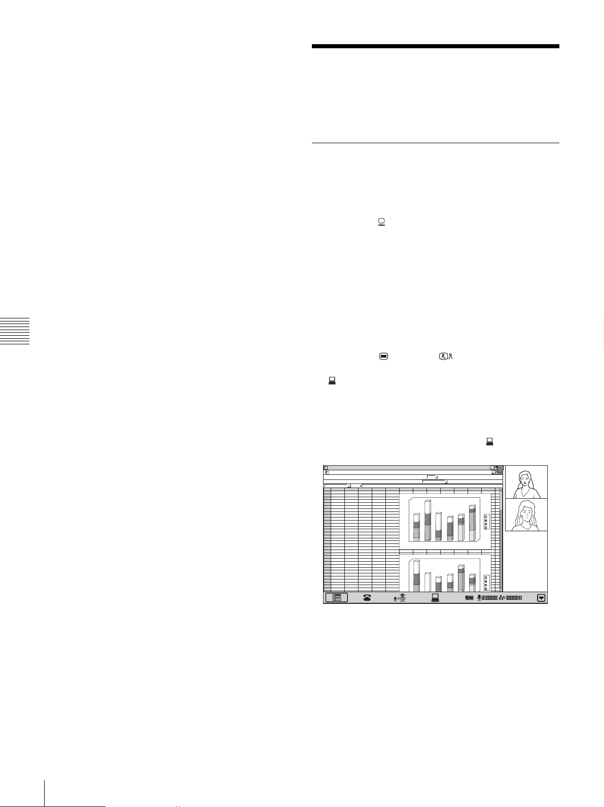
Notes on the connection example
Connecting a projector or similar to the RGB OUT
connector of the Dual Stream Box enables the following
features:
- Displaying the received computer picture with optimum
picture quality
- Transmitting the picture of a locally connected computer
to the remote party
Chapter 5 Data Conference Using Dual Stream Box
Using Video From Connected Equipment for a Conference
Operating the System During a Conference
To transmit a picture from a computer
First, press the (PC) button, and make sure that the
computer images input are displayed and that the Dual
Stream Box supports the RGB IN signals.
Be aware that although WXGA can be displayed on the
screen, it cannot be sent.
For details on acceptable RGB IN signals on the Dual
Stream Box, see “ViewPoint 8050-DSB Dual Stream Box
(RGB IN) (Connector located on ViewPoint 8050)” on
page 111.
Next, press the (Menu) or (Videoconference)
button to display the communication control bar, and click
the (Send) button.
The computer picture is displayed on a projector connected
to the RGB OUT connector and on the Videoconferencing
Terminal, and it is also transmitted to the remote party.
To stop the transmission, click the same (Stop) button.
ABCDEF GH I J KLMN
1
2
abc d
3
12
46
23
34
4
4
67
5
5
12
6
6
16
7
69
7
8
44
76
9
10
11
12
13
14
15
16
17
18
19
20
21
22
23
24
25
abc d
26
67
4
27
12
5
28
16
6
29
45
12
30
78
46
31
7
69
32
33
34
45
26
57
23
15
45
26
57
23
15
23
180
56
76
0
6
1
38
0
14
13
12
0
12
00
1
60
50
0
4
20
0
1
180
60
1
56
40
1
76
23
0
2
1
34
00
1
12
13
60
50
0
4
4
3
2
d
c
b
a
6
5
d
c
b
a
01:25
The computer picture displayed on a projector and on the
Videoconferencing Terminal is the image as input to the
Dual Stream Box. However, the image transmitted to the
remote party may be lacking in detail and may have
dropped frames.
78
Using Video From Connected Equipment for a Conference
For details on picture quality, see “Picture quality of the
Dual Stream Box” on page 79.
Page 81
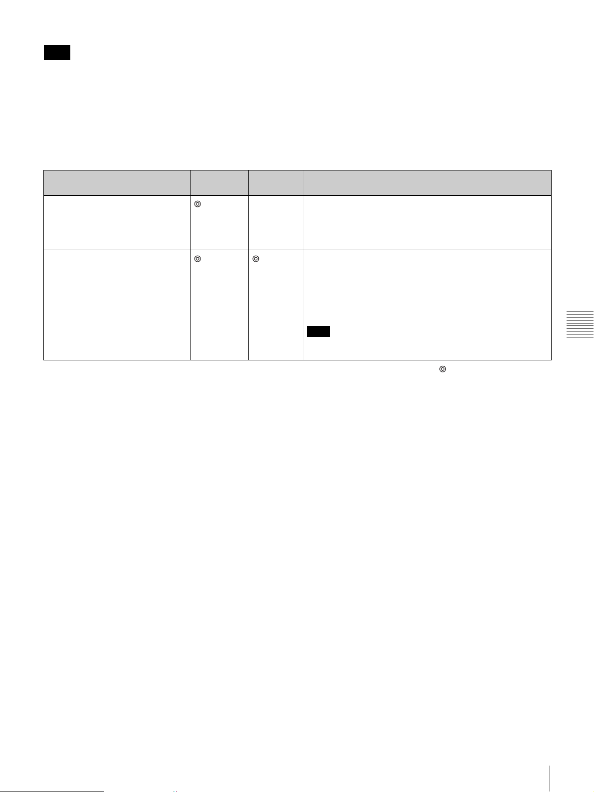
Note
While you are transmitting a computer picture, you cannot
receive a still image or a computer picture from any other
terminal. Ending your transmission enables you to receive
it. While you are receiving a still image or computer
picture from any other terminal, you cannot transmit a
computer picture.
Picture quality of the Dual Stream Box
The picture quality received by the remote party varies
depending on the type of terminal and connecting method,
and the “Monitor Out (or Sub Monitor Out)” settings at the
remote site. Using a Dual Stream Box also on the remote
site enables reception of a high-quality computer picture
with a higher frame rate.
When the ViewPoint 8050 is used as a receiving terminal
Dual Stream Box attached Resolution Video
frame rate
No (Display on the ViewPoint 8050)
Yes Outputs the signal by converting a transmitted VGA, SVGA or
a
Picture quality
Outputs the signal by converting a transmitted VGA, SVGA or
XGA signal into an XGA signal. The high-resolution picture
can be obtained. The number of frames displayed per
second depends on the interface transmission rate. For
example, one frame per second is obtained.
XGA signal into an XGA signal. The high-resolution picture
can be obtained. You can view a more vivid picture than the
picture output from the display on the Videoconferencing
Terminal. The number of frames displayed per second
depends on the interface transmission rates. For example,
five frames per second are obtained at 1 Mbps.
Note
Three frames per second are obtained for a transmitted XGA
signal.
: High, a: Middle, f: Low
Chapter 5 Data Conference Using Dual Stream Box
Using Video From Connected Equipment for a Conference
79
Page 82
Use as Computer Display
When you are not conducting a videoconference, you can
use the display of the Videoconferencing Terminal as a
computer display.
This chapter describes the use of the Videoconferencing
Terminal other than as a videoconference terminal.
Chapter 6
Chapter
6
Using as Computer Display
By connecting the Videoconferencing Terminal to a
computer, you can view the picture from a computer on the
display of the system.
Connecting to a Computer
Remove the rear cover of the Videoconferencing Terminal
and connect a computer.
For removing the rear cover, see page 20.
Use as Computer Display
When a computer is connected, you can either use a
separate mouse for the ViewPoint 8050 and the computer,
or you can link the ViewPoint 8050 and the computer
using a USB cable (commercially available) and control
both devices with the same mouse.
Note
Use a USB cable that is 3 m (10 ft.) or shorter.
80
Using as Computer Display
Page 83
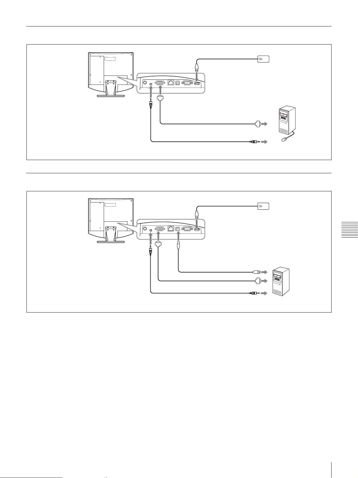
Separate Mouse
Videoconferencing
Terminal ViewPoint 8050
To mouse port
Optical mouse
ViewPoint 8050-MS
(supplied)
Shared Mouse
Videoconferencing
Terminal ViewPoint 8050
To AUDIO IN jack
To AUDIO
IN jack
To RGB IN connector
Cable with 15-pin mini
D-sub connector
(commercially available)
Audio cable with stereo mini plug
(commercially available)
To mouse port
To PC port
To RGB
IN
connector
USB cable (commercially
available) *
To RGB output
To audio output
To USB port
Computer
Optical mouse
ViewPoint 8050-MS
(supplied)
Chapter 6
Use as Computer Display
* Use a USB cable that is 3 m
(10 ft.) or shorter.
Cable with 15-pin mini D-sub
connector (commercially available)
Audio cable with stereo mini plug
(commercially available)
To RGB output
To audio output
Computer
Using as Computer Display
81
Page 84
Displaying the Picture From the Computer
1
Press the (PC) button on the ViewPoint 8050.
The display is switched to the computer screen.
When PC display is selected, the speakers of the
ViewPoint 8050 reproduce the sound from the
computer in stereo (if an audio connection has been
established).
2
Use the (Volume) buttons on the ViewPoint 8050
to adjust the volume of the computer sound.
3
Adjust the image quality.
For details on the adjustment, see “Display Setup
Menu” on page 39.
Displaying the Picture From the Computer During a Videoconference
To view the picture from the computer during
communication, press the (PC) button on the ViewPoint
8050. The system automatically enters Picture-in-Picture
mode, and the video from the remote party is displayed as
a window picture.
Chapter 6
To change the screen layout, press the (Menu) button on
the ViewPoint 8050 and bring up the setup menu bar.
For details on selecting the display mode, see “Switching
Use as Computer Display
the Display” on page 65.
82
Using as Computer Display
Page 85
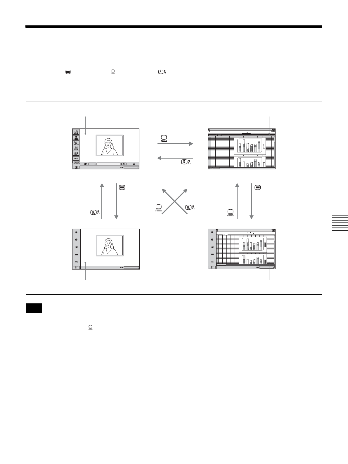
Switching Between Videoconference Display and Computer Display
You can use the (Menu) button, (PC) button, and
(Videoconference) button at the bottom right of the unit to
switch between the videoconference screen and computer
screen display.
Videoconference screen (launcher menu) Normal computer screen
ABCDEFGH IJ KLMN
1
abcd
2
3
23
34
46
IP
Click Icon to go into the function.
IP:
012.345.678.912
12
4
4
5
5
6
6
7
69
8
44
9
10
11
12
13
14
15
16
17
18
19
20
21
22
23
24
25
abcd
26
4
27
5
28
6
29
12
30
46
31
69
32
33
34
180
45
56
67
26
76
12
16
7
76
67
12
16
45
78
7
6
0
1
57
38
1
4
0
23
13
15
12
1
2
0
1
0
0
6
0
5
0
4
0
2
0
0
1
2
180
1
6
0
56
45
1
4
0
76
26
23
57
0
1
2
34
23
1
0
0
12
15
13
23
6
0
5
0
4
0
d
c
b
a
6
5
4
3
d
c
b
a
Click Icon to go into the function.
IP:
012.345.678.912
Videoconference screen (setup menu) Computer screen (setup menu)
Notes
• When the ViewPoint 8050 is not connected to a
computer, pressing the (PC) button to switch to
computer display will disable the mouse.
• If a sub-picture is being displayed during a
communication session, the sub-picture will remain
visible also when you switch to computer display.
However, the video shown on the sub-picture will be
either from the remote system or the local system.
• When separate mice are being used for the ViewPoint
8050 and for the computer, the currently active mouse
will depend on the current display screen. While the
normal computer screen is displayed, the mouse
connected to the computer is active. When other screens
are displayed, the mouse connected to the ViewPoint
8050 is active.
ABCDEFGH IJ KLMN
1
2
abcd
3
12
46
23
34
4
4
5
5
6
6
7
69
8
44
9
10
11
12
13
14
15
16
17
18
19
20
21
22
23
24
25
abcd
26
4
27
5
28
6
29
12
30
46
31
69
32
33
34
Click Icon to go into the function.
180
67
45
56
12
26
76
0
1
6
16
57
38
0
1
4
7
23
13
76
15
12
0
1
2
1
0
0
0
6
0
5
4
0
2
0
0
1
2
180
1
6
0
67
45
56
1
4
0
12
26
76
16
57
23
1
2
0
45
23
34
1
0
0
78
15
12
7
23
13
6
0
5
0
4
0
d
c
b
a
6
4
5
3
d
c
b
a
IP:
012.345.678.912
Chapter 6
Use as Computer Display
Switching Between Videoconference Display and Computer Display
83
Page 86
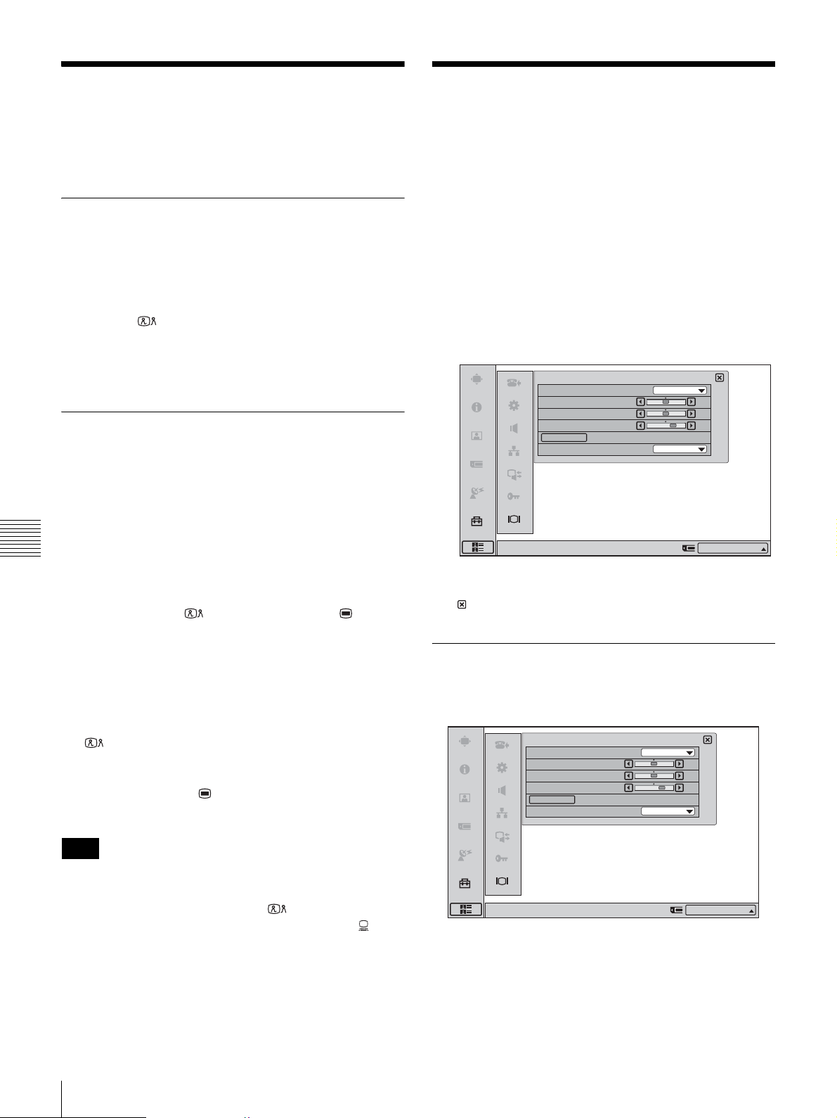
Calling a Remote Party or
Adjusting the Picture
Receiving a Call at the PC
Screen
Calling a Remote Party While PC Screen Is Shown
While a computer image is shown on the display of the
ViewPoint 8050, calling a remote party is not possible.
You must first switch to the videoconference screen by
pressing the (Videoconference) button on the unit.
For details on calling a remote party, see “Starting a
Conference by Calling a Remote Party” on page 52.
Receiving a Call While PC Screen Is Shown
When a call from a remote party is received, the procedure
differs depending on whether Auto Answer or Manual
Answer has been selected.
Quality on the Display
You can adjust the picture quality on the display in the
Display Setup menu.
The picture quality setting items differ depending on the
picture (main picture) currently on the display:
videoconference or picture from a computer. The adjusted
values are retained for each of the two picture types,
respectively.
1
Press “Display” in the screen to select the menu.
The Display Setup menu appears.
Display Setup (Videoconference)
Quality Mode
Picture
Brightness
Backlight
Reset
Wide Mode
Standard
50
50
70
Zoom
Auto Answer mode
Chapter 6
The system automatically receives the call from the remote
party and the videoconference begins.
However, screen display settings cannot be changed at the
PC screen. Press the (Videoconference) or (Menu)
Use as Computer Display
button on the unit to switch to the videoconference screen.
Manual mode
When there is an incoming call, a ringer tone sounds. You
need to connect the call manually to start the conference,
but this procedure is not possible at the PC screen. To
begin a conference, obey the message on the screen, press
the (Videoconference) button on the main unit, and
click “OK”. The display switches to the videoconference
screen.
You can also press the (Menu) button on the main unit
and click “OK” to begin a conference.
Note
When “Videoconference Button Answer” is set to “On” in
the Answer Setup menu and you receive a call, you can
start the conference by pressing the (Videoconference)
button on the unit or reject the call by pressing the (PC)
button.
Right-click the mouse to display a help message.
2
Make settings for the respective items, and then click
IP:012.345.678.912
.
Display Setup Menu for
Videoconference
Display Setup (Videoconference)
Quality Mode
Picture
Brightness
Backlight
Reset
Wide Mode
Right-click the mouse to display a help message.
Standard
50
50
70
Zoom
IP:012.345.678.912
84
Calling a Remote Party or Receiving a Call at the PC Screen / Adjusting the Picture Quality on the Display
Page 87
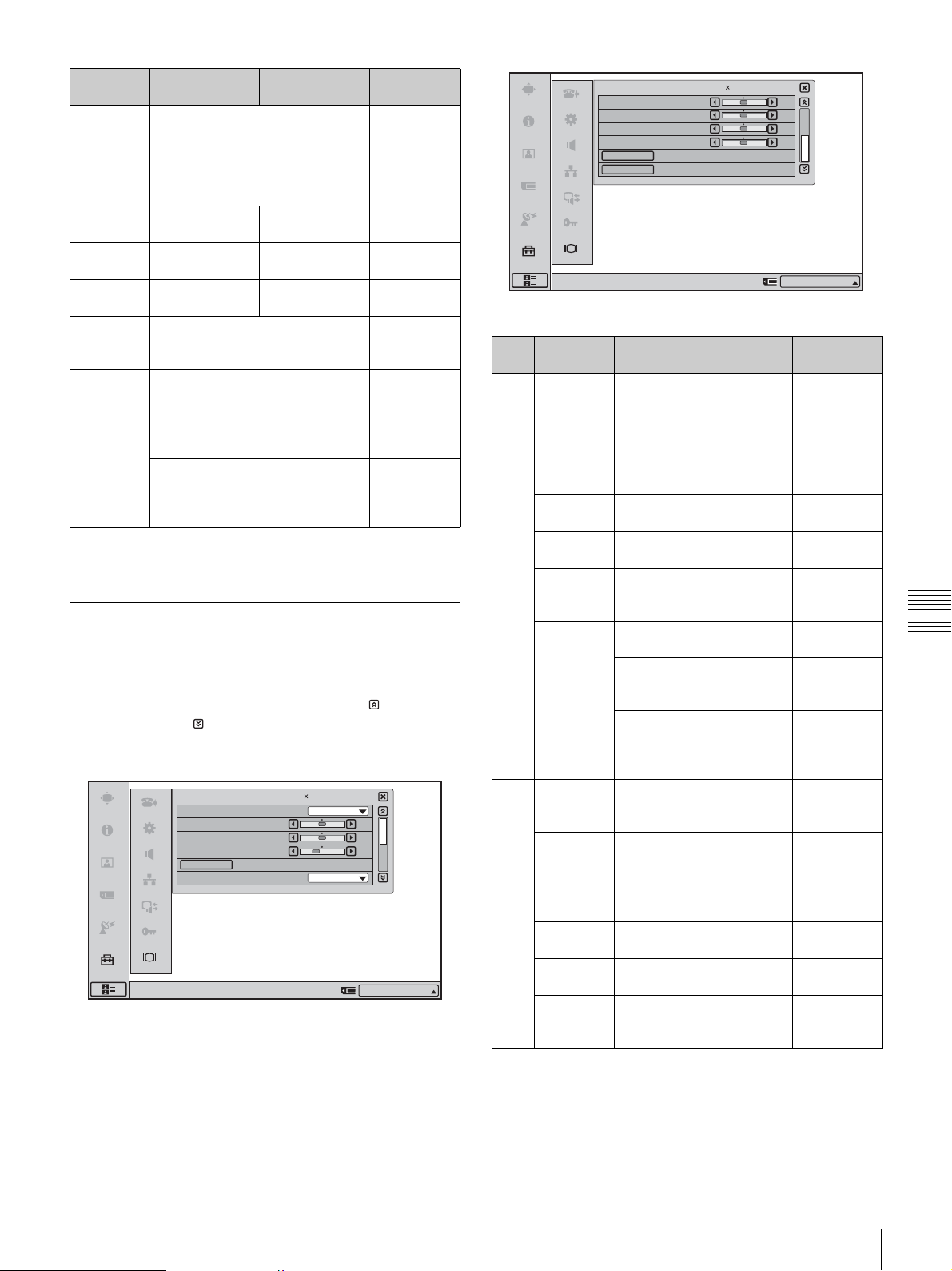
Setting
item
Quality
Mode
Press b to Press B to Adjustment
range
select “Vivid”, “Standard” or “Pro”
from the pull-down list.
“Vivid” for bluish tone, or “Pro” for
reddish tone. The “Standard”
–
setting is between “Vivid” and
“Pro”.
Picture decrease
picture contrast
Brightness darken the
picture
Backlight darken the
backlight
increase picture
contrast
brighten the
picture
brighten the
backlight
0 to 100
0 to 100
0 to 100
Reset Return Picture, Brightness, and
Backlight settings to default
–
values.
Wide
Mode*
Normal: The 4:3 picture is
displayed as it is.
–
Wide: The wide picture is created
by increasing the width of the 4:3
–
picture.
Zoom: The wide picture is
created by enlarging the 4:3
picture and cutting the upper and
–
lower parts.
* When Picture-and-Picture or Side-by-Side is selected for the screen
layout, the display does not change.
Display Setup Menu for the Computer Picture
The Display Setup menu for the computer picture consists
of two pages. To switch between tabs, click (return to
previous page) or (go to next page) at the right side of
the screen.
Display Setup (PC)
Quality Mode
Picture
Brightness
Backlight
Reset
Wide Mode
Right-click the mouse to display a help message.
1280 768/60Hz
Middle
Normal
1/2
50
50
40
IP:012.345.678.912
H Shift
V Shift
Phase
Pitch
Auto Adjust
Reset
Right-click the mouse to display a help message.
Page Setting
Press b to Press B to Adjustment
item
1/2 Quality
Mode
select the color
temperature of the display
from the pull-down list,
“High”, “Middle” or “Low”.
Picture decrease
picture
contrast
Brightness darken the
picture
Backlight darken the
backlight
Reset Return Picture, Brightness,
and Backlight settings to
default values.
Wide
Mode*
Normal: The 4:3 picture is
displayed as it is.
Wide: The wide picture is
created by increasing the
width of the 4:3 picture.
Zoom: The wide picture is
created by enlarging the
4:3 picture and cutting the
upper and lower parts.
2/2 H Shift shift the
picture to the
left
V Shift shift the
picture
downward
Phase reduce blur of horizontal
stripes and characters
Pitch eliminate vertical thick
stripes
AutoAdjust adjust the phase and pitch
automatically
Reset Return H Shift, V Shift,
Phase, and Pitch settings
to default values.
1280 768/60Hz
increase
picture
contrast
brighten the
picture
brighten the
backlight
shift the
picture to the
right
shift the
picture
upward
2/2Display Setup (PC)
50
50
50
50
IP:012.345.678.912
range
–
0 to 100
0 to 100
0 to 100
–
–
–
–
0 to 100**
0 to 100**
0 to 63
0 to 100
–
–
Chapter 6
Use as Computer Display
* When Picture-and-Picture or Side-by-Side is selected for the screen
layout, the display does not change.
**The adjustment range for H Shift and V Shift may differ depending on the
specifications of the input RGB signal.
Adjusting the Picture Quality on the Display
85
Page 88
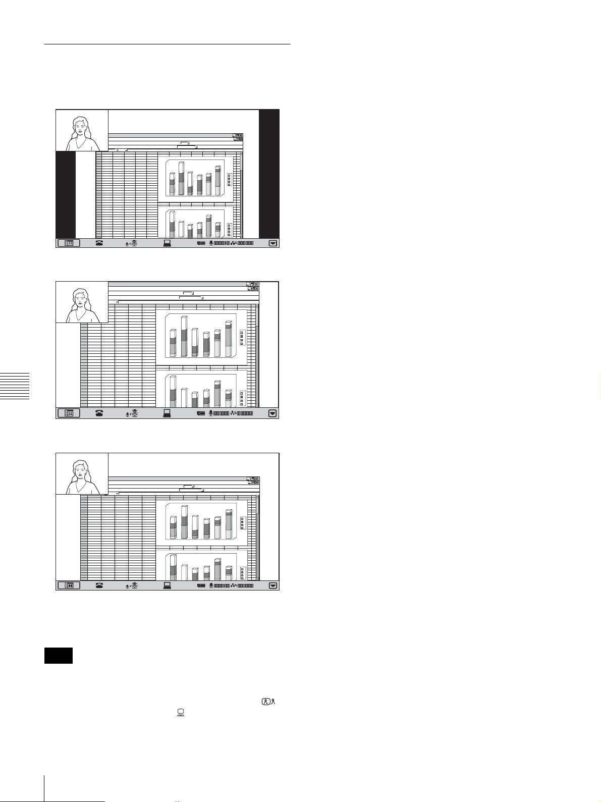
Differences in Wide Mode Settings
The “Wide Mode” item in the Display Setup menu
changes the display as follows.
ABCDEF GHI J KLMN
1
abc d
2
3
12
46
23
34
1
8
4
4
67
5
6
7
8
9
10
11
12
13
14
15
16
17
18
19
20
21
22
23
24
25
26
27
28
29
30
31
32
33
34
ABCDEF GH I J KLMN
1
abc d
2
3
12
4
4
5
5
6
6
7
69
8
44
9
10
11
12
13
14
15
16
17
18
19
20
21
22
23
24
25
abc d
26
4
27
5
28
6
29
12
30
46
31
69
Chapter 6
32
33
34
45
5
12
26
6
16
57
69
7
23
44
76
15
abc d
4
67
45
5
12
26
6
16
57
12
45
23
46
78
15
69
7
23
46
23
67
45
12
26
16
57
7
23
76
15
45
67
26
12
57
16
23
45
15
78
23
7
56
76
38
13
12
56
76
23
34
12
13
34
56
76
38
13
12
56
76
23
34
12
13
0
0
6
1
0
4
1
0
2
1
0
0
1
0
6
0
5
0
4
0
2
0
1
1
8
0
0
6
1
0
4
1
0
2
1
0
0
1
0
6
0
5
Normal
180
60
1
0
14
20
1
00
1
60
0
5
0
4
0
2
0
1
180
0
16
0
14
0
12
0
0
1
0
6
0
5
40
3
4
5
2
2
6
6
5
4
3
d
c
b
a
d
c
b
a
01:25
d
c
b
a
d
c
b
a
01:25
Zoom
Use as Computer Display
ABCDEF GHI J KLMN
1
abc d
2
3
12
46
23
34
1
8
4
4
67
5
5
12
6
6
16
7
69
7
8
44
76
9
10
11
12
13
14
15
16
17
18
19
20
21
22
23
24
25
abc d
26
4
67
27
5
12
28
6
16
29
12
45
30
46
78
31
69
7
32
33
34
45
26
57
23
15
45
26
57
23
15
23
0
56
76
0
6
1
38
0
4
1
13
12
0
2
1
0
0
1
0
6
0
5
0
4
0
2
0
3
1
1
8
0
0
6
1
56
0
4
1
76
23
0
2
1
34
0
0
1
12
13
0
6
0
5
0
4
4
5
2
6
Wide
To reset to the default picture quality
Click “Reset” button in the Display Setup menu.
Notes
• The setting items are different in videoconference mode
and PC (computer display) mode.
• When the display screen is switched by pressing
(Videoconference) button or (PC) button on the
Videoconferencing Terminal, the Display Setup menu
disappears.
d
c
b
a
d
c
b
a
01:25
86
Adjusting the Picture Quality on the Display
Page 89

Web Control Function
This chapter introduces the Web Control Function which
is used to operate the ViewPoint 8050 over a LAN. The
Web Control Function helps you control the ViewPoint
8050, or change its setup configuration, using a Web
browser installed on your PC, such as Internet Explorer.
The following is a set of Operating Instructions for the
Web Control Function.
Internet Explorer is a product of the Microsoft
Corporation. Please use Version 5.0, or above (Version 6.0
recommended).
Chapter
7
Open the Web Page
Enter the IP address assigned to the ViewPoint 8050 in the
address line of your browser.
The format of an address is:
http://XXX.XXX.XXX.XXX/
For instance, if the IP address is “192.168.1.24”, enter
“http://192.168.1.24/” in the address line.
Notes
• When a proxy server in an external network segment has
been set, the Gateway address in the ViewPoint 8050
LAN setting must also be set. Or set your Web browser
proxy setting to “No Proxy” for the ViewPoint 8050.
• The window that appears after logging in uses your Web
browser’s pop-up function. If you are using your
browser’s pop-up blocker function, make sure to disable
it.
Chapter 7 Web Control Function
Open the Web Page
87
Page 90
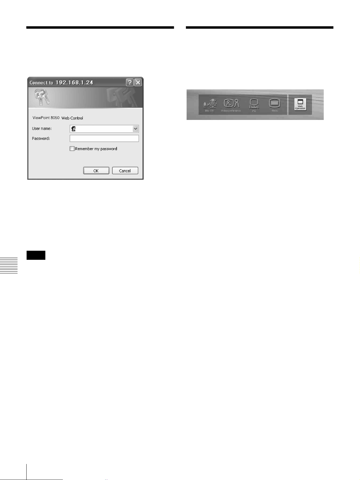
Identify a User
Once you reach the Web page, the following window will
be displayed asking you to identify yourself as the user.
Enter one of the following user names (see below) into the
“User Name” box and the corresponding password into the
“Password” box, then click the [OK] button.
Each character of a password is shown as “*” on the
screen. When the user name and password are correct, the
menu box will come up. If an incorrect user name or
password is entered three times, an error message appears
on the screen.
How To Use the “Web Control” Window
After logging in successfully, the “ViewPoint 8050 Web
Control” window appears.
Clicking the [Mic Off], [Videoconference], [PC], and
[Menu] buttons in the window have the same effect as
pressing the respective buttons on the actual unit.
When you click the [Web Operation] button, the Dial/
Disconnect page appears.
Notes
• When you enter “user” in the “User Name” box and then
Chapter 7 Web Control Function
its password (Remote Access Password) in the
“Password” box, you can access and check the “Phone
Book” and “Setup” pages.
• When you enter “super” in the “User Name” box and
then its password (Phone Book Modification Password)
in the “Password” box, you can access the “Phone Book”
page, change the setting of the page, and register a new
entry onto the page. And you can check the “Setup”
page.
• When you enter “VP8050” in the “User Name” box and
then its password (Administrator Password) in the
“Password” box, you can access the “Phone Book” page,
change the setting of the page, and register a new entry
onto the page. And you can check and modify the
“Setup” page.
• If the corresponding password is not assigned, leave the
“Password” box blank and click the [OK] button.
• Administrator Setup Password, Phone Book
Modification Password and Remote Access Password
settings are in the Administrator Setup menu.
88
Identify a User / How To Use the “Web Control” Window
Page 91

Select a Tool
By clicking a tool button on the top part of the page, you
can jump to the corresponding tool page. A brief
introduction of each tool is presented below.
[Controller]
Controls the ViewPoint 8050 using the on-screen
controller.
[Dial/Disconnect]
Calls a remote party, or ends a meeting.
[Phone Book]
Displays the dial list.
Connects from the dial list.
Registers, confirms or edits the dial list.
For a private address book, the “Phone Book”
button changes to the “Private Phone Book”
button.
[Setup]
Confirms or modifies the setup.
Sends messages.
Resets the setup functions (only when “VP8050” has been
entered as the user name).
[Status & Info]
Displays the connection status, line status, or other
machine information.
Displays the “Cause Code.”
Displays the “Call Log” (only when “VP8050” has been
entered as the user name).
[Monitor]
Allows you to monitor images from the ViewPoint 8050.
Note
When “Web Monitor” in the Administrator Setup menu is
set to “Off”, you cannot monitor the images.
Chapter 7 Web Control Function
Select a Tool
89
Page 92
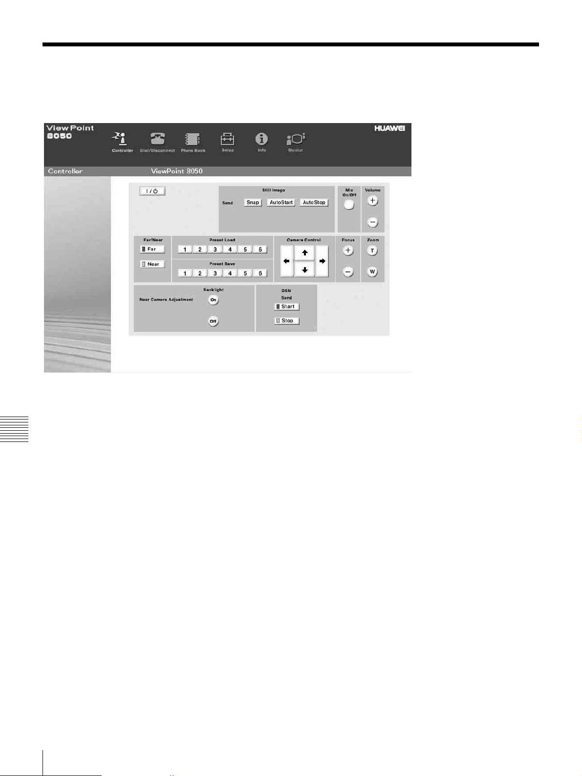
How To Use “Controller”
To control the ViewPoint 8050 from the on-screen
controller
When you click the [Controller] button, the on-screen
control panel appears. By clicking the buttons on this
control panel, you can control the ViewPoint 8050,
sending still images, operating the camera, registering
preset camera settings, and so on.
Chapter 7 Web Control Function
For example, in order to preset and load a camera setting:
a Set the camera at the desired position using the
Camera Control buttons.
b Click one of the “Preset Save” 1 to 6 buttons on the
image.
c The preset is done.
d Click one of the “Preset Load” 1 to 6 buttons on the
image to load it.
90
How To Use “Controller”
Page 93
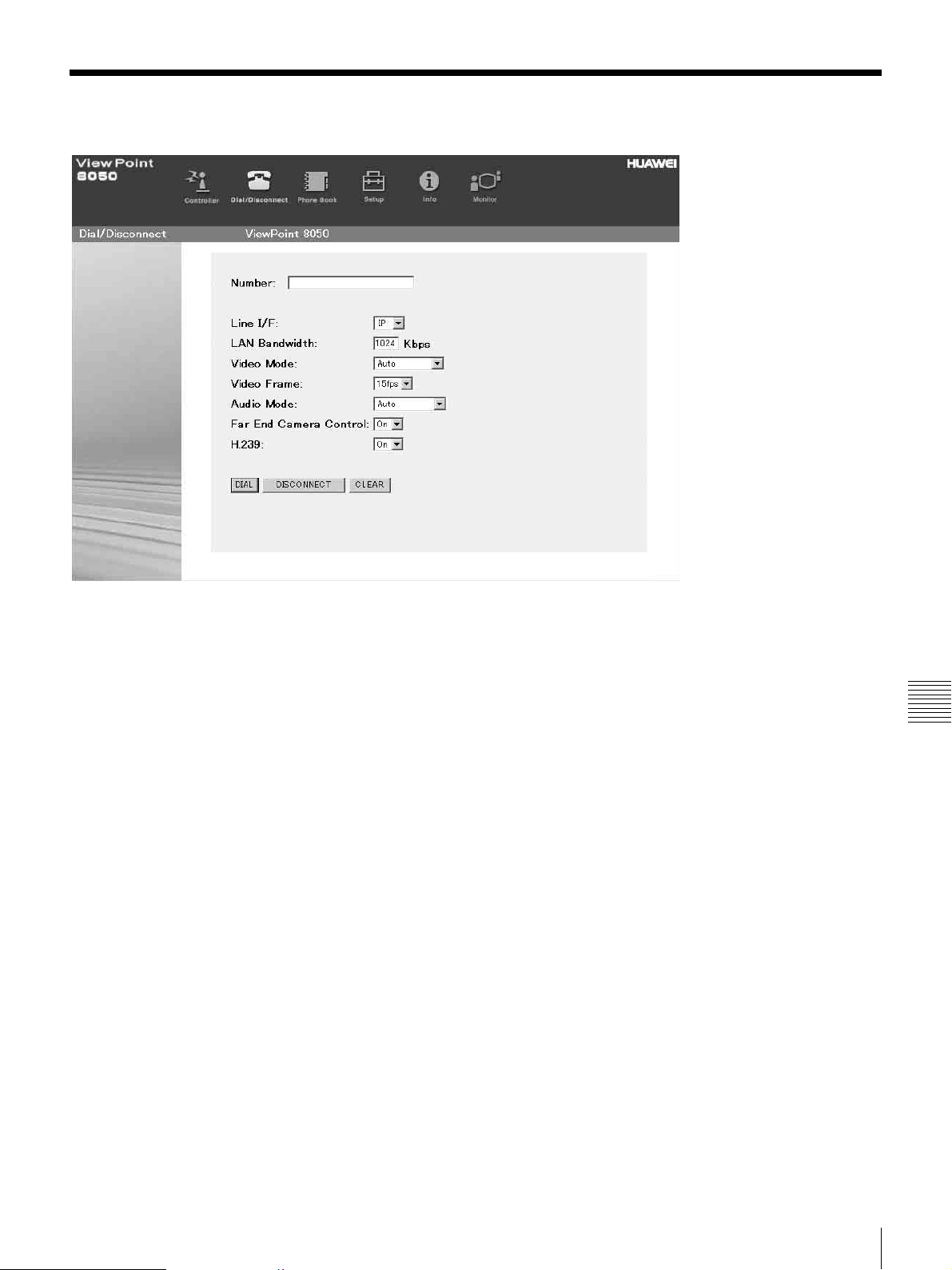
How To Use “Dial/Disconnect”
By clicking the [Dial/Disconnect] button, you can jump to
the “Dial/Disconnect” page.
To connect:
a Enter the telephone number(s) of a remote party
into the box(es): A1 (to C2) (When using a LAN,
enter an IP address or a DNS name.)
b Select the Line I/F, and configure any other
necessary setting items.
c Click the [DIAL] button.
d The message, “Now dialing...” appears.
e After the connection is made, the message,
“Connect OK.” will appear, and the screen will
return to the “Dial/Disconnect” page.
To disconnect:
a Click the [DISCONNECT] button.
b The message, “Now disconnecting...” appears.
To clear the dial number:
a Click the [CLEAR] button.
b The number(s) entered on this menu will be cleared
and the screen will return to the “Dial/Disconnect”
page.
Chapter 7 Web Control Function
c After the disconnection is completed, the message
“Disconnect OK.” will appear, and the screen will
return to the “Dial/Disconnect” page.
How To Use “Dial/Disconnect”
91
Page 94
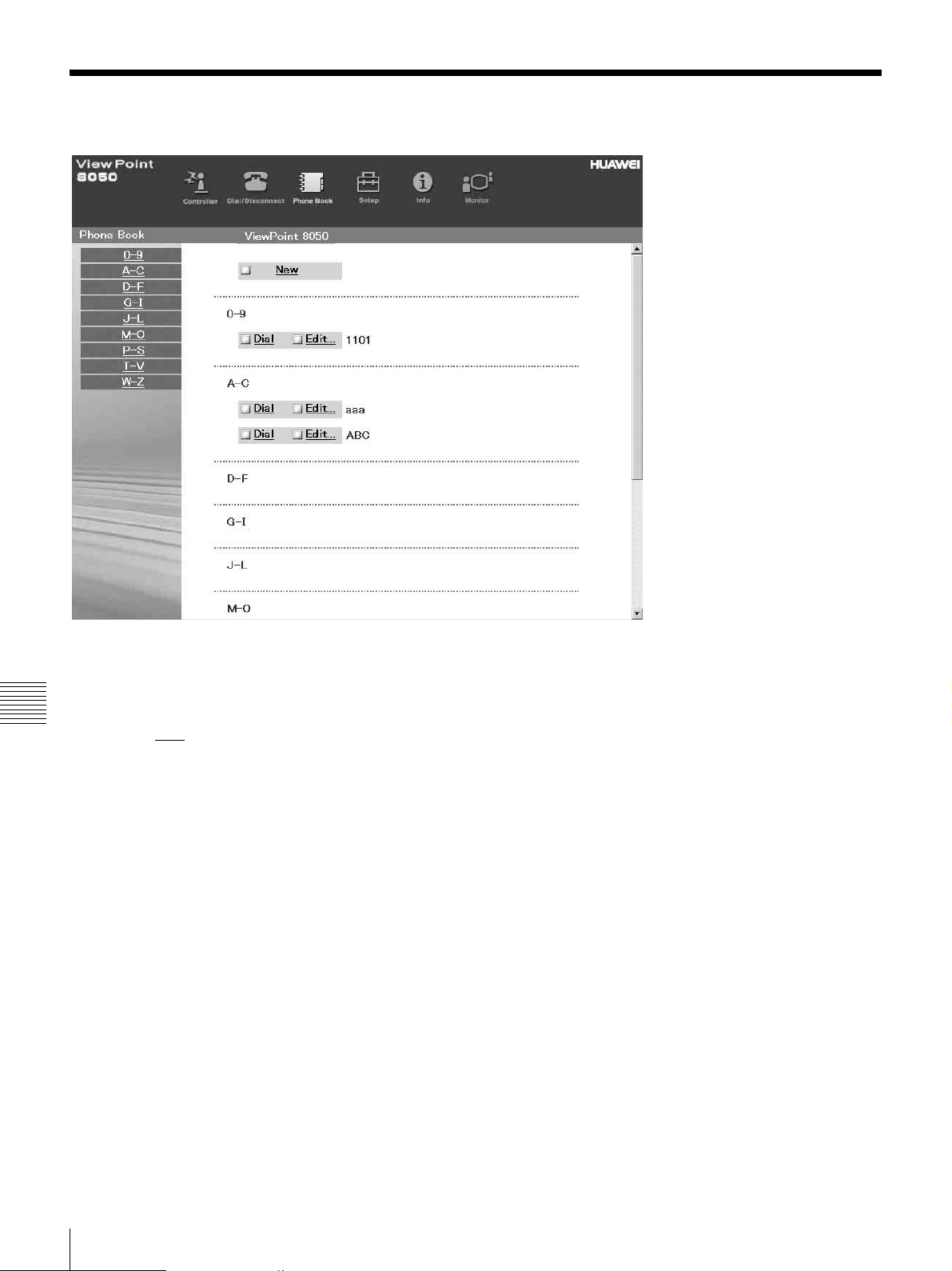
How To Use “Phone Book”
By clicking the [Phone Book] button, you can jump to the
“Phone Book list” page.
To connect:
Chapter 7 Web Control Function
a Click sDial
dialing.
Then, the message, “Now dialing...” will appear.
b After the connection is made, you will see the
message, “Connect OK.,” and the screen will
return to the list page.
next to the index title that you are
92
How To Use “Phone Book”
Page 95
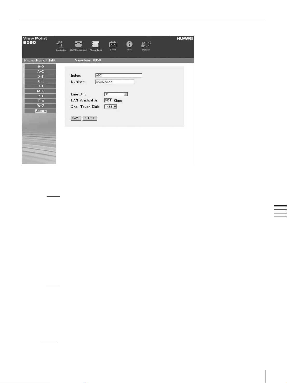
“Phone Book-Edit” Page
To edit the communication attribute (only when
“super” or “VP8050” has been entered as the
user name):
a Click sEdit...
communication attribute you want to edit or
modify on the list page.
Then, the “Phone Book-Edit” page will appear.
b Edit or modify the telephone numbers and
attributes.
c Click the [SAVE] button.
After saving the changes, the screen will return to the
list page.
To delete data from the Phone Book (only when
“super” or “VP8050” has been entered as the
user name):
a Click sEdit...
want to delete on the list page.
Then, the “Phone Book-Edit” page will appear.
b Click the [DELETE] button.
After the deletion is complete, the list page will
appear.
next to the index title whose
next to the index title whose data you
Chapter 7 Web Control Function
To return to the list page:
a Click Return
The list page will appear.
on the left part of the page.
How To Use “Phone Book”
93
Page 96
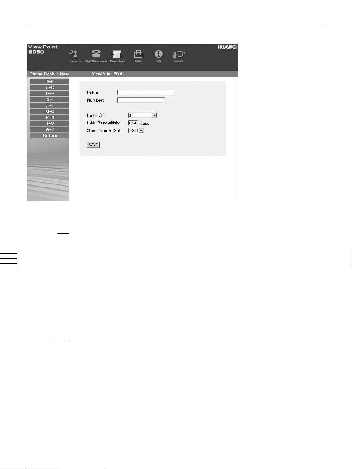
“Phone Book-New” Page
To register a new point (only when “super” or
“VP8050” has been entered as the user name):
a Click sNew
The “Phone Book-New” page will appear.
b Enter an index title into the Index box and
Chapter 7 Web Control Function
telephone numbers into box(es) A1 (to C2).
c Select the Line I/F, and configure any other
necessary setting items.
d Click the [SAVE] button.
After the registration is complete, the new index will
be added, and the screen will return to the list page.
To return to the list page:
a Click Return
The list page will appear.
on the list page.
on the left part of the page.
94
How To Use “Phone Book”
Page 97
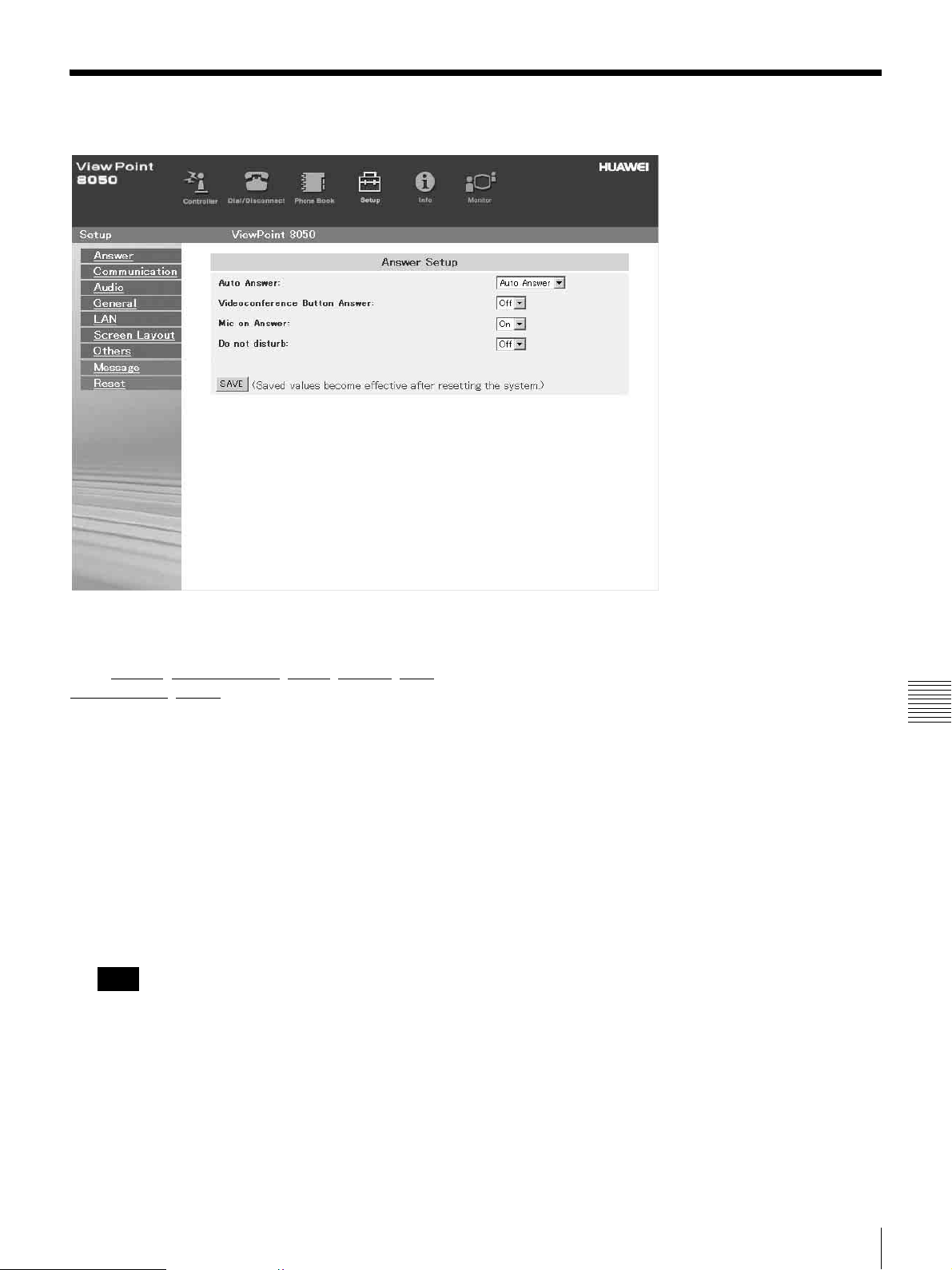
How To Use “Setup”
Click the [Setup] button, and you will jump to the
“Answer” page.
Click Answer
Screen Layout
according to what you are setting up.
To modify the attribute (only when “VP8050” has
been entered as the user name):
a Open the page whose attributes you want to
modify.
b Modify the attributes.
c Click the [SAVE] button.
After the modification is complete, the screen will
return to the same page as you see in step a.
Note
Sometimes the screen may not go back to the previous
page after modifying the “LAN” page. This is not a
malfunction.
, Communication, Audio, General, LAN,
, Others on the left part of the screen,
Chapter 7 Web Control Function
How To Use “Setup”
95
Page 98
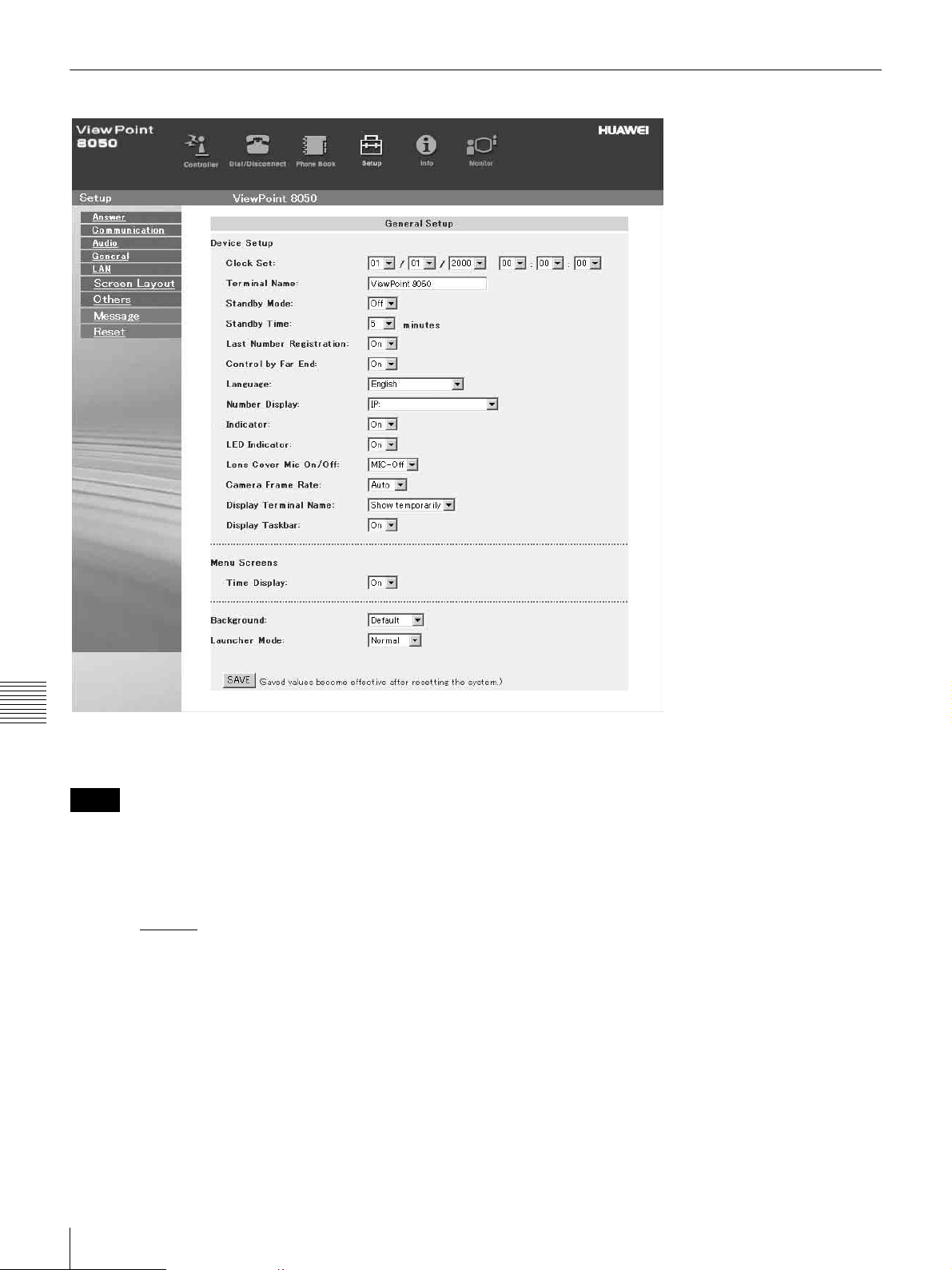
How To Configure KIOSK Mode
Chapter 7 Web Control Function
You can select the background of the launcher and select
the launcher mode.
Notes
• The KIOSK Mode setting can only be configured using
the Web Control Function.
• For detailed information on the KIOSK Mode setting,
consult your HUAWEI dealer.
a Click General
on the left side of the page.
The “General Setup” page will appear.
(You can only configure this setting when “VP8050”
has been entered as the user name.)
b Configure the “Background” and “Launcher
Mode” settings.
c Click the [SAVE] button.
After saving, the screen will return to the “General
Setup” page.
96
How To Use “Setup”
Page 99
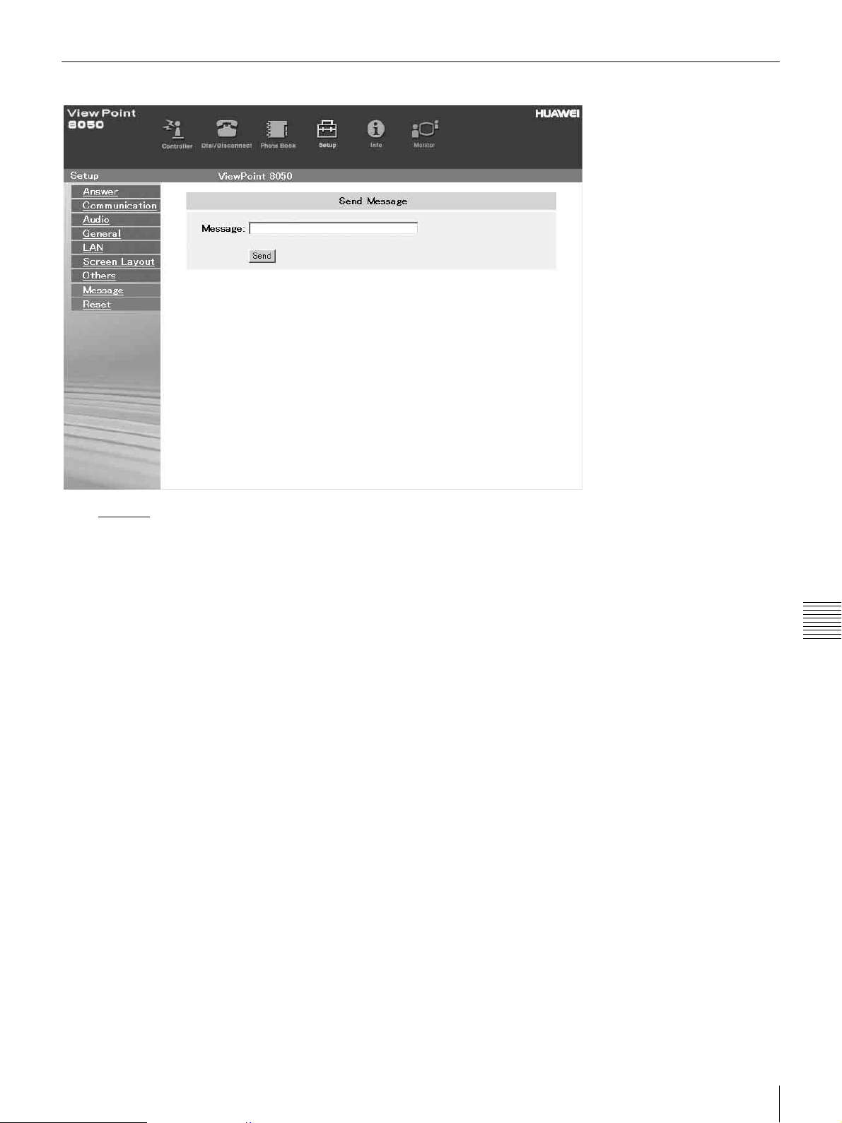
To Display the “Send Message” Page
Click Message on the left side of the page.
The “Send Message” page will appear.
Enter the message you want to send into the Message box
and click the [Send] button to send the message to the
ViewPoint 8050.
After the message is sent, “message send OK.” will be
displayed and the screen will return to the “Send Message”
page.
Chapter 7 Web Control Function
How To Use “Setup”
97
Page 100
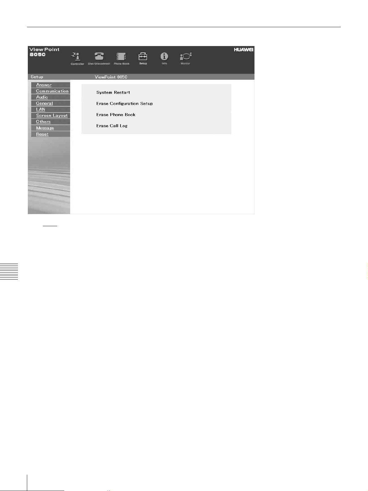
To Reset the System
Click Reset on the left part of the page. The “Reset” page
will appear (only when “VP8050” has been entered as the
user name).
a Click on the desired item.
A dialog box will appear.
Chapter 7 Web Control Function
b Click the [OK] button.
“System Restart”
Resets the ViewPoint 8050 system.
“Erase Configuration Setup”
Returns to the factory setting values.
“Erase Phone Book”
Erases all information saved in the “Phone Book.”
“Erase Call Log”
Erases all information saved in the “Call Log.”
98
How To Use “Setup”
 Loading...