

Page 1

UPS5000-A-30 kVA & 40 kVA & 80 kVA
User Manual
Issue
11
Date
2018-12-10
HUAWEI TECHNOLOGIES CO., LTD.
Page 2

Issue 11 (2018-12-10)
Copyright © Huawei Technologies Co., Ltd.
i
Copyright © Huawei Technologies Co., Ltd. 2018. All rights reserved.
No part of this document may be reproduced or transmitted in any form or by any means without prior
written consent of Huawei Technologies Co., Ltd.
Trademarks and Permissions
and other Huawei trademarks are trademarks of Huawei Technologies Co., Ltd.
All other trademarks and trade names mentioned in this document are the property of their respective
holders.
Notice
The purchased products, services and features are stipulated by the contract made between Huawei and
the customer. All or part of the products, services and features described in this document may not be
within the purchase scope or the usage scope. Unless otherwise specified in the contract, all statements,
information, and recommendations in this document are provided "AS IS" without warranties, guarantees or
representations of any kind, either express or implied.
The information in this document is subject to change without notice. Every effort has been made in the
preparation of this document to ensure accuracy of the contents, but all statements, information, and
recommendations in this document do not constitute a warranty of any kind, express or implied.
Huawei Technologies Co., Ltd.
Address:
Huawei Industrial Base
Bantian, Longgang
Shenzhen 518129
People's Republic of China
Website:
http://e.huawei.com
Page 3
UPS5000-A-30 kVA & 40 kVA & 80 kVA
User Manual
About This Document
Issue 11 (2018-12-10)
Copyright © Huawei Technologies Co., Ltd.
ii
Purpose
Symbol
Description
Indicates an imminently hazardous situation which, if
not avoided, will result in death or serious injury.
Indicates a potentially hazardous situation which, if not
avoided, could result in death or serious injury.
Indicates a potentially hazardous situation which, if not
avoided, may result in minor or moderate injury.
This document describes the high-frequency tower-mounted UPS5000-A-30 kVA & 40 kVA
& 80 kVA in terms of features, appearance, structure, working principle, technical
specifications, installation, operation, and maintenance. UPS is short for uninterruptible
power system. Unless otherwise specified, UPS refers to all the models described in this
document.
Intended Audience
About This Document
This document is intended for:
Sales engineers
Technical support engineers
System engineers
Hardware installation engineers
Commissioning engineers
Data configuration engineers
Maintenance engineers
Symbol Conventions
The symbols that may be found in this document are defined as follows.
Page 4
UPS5000-A-30 kVA & 40 kVA & 80 kVA
User Manual
About This Document
Issue 11 (2018-12-10)
Copyright © Huawei Technologies Co., Ltd.
iii
Symbol
Description
Indicates a potentially hazardous situation which, if not
avoided, could result in equipment damage, data loss,
performance deterioration, or unanticipated results.
NOTICE is used to address practices not related to
personal injury.
Calls attention to important information, best practices
and tips.
NOTE is used to address information not related to
personal injury, equipment damage, and environment
deterioration.
Change History
Changes between document issues are cumulative. The latest document issue contains all the
changes made in earlier issues.
Issue 11(2018-12-10)
Update some MDU screenshots.
Issue 10 (2018-04-18)
This issue is the tenth official release, which incorporates the following change:
Updated the model specifications.
Issue 09 (2018-01-03)
This issue is the ninth official release, which incorporates the following changes:
Updated the output electrical specifications and typical configuration.
Updated the Monitoring screen image.
Issue 08 (2017-06-09)
This issue is the eighth official release, which incorporates the following changes:
Updated the Monitoring screen image.
Issue 07 (2016-12-03)
This issue is the seventh official release, which incorporates the following changes:
Updated the UPS front space reservation in section 3.1.1 "Site".
Added the section 3.2.7.1 "UPS Cable Connection Reference".
Added checking for foreign matters in section 3.4 "Installation Verification".
Added the section 5.1.5 "Setting ECO Mode" and the section 5.1.6 "Testing Batteries".
Page 5

UPS5000-A-30 kVA & 40 kVA & 80 kVA
User Manual
About This Document
Issue 11 (2018-12-10)
Copyright © Huawei Technologies Co., Ltd.
iv
Updated the section 6 "Routine Maintenance".
Added the specifications of the internal circuit breaker in the section 8 "Technical
Specifications".
Issue 06 (2015-06-26)
This issue is the sixth official release, which incorporates the following changes:
Updated the Monitoring screen image.
Issue 05 (2014-09-26)
This issue is the fifth official release, which incorporates the following changes:
Added the features of four parallel systems and the battery monitoring unit (BMU).
Issue 04 (2014-07-16)
This issue is the fourth official release, which incorporates the following changes:
Updated section 1 Precautions.
Issue 03 (2014-01-20)
This issue is the third official release, which incorporates the following changes:
Updated section 1 Precautions.
Updated the secured installation for the UPS5000-A-60 kVA/80 kVA/120 kVA in section
3.2.2.
Updated section 7 Troubleshooting Alarm List.
Issue 02 (2013-11-18)
This is the second official release, which incorporates the following changes:
Added figures of OT and DT terminals for the UPS5000-A and tables that list their
specifications in section 3.1.3.
Issue 01(2013-11-05)
This is the first release.
Page 6

UPS5000-A-30 kVA & 40 kVA & 80 kVA
User Manual
Contents
Issue 11 (2018-12-10)
Copyright © Huawei Technologies Co., Ltd.
v
Contents
About This Document .................................................................................................................... ii
1 Safety Precautions ......................................................................................................................... 1
1.1 General Safety .............................................................................................................................................................. 1
1.2 Electrical Safety ............................................................................................................................................................ 3
1.3 Operating Environment................................................................................................................................................. 6
1.4 Battery Safety ............................................................................................................................................................... 6
1.5 Mechanical Safety ........................................................................................................................................................ 8
1.6 Laying Out Cables ........................................................................................................................................................ 9
1.7 Information About Foreign Objects near UPS Equipment Installation ....................................................................... 10
2 Overview ....................................................................................................................................... 12
2.1 Model Description ...................................................................................................................................................... 12
2.2 Working Principles...................................................................................................................................................... 12
2.2.1 Conceptual Diagram ................................................................................................................................................ 12
2.2.2 Working Modes ........................................................................................................................................................ 13
2.2.2.1 Normal Mode ........................................................................................................................................................ 13
2.2.2.2 Bypass Mode ........................................................................................................................................................ 14
2.2.2.3 Battery Mode ........................................................................................................................................................ 14
2.2.2.4 Maintenance Bypass Mode ................................................................................................................................... 15
2.2.2.5 ECO Mode ............................................................................................................................................................ 15
2.3 Product Description .................................................................................................................................................... 17
2.3.1 Appearance .............................................................................................................................................................. 17
2.3.2 Product Structure ..................................................................................................................................................... 18
2.3.2.1 30 kVA/40 kVA UPS ............................................................................................................................................. 18
2.3.2.2 80kVA UPS ................................ ................................................................ ........................................................... 22
2.3.3 Control Port ............................................................................................................................................................. 23
2.4 Typical configurations ................................................................................................................................................ 27
2.4.1 Single UPS ............................................................................................................................................................... 28
2.4.2 Parallel System ........................................................................................................................................................ 28
2.4.3 Dual-Bus System ..................................................................................................................................................... 29
2.5 Optional Components ................................................................................................................................................. 30
3 Installation.................................................................................................................................... 32
3.1 Installation Preparations ............................................................................................................................................. 32
Page 7

UPS5000-A-30 kVA & 40 kVA & 80 kVA
User Manual
Contents
Issue 11 (2018-12-10)
Copyright © Huawei Technologies Co., Ltd.
vi
3.1.1 Site ........................................................................................................................................................................... 32
3.1.2 Tools and Instruments .............................................................................................................................................. 35
3.1.3 Power Cables ........................................................................................................................................................... 37
3.1.4 Unpacking and Checking ......................................................................................................................................... 42
3.1.4.1 30 kVA/40 kVA UPS ............................................................................................................................................. 43
3.1.4.2 80 kVA UPS .......................................................................................................................................................... 44
3.2 Installing a Single UPS ............................................................................................................................................... 48
3.2.1 Installing the UPS5000-A-30 kVA/40 kVA ............................................................................................................. 48
3.2.2 Installing the UPS5000-A-80 kVA .......................................................................................................................... 59
3.2.3 (Optional) Installing Antiseismic Kits ..................................................................................................................... 71
3.2.4 (Optional) Installing a Battery Monitoring Unit ...................................................................................................... 72
3.2.5 Installing Batteries ................................................................................................................................................... 74
3.2.6 UPS Cable Connection Reference ........................................................................................................................... 75
3.2.7 Routing Cables......................................................................................................................................................... 76
3.2.7.1 Cable Routes ......................................................................................................................................................... 76
3.2.7.2 Connecting Ground Cables ................................................................................................................................... 78
3.2.7.3 Connecting AC Input Power Cables ..................................................................................................................... 80
3.2.7.4 Connecting AC Output Power Cables ................................................................................................................... 84
3.2.7.5 Connecting Battery Cables ................................................................................................................................... 85
3.2.8 Remote EPO ............................................................................................................................................................ 87
3.2.9 Connecting Communications Cables ....................................................................................................................... 88
3.3 Installing a Parallel System ......................................................................................................................................... 88
3.3.1 Connecting Power Cables ........................................................................................................................................ 88
3.3.2 Connecting Signal Cables ........................................................................................................................................ 92
3.4 Installation Verification ............................................................................................................................................... 94
4 LCD and WebUI .......................................................................................................................... 99
4.1 MDU ........................................................................................................................................................................... 99
4.2 LCD ................................................................ ................................ ................................................................ .......... 101
4.2.1 Overview ............................................................................................................................................................... 101
4.2.2 Status Screen .......................................................................................................................................................... 102
4.2.3 Alarms .................................................................................................................................................................... 105
4.2.4 Settings Screen....................................................................................................................................................... 106
4.2.5 Control ................................................................................................................................................................... 120
4.2.6 About Screen .......................................................................................................................................................... 122
4.3 WebUI ....................................................................................................................................................................... 122
4.3.1 Login ...................................................................................................................................................................... 122
4.3.2 Monitoring Page .................................................................................................................................................... 124
4.3.2.1 Parameter Settings .............................................................................................................................................. 125
4.3.2.2 Communications Settings ................................................................................................................................... 132
4.3.2.3 Control ................................................................................................................................................................ 132
4.3.3 Query Page ............................................................................................................................................................ 133
Page 8

UPS5000-A-30 kVA & 40 kVA & 80 kVA
User Manual
Contents
Issue 11 (2018-12-10)
Copyright © Huawei Technologies Co., Ltd.
vii
4.3.3.1 Historical Alarms Page ....................................................................................................................................... 133
4.3.3.2 Logs Page ........................................................................................................................................................... 133
4.3.4 Config. Page .......................................................................................................................................................... 134
4.3.4.1 User Management ............................................................................................................................................... 134
4.3.4.2 Site Config. ......................................................................................................................................................... 134
4.3.4.3 RCCMD .............................................................................................................................................................. 136
4.3.4.4 Managing the UPS by Using the NMS Complying with RFC1628 Standard ..................................................... 145
4.3.5 Protecting the Server by Using the RCCMD Software .......................................................................................... 146
4.3.5.1 Introduction to the Software ............................................................................................................................... 146
4.3.5.2 RCCMD Event Shutdown and Message Sending ............................................................................................... 147
4.3.5.3 UPS Alive Check Function ................................................................................................................................. 148
5 Operations .................................................................................................................................. 151
5.1 Powering On and Starting the UPS ........................................................................................................................... 151
5.2 Shutting Down and Powering Off the UPS .............................................................................................................. 155
5.3 Starting the UPS in Battery Mode ............................................................................................................................ 156
5.4 Transferring to Bypass Mode .................................................................................................................................... 157
5.5 Setting ECO Mode .................................................................................................................................................... 157
5.6 Testing Batteries ....................................................................................................................................................... 158
5.6.1 Forced Equalized Charging Test ............................................................................................................................ 158
5.6.2 Shallow Discharge Test .......................................................................................................................................... 159
5.6.3 Capacity Test.......................................................................................................................................................... 161
5.6.4 Test Data Download ............................................................................................................................................... 162
5.7 Transferring to Maintenance Bypass Mode .............................................................................................................. 162
5.8 Transferring from Maintenance Bypass Mode to Normal Mode .............................................................................. 165
5.9 Performing EPO........................................................................................................................................................ 166
5.10 Clearing the EPO State ........................................................................................................................................... 167
6 Routine Maintenance ............................................................................................................... 169
6.1 UPS Maintenance ..................................................................................................................................................... 169
6.1.1 Monthly Maintenance ............................................................................................................................................ 169
6.1.2 Quarterly Maintenance .......................................................................................................................................... 170
6.1.3 Annual Maintenance .............................................................................................................................................. 170
6.2 Battery Maintenance ................................................................................................................................................. 171
6.2.1 Precautions for Battery Maintenance ..................................................................................................................... 172
6.2.2 Monthly Maintenance ............................................................................................................................................ 172
6.2.3 Quarterly Maintenance .......................................................................................................................................... 173
6.2.4 Annual Maintenance .............................................................................................................................................. 174
7 Troubleshooting ........................................................................................................................ 175
8 Technical Specifications .......................................................................................................... 178
8.1 Physical Specifications ............................................................................................................................................. 178
8.2 Internal Switch Parameters ....................................................................................................................................... 178
Page 9

UPS5000-A-30 kVA & 40 kVA & 80 kVA
User Manual
Contents
Issue 11 (2018-12-10)
Copyright © Huawei Technologies Co., Ltd.
viii
8.3 Environmental Specifications ................................................................................................................................... 178
8.4 Safety Regulations and EMC .................................................................................................................................... 179
8.5 Mains Input Electrical Specifications ....................................................................................................................... 179
8.6 Bypass Input Electrical Specifications ................................................................ ................................ ...................... 180
8.7 Battery Specifications ............................................................................................................................................... 180
8.8 Output Electrical Specifications ............................................................................................................................... 181
8.9 System Electrical Specifications ............................................................................................................................... 181
A Menu Hierarchy ....................................................................................................................... 182
A.1 LCD Menus ............................................................................................................................................................. 182
A.2 Menus on the WebUI ............................................................................................................................................... 183
B Alarm List................................................................................................................................... 186
C Acronyms and Abbreviations ................................................................................................ 200
Page 10

UPS5000-A-30 kVA & 40 kVA & 80 kVA
User Manual
1 Safety Precautions
Issue 11 (2018-12-10)
Copyright © Huawei Technologies Co., Ltd.
1
1.1 General Safety
This section describes safety precautions to consider before installing, maintaining, and
operating the UPS.
1 Safety Precautions
Declaration
To minimize the risk of personal injury and damage to equipment, read and follow all the
precautions in this document before performing any operation. The "DANGER",
"WARNING", "CAUTION", and "NOTICE" statements in this document are only
supplemental and do not represent all the safety instructions.
Only trained and qualified personnel are allowed to install, operate, and maintain Huawei
equipment.
Follow the precautions and special safety instructions provided by Huawei when operating
Huawei products. Huawei will not be liable for any consequences that are caused due to
violations regarding general safety regulations and equipment design, production, and usage
safety standards.
Huawei does not take responsibilities for the following situations:
Operation under severe environments that are not specified in this document.
Installation or use in environments that are not specified in related international
standards.
Unauthorized product changes and software code modification.
Operations not complying with the operation instructions and safety precautions in this
document.
Damage caused by extreme natural environments.
Damage caused by using batteries provided by Huawei for non-Huawei UPSs.
Damage caused by using batteries not provided by Huawei.
Page 11

UPS5000-A-30 kVA & 40 kVA & 80 kVA
User Manual
1 Safety Precautions
Issue 11 (2018-12-10)
Copyright © Huawei Technologies Co., Ltd.
2
Power Grid Requirements
A standard UPS can connect to a three-phase, five-wire (L1, L2, L3, N, PE) TT, TN-C, TN-S,
and TN-C-S AC power distribution system (IEC60364-1).
Local Laws and Regulations
Equipment operations must comply with local laws and regulations. The safety instructions in
this document are only supplemental to local safety regulations.
Personal Requirements
Only Huawei engineers or engineers certified by Huawei are allowed to perform UPS
commissioning and maintenance. Otherwise, human injury or equipment damage may occur,
and any resulting UPS faults will be beyond warranty scope.
Personnel who plan to install or maintain Huawei equipment must receive thorough training,
understand all necessary safety precautions, and master the correct operation methods.
Trained and qualified personnel, or personnel certified or authorized by Huawei are:
Allowed to install, operate, and maintain the equipment.
Allowed to remove safety facilities and inspect the equipment.
Allowed to replace or change the devices or components (including software).
Operation personnel must report faults or errors that might cause serious safety issues to
related owners.
This product should be installed and used according to the installation and technical,
specification requirements found in this manual. Otherwise, the product may be damaged,
and the resulting product exceptions or component damage will be beyond the warranty
scope.
Grounding Requirements
Devices to be grounded (excluding the energy storage unit) must meet the following
requirements:
When installing a device, install the ground cable first. When removing a device, remove
the ground cable at the very end.
Do not damage the ground conductor.
Do not operate devices if the ground conductor is not installed. Before operating a device,
check the electrical connection of the device to ensure that it is securely grounded.
Personal Safety
Do not operate the product, or handle cables, during thunderstorms.
To avoid electric shocks, do not connect safety extra-low voltage (SELV) circuits to
telecommunication network voltage (TNV) circuits.
Before operating a device, wear electrostatic discharge (ESD) clothes, ESD gloves, and
an ESD wrist strap. Remove any conductors (such as jewelry or watches) before the
operation to avoid electric shocks or burns.
Page 12

UPS5000-A-30 kVA & 40 kVA & 80 kVA
User Manual
1 Safety Precautions
Issue 11 (2018-12-10)
Copyright © Huawei Technologies Co., Ltd.
3
Device Safety
In the case of fire, leave the building or the equipment room immediately, and turn on the
fire alarm bell or make an emergency call. Never enter the building on fire in any case.
If the cabinet provides an ESD jack, wear an ESD wrist strap and insert the ground
terminal of the ESD wrist strap into the jack.
Ensure all switches are turned to OFF during device installation.
Power on the UPS only after authorized engineers arrive at the site.
If a C2 UPS is used in residential areas, additional measures must be taken to prevent
radio frequency interferences.
If the UPS is used for life-supporting medical apparatus and facilities such as lifts where
adequate care has to be taken to ensure personal safety, discuss with the manufacturer in
advance about the applicability, settings, management, and maintenance of the UPS,
which require special considerations during design.
Before operation, ensure that the device is firmly anchored to the floor or other solid
objects, such as a wall or an installation rack.
Ensure ventilation vents are unblocked while the system is operating.
Before powering on the device, ensure that all the screws inside it are securely tightened
and will not fall off during operation.
After the installation, remove packing materials from the equipment area.
Replace danger signs that have worn out or are unreadable.
A UPS can be used to serve resistive-capacitive loads, resistive loads, and
micro-inductive loads. It is recommended that a UPS not be used for pure capacitive
loads, pure inductive loads, and half-wave rectification loads. It does not apply to energy
feedback loads.
Do not alter the UPS internal structure or installation procedure unless consent from the
manufacturer is given.
Never use water to clean electrical components inside or outside the UPS.
Do not drill holes into a cabinet.
1.2 Electrical Safety
High Voltage
The high voltage power supply provides power for the device operation. Direct or indirect
contact with high voltage power sources may result in fatal injury.
Non-standard or incorrect high voltage operations may result in fire and electric shocks.
The personnel who install the AC facility must be qualified to perform high voltage and
AC operations.
When selecting, connecting, and routing power cables, ensure compliance with local
laws and regulations.
Page 13

UPS5000-A-30 kVA & 40 kVA & 80 kVA
User Manual
1 Safety Precautions
Issue 11 (2018-12-10)
Copyright © Huawei Technologies Co., Ltd.
4
When operating the AC power supply facility, ensure compliance with local laws and
regulations.
Before connecting cables to the UPS, ensure that the input power and mains power
distribution switches and output power distribution switch are turned off.
Use only dedicated tools during high voltage and AC operations.
If the operation is performed in a damp environment, ensure that the device is dry. When
water is found in the rack or the rack is damp, switch off the power supply immediately.
High Leakage Current
Ground a device before powering it on. Otherwise, personal injury or device damage may
occur.
If a "high leakage current" tag is attached to the panel of the device, ground the protective
ground terminal on the device enclosure before connecting the AC power supply to
prevent electric shocks.
The UPS can generate high leakage currents. Using a circuit breaker that has the leakage
current protection function is not recommended.
Power Cable
Fuse
Do not install or remove power cables when the device is on. Transient contact between the
core of the power cable and the conductor may generate electric arcs or sparks, which may
cause fire or damage eyesight.
Before moving or reconnecting the UPS, disconnect the mains and batteries, open the
output power distribution switch, and wait a period of at least 5 minutes after the UPS
completely powers off. Otherwise, electric shocks may occur.
Before installing or removing the power cable, open the power switch.
Before connecting a power cable, check that its label is correct.
If a fuse needs replacing, ensure the new fuse is of the same type and specifications so that the
system runs safely.
Backfeed Protection Dry Contact
The UPS can be configured with a backfeed protection dry contact to work with an external
automatic circuit breaker, preventing the voltage from flowing back to input terminals over
Page 14
UPS5000-A-30 kVA & 40 kVA & 80 kVA
User Manual
1 Safety Precautions
Issue 11 (2018-12-10)
Copyright © Huawei Technologies Co., Ltd.
5
static bypass circuits. If device installation and maintenance personnel do not need to use
backfeed protection, paste labels on the external bypass input circuit breakers informing that
the circuit is connected to the UPS. Disconnect the device from the UPS before performing
operations on the circuit.
Electrostatic Discharge
Static electricity generated by human bodies may damage the electrostatic-sensitive
components on boards, for example, the large-scale integrated (LSI) circuits.
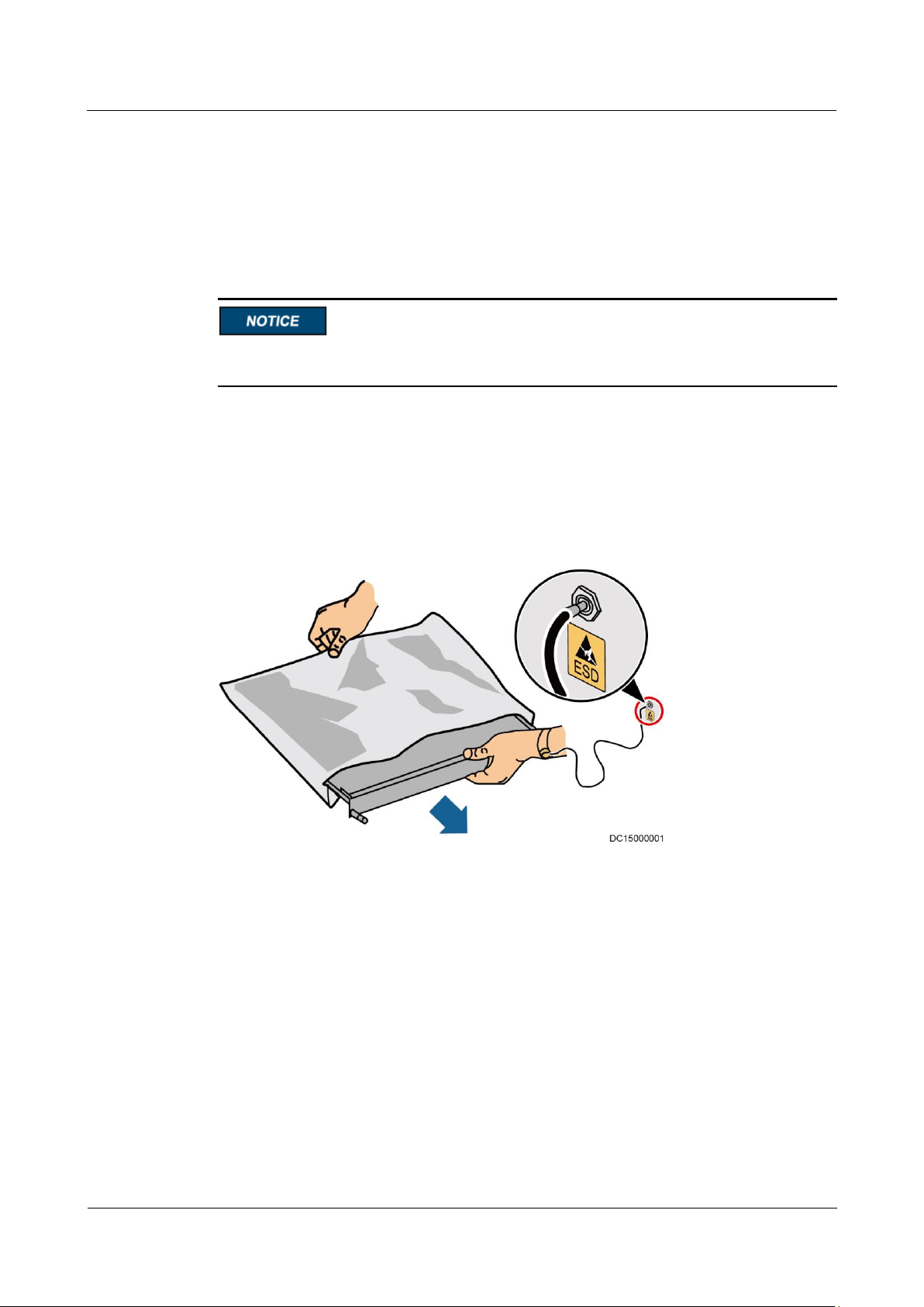
Wear a pair of ESD gloves or a well-grounded ESD wrist strap when touching the device
or handling boards or application-specific integrated circuits (ASICs).
When holding a board, hold its edge without touching any components, especially chips.
Package boards with ESD packaging materials before storing or transporting them.
Figure 1-1 shows how to wear an ESD wrist strap.
Figure 1-1 Wearing an ESD wrist strap
Liquid Prevention
Do not place the product under areas prone to water leakage, such as near air conditioner
vents, ventilation vents, or feeder windows of the equipment room. Ensure that there is
no condensation inside the product or equipment room. Ensure that no liquid enters the
product. Otherwise, short circuits will occur and may result in serious injury or death.
If any liquid is detected inside the product, immediately disconnect the power supply and
contact the administrator.
Page 15

UPS5000-A-30 kVA & 40 kVA & 80 kVA
User Manual
1 Safety Precautions
Issue 11 (2018-12-10)
Copyright © Huawei Technologies Co., Ltd.
6
1.3 Operating Environment
The UPS is used for commercial and industrial purposes only. It cannot be used as a power
supply for life support devices.
The TIER4 or TIER3 power supply architecture specified in TIA942, that is, dual power
supply routes, must be used in the power supply systems that are crucial to major economic
interests or order of public places, such as the national computing center, military command
system, emergency command center, railway signal system and control center, civil aviation
air traffic control center, airport command center, financial clearing center, and transaction
center.
The UPS operating environment must meet the requirements for the climate indicator,
mechanically active substance indicator, and chemically active substance indicator in ETSI
EN 300 019-1 class 3.6.
Do not expose the equipment or perform any operations in an environment with flammable or
explosive gas, or smoke.
Any operation on any electrical device in an environment that has flammable air can cause
extreme danger. Strictly obey the operating environmental requirements specified in related
use manuals when using or storing the device.
Do not use the UPS in the following environments:
Environment containing flammable gases, corrosive gases, abnormal vibrations, and
impacts.
Non-confined environment near the ocean (0–3.7 km) and indoor or semi-indoor
environment where the temperature and humidity are not controllable, such as a simple
equipment room near the ocean, citizen house, garage, corridor, direct ventilation cabinet,
house with only the roof, railway station platform, gymnasium, aquarium, and so on.
1.4 Battery Safety
This section describes precautions for operating batteries.
Before operating batteries, carefully read the safety precautions to ensure correct battery
handling and connection is performed, and personal safety is managed.
Page 16

UPS5000-A-30 kVA & 40 kVA & 80 kVA
User Manual
1 Safety Precautions
Issue 11 (2018-12-10)
Copyright © Huawei Technologies Co., Ltd.
7
To ensure battery safety and efficient battery management, use the batteries delivered with
the UPS. Huawei shall not be responsible for battery damage caused by using non-Huawei
batteries for Huawei UPSs.
Ensure lead-acid battery handling is in accordance with local regulations.
Incorrect handling of batteries may cause hazards. When operating batteries, avoid
battery short circuits and electrolyte overflow or leakage.
Electrolyte overflow may damage the device by corroding metal parts and circuit boards,
and ultimately damaging the circuit boards.
Short circuits caused by incorrect operations may cause serious injuries due to high
power of batteries.
Do not reversely connect positive and negative battery terminals.
Use batteries of the specified type. Otherwise, the batteries may be damaged.
Check battery connections periodically to ensure that all screws are securely tightened.
Install or store batteries in clean, cool, and dry environments.
Do not decompose, transform, or damage batteries. Otherwise, battery short circuit,
electrolyte leakage, and even personal injury may occur.
Preventative Measures
When installing and maintaining batteries, pay attention to the following points:
Use dedicated insulated tools.
Take measures to protect eyes, such as using eye protection devices.
Avoid skin contact with electrolyte overflow. Wear rubber gloves and protective
clothing.
When handling a battery, ensure that its electrodes always point upward. Do not tilt or
overturn batteries.
Switch off the power supply during installation and maintenance.
Short Circuit
Battery short circuits may cause personal injury. The high transient current generated by a
short circuit may release a surge of power and cause a fire.
To avoid battery short circuits, do not maintain batteries while they are in use.
Harmful Gas
Page 17

UPS5000-A-30 kVA & 40 kVA & 80 kVA
User Manual
1 Safety Precautions
Issue 11 (2018-12-10)
Copyright © Huawei Technologies Co., Ltd.
8
Do not use unsealed lead-acid batteries. Lead-acid batteries emit flammable gas. Therefore,
place and secure lead-acid batteries horizontally to prevent fire or corrosion.
Store lead-acid batteries in a place with good ventilation, and take fire safety precautions.
Battery Temperature
High temperature may result in battery distortion, damage, and electrolyte overflow.
Install or store batteries far away from fire sources and heating devices such as
transformers. Never burn batteries.
If the battery temperature exceeds 60°C, check the battery for electrolyte overflow. If
electrolyte overflows, handle the leakage immediately.
Electrolyte Leakage
In the case of electrolyte leakage, counteract and absorb the leaking electrolyte immediately.
When moving or handling a battery whose electrolyte leaks, note that the leaking electrolyte
may harm human bodies. If the electrolyte leaks, use the following substances to counteract
and absorb the leaking electrolyte:
Sodium bicarbonate (baking soda): NaHCO3
Sodium carbonate (soda): Na2CO3
When using substances to counteract and absorb electrolytes, strictly follow the guidelines
provided by the battery manufacturer.
If any personnel are exposed to battery electrolyte, wash the exposed area with clean water
immediately and seek medical advice if the situation is serious.
1.5 Mechanical Safety
Moving Sharp Objects
Wear protective gloves when moving sharp objects.
Page 18
UPS5000-A-30 kVA & 40 kVA & 80 kVA
User Manual
1 Safety Precautions
Issue 11 (2018-12-10)
Copyright © Huawei Technologies Co., Ltd.
9
Moving Heavy Objects
Perform operations in accordance with all instructional symbols on the device.
Take caution to avoid injury when moving heavy objects.
When moving or lifting a device, hold the handle or bottom of the device.
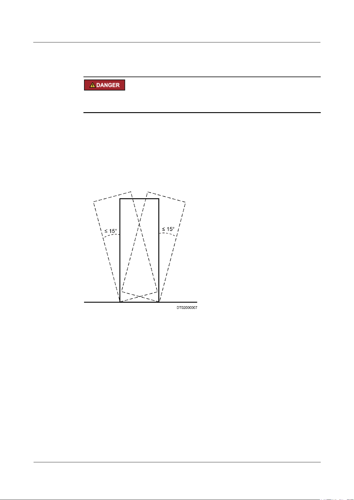
When transporting a device using a pallet truck, the forks must be properly positioned to
ensure that the device does not topple. No excessive tilt or jolt is allowed during the
transportation, and the maximum tolerance of the tilting angle during loading and
unloading is 15°. To avoid toppling, secure the device to the pallet truck by using ropes
before moving, and assign persons to watch out the device during movement.
Move the cabinet with caution. Any bumping or falling may damage the device.
Figure 1-2 Tilting angle of a cabinet
Handling Fans
Do not insert fingers or boards into the operating fans until the fans are switched off, and have
stopped running.
1.6 Laying Out Cables
Binding Signal Cables
Page 19

UPS5000-A-30 kVA & 40 kVA & 80 kVA
User Manual
1 Safety Precautions
Issue 11 (2018-12-10)
Copyright © Huawei Technologies Co., Ltd.
10
Signal cables must be bound separately from strong-current cables and high-voltage cables.
Laying Out Cables
When the temperature is low, a violent strike or vibrations may damage the cable sheathing.
To ensure cable safety, comply with the following requirements:
Cables can be laid, or installed, only when the temperature is higher than 0°C (32°F).
Handle cables with caution, especially at lower temperatures.
Before laying out cables that have been stored in temperatures lower than 0°C (32°F),
move the cables to an environment that is at the requisite ambient temperature. Store
them in this environment for at least 24 hours.
Do not drop the cables directly from the vehicle.
As the insulation layer of a cable may age, or be damaged from high temperatures,
ensure a sufficient distance between cables and the DC busbars, shunts, and fuses.
Cables prepared by the customer should be flame resistant. Cables must not be routed
behind the air exhaust vent of the cabinet. The air exhaust vent should not be blocked by
any object.
Before connecting a cable, ensure that the cable and cable label to be used meet the actual
installation requirements.
1.7 Information About Foreign Objects near UPS Equipment Installation
The purpose of this note is to provide information and warnings about the potential risks of
the operational integrity of an installed UPS. These risks are caused by foreign objects in or
near the UPS modules and relevant auxiliary equipment/components.
These risks are particularly high if conductive materials have entered the UPS modules/units
or the channels in the relevant auxiliary equipment/components.
Potential risks include damage to installed UPS equipment and subsequent power derating
and power failure of loads at critical positions.
Huawei UPS uses the highest safety standard in equipment design to ensure that live parts are
not in contact with the exterior and that no foreign object will enter the equipment during
operation.
However, when the UPS baffle plate and cover are open and the electrical wiring terminals
are exposed by the electrical contractor/installation personnel who are setting up a power line
connection, it is almost impossible to ensure that no foreign object will enter Huawei UPS
during onsite installation.
It is common to have someone working in the same room as the UPS during onsite
installation. Sometimes some people may be working above the UPS and relevant auxiliary
equipment/components.
To avoid serious damage to the onsite operation, property hazards, and personal injury
including fatal injury, it is the responsibility of each equipment manager or construction
Page 20

UPS5000-A-30 kVA & 40 kVA & 80 kVA
User Manual
1 Safety Precautions
Issue 11 (2018-12-10)
Copyright © Huawei Technologies Co., Ltd.
11
manager to ensure that no foreign object enters the UPS modules/units or relevant auxiliary
equipment/components.
Page 21
UPS5000-A-30 kVA & 40 kVA & 80 kVA
User Manual
2 Overview
Issue 11 (2018-12-10)
Copyright © Huawei Technologies Co., Ltd.
12
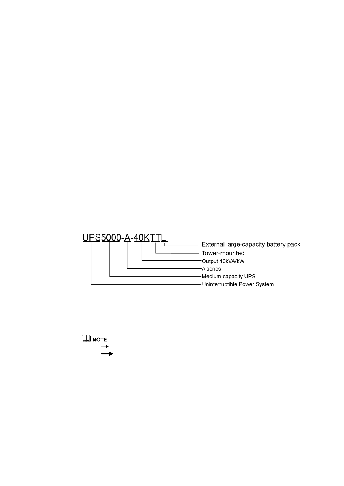
2.1 Model Description
This document describes the following UPS models:
UPS5000-A-30KTTL
UPS5000-A-40KTTL
UPS5000-A-80KTTL
2 Overview
Figure 2-1 Model number
2.2 Working Principles
indicates an input mode.
2.2.1 Conceptual Diagram
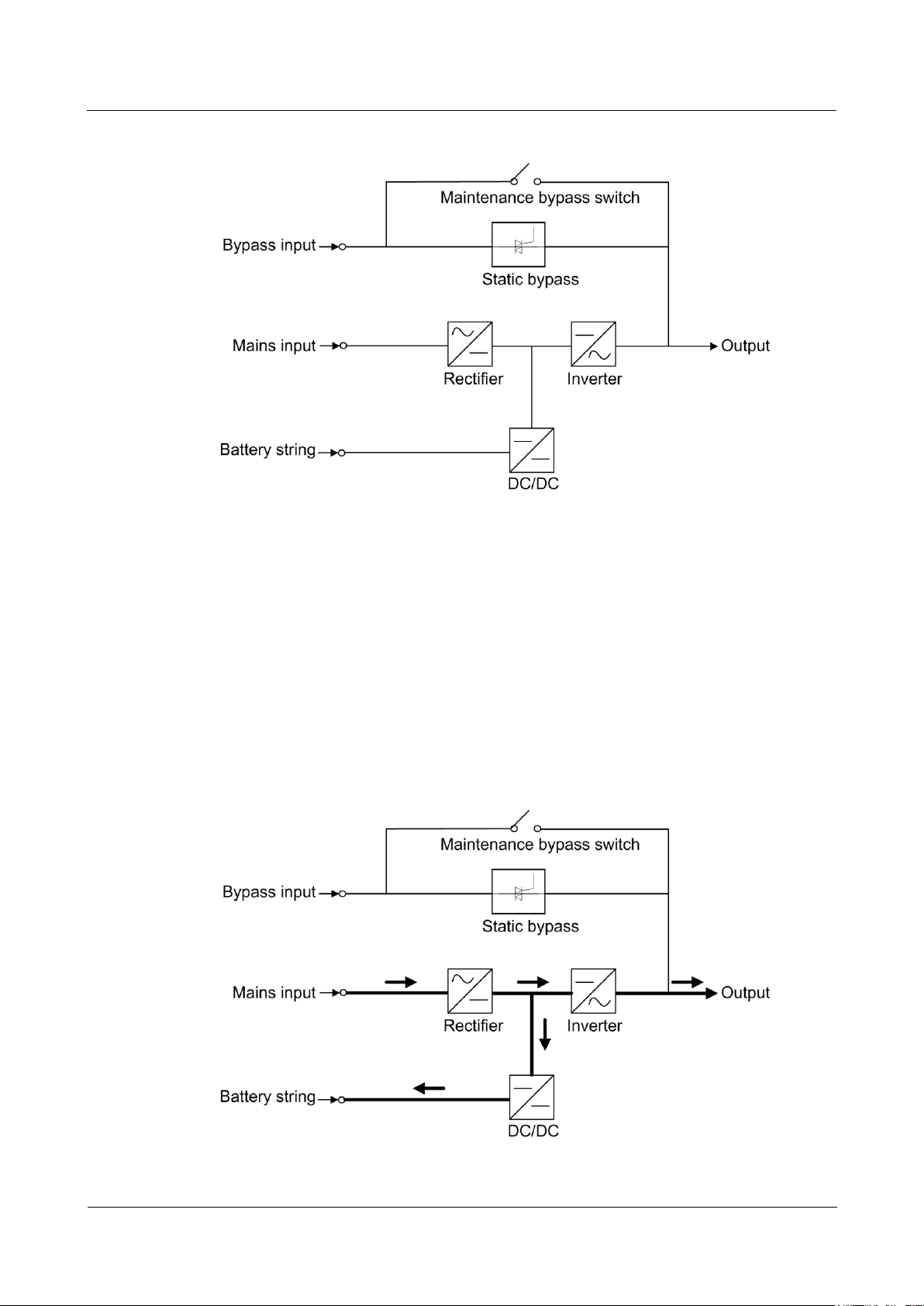
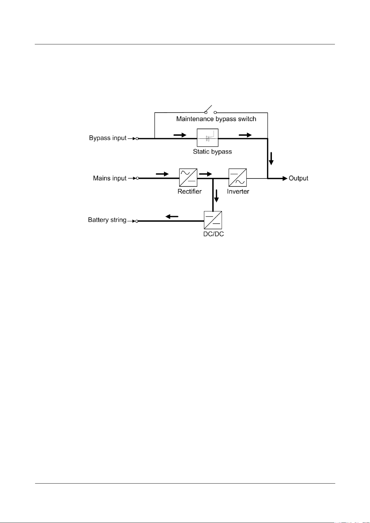
The UPS5000-A is an online double-conversion UPS that uses digital signal processing (DSP)
technology and features high efficiency and high power density. Figure 2-2 shows a
conceptual diagram for the UPS.
indicates the energy flow direction.
Page 22
UPS5000-A-30 kVA & 40 kVA & 80 kVA
User Manual
2 Overview
Issue 11 (2018-12-10)
Copyright © Huawei Technologies Co., Ltd.
13
Figure 2-2 UPS conceptual diagram
2.2.2 Working Modes
2.2.2.1 Normal Mode
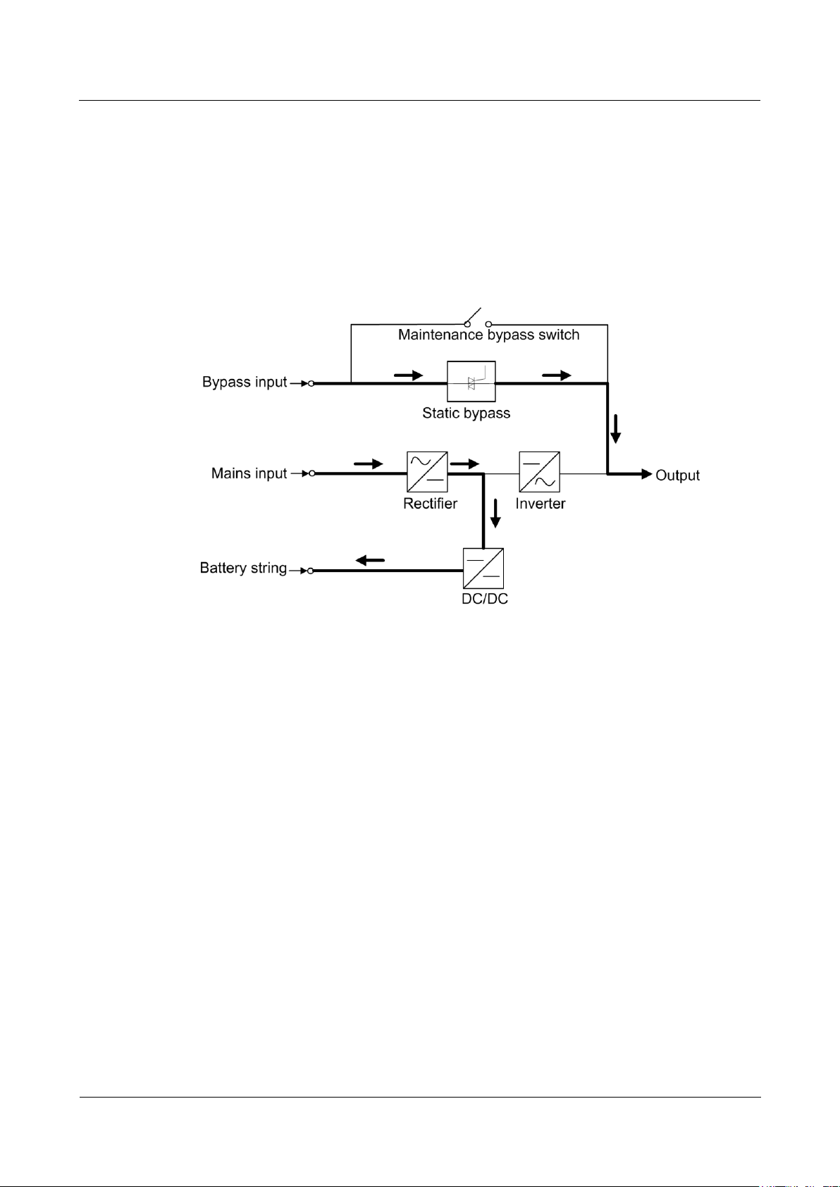
When the UPS works in normal mode, the rectifier converts the AC input voltage into the DC
voltage, which is then raised to the bus voltage by the power factor correction (PFC) circuit.
Then one part of the voltage passes through the DC-DC circuit to charge the battery string,
and the other part is converted by the inverter into AC voltage outputs. The two conversions
ensure high-precision and high-quality output voltages, protecting loads from interferences
such as input harmonics, burrs, and voltage transients. Figure 2-3 shows the conceptual
diagram of the UPS working in normal mode.
Figure 2-3 UPS conceptual diagram in normal mode
Page 23
UPS5000-A-30 kVA & 40 kVA & 80 kVA
User Manual
2 Overview
Issue 11 (2018-12-10)
Copyright © Huawei Technologies Co., Ltd.
14
2.2.2.2 Bypass Mode
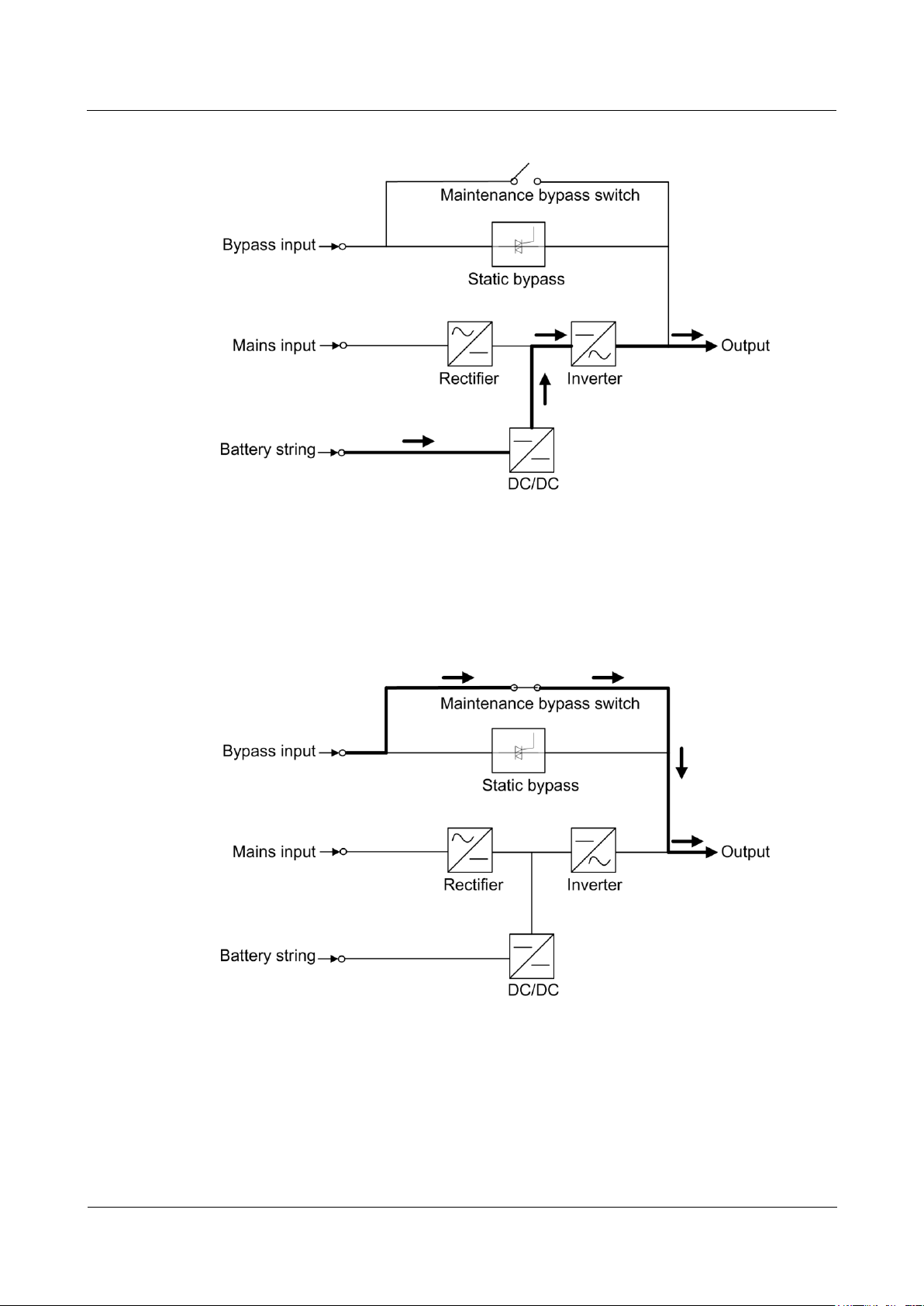
If the inverter does not start or is manually shut down after the UPS is powered on, the bypass
supplies power to loads. The UPS automatically transfers from normal mode to bypass mode
if it detects power unit overtemperature, overload, or other faults that may cause the inverter
to shut down. The bypass power supply is not protected by the UPS which means it may be
affected by mains outage, and incorrect AC voltage or frequency. Figure 2-4 shows a
conceptual diagram of the UPS working in bypass mode.
Figure 2-4 UPS conceptual diagram in bypass mode
2.2.2.3 Battery Mode
If the AC input voltage is not normal, the UPS transfers to battery mode to obtain power from
batteries. The inverter then converts the power into AC outputs. Figure 2-5 shows a
conceptual diagram of the UPS working in battery mode.
Page 24
UPS5000-A-30 kVA & 40 kVA & 80 kVA
User Manual
2 Overview
Issue 11 (2018-12-10)
Copyright © Huawei Technologies Co., Ltd.
15
Figure 2-5 UPS conceptual diagram in battery mode
2.2.2.4 Maintenance Bypass Mode
The current flows through the maintenance bypass, instead of the power unit or bypass unit.
UPS maintenance can be performed in this mode.
Figure 2-6 UPS conceptual diagram in maintenance bypass mode
2.2.2.5 ECO Mode
The economy control operation (ECO) mode is an energy-saving mode, which you can
configure on the liquid crystal display (LCD) or web user interface (WebUI). In ECO mode,
when the bypass input voltage is within the ECO voltage range, the bypass combined switch
turns on, and the bypass supplies power. When the bypass input voltage is beyond the ECO
Page 25
UPS5000-A-30 kVA & 40 kVA & 80 kVA
User Manual
2 Overview
Issue 11 (2018-12-10)
Copyright © Huawei Technologies Co., Ltd.
16
voltage range, the UPS transfers from bypass mode to normal mode. In bypass mode or
normal mode, the rectifier keeps working and charges batteries using a charger. The ECO
mode delivers a higher efficiency. Figure 2-7 shows a conceptual diagram of the UPS working
in ECO mode.
Figure 2-7 UPS conceptual diagram in ECO mode
Page 26
UPS5000-A-30 kVA & 40 kVA & 80 kVA
User Manual
2 Overview
Issue 11 (2018-12-10)
Copyright © Huawei Technologies Co., Ltd.
17
2.3 Product Description
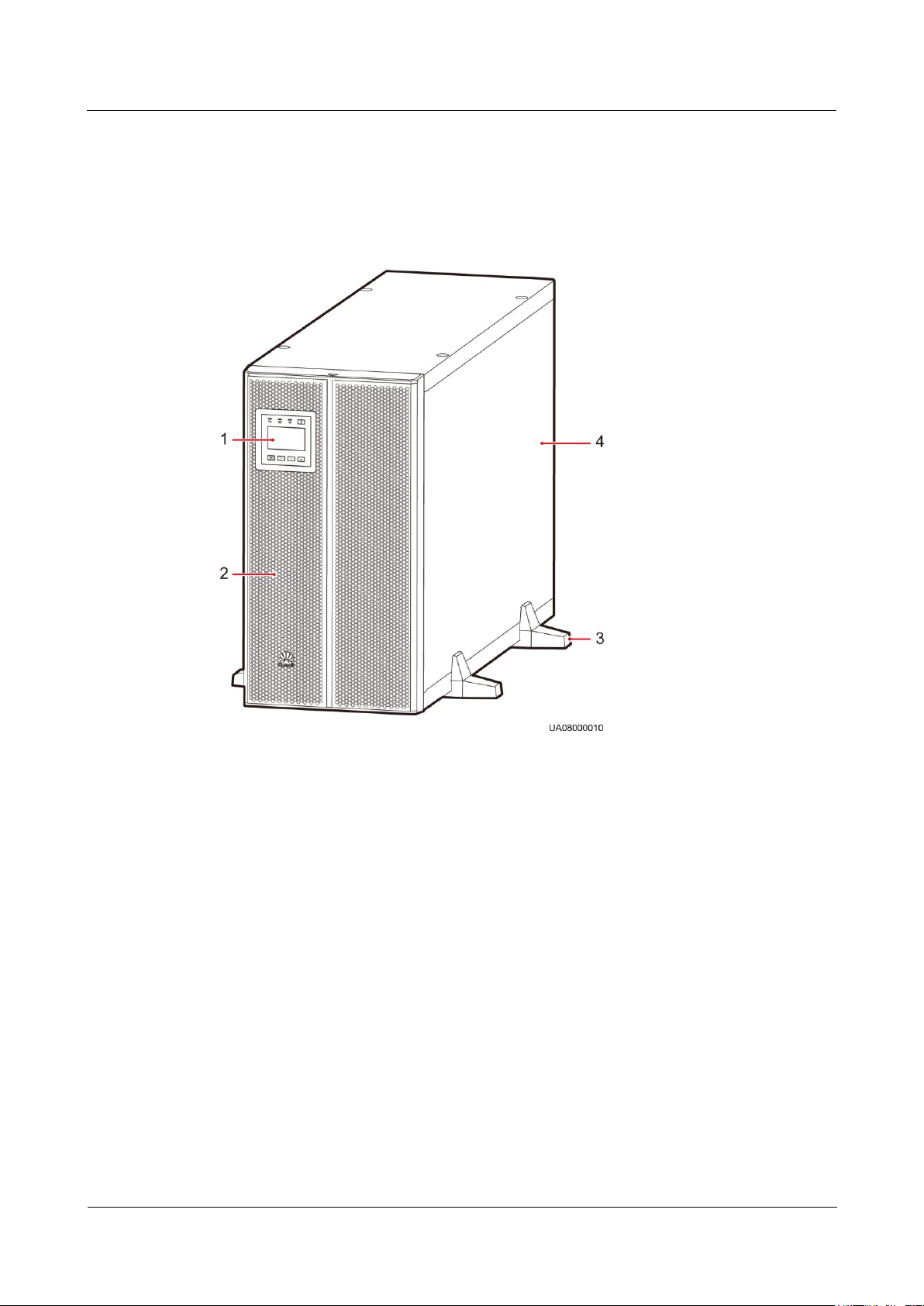
(1) Monitor display unit (MDU)
(2) Front panel
(3) Support base
(4) Chassis
2.3.1 Appearance
Figure 2-8 UPS5000-A-30 kVA/40 kVA
Page 27
UPS5000-A-30 kVA & 40 kVA & 80 kVA
User Manual
2 Overview
Issue 11 (2018-12-10)
Copyright © Huawei Technologies Co., Ltd.
18
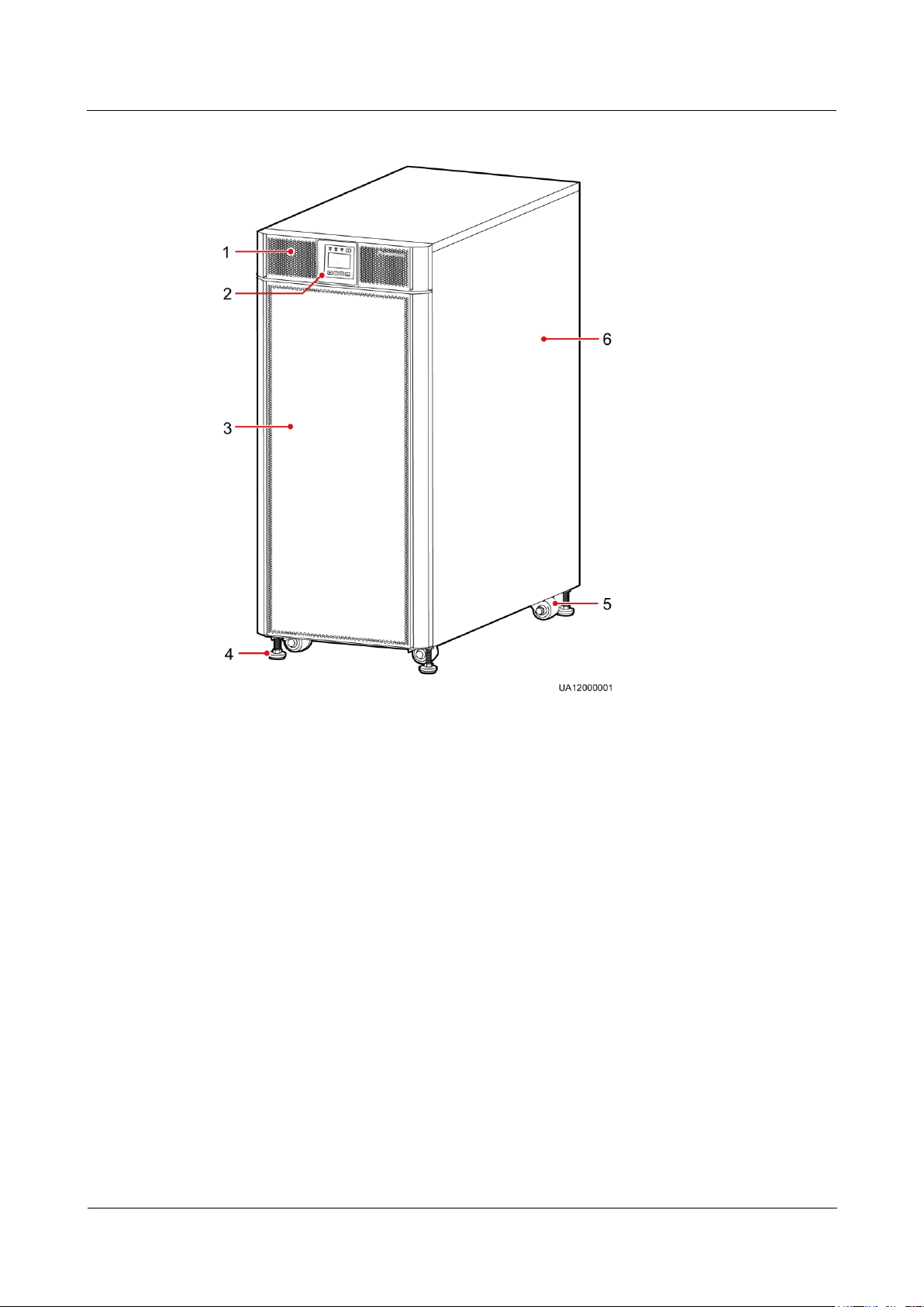
Figure 2-9 UPS5000-A-80 kVA
(1) Front panel 1
(2) MDU
(3) Front panel 2
(4) Leveling foot
(5) Castor
(6) Chassis
2.3.2 Product Structure
2.3.2.1 30 kVA/40 kVA UPS
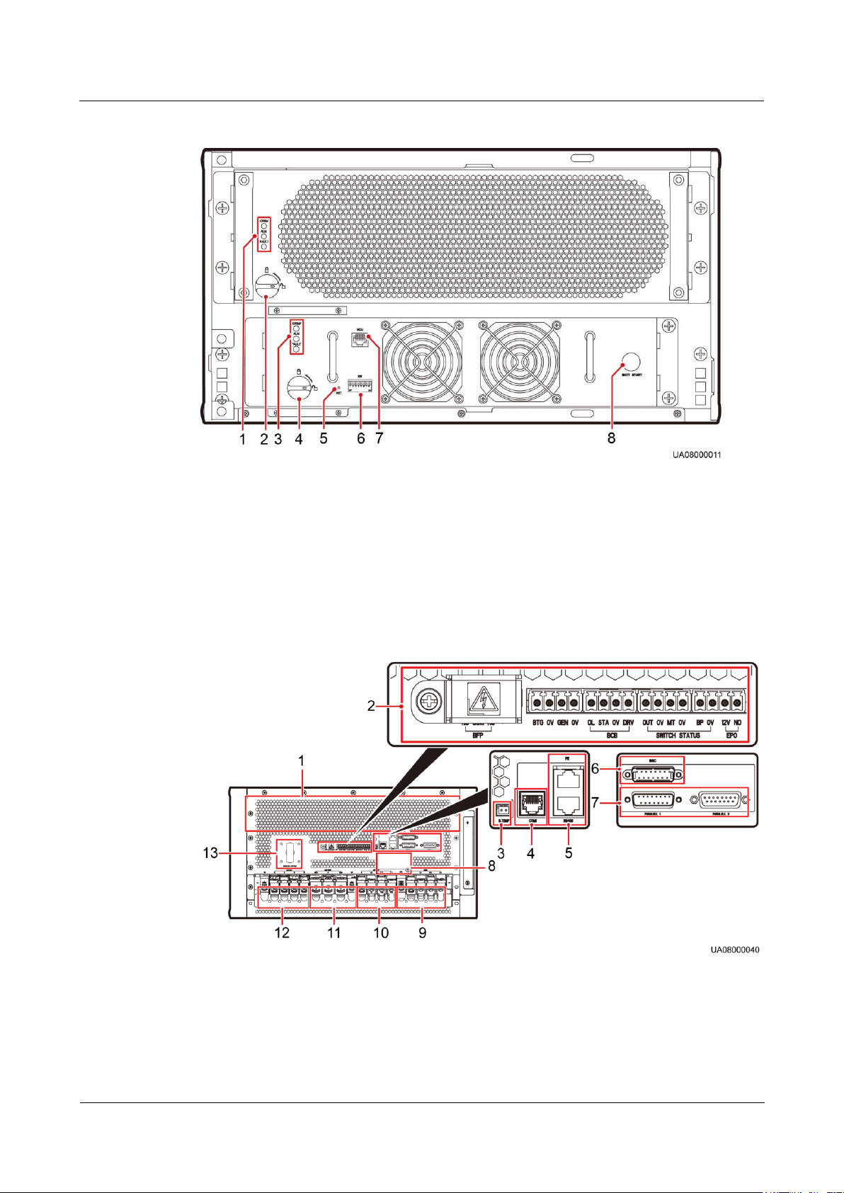
Figure 2-10 and Figure 2-11 show the architecture of the UPS5000-A-30 kVA/40 kVA. Figure
2-10 shows the UPS with the front panel and the MDU removed.
Page 28
UPS5000-A-30 kVA & 40 kVA & 80 kVA
User Manual
2 Overview
Issue 11 (2018-12-10)
Copyright © Huawei Technologies Co., Ltd.
19
Figure 2-10 UPS5000-A-30 kVA/40 kVA product structure (front view)
(1) Power unit
indicators
(2) Power unit ready
switch
(3) Bypass unit
indicators
(4) Bypass unit
ready switch
(5) MDU reset
button
(6) Dual in-line package
(DIP) switch
(7) MDU port
(8) Cold-start button
(1) Ventilation
panel on the rear
panel
(2) Dry contacts
(3) Battery
temperature sensor
port
(4) Ambient temperature
and humidity sensor port
or battery monitoring unit
(BMU) port
Figure 2-11 UPS5000-A-30 kVA/40 kVA product structure (rear view and enlarged view of
certain parts)
Page 29
UPS5000-A-30 kVA & 40 kVA & 80 kVA
User Manual
2 Overview
Issue 11 (2018-12-10)
Copyright © Huawei Technologies Co., Ltd.
20
(5) FE port (upper)
and RS485 port
(lower)
(6) BSC port
(7) Parallel ports
(8) Slot for dry contact
card (optional)
(9) UPS mains
input terminals
(under the cover)
(10) UPS bypass
input terminals
(under the cover)
(11) Battery
wiring terminals
(under the cover)
(12) UPS output terminals
(under the cover)
(13) Maintenance
bypass switch
Indicators
DIP
Swit
ch
DIP1
DIP2
DIP3
LCD
Operation
Function
Remarks
Statu
s 1
OFF
OFF
OFF
N/A
Not
defined.
N/A
Connect the BMU by using a 04080298 transfer cable, which is delivered with the BMU.
When no ambient temperature and humidity sensor is installed, connect the BMU to the COM1 port
on the UPS.
When an ambient temperature and humidity sensor is installed, connect the BMU to the
RS485_OUT port on the sensor.
Both the power unit and bypass unit provide the Run indicator, Alarm indicator, and Fault
indicator (from top down).
MDU Reset Button
If the MDU does not work properly, use this button to reset the MDU, without affecting
power supply.
DIP Switch
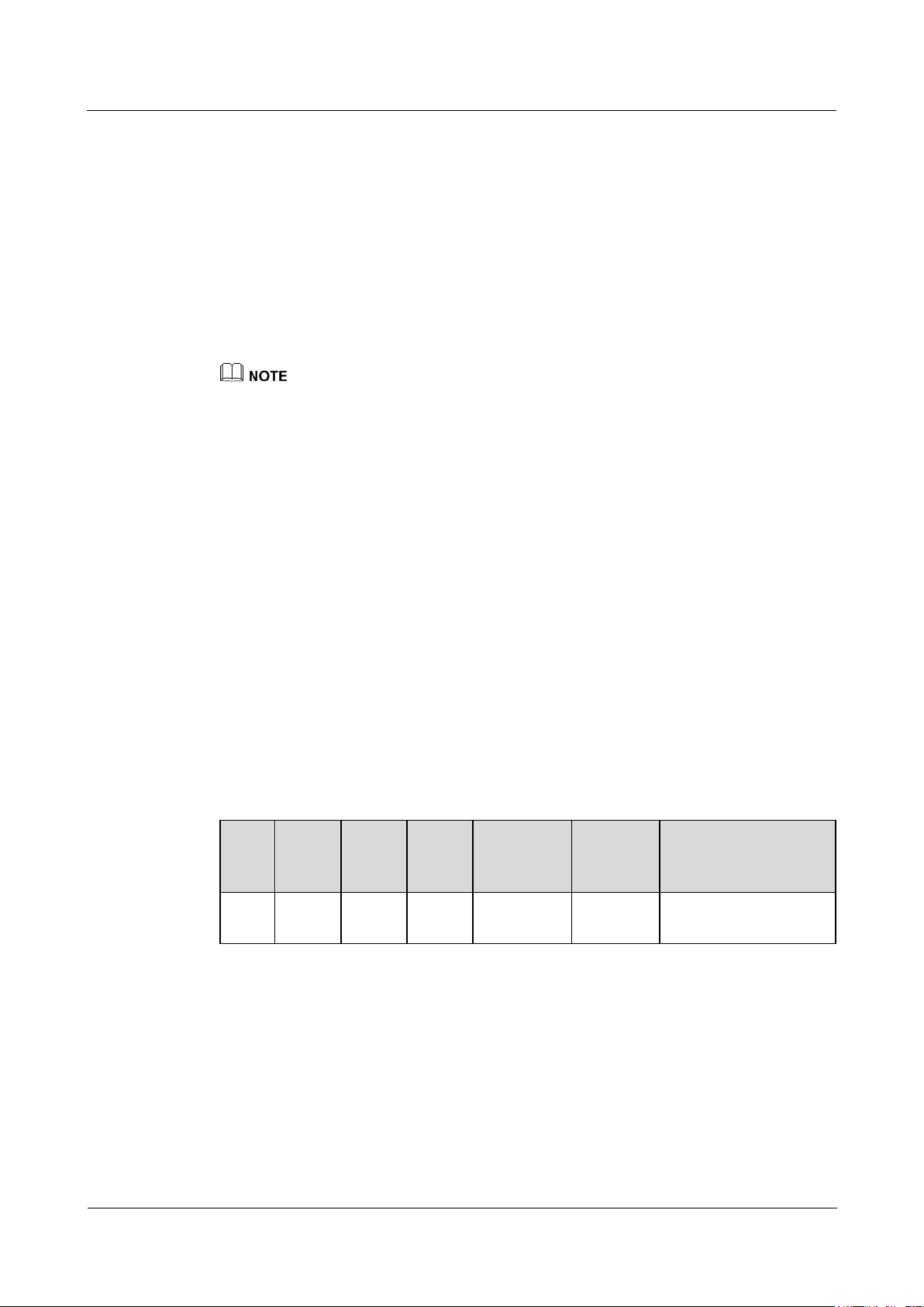
Typically, three toggle switches are reserved for function settings. Table 2-1 describes the DIP
switch status.
Table 2-1 DIP switch status
Page 30

UPS5000-A-30 kVA & 40 kVA & 80 kVA
User Manual
2 Overview
Issue 11 (2018-12-10)
Copyright © Huawei Technologies Co., Ltd.
21
DIP
Swit
ch
DIP1
DIP2
DIP3
LCD
Operation
Function
Remarks
Statu
s 2
ON
ON
OFF
Settings >
Restore
Default
Settings
Restores
factory
defaults.
After clearing system
parameters, battery
parameters, monitoring
parameters, and logs
(operation logs, upgrade
logs, and battery test
and statistics logs), the
MDU does not restart
automatically. The
settings will take effect
after the MDU is
powered on again.
Statu
s 3
ON
OFF
ON
Hold down
the Up and
Down
buttons at
the same
time for 5s.
Restores
the user
name and
password.
After restoring the
preset user name and
password, the MDU
restarts automatically,
without affecting power
supply.
Statu
s 4
ON
OFF
OFF
Control >
Clear
historical
alarms
Clears
historical
alarm
records.
After clearing historical
alarm records, the MDU
restarts automatically.
Statu
s 5
OFF
ON
ON
Control >
Clear
operation
logs
Clears
operation
logs.
After clearing operation
logs, the MDU restarts
automatically.
Statu
s 6
OFF
ON
OFF
Settings >
Advanced
Param. >
Work
mode >
Self-load
mode
Sets
self-load
mode.
After entering self-load
mode subsequent to
inverter startup, the
MDU does not restart
automatically.
Statu
s 7
OFF
OFF
ON
-
Not
defined.
-
Statu
s 8
ON
ON
ON
-
Not
defined.
-
Page 31
UPS5000-A-30 kVA & 40 kVA & 80 kVA
User Manual
2 Overview
Issue 11 (2018-12-10)
Copyright © Huawei Technologies Co., Ltd.
22
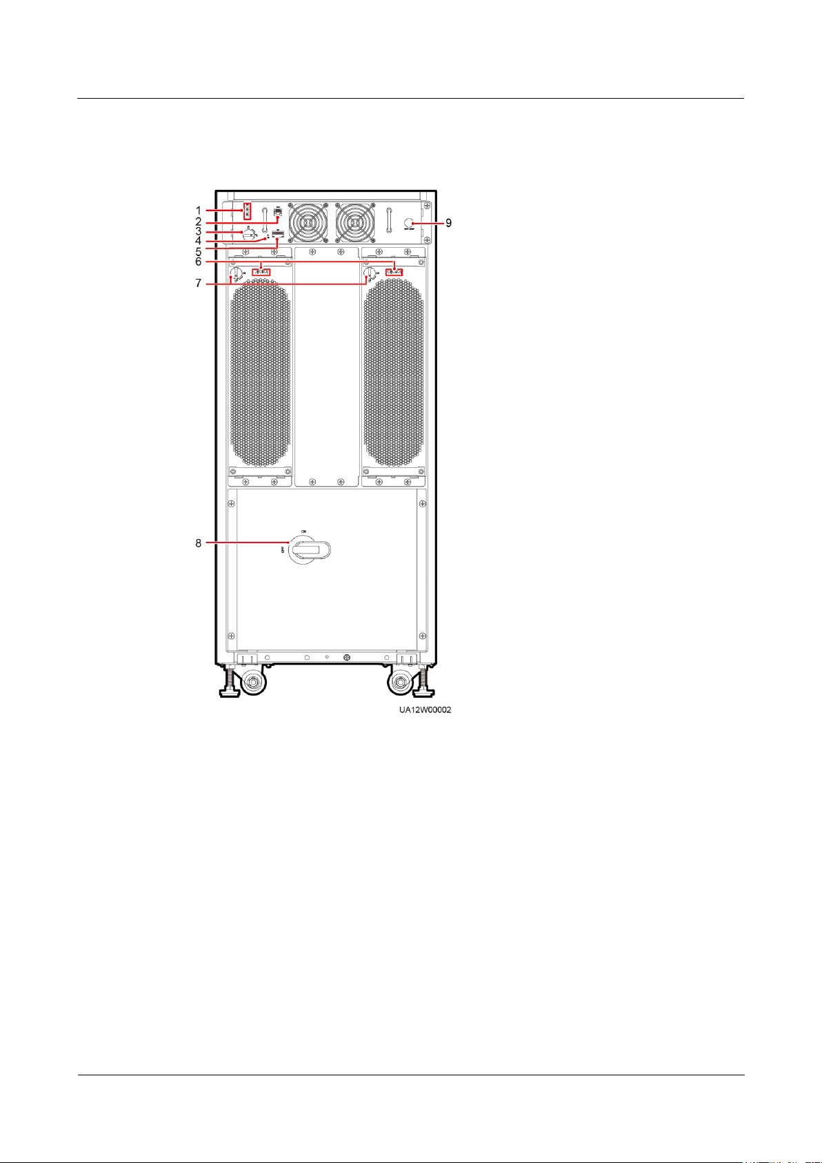
2.3.2.2 80kVA UPS
(1) Bypass unit indicators
(2) MDU port
(3) Bypass unit ready
switch
(4) MDU reset button
(5) DIP switch
(6) Power unit indicators
(7) Power unit ready
switch
(8) Maintenance bypass
switch
(9) Cold-start button
Figure 2-12 UPS5000-A-80 kVA product structure (front view)
Page 32
UPS5000-A-30 kVA & 40 kVA & 80 kVA
User Manual
2 Overview
Issue 11 (2018-12-10)
Copyright © Huawei Technologies Co., Ltd.
23
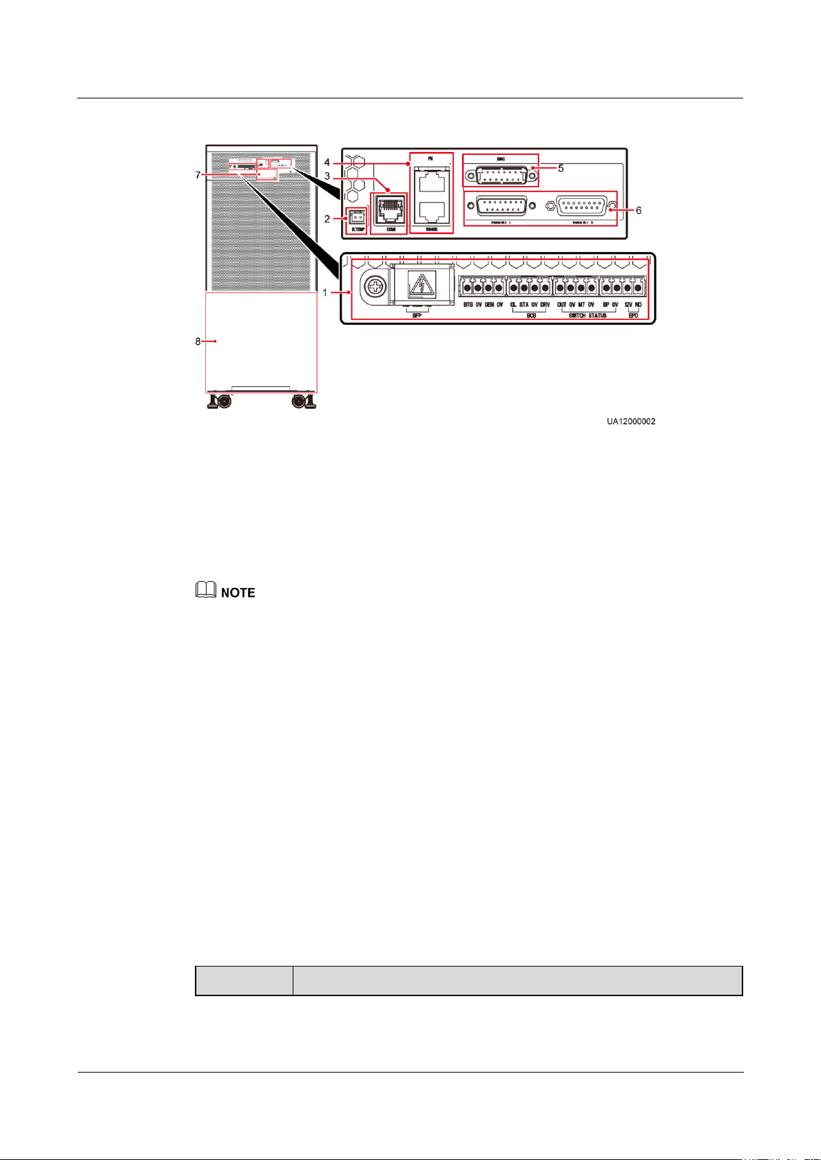
Figure 2-13 UPS5000-A-80 kVA product structure (rear view and enlarged view of certain part)
(1) Dry
contacts
(2) Battery
temperature sensor
port
(3) Ambient temperature and
humidity sensor port or BMU
port
(4) FE port (upper)
and RS485 port
(lower)
(5) BSC
port
(6) Parallel ports
(7) Slot for dry contact card
(optional)
(8) PDU
Silk Screen
Description
UPS5000-A-80 kVA functional components have the same functions as UPS5000-A-30 kVA/40 kVA
functional components. For details, see section 2.3.2.1 30 kVA/40 kVA UPS.
Connect the BMU by using a 04080298 transfer cable, which is delivered with the BMU.
When no ambient temperature and humidity sensor is installed, connect the BMU to the COM1 port
on the UPS.
When an ambient temperature and humidity sensor is installed, connect the BMU to the
RS485_OUT port on the sensor.
2.3.3 Control Port
The UPS5000-A provides a communications slot, a fast Ethernet (FE) port, an RS485 port,
parallel ports, a BSC port, basic dry contacts, and other control signal ports.
Parallel Port and BSC Port
To connect UPSs in parallel, use a parallel cable to connect the parallel ports on the ECMs on
the two UPSs. A hot swappable BSC is used in a dual-bus system to process the
communication information of two UPS systems. Table 2-2 describes the functions of the
parallel port and BSC port.
Table 2-2 Functions of the parallel port and BSC port
Page 33

UPS5000-A-30 kVA & 40 kVA & 80 kVA
User Manual
2 Overview
Issue 11 (2018-12-10)
Copyright © Huawei Technologies Co., Ltd.
24
Silk Screen
Description
PARALLEL
The PARALLEL port transmits parallel signals. To connect multiple UPSs
in parallel, use parallel cables to connect the parallel ports on the UPSs. N
UPSs require N parallel cables so that two parallel cables are connected to
each UPS, which improves parallel connection reliability.
BSC
This port is used in a dual-bus system to balance output frequencies and
phases between UPS systems, ensuring that two buses can switch with
each other. The BSC port processes UPS system communications
information.
Dry Contacts
Silk Screen
Description
Status
BFP_NO
Triggers bypass backfeed
protection.
Normally, the COM and NC
dry contacts are closed. If
bypass backfeed occurs, the
COM and NO dry contacts are
closed, opening the bypass
input circuit breaker.
BFP_COM
BFP_NC
/
Reserved
N/A
BTG
Detects battery grounding
failures.
Status:
Closed: battery grounding
failure
Open: no battery
grounding failure
The initial status is Open.
0V
Port for signal ground
GEN
Detects diesel generator
(D.G.) mode.
Status:
Closed: D.G. mode
Open: non-D.G. mode
The initial status is Open.
0V
Port for signal ground
BCB_OL
Detects the battery circuit
breaker (BCB) box.
Status:
Grounded: BCB box
connected
Floated: BCB box not
connected
The initial status is Grounded.
The dry contacts allow the UPS to manage the battery system including the external battery
switch and battery monitoring unit (BMU). They also allow the UPS to provide alarm signals
for external devices and implement remote emergency power-off (EPO). Table 2-3 describes
the dry contacts.
Table 2-3 Dry contacts
Page 34

UPS5000-A-30 kVA & 40 kVA & 80 kVA
User Manual
2 Overview
Issue 11 (2018-12-10)
Copyright © Huawei Technologies Co., Ltd.
25
Silk Screen
Description
Status
BCB_STA
Monitors the battery circuit
breaker.
Status:
Closed: battery circuit
breaker ON
Open: battery circuit
breaker OFF
The initial status is Open.
BCB_0V
Port for signal ground
N/A
BCB_DRV
Controls the trip of the
battery switch in the BCB
box.
Voltage:
0 V: battery switch not
tripped
12 V: battery switch
tripped
The initial port voltage is 0 V.
SWITCH STATUS_OUT
Monitors the UPS output
circuit breaker on the output
power distribution cabinet
(PDC).
Status:
Open: circuit breaker OFF
Closed: circuit breaker ON
The initial status is Closed.
SWITCH STATUS_0V
Port for signal ground
N/A
SWITCH STATUS_MT
Monitors the maintenance
circuit breaker on the output
PDC.
Status:
Open: circuit breaker ON
Closed: circuit breaker
OFF
The initial status is Open.
SWITCH STATUS_0V
Port for signal ground
N/A
SWITCH STATUS_BP
Monitors the bypass input
circuit breaker on the input
PDC.
Status:
Open: circuit breaker OFF
Closed: circuit breaker ON
The initial status is Closed.
SWITCH STATUS_0V
Port for signal ground
N/A
EPO_12V
12 V power supply
N/A
EPO_NO
Triggers EPO.
The initial status is Open.
EPO is triggered if the dry
contact is closed.
NO is short for normally open, and NC is short for normally closed.
When the dry contact signal cable of an external device connects to UPS dry contacts, ensure that
the silk screen names of the dry contacts at both ends of the cable match with each other.
Page 35
UPS5000-A-30 kVA & 40 kVA & 80 kVA
User Manual
2 Overview
Issue 11 (2018-12-10)
Copyright © Huawei Technologies Co., Ltd.
26
Others
Port
Silk Screen
Description
Battery
temperature
sensor port
B_TEMP
Connects to the indoor battery temperature sensor.
Southbound
communication
port 1
COM1
Connects to an ambient temperature and humidity
sensor or BMU over two wires.
Northbound
communications
port
FE
Connects to the network port on a PC.
RS485
Connects to a northbound network management
device or third-party network management device
over two wires.
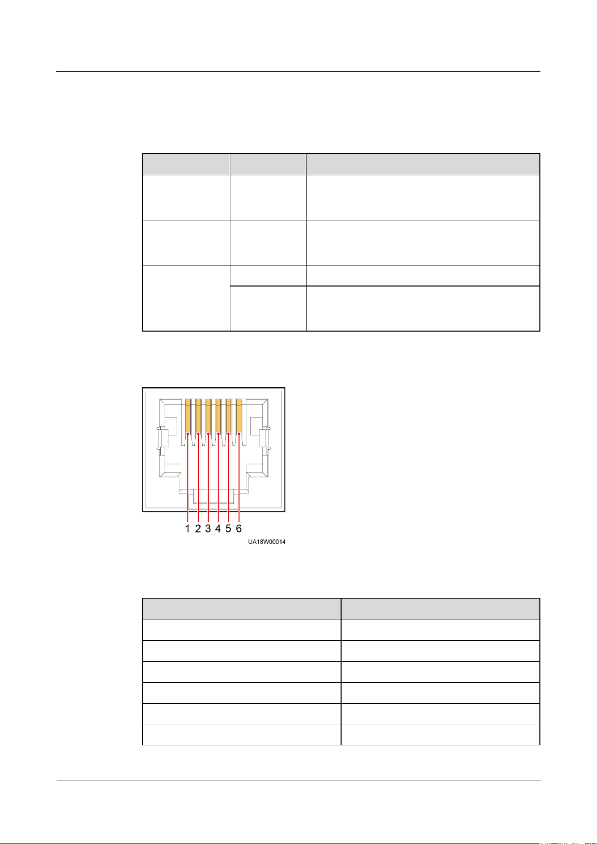
Pin
Description
1
GND
2
N/A
3
RS485-
4
RS485+
5
N/A
6
12V_PORT
Table 2-4 describes other control signal ports.
Table 2-4 Signal ports
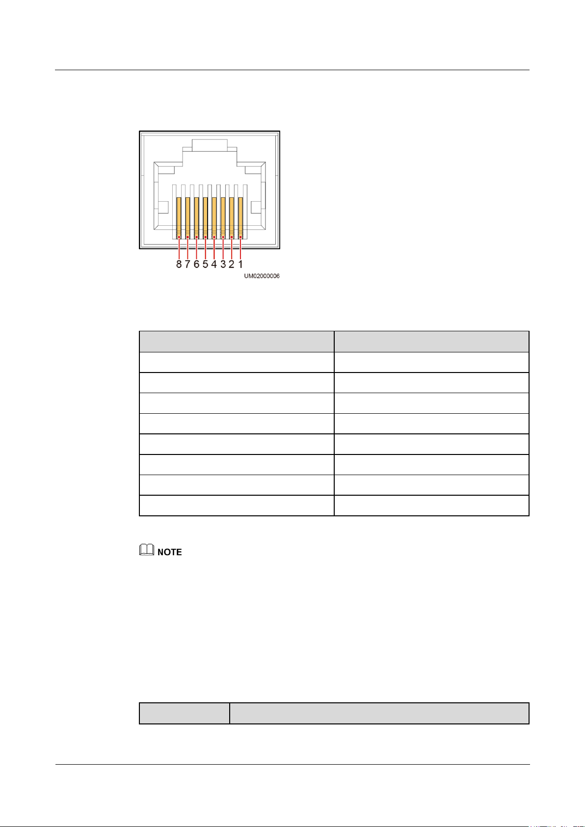
Figure 2-14 COM1 pins
Table 2-5 COM1 pin definition
Page 36
UPS5000-A-30 kVA & 40 kVA & 80 kVA
User Manual
2 Overview
Issue 11 (2018-12-10)
Copyright © Huawei Technologies Co., Ltd.
27
Pin
Description
1
RS485_T+
2
RS485_T-
3
N/A
4
RS485_R+
5
RS485_R-
6
GND
7
N/A
8
N/A
Configuration
Application Scenario
Figure 2-15 RS485 pins
Table 2-6 RS485 pin definition
If cables are prepared onsite, follow the three methods below:
Connect pin 1 and pin 2. Pin 1 connects to RS485+ and pin 2 connects to RS485–.
Connect pin 4 and pin 5. Pin 4 connects to RS485+ and pin 5 connects to RS485–.
Connect pins 1, 2, 4, and 5. Twist cables to pin 1 and pin 4 into one cable and then connect it to
RS485+. Twist cables to pin 2 and pin 5 into one cable and then connect it to RS485–.
2.4 Typical configurations
Table 2-7 Typical UPS configurations
Page 37

UPS5000-A-30 kVA & 40 kVA & 80 kVA
User Manual
2 Overview
Issue 11 (2018-12-10)
Copyright © Huawei Technologies Co., Ltd.
28
Configuration
Application Scenario
Single UPS
Supplies power to common loads.
Parallel system
Supplies power to important loads in small- and medium-sized data
centers. It features high availability and strong transient overload
capability.
Dual-bus system
The dual-bus system is suitable for scenarios where high availability
requirements are posed for power supply. The dual-bus system
supplies power to important loads in large- and medium-sized
equipment rooms and data centers.
In addition to common parallel system advantages, the dual-bus
system also provides outstanding availability and eliminates
bottleneck failures. However, configuration of the dual-bus system is
complex.
A 1+1 parallel system is a typical configuration. You can set the number of requisite UPSs and
redundant ones on the LCD or WebUI.
2.4.1 Single UPS
The UPS5000-A is a high frequency tower-mounted UPS. It uses a unit-level design to handle
power functionality, and provides an embedded maintenance bypass switch to ensure
maintenance with power on. Figure 2-2 shows the conceptual diagram of a single UPS.
2.4.2 Parallel System
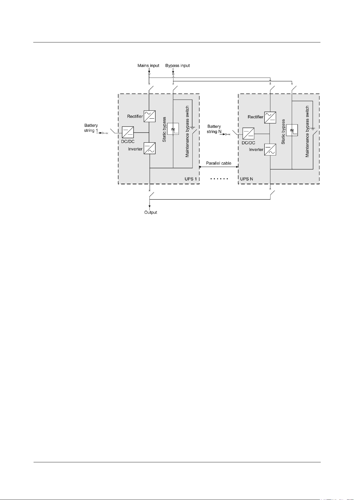
In a parallel system, the mains input, bypass input, and AC output terminals between cabinets
are connected in parallel. Energy control modules (ECMs) on each UPS are connected over
parallel cables. The parallel connections synchronize the UPS outputs to supply power to
loads. If one UPS fails, the other UPSs continue supplying power to loads.
Page 38
UPS5000-A-30 kVA & 40 kVA & 80 kVA
User Manual
2 Overview
Issue 11 (2018-12-10)
Copyright © Huawei Technologies Co., Ltd.
29
Figure 2-16 Conceptual diagram of an N+X parallel system
2.4.3 Dual-Bus System
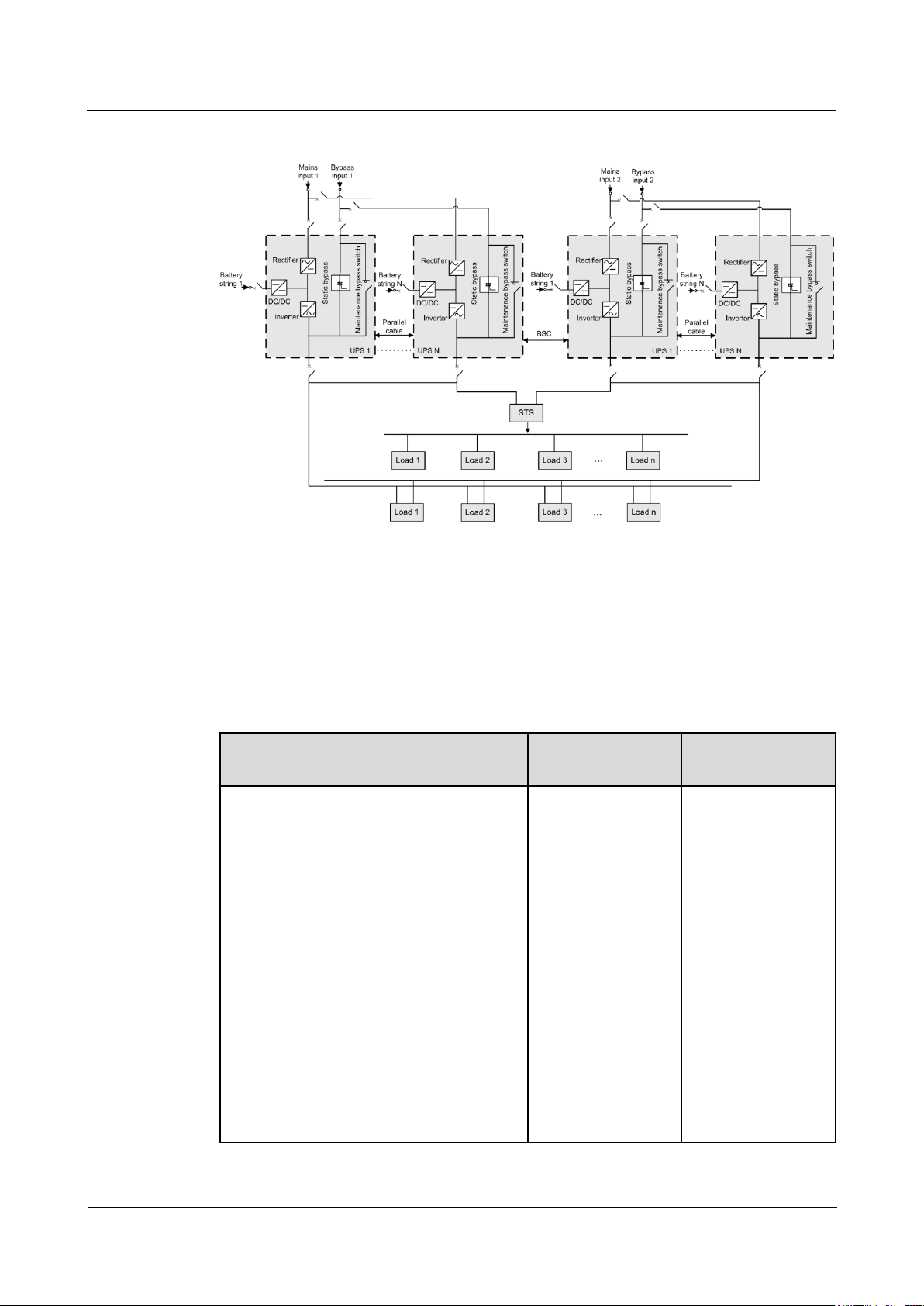
A dual-bus system consists of two independent UPS systems. Each of these UPS systems in
turn consists of one or more UPSs connected in parallel. Of the two UPS systems, one is a
master system, and the other is a slave system. This design makes the dual-bus system highly
reliable and suitable for loads with multiple input terminals. An optional static transfer switch
(STS) can be installed to start the bus synchronization controller (BSC). The UPS systems
work in normal mode or bypass mode.
Page 39
UPS5000-A-30 kVA & 40 kVA & 80 kVA
User Manual
2 Overview
Issue 11 (2018-12-10)
Copyright © Huawei Technologies Co., Ltd.
30
Figure 2-17 Conceptual diagram of a dual-bus system
Component
Model
Function
Reference
Document
BCB-BOX
PDC-0250DC03
84BXA
PDC-0400DC03
84BXA
PDC-0630DC03
84BXA
PDU8000-0125D
CV8-BXA001
PDU8000-0250D
CV8-BXA001
PDU8000-0400D
CV8-BXA001
PDU8000-0630D
CV8-BXA001
PDU8000-0800D
CV8-BXA001
Controls the
connection
between battery
strings and the
UPS.
Provides
overload
protection,
short-circuit
protection, and
remote trip
control.
PDU8000-(0125,
0250, 0400, 0630,
0800)
DCV8-BXA001 BCB
Box User Manual
2.5 Optional Components
The UPS5000-A provides a variety of optional components to address various customer
requirements.
Table 2-8 Optional components
Page 40

UPS5000-A-30 kVA & 40 kVA & 80 kVA
User Manual
2 Overview
Issue 11 (2018-12-10)
Copyright © Huawei Technologies Co., Ltd.
31
Component
Model
Function
Reference
Document
Battery bus bar
(BBB) box
PDU8000-0630D
CV8-BGA001
PDU8000-1250D
CV8-BGA001
PDU8000-2000D
CV8-BGA001
Converges the
energy of multiple
battery strings.
PDU8000-(0630,
1250, 2000)
DCV8-BGA001 BBB
Box User Manual
Antiseismic kit
N/A
Reinforces the
cabinet so that the
cabinet meets the
requirements of 9
degree seismic
fortification
intensity.
N/A
Dry contact card
RMS-RELAY01A
Provides output dry
contacts.
UPS5000 Dry
Contact Extended
Card User Manual
(03021RKN)
Ambient
temperature and
humidity sensor
N/A
Monitors the
ambient temperature
and humidity.
UPS Ambient
Temperature and
Humidity Sensor
User Manual
Battery monitor unit
(BMU)
N/A
Monitors battery
voltages and
temperatures as
well as battery
string charge and
discharge
currents.
Communicates
with the UPS
over Modbus.
UPS Battery
Monitor Unit User
Manual
(02231MNL)
Parallel cable
5 m, 10 m, or 15 m
Connects UPSs in
parallel.
N/A
BSC cable
5 m, 10 m, 15 m
Transmits bus
synchronization
signals in a dual-bus
system.
N/A
Antiseismic kits can be equipped only on the UPS5000-A-80 kVA.
Connect the BMU by using a 04080298 transfer cable, which is delivered with the BMU.
When no ambient temperature and humidity sensor is installed, connect the BMU to the COM1 port
on the UPS.
When an ambient temperature and humidity sensor is installed, connect the BMU to the
RS485_OUT port on the sensor.
Page 41

UPS5000-A-30 kVA & 40 kVA & 80 kVA
User Manual
3 Installation
Issue 11 (2018-12-10)
Copyright © Huawei Technologies Co., Ltd.
32
3.1 Installation Preparations
3.1.1 Site
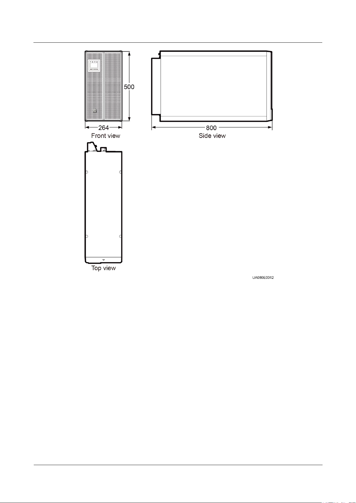
Dimensions
3 Installation
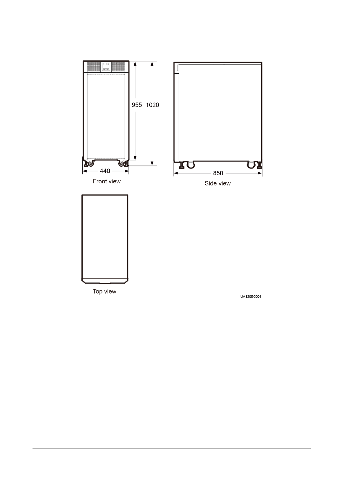
Figure 3-1 UPS5000-A-30 kVA/40 kVA installation dimensions (unit: mm)
Page 42
UPS5000-A-30 kVA & 40 kVA & 80 kVA
User Manual
3 Installation
Issue 11 (2018-12-10)
Copyright © Huawei Technologies Co., Ltd.
33
Page 43
UPS5000-A-30 kVA & 40 kVA & 80 kVA
User Manual
3 Installation
Issue 11 (2018-12-10)
Copyright © Huawei Technologies Co., Ltd.
34
Figure 3-2 UPS5000-A-80 kVA installation dimensions (unit: mm)
Installation Environment
Do not install the UPS in high temperature, low temperature, and damp areas. For details
about environmental specifications.
Install the UPS far away from water sources, heat sources, and inflammable or explosive
materials. Keep the UPS free from direct sunlight, dust, volatile gases, corrosive
materials, and salty air.
Do not install the UPS in environments with conductive metal scraps in the air.
The optimal operating temperatures for valve regulated lead acid (VRLA) batteries are
20–30°C. Operating temperatures higher than 30°C shorten the battery lifespan, and
operating temperatures lower than 20°C reduce the battery backup time.
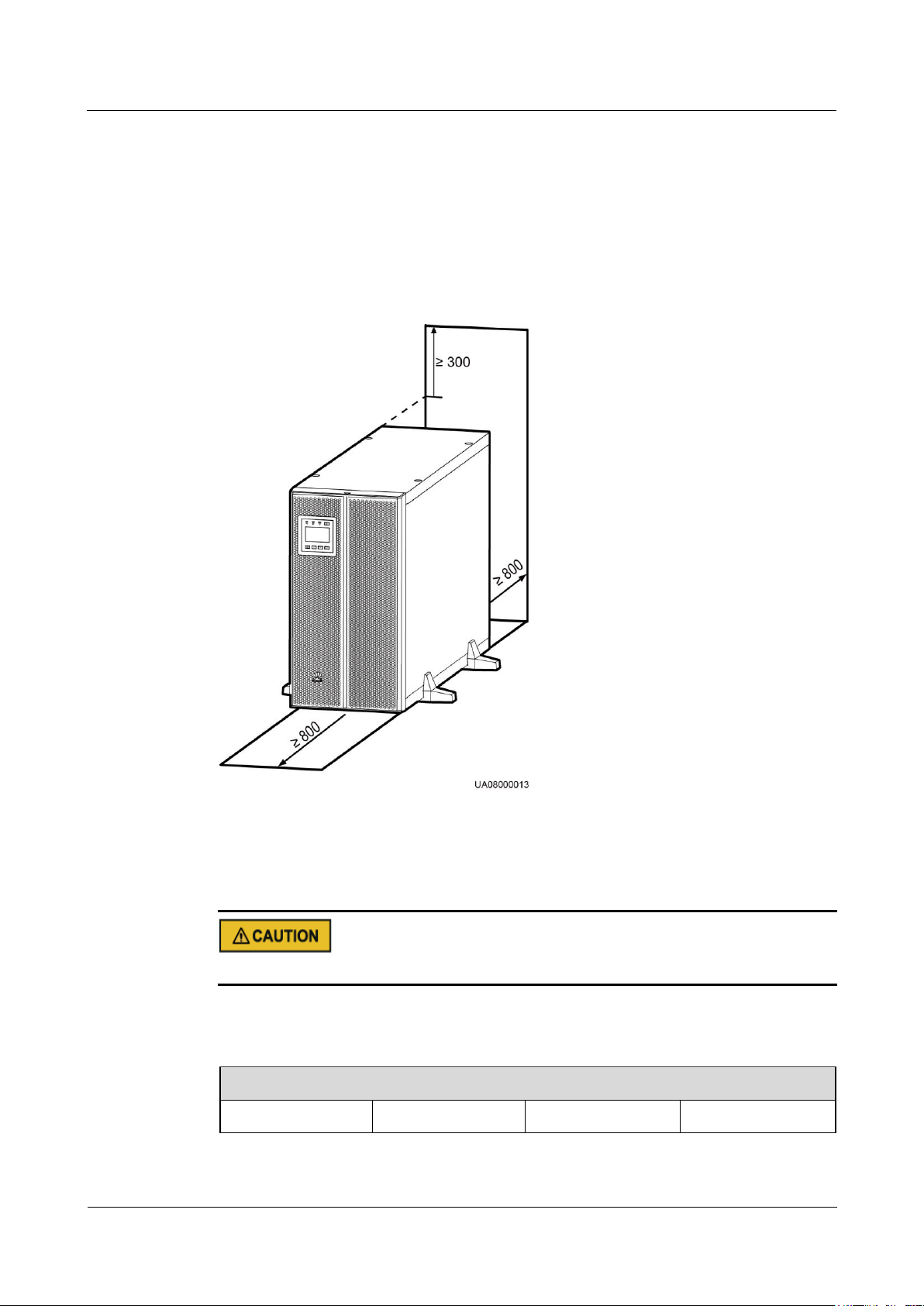
Installation Clearances
Reserve sufficient clearances around the cabinet for operations and ventilation:
Page 44
UPS5000-A-30 kVA & 40 kVA & 80 kVA
User Manual
3 Installation
Issue 11 (2018-12-10)
Copyright © Huawei Technologies Co., Ltd.
35
Tools and Meters
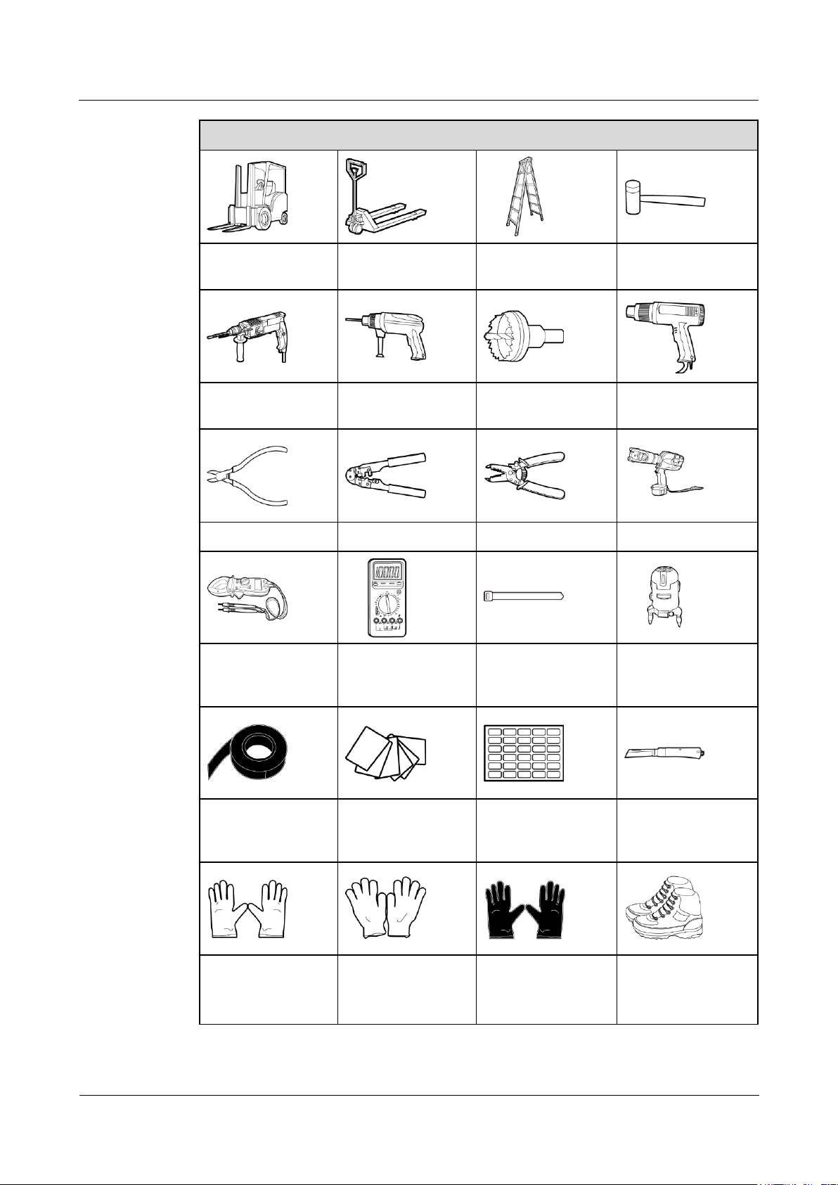
Electric pallet truck
Manual pallet truck
Ladder
Rubber mallet
Reserve a clearance of at least 800 mm on the front of the cabinet.
Reserve a clearance of at least 300 mm on the top of the cabinet.
Keep a clearance of at least 300 mm at the rear of the cabinet. If you need to perform
operations at the rear of the cabinet, keep a clearance of at least 800 mm.
Figure 3-3 takes the UPS5000-A-30 kVA/40 kVA as an example to show the installation
clearance.
Figure 3-3 Installation clearances (unit: mm)
3.1.2 Tools and Instruments
Insulate installation tools to prevent electric shocks.
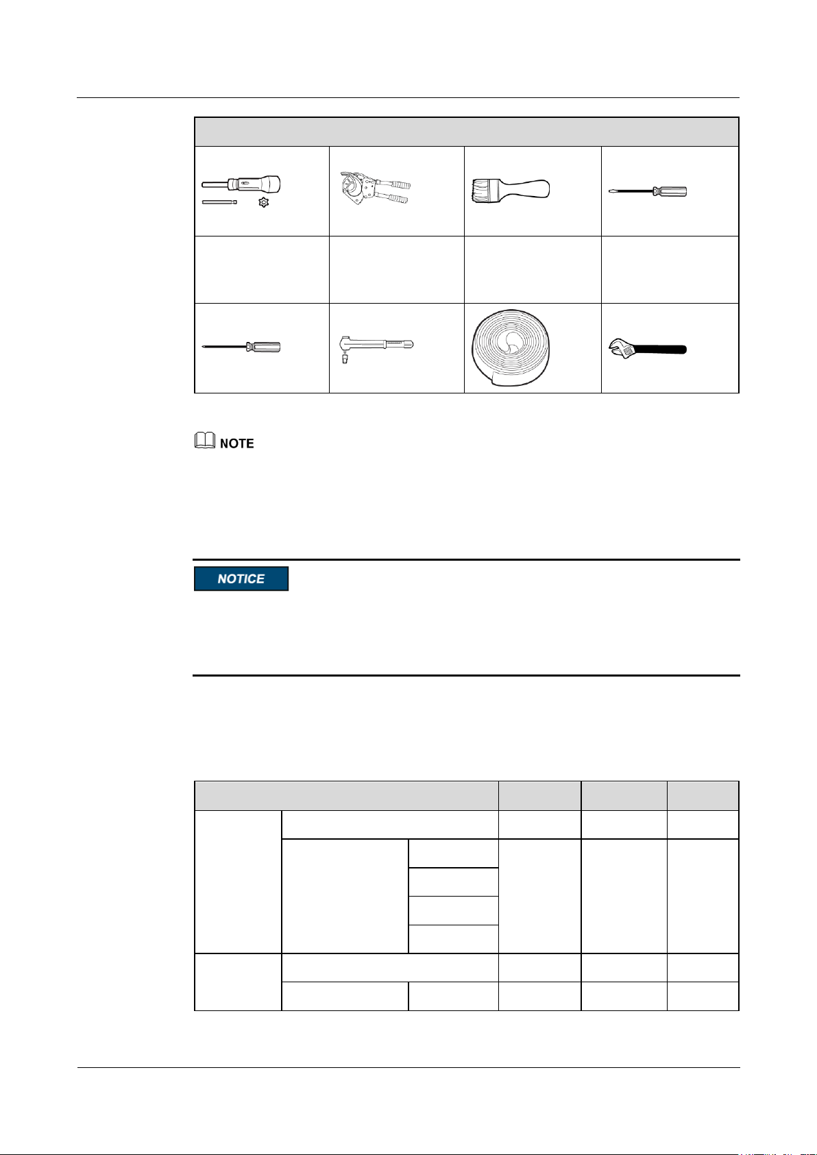
Prepare the following tools and meters indicated in Table 3-1 for installation.
Table 3-1 Tools and meters
Page 45
UPS5000-A-30 kVA & 40 kVA & 80 kVA
User Manual
3 Installation
Issue 11 (2018-12-10)
Copyright © Huawei Technologies Co., Ltd.
36
Tools and Meters
Hammer drill and
drill bit Φ16
Hand-held electric
drill
Alloy hole saw
Heat gun
Diagonal pliers
Crimping tools
Wire stripper
Electric hydraulic
pliers
Clamp meter
Multimeter
Cable tie
Level instrument
Polyvinyl chloride
(PVC) insulation
tape
Cotton cloth
Label
Electrician's knife
Electrostatic
discharge (ESD)
gloves
Protective gloves
Insulated gloves
Insulation protective
shoes
Torque screwdriver
Cable cutter
Brush
Flat-head
screwdriver
(2–5 mm)
Page 46
UPS5000-A-30 kVA & 40 kVA & 80 kVA
User Manual
3 Installation
Issue 11 (2018-12-10)
Copyright © Huawei Technologies Co., Ltd.
37
Tools and Meters
Phillips screwdriver
(M3/M4/M5/M6/M
8)
Insulated torque
wrench
(M6/M8/M12/M16)
Heat shrink tubing
Insulated adjustable
wrench
Item
30 kVA
40 kVA
80 kVA
Mains input
Mains input current (A)
53
71
142
Recommended
cross-sectional
area (mm2)
L1
4 x 10
4 x 16
4 x 50
L2
L3
N
Bypass
input
Bypass input current (A)
46
61
122
Recommended
L1
4 x 10
4 x 16
4 x 35
Table 3-1 lists only the common tools for installation and cable connection. For more dedicated tools
required, see the corresponding component manuals. Prepare tools based on site requirements.
3.1.3 Power Cables
The UPS can generate large leakage currents. A circuit breaker that provides leakage
current protection is not recommended.
If UPSs are connected in parallel, input and output power cables for each UPS should have
the same length and specifications.
Table 3-2 lists the recommended cross-sectional areas for power cables. Table 3-3 lists the
requirements for power cable connectors. Table 3-7 lists the recommended UPS input switch
configurations.
Table 3-2 Recommended cross-sectional areas for power cables
Page 47

UPS5000-A-30 kVA & 40 kVA & 80 kVA
User Manual
3 Installation
Issue 11 (2018-12-10)
Copyright © Huawei Technologies Co., Ltd.
38
Item
30 kVA
40 kVA
80 kVA
cross-sectional
area (mm2)
L2
L3
N
Output
Output current (A)
46
61
122
Recommended
cross-sectional
area (mm2)
U
4 x 10
4 x 16
4 x 35
V
W
N (Increase
the
cross-sectio
nal area at
non-linear
load)
Battery
input
Nominal discharge current (384 V
voltage; thirty-two 12 V batteries)
(A)
82
110
219
Maximum discharge current (end
of discharge current of thirty-two
12 V batteries, namely, 1.67 V/cell
discharge current of 192 2 V cells)
(A)
98
131
262
Recommended
cross-sectional
area (mm2)
+
3 x 16
3 x 35
3 x 95
N
–
Ground
cable
Recommended
cross-sectional
area (mm2)
PE
1 x 10
1 x 16
1 x 25
When the mains input and bypass input share a power source, configure input power cables as mains
input power cables. The cables listed in Table 3-2 are used only when the following requirements are
met:
The cables are installed along the wall or on the floor (IEC-60364-5-52 C standards).
The ambient temperature is 30ºC.
The AC voltage loss is less than 3%, and the DC voltage loss is less than 1%. The recommended
cable diameters in Table 3-2 meet the basic through-current requirements. Users should evaluate the
line voltage loss based on the actual cable length. If the voltage loss exceeds the requirements,
increase the cable diameter properly.
90°C copper cables are used.
If external conditions such as cable layout or ambient temperatures change, perform verification in
accordance with the IEC-60364-5-52 or local regulations.
When selecting, connecting, and routing power cables, follow local safety regulations and rules.
Page 48
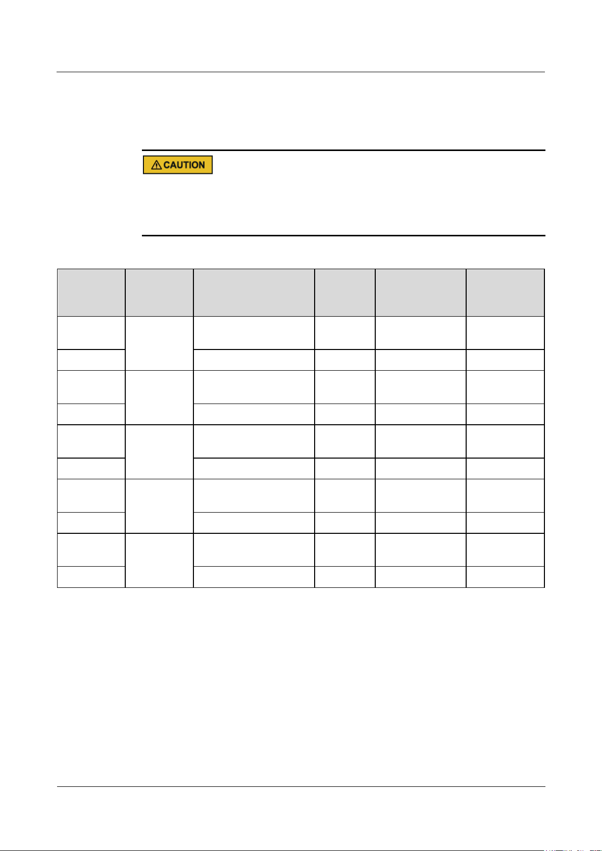
UPS5000-A-30 kVA & 40 kVA & 80 kVA
User Manual
3 Installation
Issue 11 (2018-12-10)
Copyright © Huawei Technologies Co., Ltd.
39
The currents listed in Table 3-2 are measured at a rated voltage of 380 V; if the rated voltage is 400 V,
Model
Connector
Connection Mode
Bolt
Specificat
ions
Bolt Hole
Diameter
Torque
30 kVA-40
kVA
Mains input
connectors
Crimped OT terminal
M6
6.5 mm
4.5 N·m
80 kVA
Crimped DT terminal
M8
9 mm
13 N·m
30 kVA-40
kVA
Bypass input
connectors
Crimped OT terminals
M6
6.5 mm
4.5 N•m
80 kVA
Crimped DT terminal
M8
9 mm
13 N•m
30 kVA-40
kVA
Battery input
connectors
Crimped OT terminal
M8
9 mm
13 N•m
80 kVA
Crimped DT terminal
M10
11 mm
27 N•m
30 kVA-40
kVA
Output
connectors
Crimped OT terminal
M6
6.5 mm
4.5 N•m
80 kVA
Crimped DT terminal
M8
9 mm
13 N•m
30 kVA-40
kVA
Grounding
connectors
Crimped OT terminal
M6
6.5 mm
4.5 N•m
80 kVA
Crimped DT terminal
M8
9 mm
27 N•m
multiply the currents by 0.95; if the rated voltage is 415 V, multiply the currents by 0.92.
If primary loads are non-linear loads, increase the cross-sectional areas of neutral wires 1.5–1.7 times.
Use OT or DT terminals of the specifications listed in Table 3-3, Table 3-4, and Table 3-5 to
prevent short circuits.
When you connect power cables, comply with the tightening torque listed in Table 3-3 to
ensure secure connections and prevent safety risks.
Table 3-3 Power cable connector requirements
Page 49
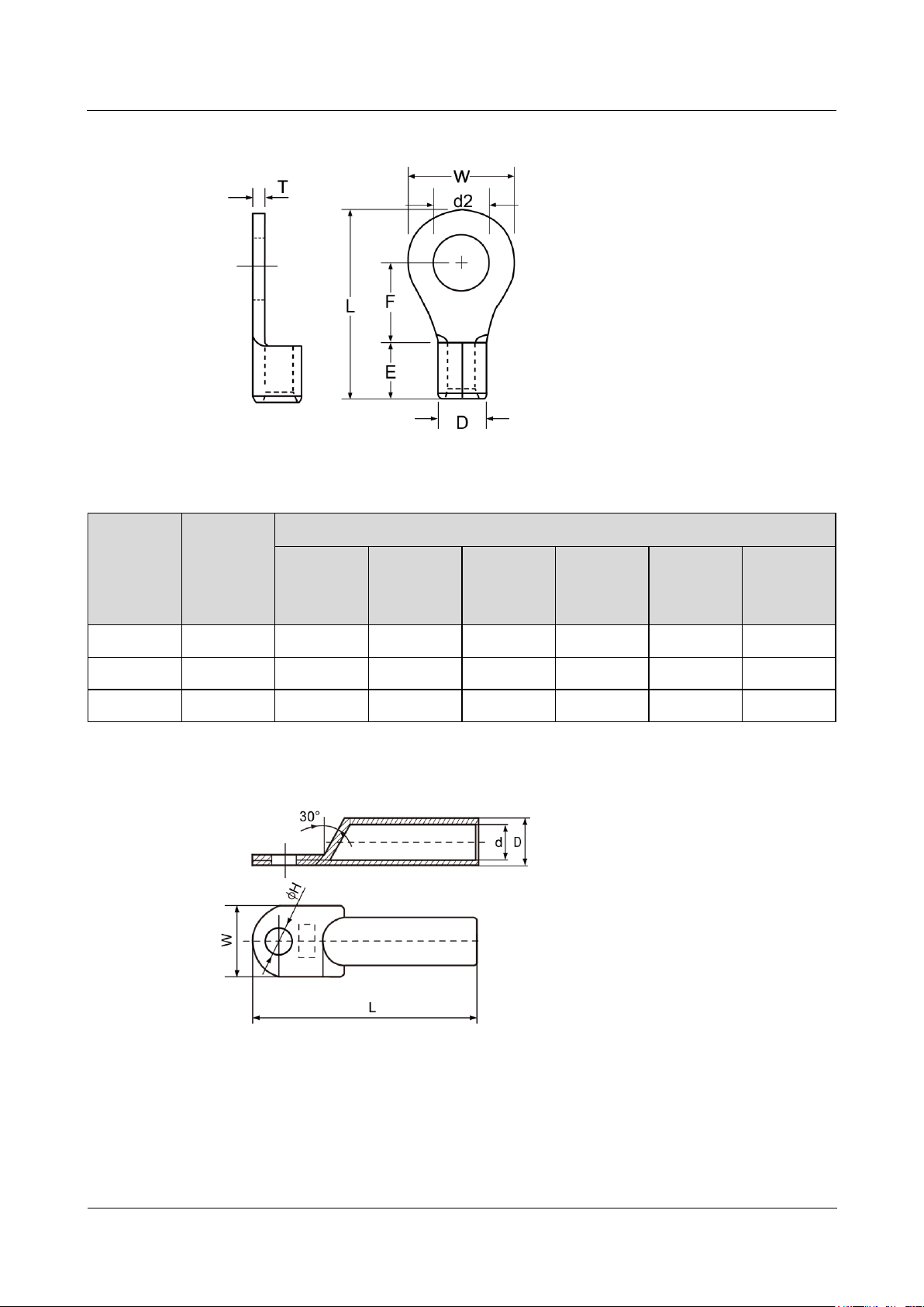
UPS5000-A-30 kVA & 40 kVA & 80 kVA
User Manual
3 Installation
Issue 11 (2018-12-10)
Copyright © Huawei Technologies Co., Ltd.
40
Figure 3-4 OT terminal for the UPS5000-A
Nominal
conductor
cross-secti
onal area
(mm2)
OT
terminal
hole
diameter
d2 (mm)
Dimensions (mm)
W F L E D
T
10
6.4±0.2
12.0±0.2
9.3±0.2
23.8±0.3
8.5±0.2
7.0
1.25±0.1
16
6.4±0.2
12.0±0.2
13.3±0.2
29.8±0.3
10.5±0.2
9.0
1.5±0.1
35
9±0.2
22.0±0.2
16.0±0.2
41.0±0.3
14.0±0.2
13.3
1.8±0.1
Table 3-4 OT terminal specifications for the UPS5000-A
Figure 3-5 DT terminal for the UPS5000-A
Page 50
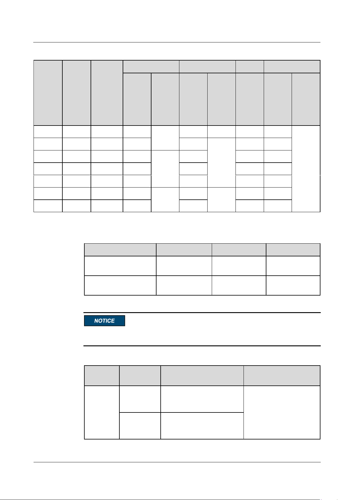
UPS5000-A-30 kVA & 40 kVA & 80 kVA
User Manual
3 Installation
Issue 11 (2018-12-10)
Copyright © Huawei Technologies Co., Ltd.
41
Table 3-5 DT terminal specifications for the UPS5000-A
Nomin
al
conduc
tor
cross-s
ectiona
l area
(mm2)
Bolt
diamet
er
(mm)
ΦH
(mm)
d(mm)
D(mm)
W(mm)
L(mm)
Nomin
al
value
Deviati
on
Nomin
al
value
Deviati
on
Refere
nce
value
Nomin
al
value
Deviation
25 6 6.5
7
±0.30
10
0–0.12
14
60
±1.50
35 8 8.4
8.5
12
0–0.16
16
66
50 8 8.4
10
±0.40
14
19
72
70
10
10.5
12
16
22
80
95
10
10.5
13
18
25
87
120
12
13
15
±0.50
20
0–0.24
28
96
150
12
13
16
22
32
103
Circuit Breaker
30 kVA
40 kVA
80 kVA
Mains input front-end
circuit breaker
80A/3P
100A/3P
160A/3P
Bypass input front-end
circuit breaker
80A/3P
100A/3P
160A/3P
UPS
Capacity
Component
Specifications
Manufacturer
30 kVA
Mains input
circuit
breaker
T1N160 TMD R80 FFC 3P
ABB (recommended when
the short-circuit current of
the circuit breaker is
located is less than 36 kA.)
Bypass input
circuit
breaker
T1N160 TMD R80 FFC 3P
Table 3-6 Input front-end circuit breaker configurations
The UPS can generate large leakage currents. A circuit breaker that provides leakage current
protection is not recommended.
Table 3-7 Recommended input front-end and output back-end circuit breakers
Page 51

UPS5000-A-30 kVA & 40 kVA & 80 kVA
User Manual
3 Installation
Issue 11 (2018-12-10)
Copyright © Huawei Technologies Co., Ltd.
42
UPS
Capacity
Component
Specifications
Manufacturer
40 kVA
Mains input
circuit
breaker
T1N160 TMD R100 FFC 3P
Bypass input
circuit
breaker
T1N160 TMD R100 FFC 3P
80 kVA
Mains input
circuit
breaker
T1N160 TMD R160 3P FFC
Bypass input
circuit
breaker
T1N160 TMD R160 3P FFC
30 kVA
Output
branch circuit
breaker
S203 C50
ABB (recommended when
the short-circuit current of
the circuit breaker is
located is less than 6 kA.)
40 kVA
S203 C63
80 kVA
T1N160 TMD R125 3P FFC
ABB (recommended when
the short-circuit current of
the circuit breaker is
located is less than 36 kA.)
The input front-end and output back-end circuit breakers recommended in Table 3-7 are for
reference only.
If multiple loads are connected, branch circuit breaker specifications must not exceed the
recommended specifications.
The circuit breaker selection principle is to protect loads and cables, and the cascading principle is to
realize specific protection.
3.1.4 Unpacking and Checking
Page 52
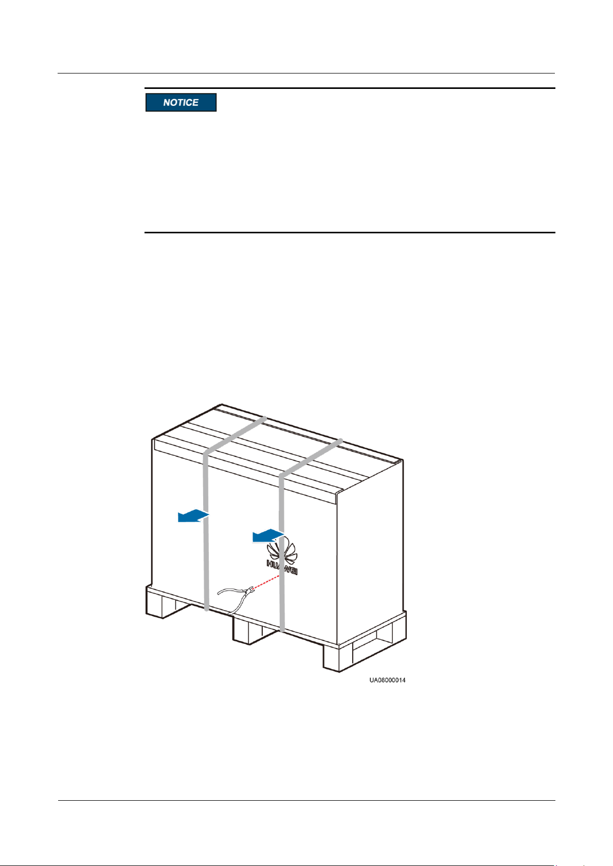
UPS5000-A-30 kVA & 40 kVA & 80 kVA
User Manual
3 Installation
Issue 11 (2018-12-10)
Copyright © Huawei Technologies Co., Ltd.
43
Only trained personnel are allowed to move the UPS. Use a pallet truck to transport the
UPS box secured to a wooden support to the installation position.
To prevent the UPS from falling over, secure it to a pallet truck using ropes before moving
it.
To prevent shocks or falls, move the UPS gently. Unpack it and take care to prevent
scratches. Keep the UPS steady during unpacking.
If the UPS installation environment is in poor condition and the UPS will be stored for a
long time after it is unpacked, wrap the UPS with the original plastic coat to prevent dust.
3.1.4.1 30 kVA/40 kVA UPS
Procedure
Step 1 Visually inspect the UPS appearance for shipping damage. If any shipping damage is founded,
report it to the carrier immediately.
Step 2 Use a pallet truck to transport the UPS to the installation position.
Step 3 Cut and remove the binding tape, as shown in Figure 3-6.
Figure 3-6 Removing binding tape
Step 4 Remove packing materials, as shown in Figure 3-7.
Page 53
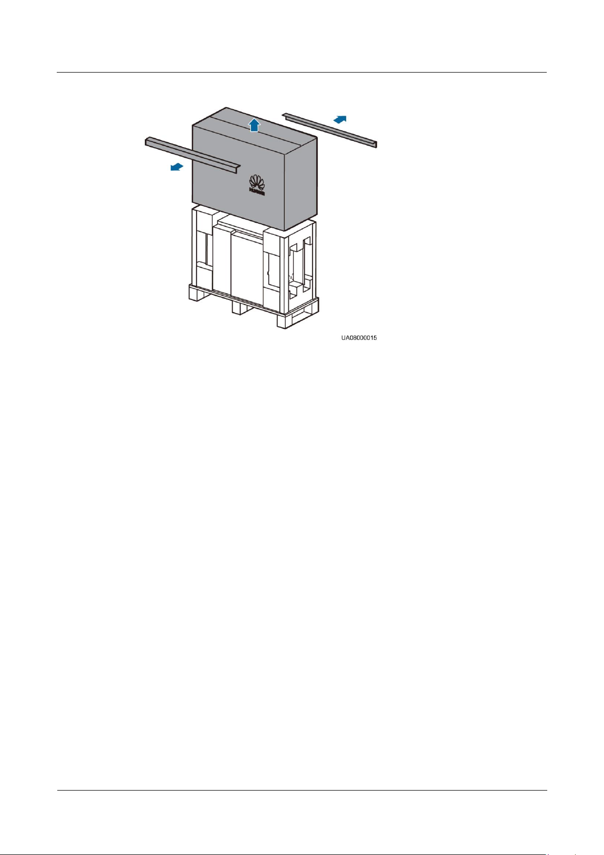
UPS5000-A-30 kVA & 40 kVA & 80 kVA
User Manual
3 Installation
Issue 11 (2018-12-10)
Copyright © Huawei Technologies Co., Ltd.
44
Figure 3-7 Removing packing materials
Step 5 Remove the foam and moisture-proof bag, and take out the UPS.
Step 6 Check that the UPS is intact.
1. Visually inspect the UPS appearance for shipping damage. If it is damaged, notify the
carrier immediately.
2. Check that the fittings comply with the packing list. If some fittings are missing or do
not comply with the packing list, record the information and contact your local Huawei
office immediately.
Step 7 Place the UPS in the installation position.
----End
3.1.4.2 80 kVA UPS
Procedure
Step 1 Visually inspect the UPS appearance for shipping damage. If any shipping damage is founded,
report it to the carrier immediately.
Step 2 Use a pallet truck to transport the UPS to the installation position.
Step 3 Hold the sliding plate steadily, cut and remove the binding tape, and put down the sliding
plate gently, as shown in Figure 3-8.
Page 54
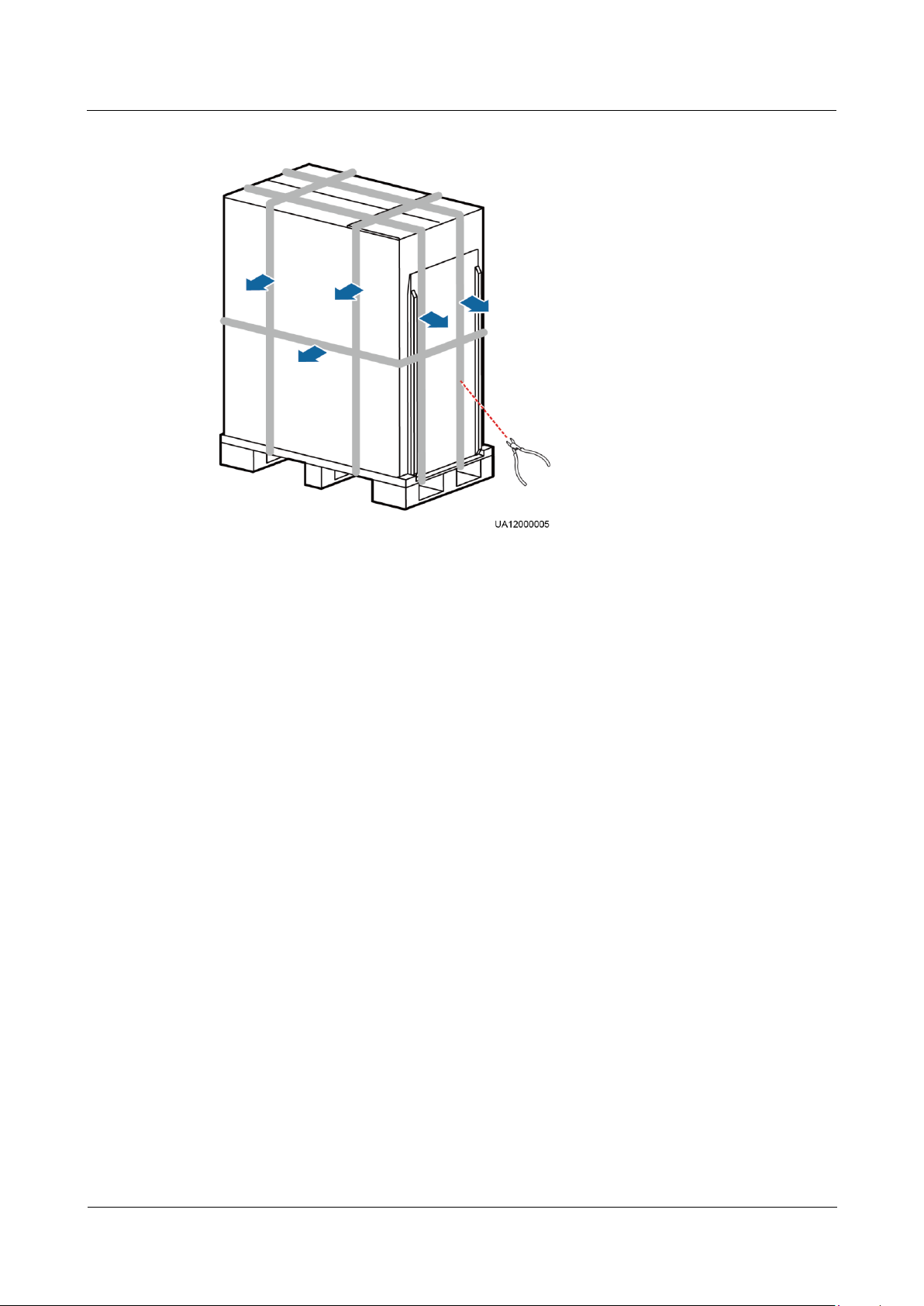
UPS5000-A-30 kVA & 40 kVA & 80 kVA
User Manual
3 Installation
Issue 11 (2018-12-10)
Copyright © Huawei Technologies Co., Ltd.
45
Figure 3-8 Removing binding tape
Step 4 Remove the packing materials and foam, as shown in Figure 3-9.
Page 55
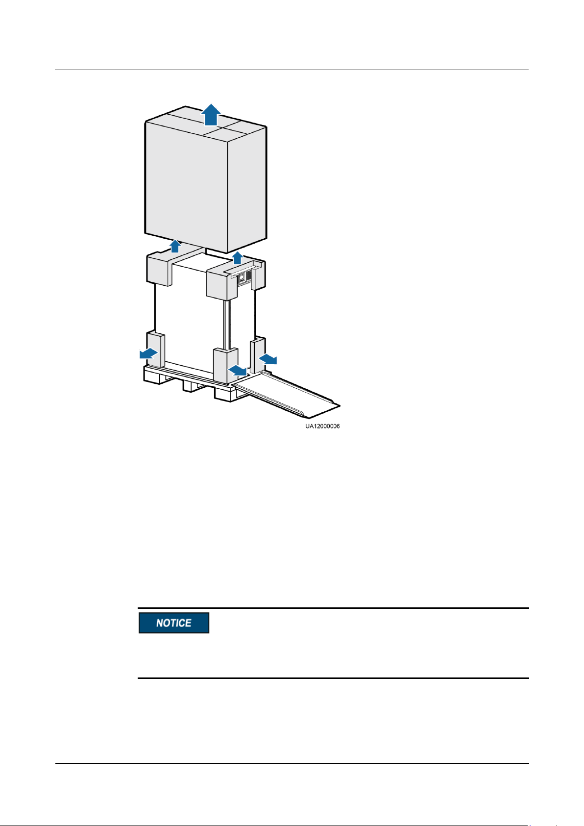
UPS5000-A-30 kVA & 40 kVA & 80 kVA
User Manual
3 Installation
Issue 11 (2018-12-10)
Copyright © Huawei Technologies Co., Ltd.
46
Figure 3-9 Removing packing materials
Step 5 Remove the moisture-proof bag.
Step 6 Check that the UPS is intact.
1. Visually inspect the UPS appearance for shipping damage. If any damage is founded,
notify the carrier immediately.
2. Check that the fittings comply with the packing list. If some fittings are missing or do
not comply with the packing list, record the information and contact your local Huawei
office immediately.
Step 7 Remove the UPS front panel, as shown in Figure 3-10.
Remove both the upper and lower front panels from the UPS. Removing the upper one
facilitates removal of L-shaped brackets. Removing the lower one prevents itself from falling
off during transportation.
Page 56
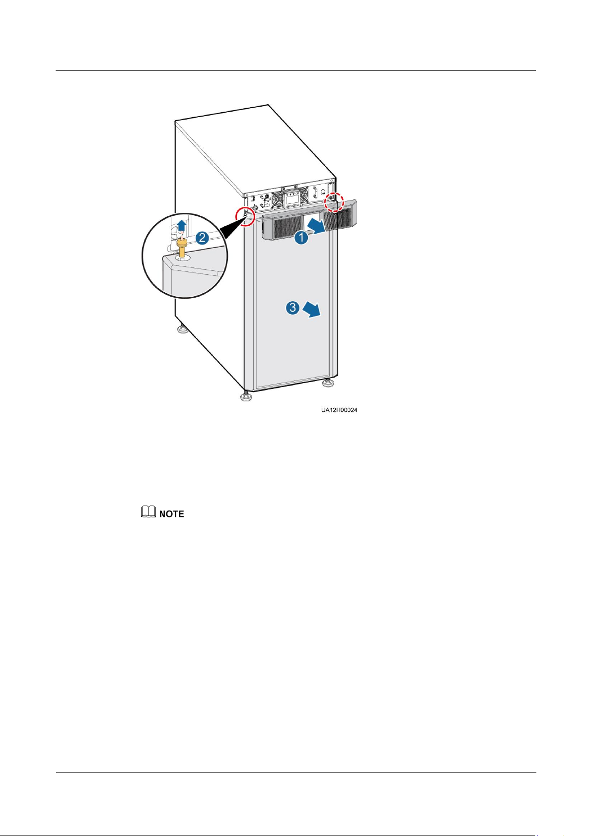
UPS5000-A-30 kVA & 40 kVA & 80 kVA
User Manual
3 Installation
Issue 11 (2018-12-10)
Copyright © Huawei Technologies Co., Ltd.
47
Figure 3-10 Removing UPS front panels
1. Press the button on both sides of UPS front panel 1.
2. Remove UPS front panel 1.
3. Remove the screws of UPS front panel 2.
4. Remove UPS front panel 2.
Before you remove the front panel 2, disconnect the ground cable connected to the chassis.
Step 8 Remove the L-shaped bracket that secures the chassis to the pallet, as shown in Figure 3-11.
Page 57
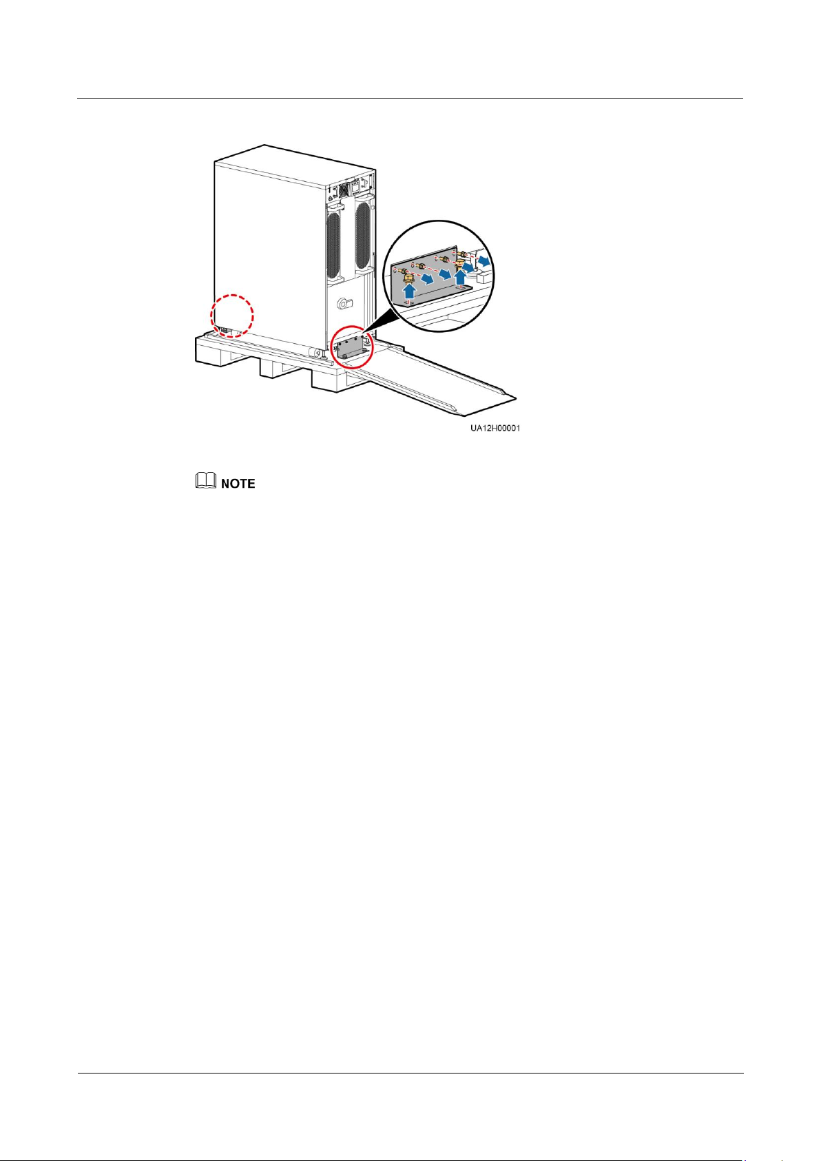
UPS5000-A-30 kVA & 40 kVA & 80 kVA
User Manual
3 Installation
Issue 11 (2018-12-10)
Copyright © Huawei Technologies Co., Ltd.
48
Figure 3-11 Removing the L-shaped bracket
Store the removed L-shaped bracket, which will be used to secure the UPS.
Step 9 Push the cabinet along the sliding plate to the installation position.
----End
3.2 Installing a Single UPS
3.2.1 Installing the UPS5000-A-30 kVA/40 kVA
Tower-mounting the UPS
Step 1 Assemble support bases. When you assemble two modules, snap the fasteners into the holes
to secure them, as shown in Figure 3-12.
Page 58
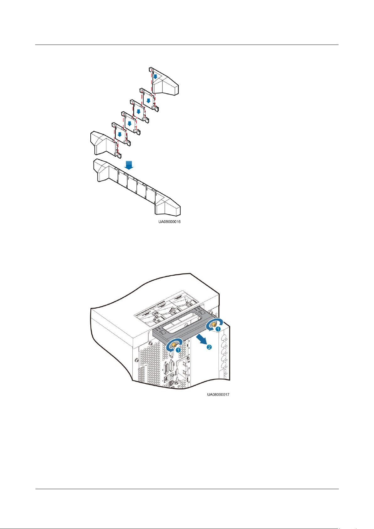
UPS5000-A-30 kVA & 40 kVA & 80 kVA
User Manual
3 Installation
Issue 11 (2018-12-10)
Copyright © Huawei Technologies Co., Ltd.
49
Figure 3-12 Assembling support bases
Step 2 Pull the back-end handle out of the UPS, as shown in Figure 3-13.
Figure 3-13 Pulling the back-end handle
1. Loosen the back-end handle screw s anticlockwise.
2. Pull the handle out of the groove.
Step 3 Hold the front-end handle and back-end handle to place the UPS on support bases. Each UPS
requires two pairs of support bases, and the distance between the two pairs of support bases
must be 480 mm or more, as shown in Figure 3-14.
Page 59
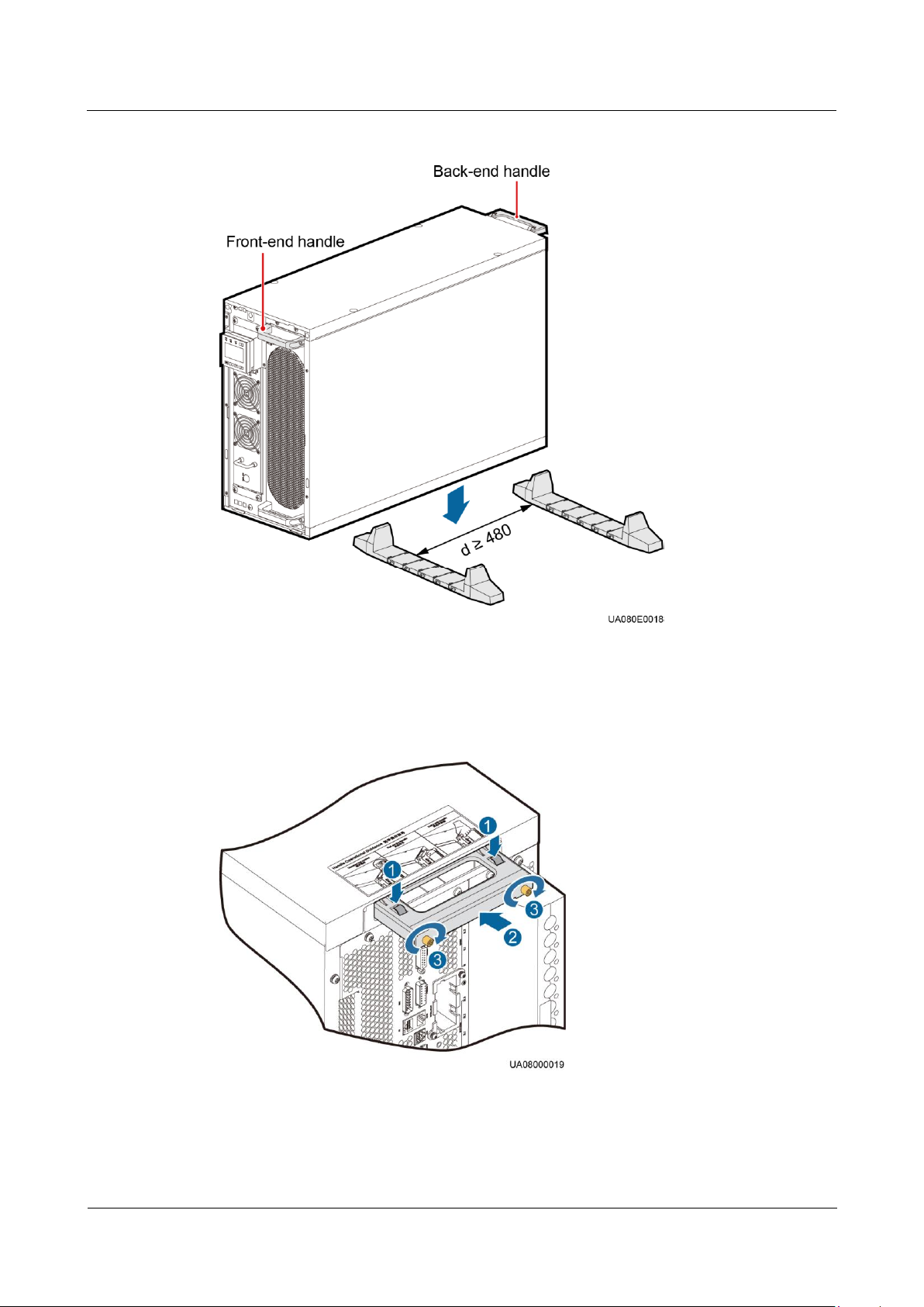
UPS5000-A-30 kVA & 40 kVA & 80 kVA
User Manual
3 Installation
Issue 11 (2018-12-10)
Copyright © Huawei Technologies Co., Ltd.
50
Figure 3-14 Placing the UPS on support bases (unit: mm)
Step 4 Push the back-end handle into the groove, as shown in Figure 3-15. For details, see the
instructions on the chassis.
Figure 3-15 Pushing the back-end handle into the groove
1. Press the back-end handle switch.
2. Push the handle into the groove.
Page 60
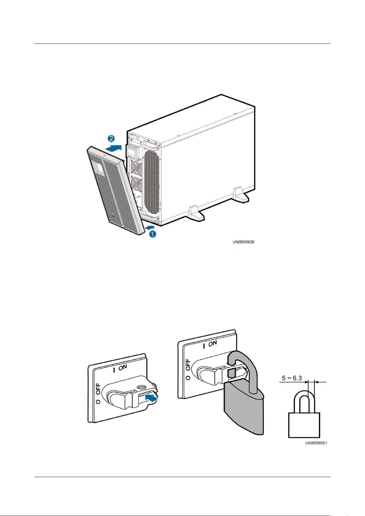
UPS5000-A-30 kVA & 40 kVA & 80 kVA
User Manual
3 Installation
Issue 11 (2018-12-10)
Copyright © Huawei Technologies Co., Ltd.
51
3. Tighten the screws clockwise to secure the handle.
Step 5 Install the front panel, as shown in Figure 3-16.
Figure 3-16 Installing the front panel
1. Insert the bottom half of the panel into the UPS.
2. Push the top half of the panel until it is securely fastened in place.
Step 6 (Recommended) Install a lock for the maintenance bypass switch to prevent misoperations, as
shown in Figure 3-17. The required lock core diameter is 5 mm to 6.3 mm.
Figure 3-17 Installing a lock for the maintenance bypass switch (unit: mm)
Page 61
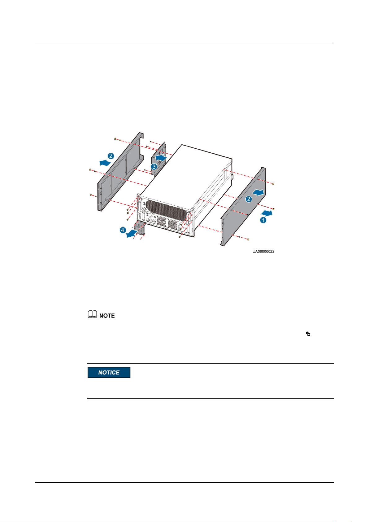
UPS5000-A-30 kVA & 40 kVA & 80 kVA
User Manual
3 Installation
Issue 11 (2018-12-10)
Copyright © Huawei Technologies Co., Ltd.
52
----End
Rack-mounting the UPS
Step 1 Remove the left and right side panels, handles, and MDU from the UPS chassis, as shown in
Figure 3-18. Before you remove the MDU, remove the cables that are connected to the
chassis.
Figure 3-18 Removing the left and right side panels, handles, and MDU from the UPS chassis
1. Remove the rubber plug from the chassis.
2. Remove the left and right side panels.
3. Remove the handle.
4. Remove the MDU.
Before you remove the side panels, unscrew the mounting ear of the power unit.
Step 2 Place the ready switches on the power unit and bypass unit into the unlocked state , and
remove the power unit and bypass unit, as shown in Figure 3-19.
Two persons are required to move a power unit. During movement, keep the power unit and
bypass unit always in a horizontal direction.
Page 62
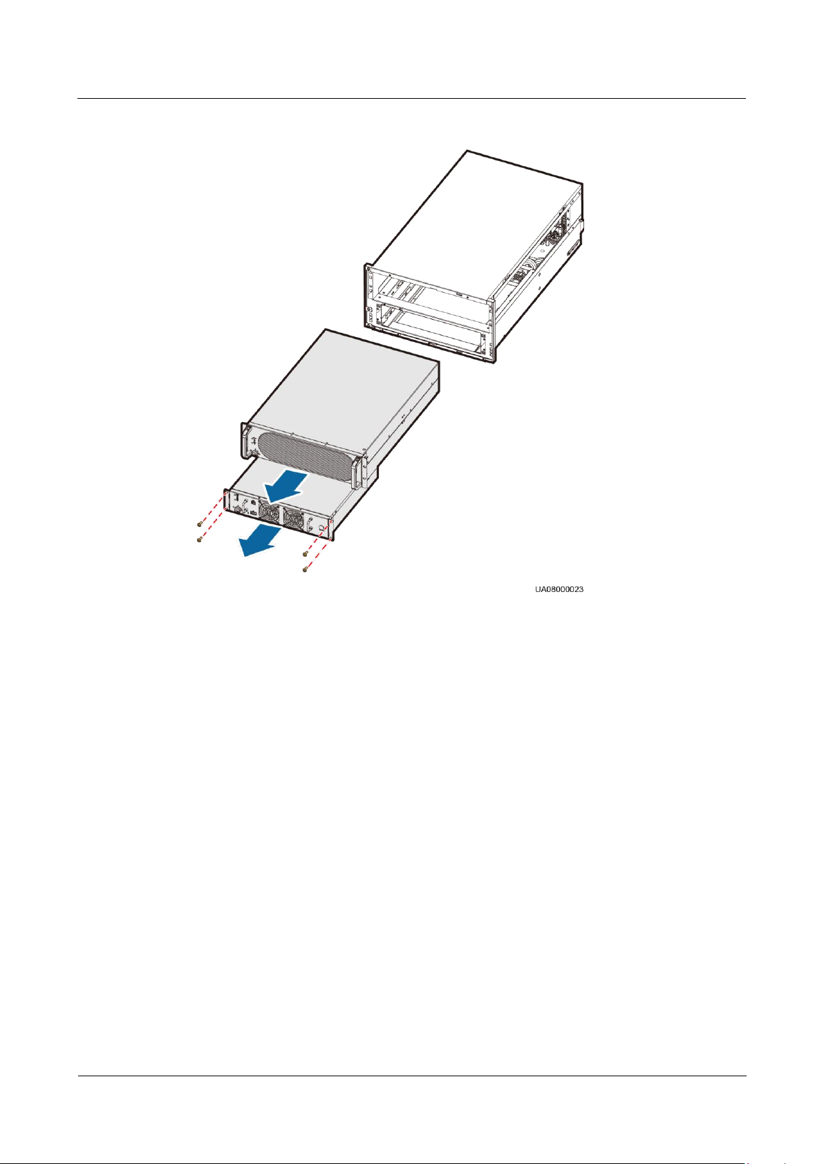
UPS5000-A-30 kVA & 40 kVA & 80 kVA
User Manual
3 Installation
Issue 11 (2018-12-10)
Copyright © Huawei Technologies Co., Ltd.
53
Figure 3-19 Removing the power unit and bypass unit
Step 3 Install guide rails (2 U) on the cabinet.
1. Align the lower edge of a guide rail with the lower edge of a U scale, and then engage
the mounting brackets on both ends of the guide rail into the mounting holes, as shown
in Figure 3-20.
Page 63
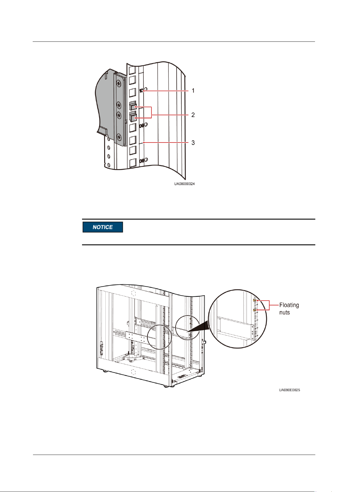
UPS5000-A-30 kVA & 40 kVA & 80 kVA
User Manual
3 Installation
Issue 11 (2018-12-10)
Copyright © Huawei Technologies Co., Ltd.
54
Figure 3-20 Engaging the mounting brackets (rear view)
(1) Scale
(2) Mounting bracket
(3) Lower edge of a U scale
Ensure that the lower edge of the guide rail is aligned with the lower edge of a U scale.
2. Install floating nuts on the front of the guide rail, as shown in Figure 3-21. Figure 3-22
shows the installation method.
Figure 3-21 Installation positions of floating nuts
Page 64
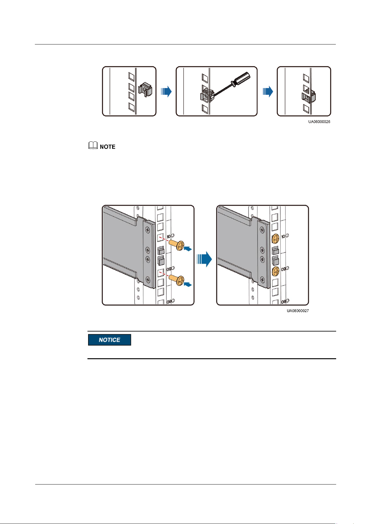
UPS5000-A-30 kVA & 40 kVA & 80 kVA
User Manual
3 Installation
Issue 11 (2018-12-10)
Copyright © Huawei Technologies Co., Ltd.
55
Figure 3-22 Installing floating nuts
Install floating nuts by using a flat-head screwdriver.
3. Secure the back end of the guide rail with panel screws, as shown in Figure 3-23. Do not
install panel screws on the front end of the guide rail. Use the same method to install the
other guide rail.
Figure 3-23 Securing the back end of the guide rail (rear view)
In this step, secure only the back end of the guide rail.
Step 4 Insert the subrack into the cabinet, as shown in Figure 3-24. Then secure the front end of the
guide rail with panel screws.
Page 65
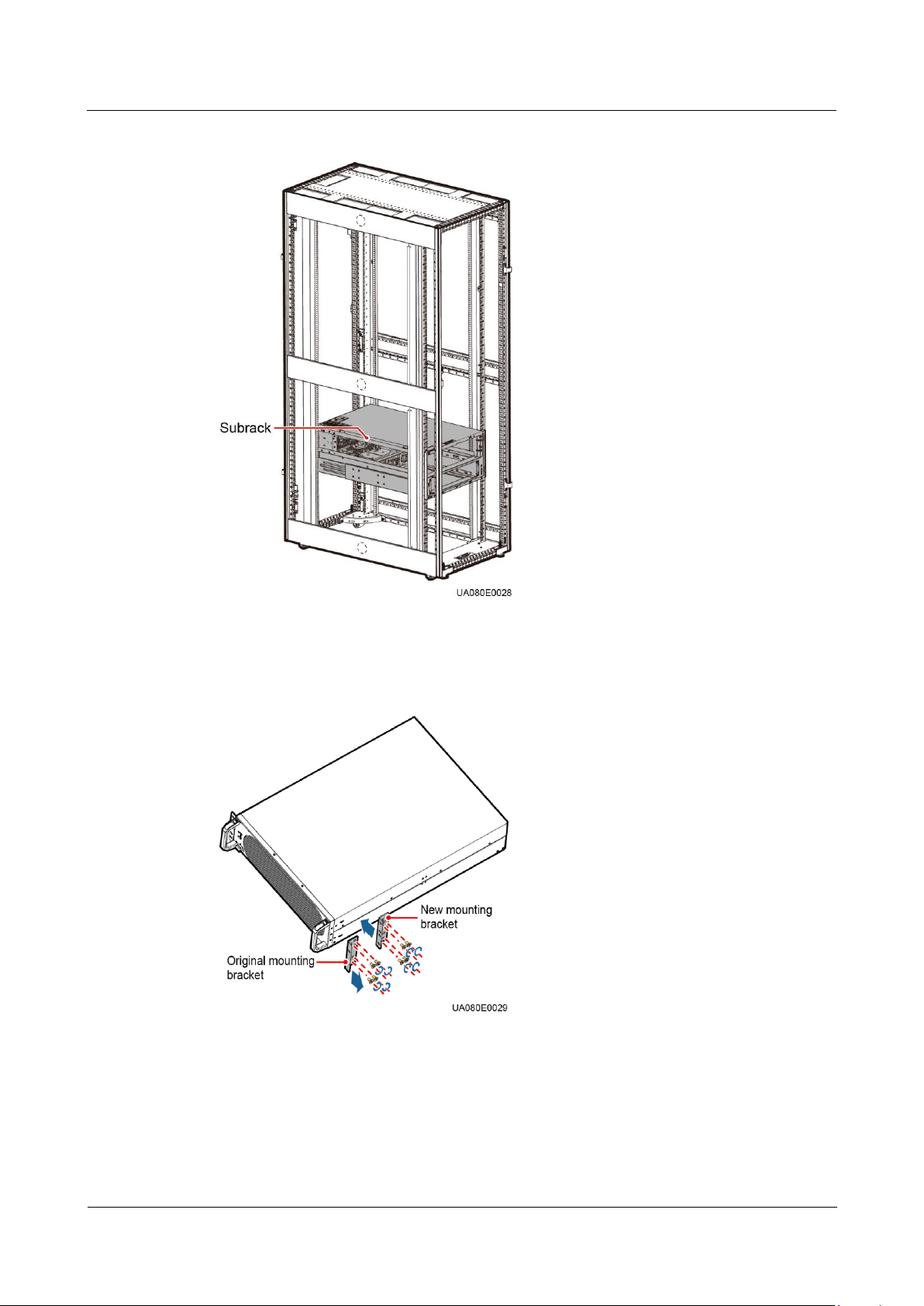
UPS5000-A-30 kVA & 40 kVA & 80 kVA
User Manual
3 Installation
Issue 11 (2018-12-10)
Copyright © Huawei Technologies Co., Ltd.
56
Figure 3-24 The position of the subrack
Step 5 Replace the left and right mounting brackets for the power unit, as shown in Figure 3-25.
Figure 3-25 Replacing a mounting bracket
Step 6 Insert the power unit and bypass unit into the subrack, and secure them with screws, as shown
in Figure 3-26.
Page 66
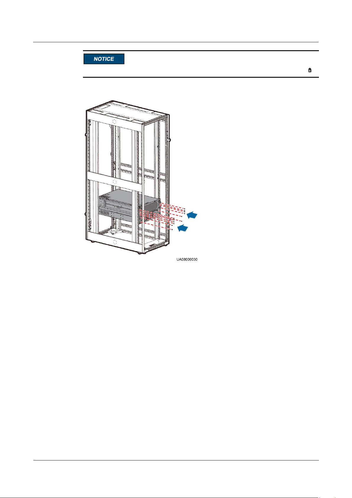
UPS5000-A-30 kVA & 40 kVA & 80 kVA
User Manual
3 Installation
Issue 11 (2018-12-10)
Copyright © Huawei Technologies Co., Ltd.
57
After you insert the power unit and bypass unit, rotate the ready switches to locked state .
Figure 3-26 Fixing the power unit and bypass unit
Step 7 Rotate the MDU (removed in Step 1) clockwise 90 degrees, install it along with the support,
and connect cables, as shown in Figure 3-27.
Page 67
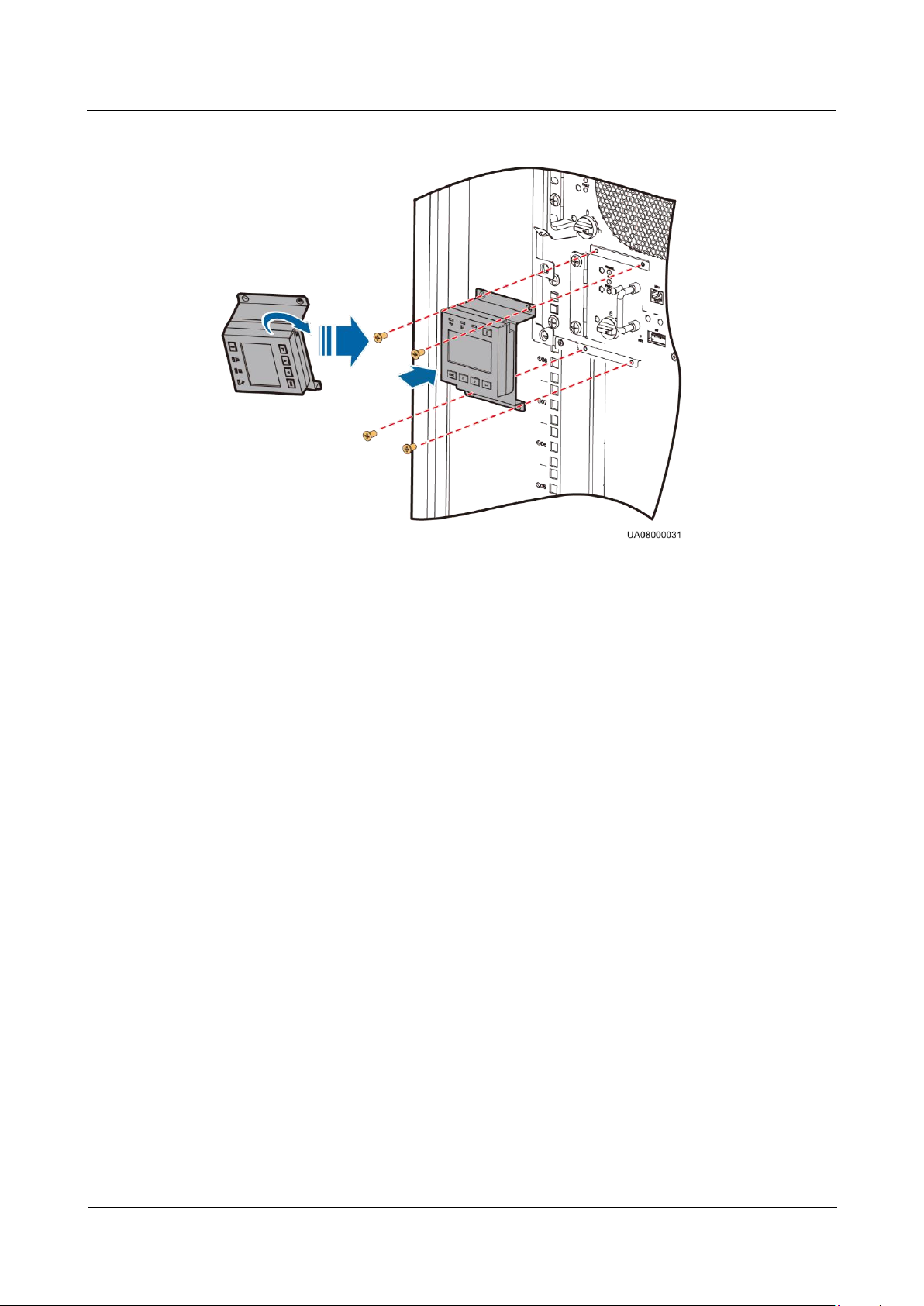
UPS5000-A-30 kVA & 40 kVA & 80 kVA
User Manual
3 Installation
Issue 11 (2018-12-10)
Copyright © Huawei Technologies Co., Ltd.
58
Figure 3-27 Installing the MDU
Step 8 Install the front panel and rotate the Huawei logo on it clockwise 90 degrees, as shown in
Figure 3-28.
Page 68
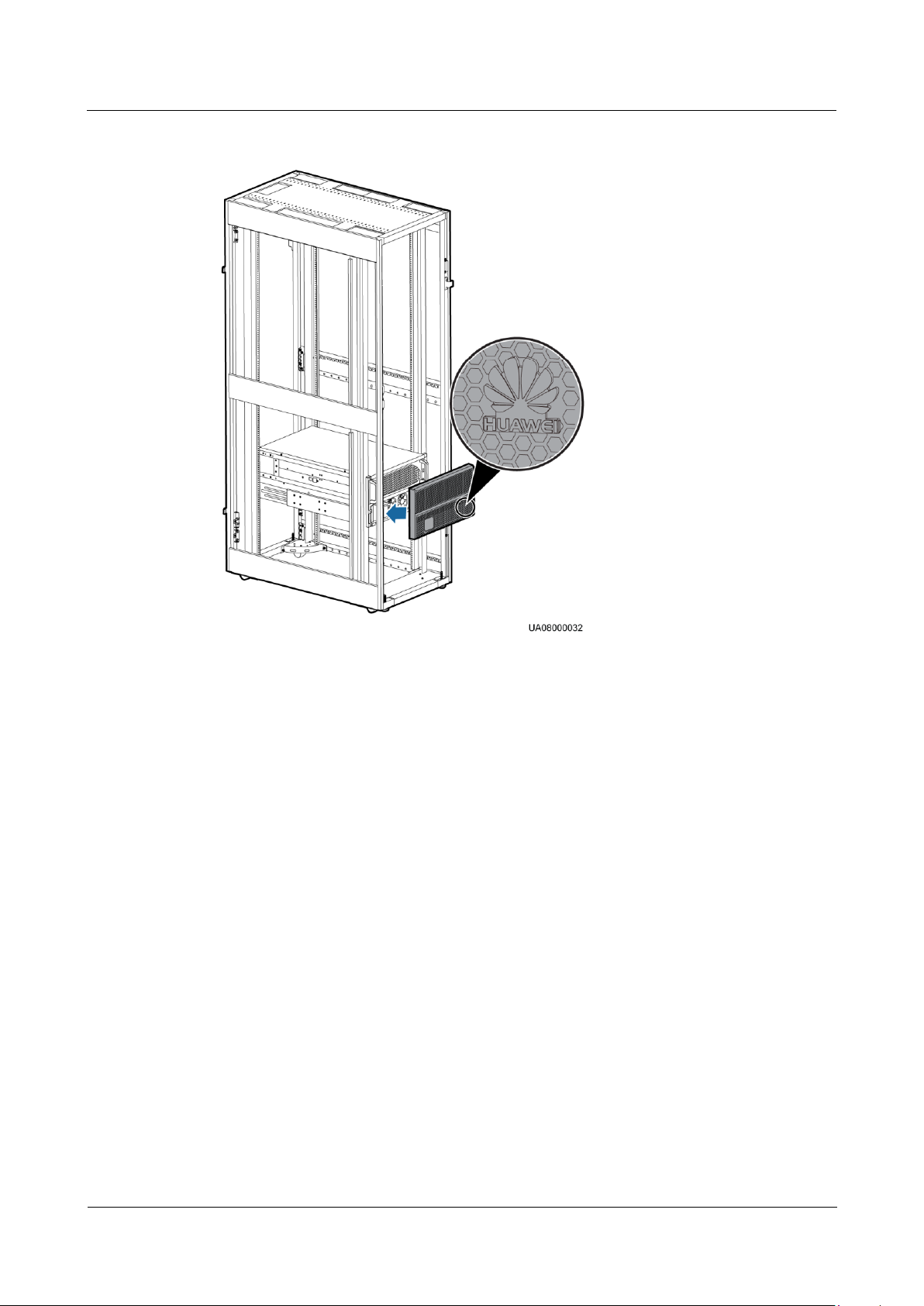
UPS5000-A-30 kVA & 40 kVA & 80 kVA
User Manual
3 Installation
Issue 11 (2018-12-10)
Copyright © Huawei Technologies Co., Ltd.
59
Figure 3-28 Installing the front panel
Step 9 (Recommended) Install a lock for the maintenance bypass switch, as shown in Figure 3-17.
----End
3.2.2 Installing the UPS5000-A-80 kVA
Installing a UPS by Using Leveling Feet
Step 1 Lower the four leveling feet at the bottom of the cabinet using a wrench until all the four
castors at the bottom hang in the air and the leveling feet bear the whole cabinet weight, as
shown in Figure 3-29.
Page 69
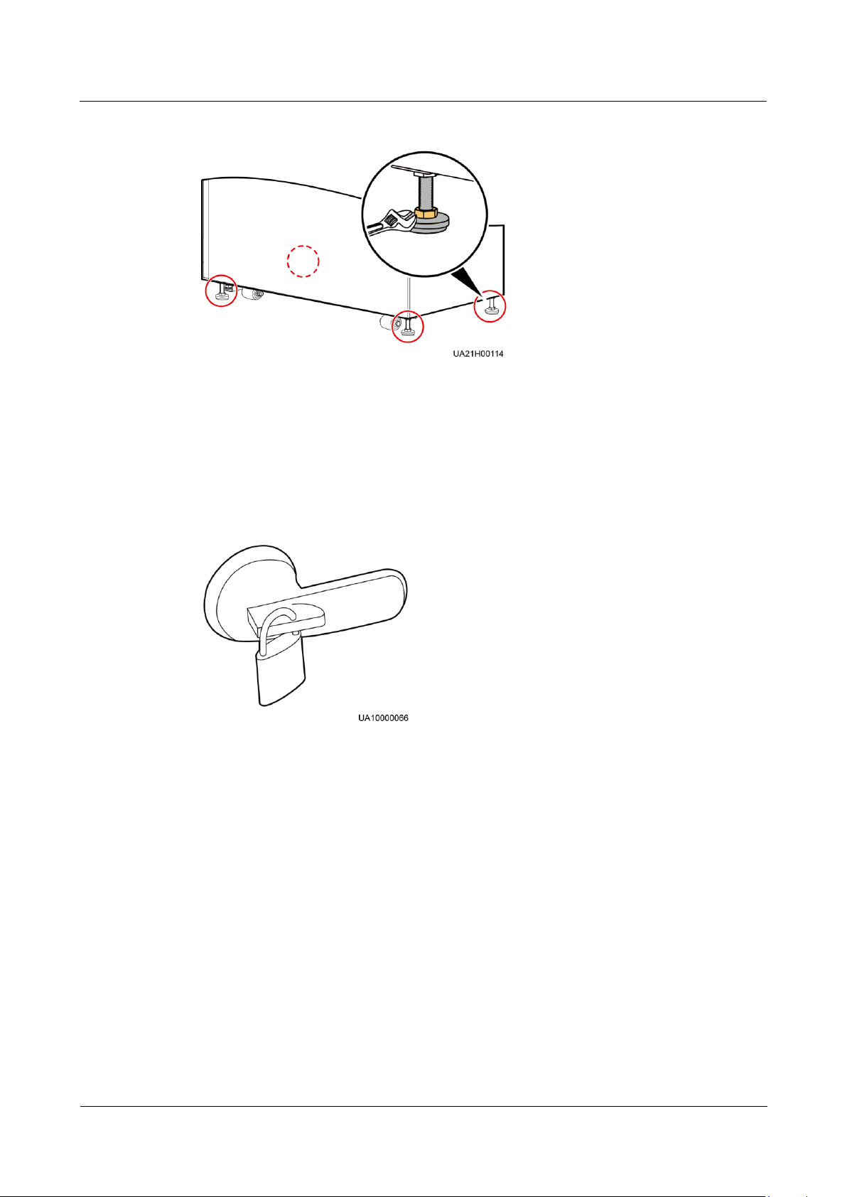
UPS5000-A-30 kVA & 40 kVA & 80 kVA
User Manual
3 Installation
Issue 11 (2018-12-10)
Copyright © Huawei Technologies Co., Ltd.
60
Figure 3-29 Lowering the leveling feet
Step 2 Check the cabinet levelness using a level. If the cabinet is not leveled, adjust the leveling feet.
Step 3 Reinstall the upper and lower front panels.
Step 4 (Recommended) Install a lock for the maintenance bypass switch to prevent misoperations, as
shown in Figure 3-30. The required lock core diameter is 5–10 mm.
Figure 3-30 Lock for the maintenance bypass switch
----End
Installing a UPS by Using L-shape Brackets
Step 1 Determine the position for installing the UPS and mark mounting holes, as shown in Figure
3-31.
Page 70
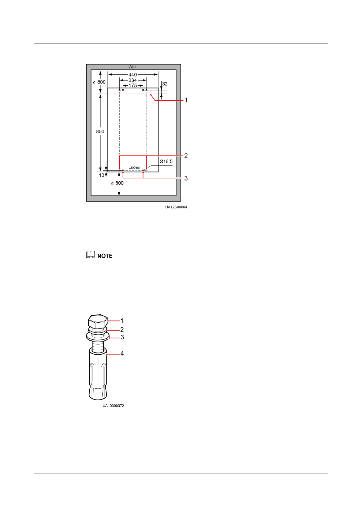
UPS5000-A-30 kVA & 40 kVA & 80 kVA
User Manual
3 Installation
Issue 11 (2018-12-10)
Copyright © Huawei Technologies Co., Ltd.
61
Figure 3-31 Marking-off template (Unit: mm)
(1) Edge of the
cabinet rear
(2) Mounting holes for
antiseismic kits
(3) Mounting holes for L-shaped
brackets
(1) M12 bolt
(2) Spring washer
(3) Flat washer
(4) Expansion sleeve
Pay attention to the front and back edge lines of the cabinet, preventing incorrect location.
Step 2 Use a hammer drill to drill holes for installing the expansion bolts and then install the four
expansion bolts in the holes. Figure 3-32 shows an expansion bolt. Figure 3-33 shows how to
install an expansion bolt.
Figure 3-32 Expansion bolt
Page 71
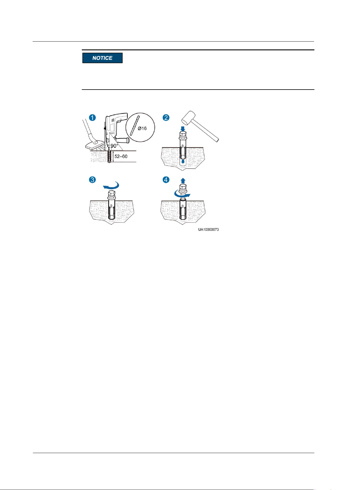
UPS5000-A-30 kVA & 40 kVA & 80 kVA
User Manual
3 Installation
Issue 11 (2018-12-10)
Copyright © Huawei Technologies Co., Ltd.
62
Knock the expansion bolts into the holes until the expansion sleeve completely fits into the
hole. The expansion sleeve must be completely buried under the ground to facilitate
subsequent installation.
Figure 3-33 Installing an expansion bolt (unit: mm)
1. Drill holes in the ground by using a hammer drill. The hole depth is 52 mm to 60 mm.
2. Partially tighten the expansion bolt and vertically insert it into the hole. Knock the
expansion bolt using a rubber mallet until the expansion sleeve is fully inserted into the
hole.
3. Partially tighten the expansion bolt.
4. Remove the bolt, spring washer, and flat washer.
Step 3 Move the UPS to the installation position over its castors.
Step 4 Lower the four leveling feet at the bottom of the UPS using a wrench until all the four castors
at the bottom hang in the air and the leveling feet bear the whole cabinet weight.
Step 5 Secure the two L-shaped brackets to the front and rear of the chassis using eight M6 screws.
Page 72
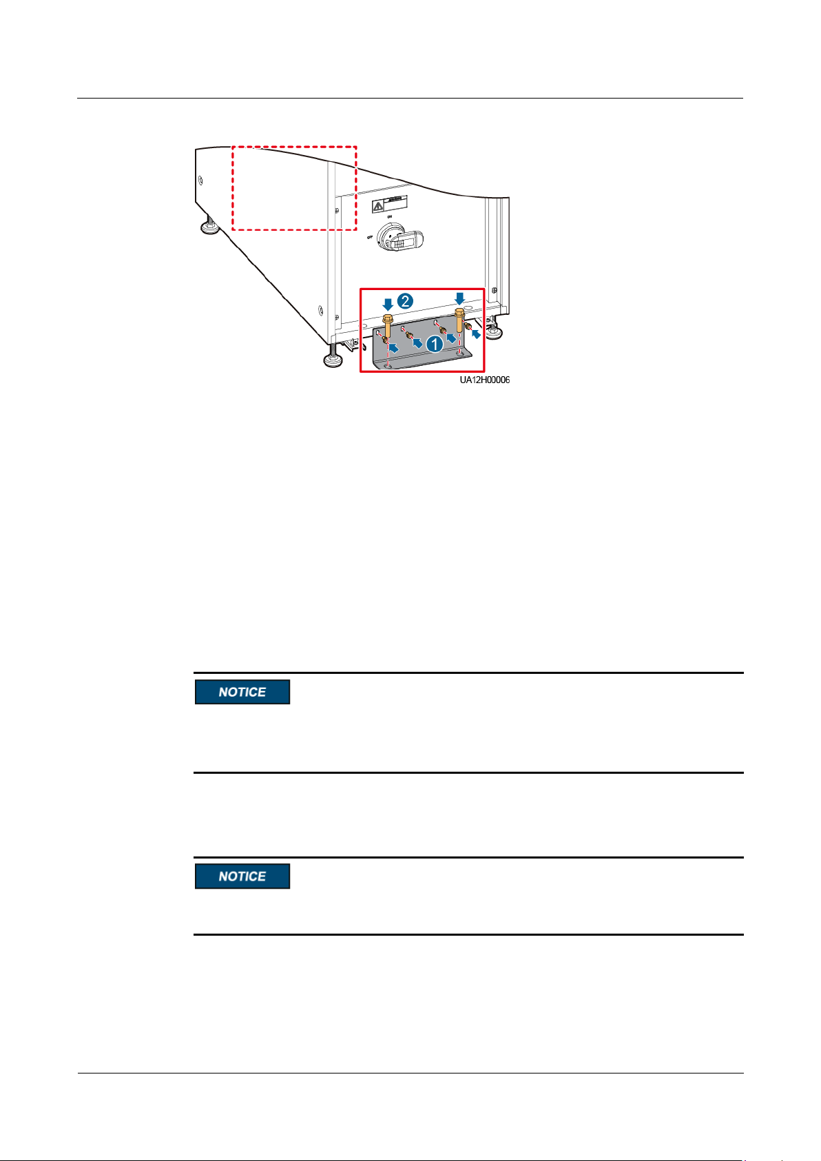
UPS5000-A-30 kVA & 40 kVA & 80 kVA
User Manual
3 Installation
Issue 11 (2018-12-10)
Copyright © Huawei Technologies Co., Ltd.
63
Figure 3-34 Installing the L-shaped brackets
Step 6 Adjust the cabinet position so that the expansion bolt holes are aligned with the four holes at
the bottom of the cabinet.
Step 7 Check the cabinet levelness using a level. If the cabinet is not leveled, adjust the leveling feet.
Step 8 Secure the two L-shaped brackets to the ground using four M12x60 expansion bolts, as shown
in Figure 3-34.
Step 9 Install a lock for the maintenance bypass switch, as shown in Figure 3-30.
----End
Rack-mounting the UPS
The rack must comply with IEC 297. The rack depth is greater than or equal to 1100 mm.
The distance between mounting bars on the same side must be greater than 820 mm.
Reserve sufficient clearance in the lower part of the rack for bottom cable routing.
Step 1 Install guide rails at the bottom of the rack. The guide rail is 2 U high. The methods for
installing guide rails on the left and right sides are the same.
Install the UPS5000-A-80 kVA at the bottom of the rack because it uses bottom cable routing
and weighs more than 160 kg.
1. Level the bottom plane of a guide rail with the bottom line of the U scale 01, and engage
the mounting brackets on both ends of the guide rail into the mounting holes of the
mounting bar, as shown in Figure 3-35.
Page 73
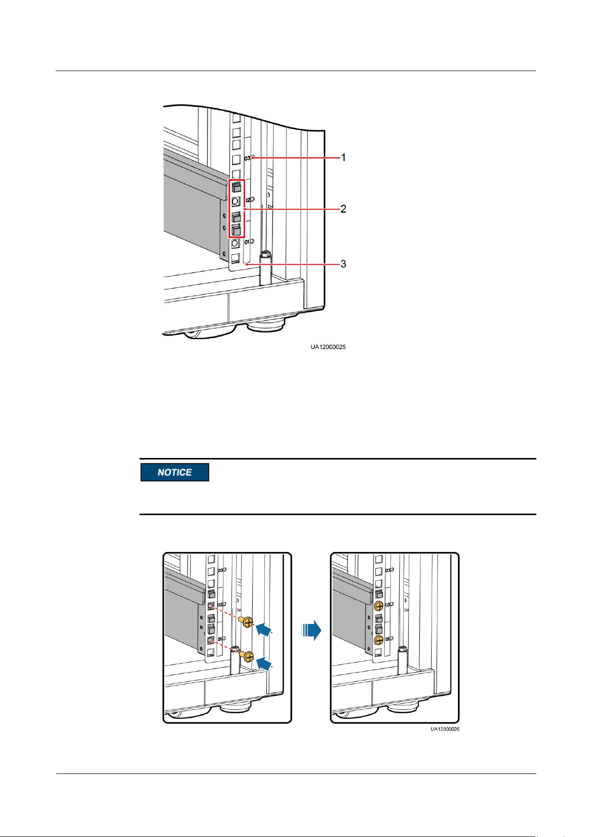
UPS5000-A-30 kVA & 40 kVA & 80 kVA
User Manual
3 Installation
Issue 11 (2018-12-10)
Copyright © Huawei Technologies Co., Ltd.
64
Figure 3-35 Engaging mounting brackets (front view)
(1) Scale
(2) Mounting bracket
(3) Lower edge of a U scale
2. Use panel screws to secure the front and back ends of the guide rail, as shown in Figure
3-36.
Do not fully tighten panel screws, which facilitates subsequent installation of reinforced
beams.
Figure 3-36 Securing a guide rail (front view)
Page 74
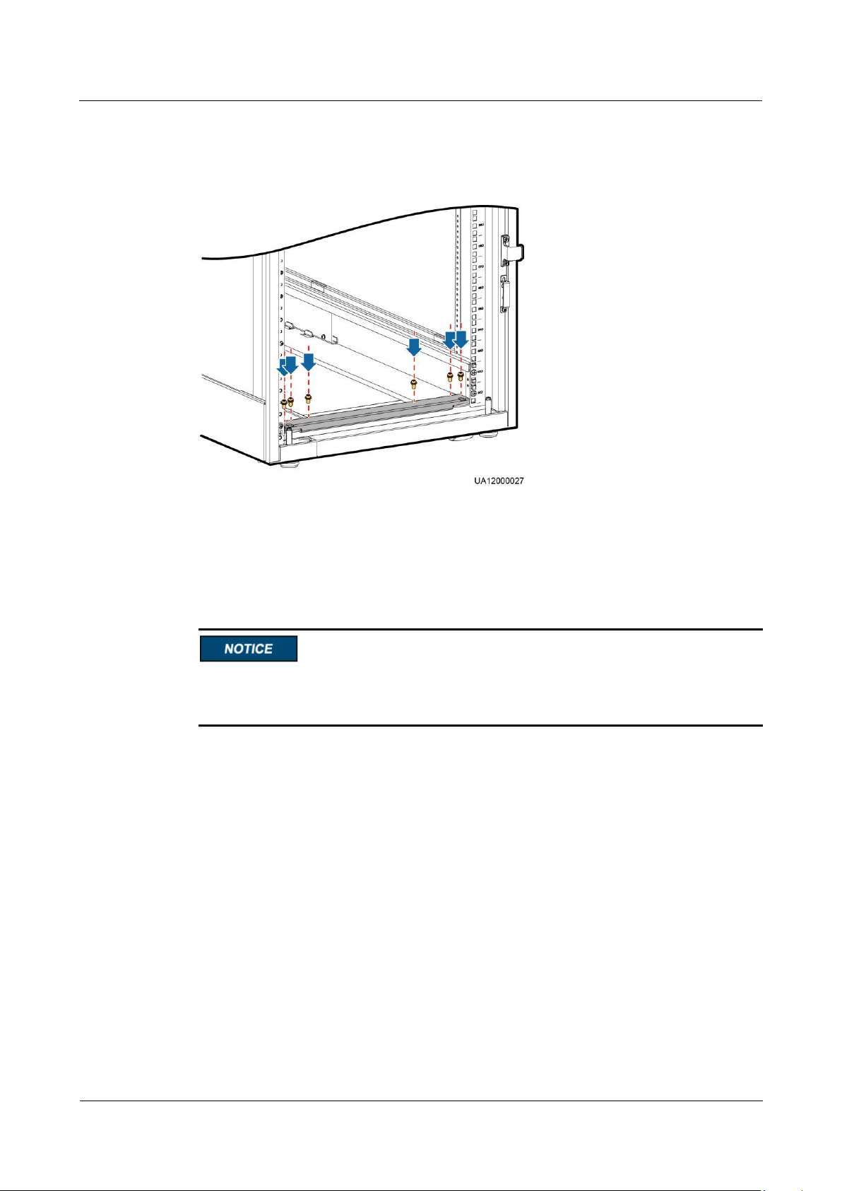
UPS5000-A-30 kVA & 40 kVA & 80 kVA
User Manual
3 Installation
Issue 11 (2018-12-10)
Copyright © Huawei Technologies Co., Ltd.
65
Step 2 Install one reinforced beam on the front and at the rear of the rack, as shown in Figure 3-37.
Then tighten the panel screws.
Figure 3-37 Installing a reinforced beam (front view)
Step 3 Install four floating nuts on the front of each guide rail.
1. Use a scale plate to determine the installation positions of floating nuts. Figure 3-38
shows a scale plate.
Level the Bottom line on the scale plate with the bottom line of the U sale 01 on the rack.
Install floating nuts onto the mounting holes for the mounting bar that corresponds to Hole
location lines.
Page 75
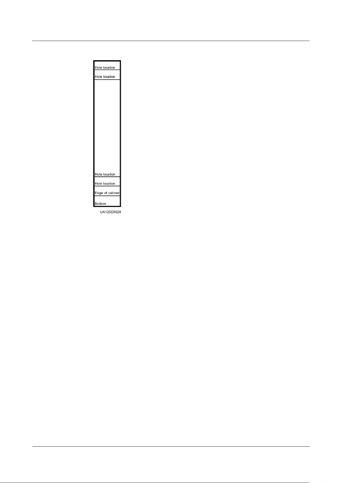
UPS5000-A-30 kVA & 40 kVA & 80 kVA
User Manual
3 Installation
Issue 11 (2018-12-10)
Copyright © Huawei Technologies Co., Ltd.
66
Figure 3-38 Scale plate
2. Install floating nuts, as shown in Figure 3-22. Figure 3-39 shows the installation
positions of floating nuts.
Page 76
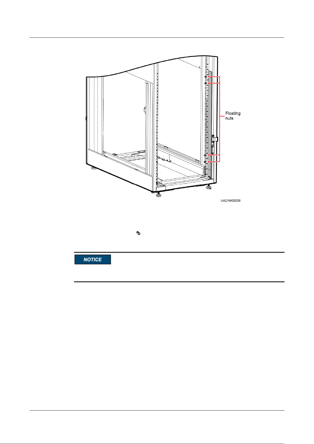
UPS5000-A-30 kVA & 40 kVA & 80 kVA
User Manual
3 Installation
Issue 11 (2018-12-10)
Copyright © Huawei Technologies Co., Ltd.
67
Figure 3-39 Installation positions of floating nuts
Step 4 Remove the UPS front panels, MDU (with its support), power units, and bypass unit, as
shown in Figure 3-40. Before you move the power unit and bypass unit, rotate the ready
switches to unlocked state .
Two persons are required to move a power unit. Keep the power units and bypass unit
horizontal during movement.
Page 77
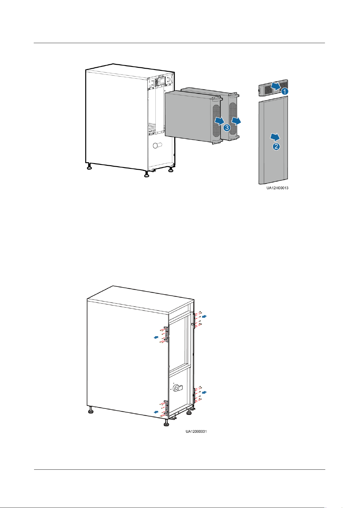
UPS5000-A-30 kVA & 40 kVA & 80 kVA
User Manual
3 Installation
Issue 11 (2018-12-10)
Copyright © Huawei Technologies Co., Ltd.
68
Figure 3-40 Removing the UPS front panels, MDU, power units, and bypass unit
1. Remove UPS front panel 1.
2. Remove UPS front panel 2.
3. Remove the MDU.
4. Remove the power units and bypass unit.
Step 5 Install mounting brackets on the chassis, two on the left and two on the right, as shown in
Figure 3-41.
Figure 3-41 Installing mounting brackets
Page 78
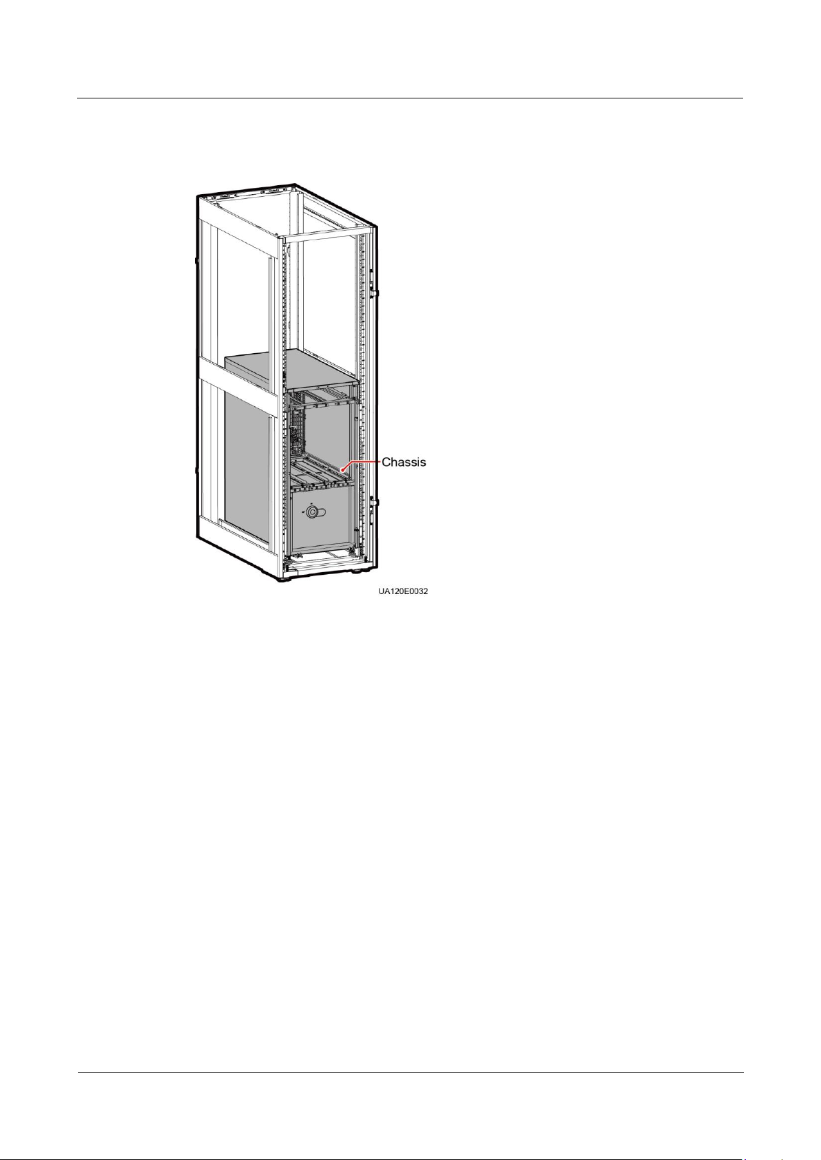
UPS5000-A-30 kVA & 40 kVA & 80 kVA
User Manual
3 Installation
Issue 11 (2018-12-10)
Copyright © Huawei Technologies Co., Ltd.
69
Step 6 Place the chassis into the rack, as shown in Figure 3-42.
Figure 3-42 Placing the chassis into the rack
Step 7 Adjust the four leveling feet using an adjustable wrench until the bottom of the chassis is level
with the Edge of cabinet line on the scale plate, as shown in Figure 3-43.
Page 79
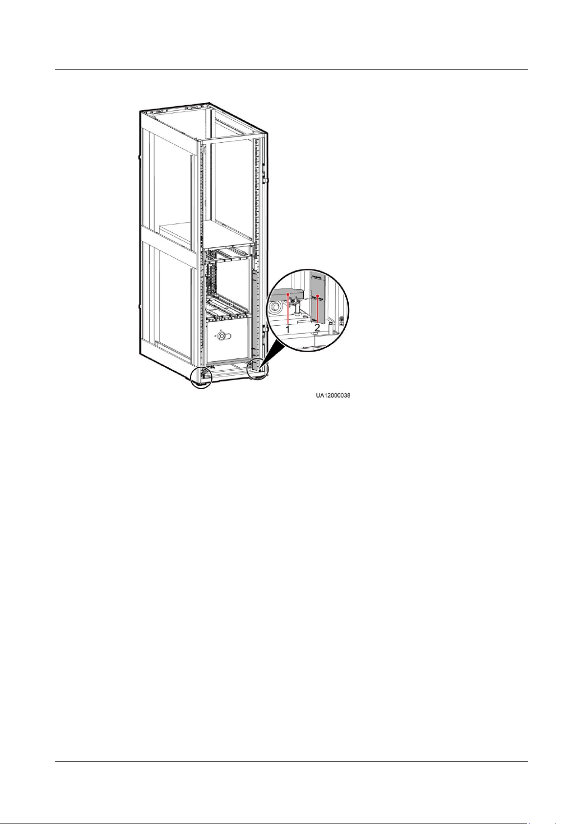
UPS5000-A-30 kVA & 40 kVA & 80 kVA
User Manual
3 Installation
Issue 11 (2018-12-10)
Copyright © Huawei Technologies Co., Ltd.
70
Figure 3-43 Adjusting the leveling feet
(1) Bottom of the chassis
(2) Edge of cabinet line on the scale plate
Step 8 Check the cabinet levelness using a level. If the cabinet is not leveled, adjust the leveling feet.
Step 9 Secure the chassis to the rack, as shown in Figure 3-44.
Page 80
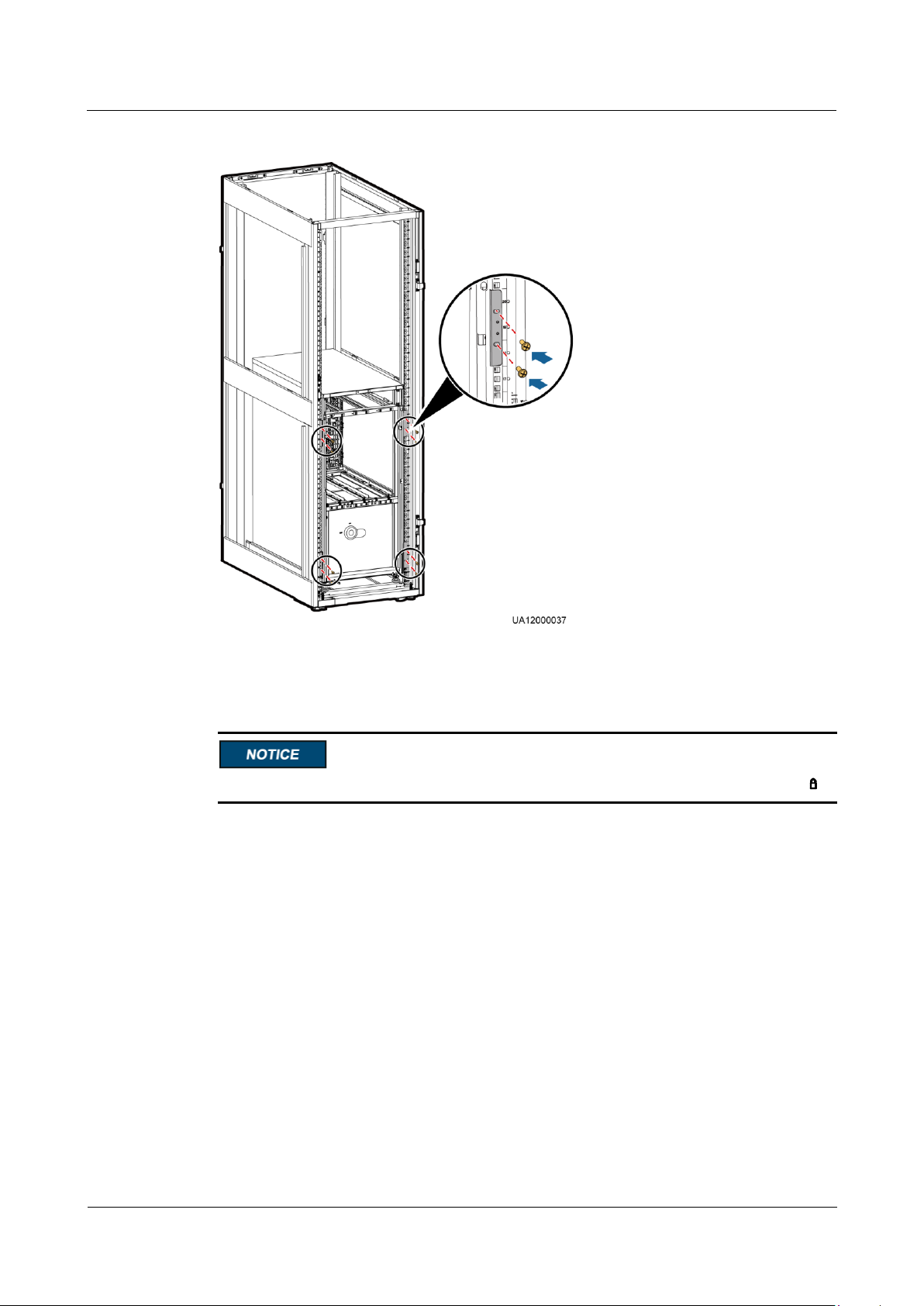
UPS5000-A-30 kVA & 40 kVA & 80 kVA
User Manual
3 Installation
Issue 11 (2018-12-10)
Copyright © Huawei Technologies Co., Ltd.
71
Figure 3-44 Securing the chassis to the rack
Step 10 Reinstall the power units, bypass unit, MDU (with its support), and UPS font panels.
After you insert the power unit and bypass unit, rotate the ready switches to locked state .
Step 11 (Recommended) Install a lock for the maintenance bypass switch, as shown in Figure 3-30.
----End
3.2.3 (Optional) Installing Antiseismic Kits
Step 1 Determine the positions for installing antiseismic kits based on the marking-off template.
Step 2 Drill holes for installing expansion bolts, and install expansion bolts.
Step 3 Move the UPS to the installation position over its castors.
Step 4 Remove the lower front panel of the UPS and PDU cover.
Step 5 Secure two antiseismic kits to the front and rear of the chassis using eight M6 screws and four
M12 screws.
Page 81
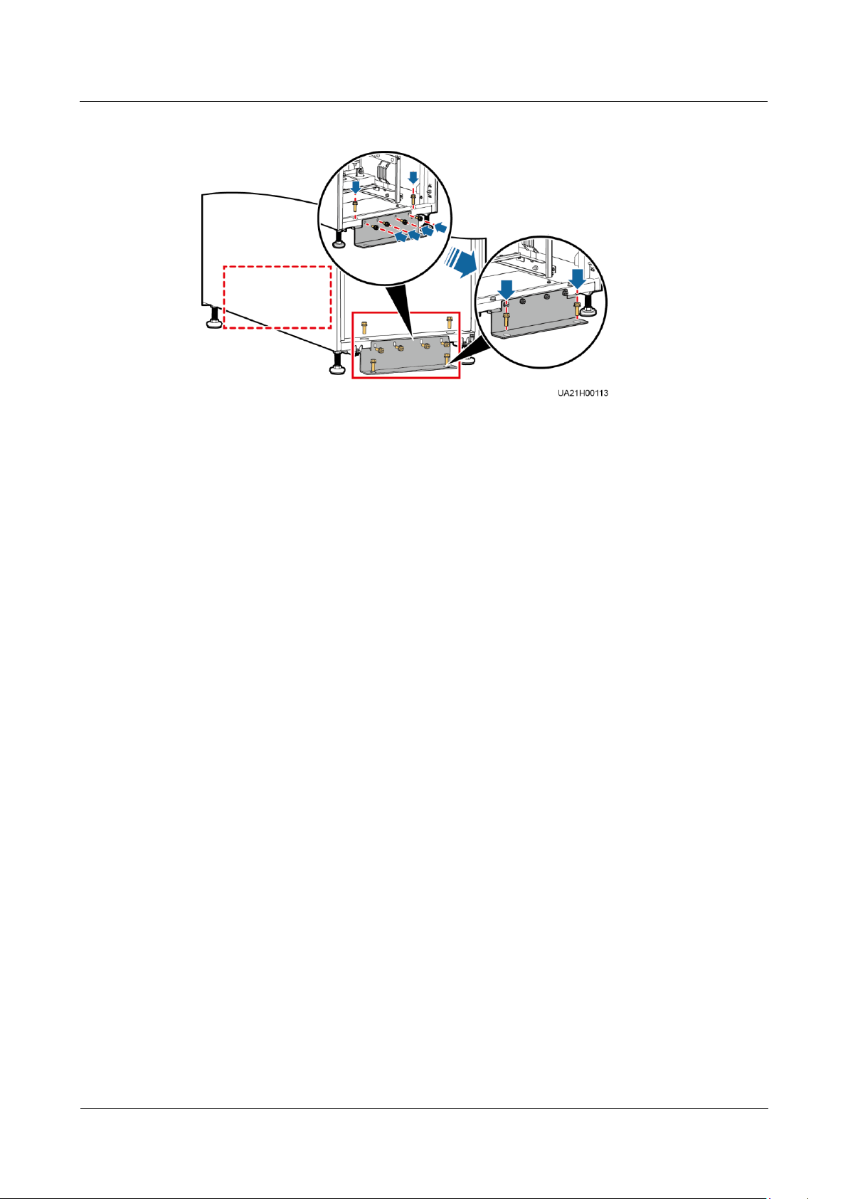
UPS5000-A-30 kVA & 40 kVA & 80 kVA
User Manual
3 Installation
Issue 11 (2018-12-10)
Copyright © Huawei Technologies Co., Ltd.
72
Figure 3-45 Securing antiseismic kits to the cabinet
Step 6 Adjust the cabinet position so that the expansion bolt holes are aligned with the four holes at
the bottom of the cabinet.
Step 7 Check the cabinet levelness using a level. If the cabinet is not leveled, adjust the leveling feet.
Step 8 Secure the two antiseismic components to the floor using four M12x60 expansion bolts, as
shown in Figure 3-45.
Step 9 Reinstall the lower front panel of the UPS and PDU cover.
----End
3.2.4 (Optional) Installing a Battery Monitoring Unit
Connect the BMU by using a 04080298 transfer cable, which is delivered with the BMU.
When no ambient temperature and humidity sensor is installed, connect the BMU to the
COM1 port on the UPS. Figure 3-46 shows the position of the BMU on the UPS.
When an ambient temperature and humidity sensor is installed, connect the BMU to the
RS485_OUT port on the sensor. Figure 3-47 shows the position of the BMU on the UPS.
Page 82
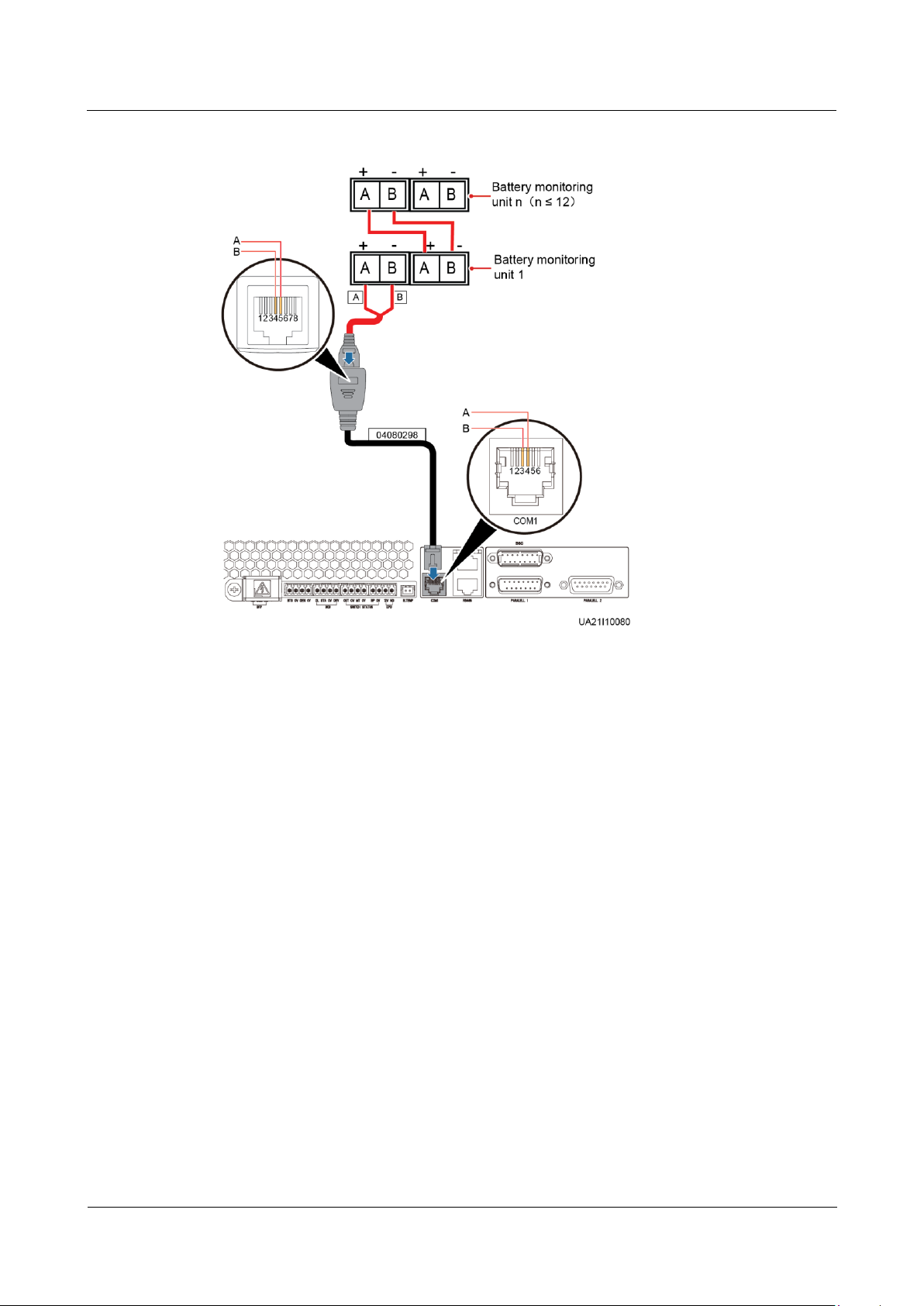
UPS5000-A-30 kVA & 40 kVA & 80 kVA
User Manual
3 Installation
Issue 11 (2018-12-10)
Copyright © Huawei Technologies Co., Ltd.
73
Figure 3-46 Connecting the UPS and BMU (without ambient temperature and humidity sensor)
Page 83
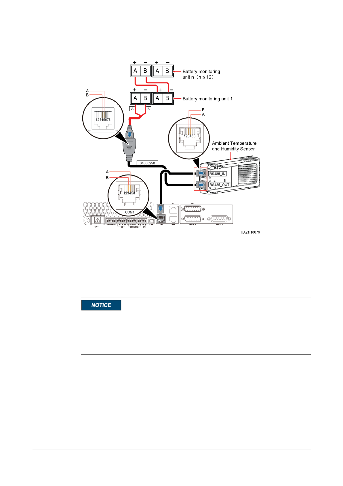
UPS5000-A-30 kVA & 40 kVA & 80 kVA
User Manual
3 Installation
Issue 11 (2018-12-10)
Copyright © Huawei Technologies Co., Ltd.
74
Figure 3-47 Connecting the UPS and BMU (with ambient temperature and humidity sensor)
3.2.5 Installing Batteries
Context
Before installing batteries, read through the battery safety precautions, obtain the delivered
battery installation guide, and install batteries as instructed.
Place the batteries in a correct way to prevent vibrations and shocks.
Install the batteries from the lower layer to the upper layer to prevent falling over due to
imbalance.
Procedure
Step 1 Install the battery rack and batteries.
For details, see the battery installation guide delivered with batteries.
Step 2 (Optional) Install a BCB box.
Page 84

UPS5000-A-30 kVA & 40 kVA & 80 kVA
User Manual
3 Installation
Issue 11 (2018-12-10)
Copyright © Huawei Technologies Co., Ltd.
75
After you install the BCB box, adjust the end of discharge (EOD) threshold based on backup
time, which prevents overcurrent disconnection. The default values are as follows:
Backup time < 1 h: Set the EOD threshold to 1.67 V/cell.
3 h > Backup time ≥ 1 h: Set the EOD threshold to 1.75 V/cell.
Backup time ≥ 3 h: Set the EOD threshold to 1.80 V/cell.
Step 3 (Optional) Install a BBB box.
----End
3.2.6 UPS Cable Connection Reference
Context
Keep away from cabinets when preparing cables to prevent cable scraps from entering the
cabinets. Cable scraps may cause ignition during power-on and result in personal injury
and device damage.
After installing cables, clean the cabinet top, bottom, copper bar wiring positions, and
other positions. Ensure that there is no dust or scraps inside and around cabinets.
Prepare terminals onsite. The length of the copper wire should be the same as that of the
part of the terminal that covers the conductor.
Procedure
Step 1 Route a cable into the cabinet and bind it to a nearby beam.
Step 2 Pull the cable to the copper bar to which the cable is to be connected, determine the cable
Step 3 Pull the marked cable out of the cabinet, cut the cable from the marked position, strip the
length, and mark the cable at the position where the cable is to be cut.
cable, and crimp a terminal.
Page 85
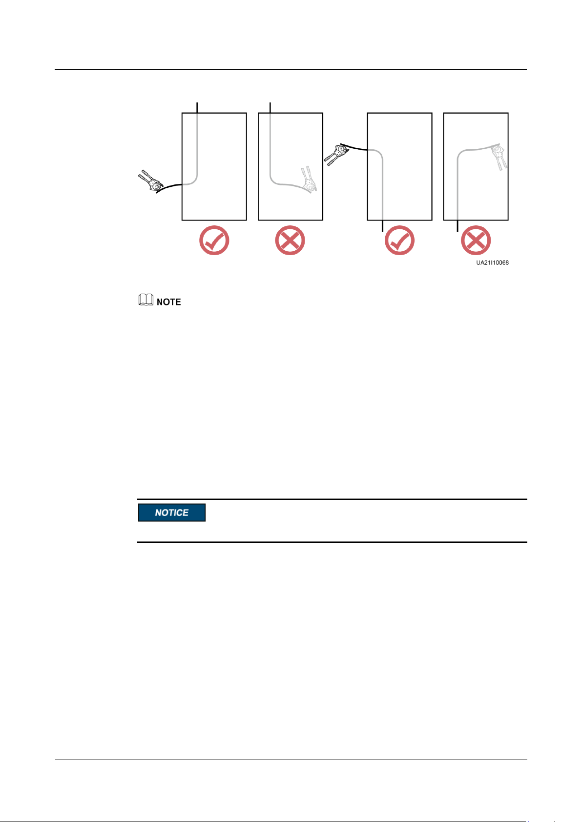
UPS5000-A-30 kVA & 40 kVA & 80 kVA
User Manual
3 Installation
Issue 11 (2018-12-10)
Copyright © Huawei Technologies Co., Ltd.
76
Figure 3-48 Preparing a cable terminal outside the cabinet
Choose an appropriate cabling route based on the actual situation. The figure is for reference only.
Step 4 Connect the cable with a crimped terminal to the corresponding copper bar.
Step 5 Clean foreign matter inside the cabinet.
----End
3.2.7 Routing Cables
3.2.7.1 Cable Routes
Context
Cable routings for only the UPS5000-A-80 kVA are elaborated in this section.
Procedure
Step 1 Remove the power distribution unit (PDU) cover, as shown in Figure 3-49.
Page 86
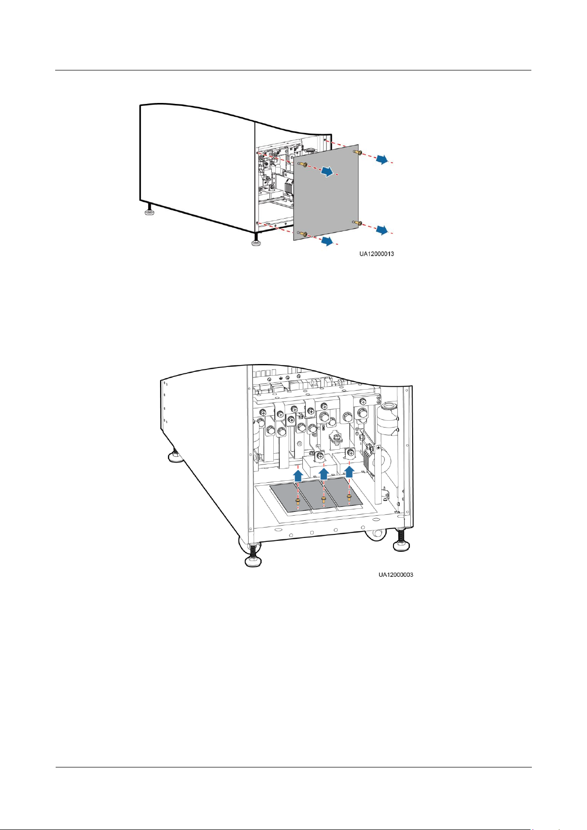
UPS5000-A-30 kVA & 40 kVA & 80 kVA
User Manual
3 Installation
Issue 11 (2018-12-10)
Copyright © Huawei Technologies Co., Ltd.
77
Figure 3-49 Removing the PDU cover
Step 2 Route power cables.
1. Remove 1–3 covers from the bottom of the cabinet based on the number and positions of
cables, as shown in Figure 3-50.
Figure 3-50 Removing small covers from the bottom of the cabinet
2. Figure 3-51 shows the power cables routed from the bottom of the cabinet.
Page 87
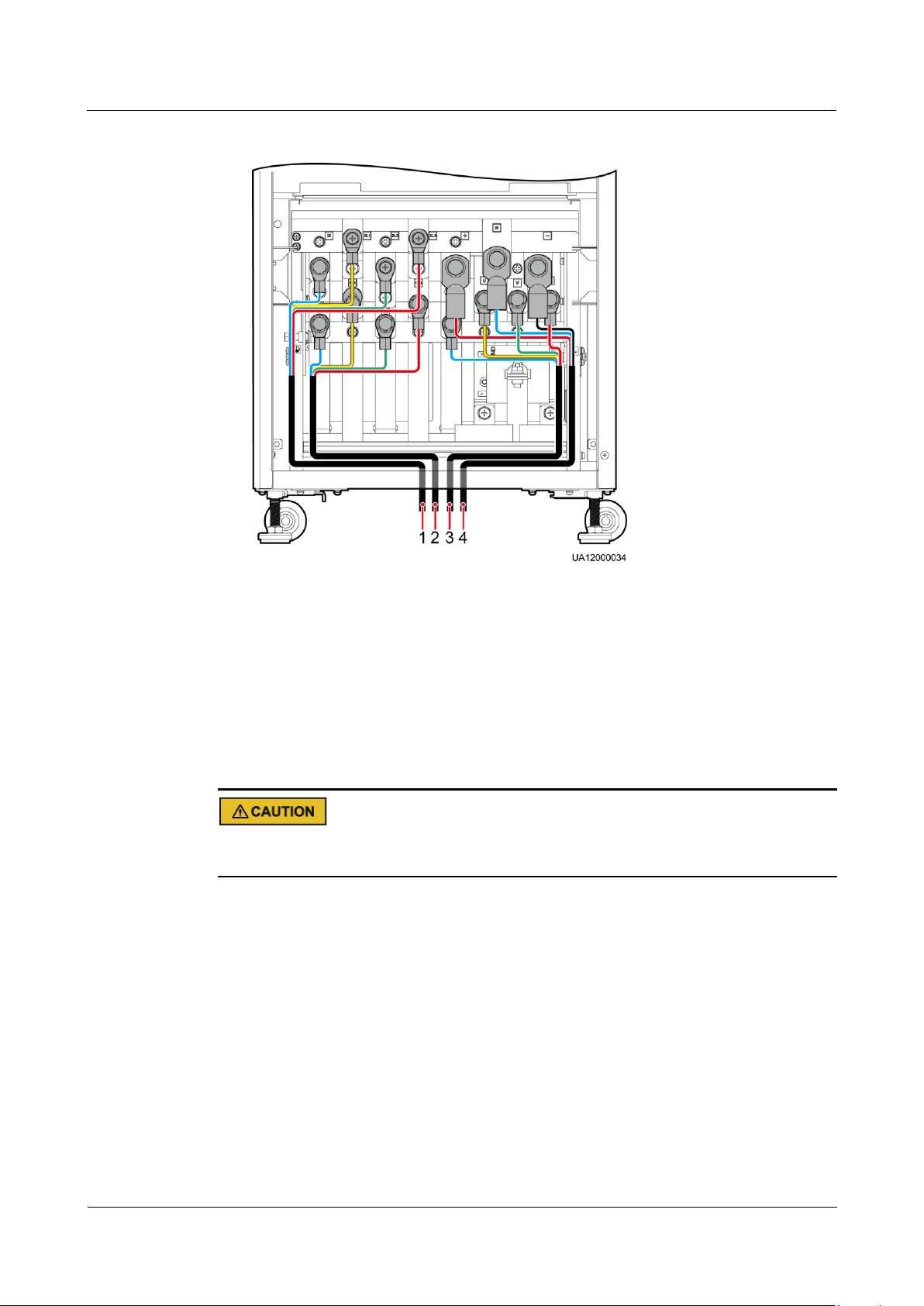
UPS5000-A-30 kVA & 40 kVA & 80 kVA
User Manual
3 Installation
Issue 11 (2018-12-10)
Copyright © Huawei Technologies Co., Ltd.
78
Figure 3-51 Routing power cables from the bottom of the cabinet
(1) Bypass input
power cable
(2) Mains input
power cable
(3) Output power
cable
(4) Battery input
power cable
----End
3.2.7.2 Connecting Ground Cables
If you do not ground the UPS as required, electromagnetic interference, electric shocks, or fire
disasters may occur.
Page 88
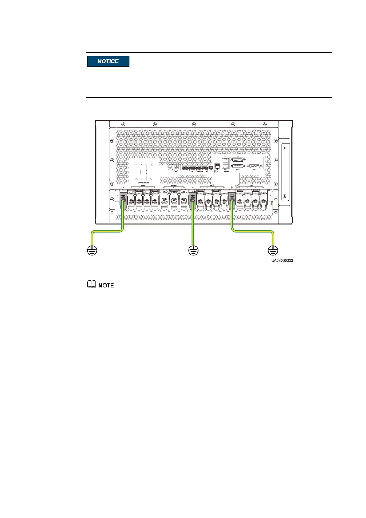
UPS5000-A-30 kVA & 40 kVA & 80 kVA
User Manual
3 Installation
Issue 11 (2018-12-10)
Copyright © Huawei Technologies Co., Ltd.
79
Before cable connections, ensure that all UPS input switches are OFF. Paste warning
labels to prevent operation on the switches.
The basic rule for routing cables is: from inside out and from bottom up.
Figure 3-52 Grounding the UPS5000-A-30 kVA/40 kVA
The three ground cables shown in Figure 3-52 are all connected by default.
Page 89
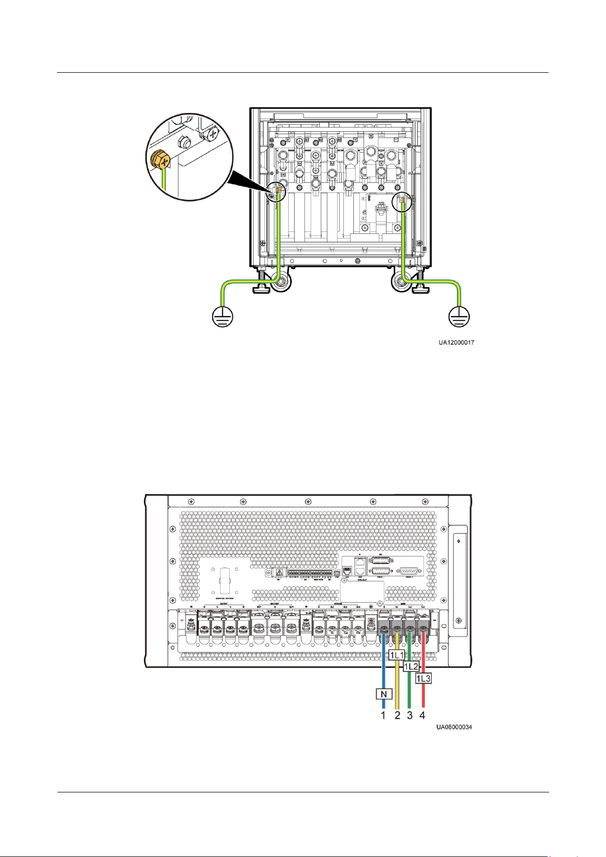
UPS5000-A-30 kVA & 40 kVA & 80 kVA
User Manual
3 Installation
Issue 11 (2018-12-10)
Copyright © Huawei Technologies Co., Ltd.
80
Figure 3-53 Grounding the UPS5000-A-80 kVA
(1) Input N
(2) Input 1L1
(3) Input 1L2
(4) Input 1L3
3.2.7.3 Connecting AC Input Power Cables
Single Mains
Step 1 If the mains input and bypass input share a power source, connect AC input power cables to
mains input terminals N, and 1L1, 1L2, 1L3 on the UPS.
Figure 3-54 Connecting AC input power cables to the UPS5000-A-30 kVA/40 kVA
Page 90
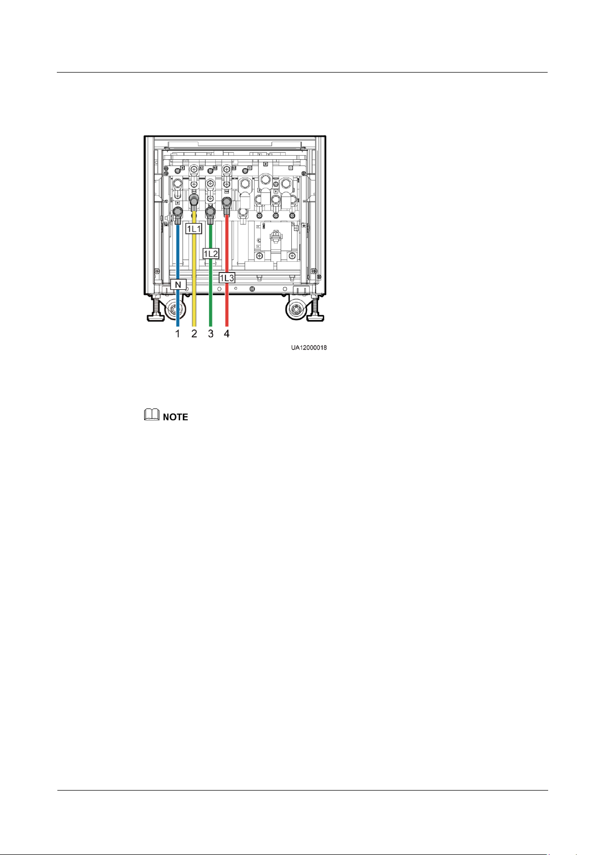
UPS5000-A-30 kVA & 40 kVA & 80 kVA
User Manual
3 Installation
Issue 11 (2018-12-10)
Copyright © Huawei Technologies Co., Ltd.
81
(1) Input N
(2) Input 1L1
(3) Input 1L2
(4) Input 1L3
Figure 3-55 Connecting AC input power cables to the UPS5000-A-80 kVA
Dual Mains
Step 1 Remove the copper bars between mains input terminals and bypass input terminals, as shown
Mains and bypass input of the delivered UPSs by default share one power source. The neutral
terminals of the mains and the bypass are interconnected internally. No copper bars are required.
The neutral terminals of the UPS5000-A-80 kVA are near the interior of the cabinet. It is
recommended to connect the neutral cable before other power cables.
----End
in Figure 3-56 and Figure 3-57.
Page 91
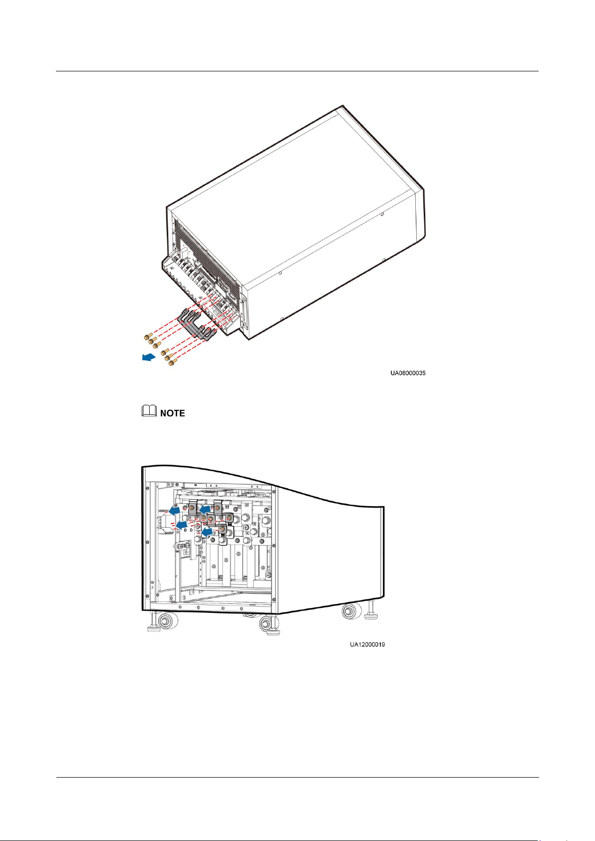
UPS5000-A-30 kVA & 40 kVA & 80 kVA
User Manual
3 Installation
Issue 11 (2018-12-10)
Copyright © Huawei Technologies Co., Ltd.
82
Figure 3-56 Removing copper bars from the UPS5000-A-30 kVA/40 kVA
Install the copper bars from within outwards based on the ascending order of their numbers.
Figure 3-57 Removing copper bars from the UPS5000-A-80 kVA
Step 2 Connect mains input cables to mains input terminals N, and 1L1, 1L2, 1L3 on the UPS
cabinet. Connect bypass input cables to bypass input terminals N, and 2L1, 2L2, 2L3 on the
UPS cabinet, as shown in Figure 3-58 and Figure 3-59.
Page 92
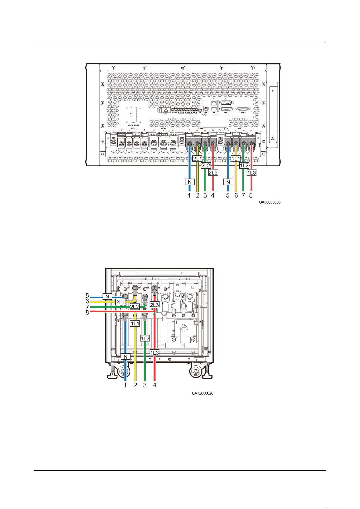
UPS5000-A-30 kVA & 40 kVA & 80 kVA
User Manual
3 Installation
Issue 11 (2018-12-10)
Copyright © Huawei Technologies Co., Ltd.
83
Figure 3-58 Connecting AC input power cables to the UPS5000-A-30 kVA/40 kVA
(1) Bypass input N
(2) Bypass input 2L1
(3) Bypass input 2L2
(4) Bypass input 2L3
(5) Mains input N
(6) Mains input 1L1
(7) Mains input 1L2
(8) Mains input 1L3
(1) Mains input N
(2) Mains input 1L1
(3) Mains input 1L2
(4) Mains input 1L3
(5) Bypass input N
(6) Bypass input 2L1
(7) Bypass input 2L2
(8) Bypass input 2L3
Figure 3-59 Connecting AC input power cables to the UPS5000-A-80 kVA
Page 93
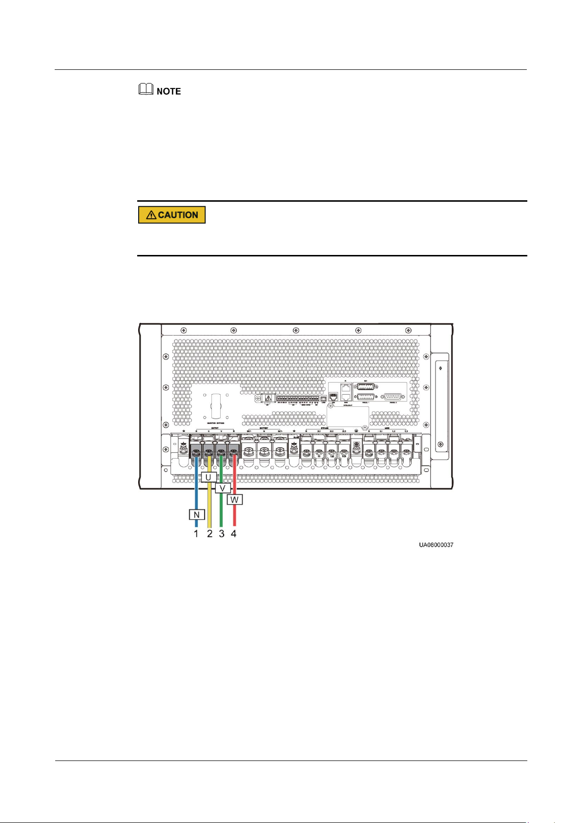
UPS5000-A-30 kVA & 40 kVA & 80 kVA
User Manual
3 Installation
Issue 11 (2018-12-10)
Copyright © Huawei Technologies Co., Ltd.
84
(1) Output N
(2) Output U
(3) Output V
(4) Output W
The neutral terminals of the UPS5000-A-80 kVA are near the interior of the cabinet. It is recommended
to connect the neutral cable before other power cables.
----End
3.2.7.4 Connecting AC Output Power Cables
After you connect output power cables, if loads are not ready to be powered, insulate the end
of the system output power cable.
Connect AC output power cables to output terminals N, U, V, and W on the UPS cabinet, as
shown in Figure 3-60 and Figure 3-61.
Figure 3-60 Connecting AC output power cables to the UPS5000-A-30 kVA/40 kVA
Page 94
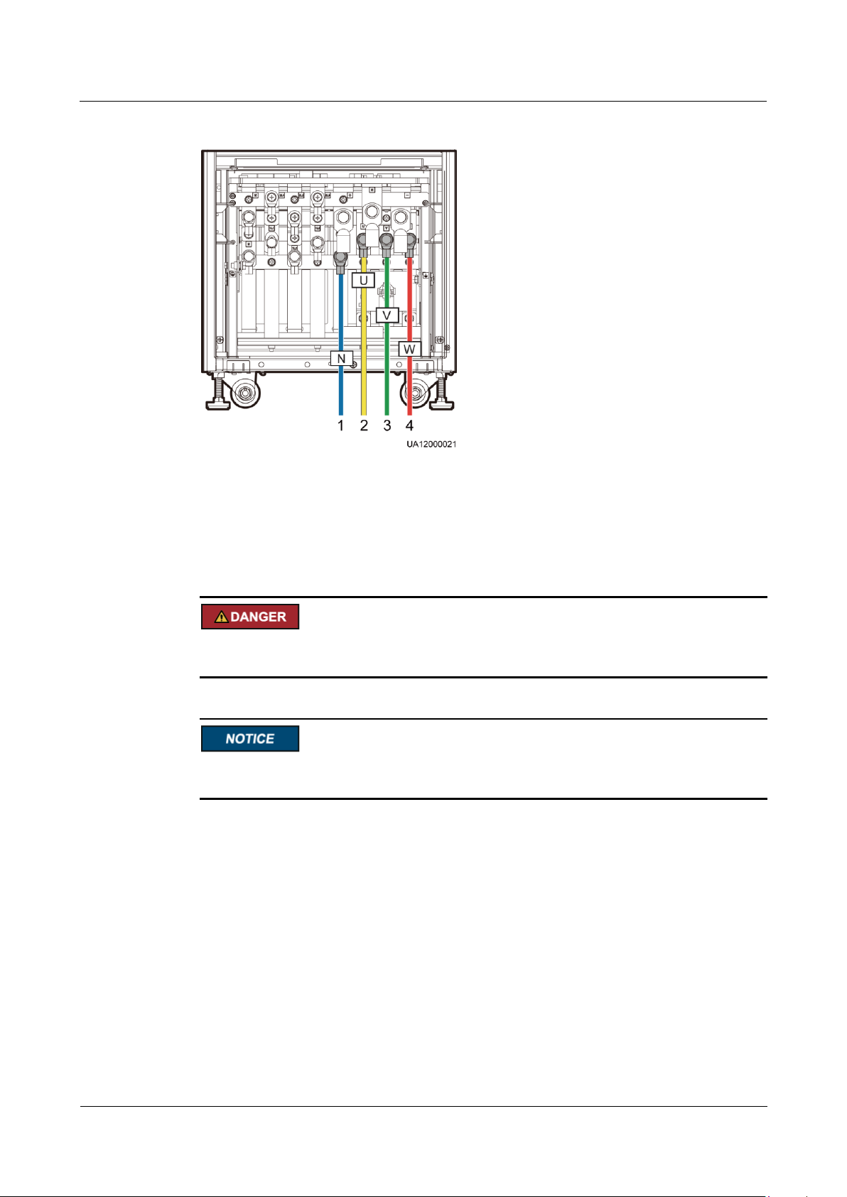
UPS5000-A-30 kVA & 40 kVA & 80 kVA
User Manual
3 Installation
Issue 11 (2018-12-10)
Copyright © Huawei Technologies Co., Ltd.
85
Figure 3-61 Connecting AC output power cables to the UPS5000-A-80 kVA
(1) Output N
(2) Output U
(3) Output V
(4) Output W
3.2.7.5 Connecting Battery Cables
The battery voltage may result in serious injury. Observe safety precautions when connecting
cables.
Ensure that cables are correctly connected between battery strings and the battery switch, and
between the battery switch and the UPS. Avoid inverse connections.
Connect battery cables to battery terminals +, N, and – on the UPS cabinet, as shown in
Figure 3-62 and Figure 3-63.
Page 95
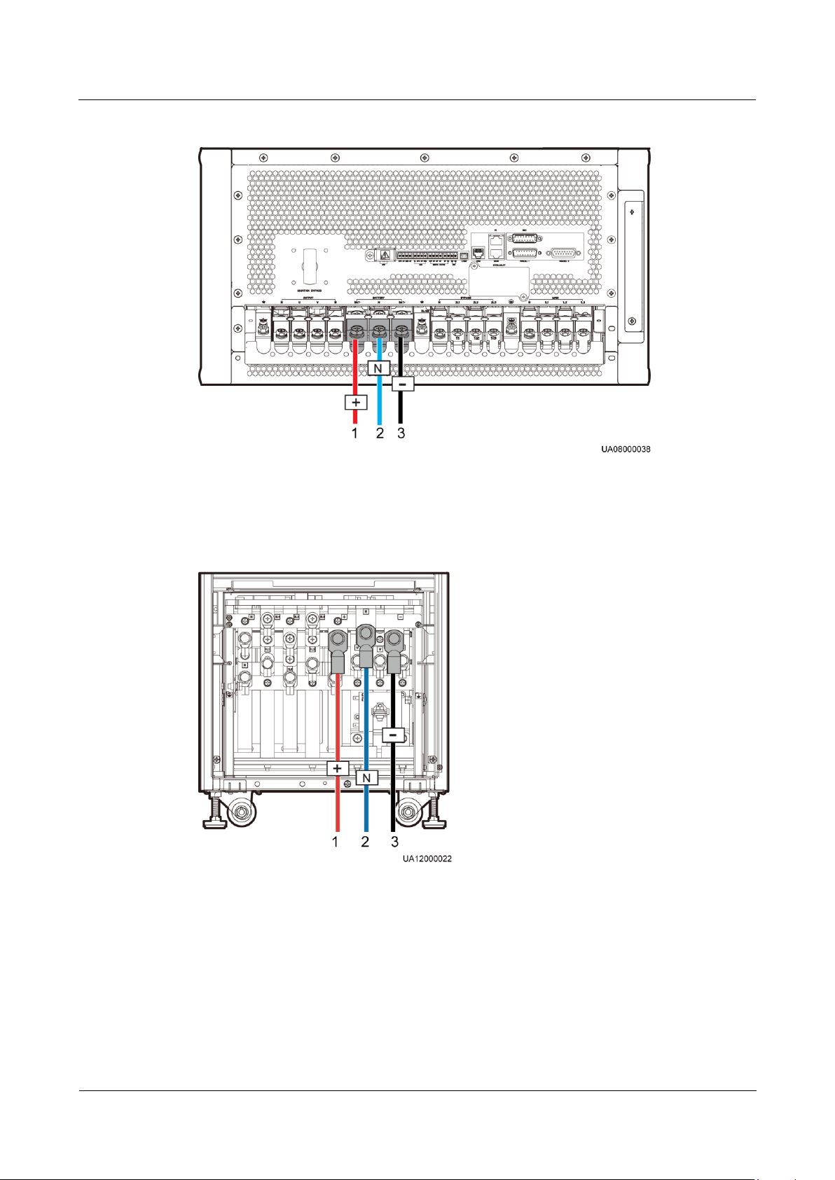
UPS5000-A-30 kVA & 40 kVA & 80 kVA
User Manual
3 Installation
Issue 11 (2018-12-10)
Copyright © Huawei Technologies Co., Ltd.
86
Figure 3-62 Connecting battery cables to the UPS5000-A-30 kVA/40 kVA
(1) Battery input +
(2) Battery input N
(3) Battery input –
(1) Battery input +
(2) Battery input N
(3) Battery input –
Figure 3-63 Connecting battery cables to the UPS5000-A-80 kVA
A neutral wire is routed from the middle of the positive and negative battery strings.
Figure 3-64 shows a neutral wire routed from the middle of the two battery strings consisting
of 40 batteries, half positive and half negative.
Page 96
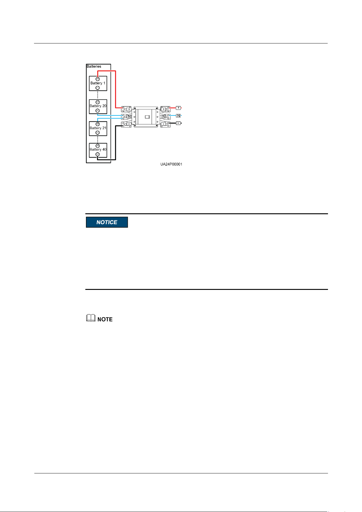
UPS5000-A-30 kVA & 40 kVA & 80 kVA
User Manual
3 Installation
Issue 11 (2018-12-10)
Copyright © Huawei Technologies Co., Ltd.
87
Figure 3-64 Neutral wire
3.2.8 Remote EPO
Huawei does not provide the EPO switch or cable. Prepare them by yourself. The
recommended cable is 22 AWG.
Equip the EPO switch with a protective cover to prevent misoperations, and cover the
cable with protective tubing.
Triggering EPO will shut down the rectifier, inverter, charger, and static bypass, but does
not disconnect the UPS mains input. To power off the UPS completely, turn off the
front-end input switch when you trigger EPO.
Connect the EPO switch to specified dry contacts on the UPS. Figure 3-65 uses the
UPS5000-A-30 kVA/40 kVA UPS as an example.
By default, the EPO switch is NO. When you turn on the EPO switch, EPO is triggered.
Page 97
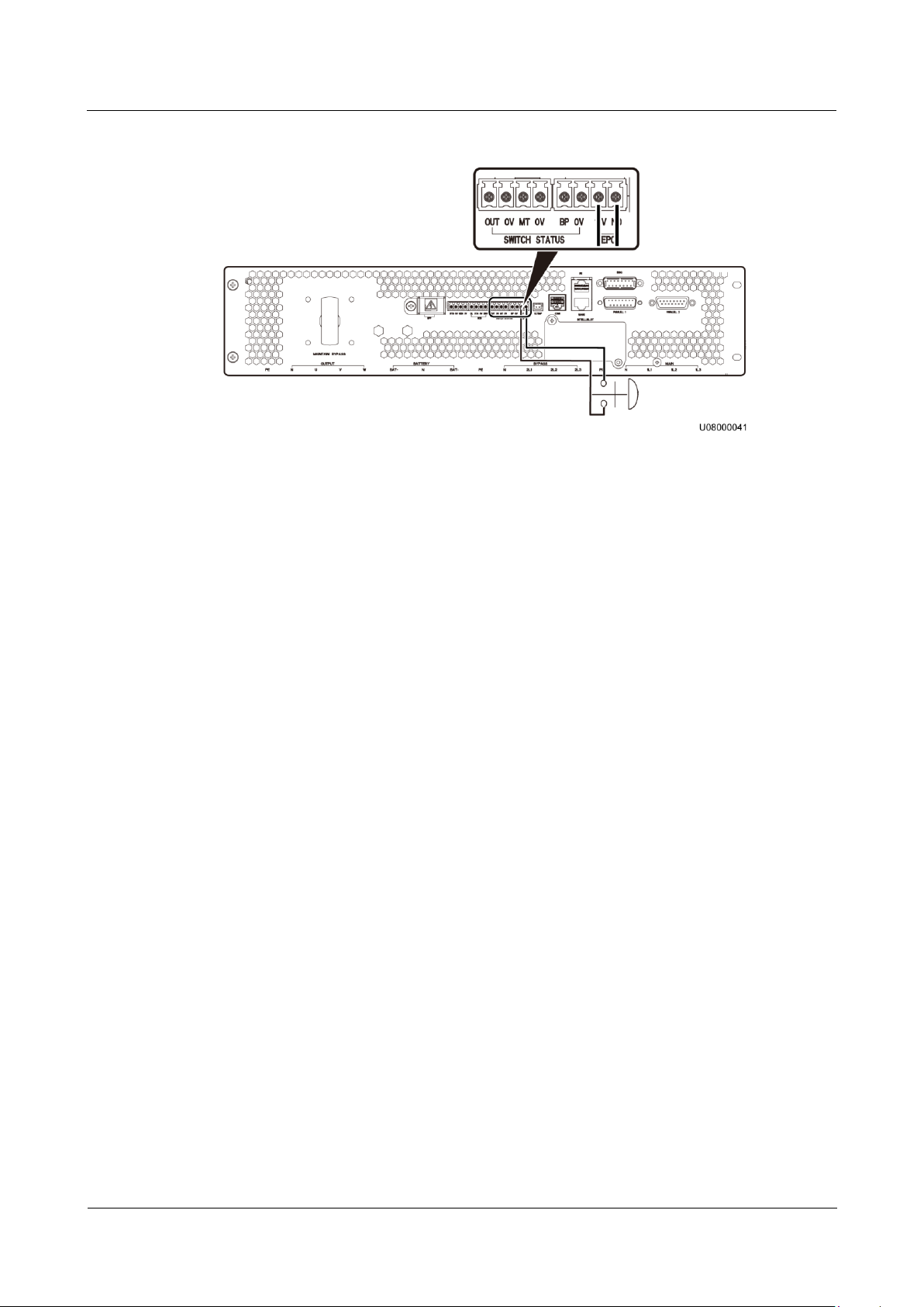
UPS5000-A-30 kVA & 40 kVA & 80 kVA
User Manual
3 Installation
Issue 11 (2018-12-10)
Copyright © Huawei Technologies Co., Ltd.
88
Figure 3-65 EPO NO status
3.2.9 Connecting Communications Cables
Procedure
Step 1 Connect the external network management device to the RS485 port.
Step 2 Connect the network port on a PC to the FE port.
----End
3.3 Installing a Parallel System
3.3.1 Connecting Power Cables
Procedure
Step 1 Ground each UPS.
Step 2 Connect input power cables to each UPS.
Step 3 Connect output power cables to each UPS.
Step 4 Connect battery cables to each UPS.
Step 5 Select a parallel connection method to connect cables to the parallel system based on site
configurations.
Figure 3-66, Figure 3-67 and Figure 3-68 show the typical conceptual diagram and cable
connections for a 1+1 parallel system.
Page 98
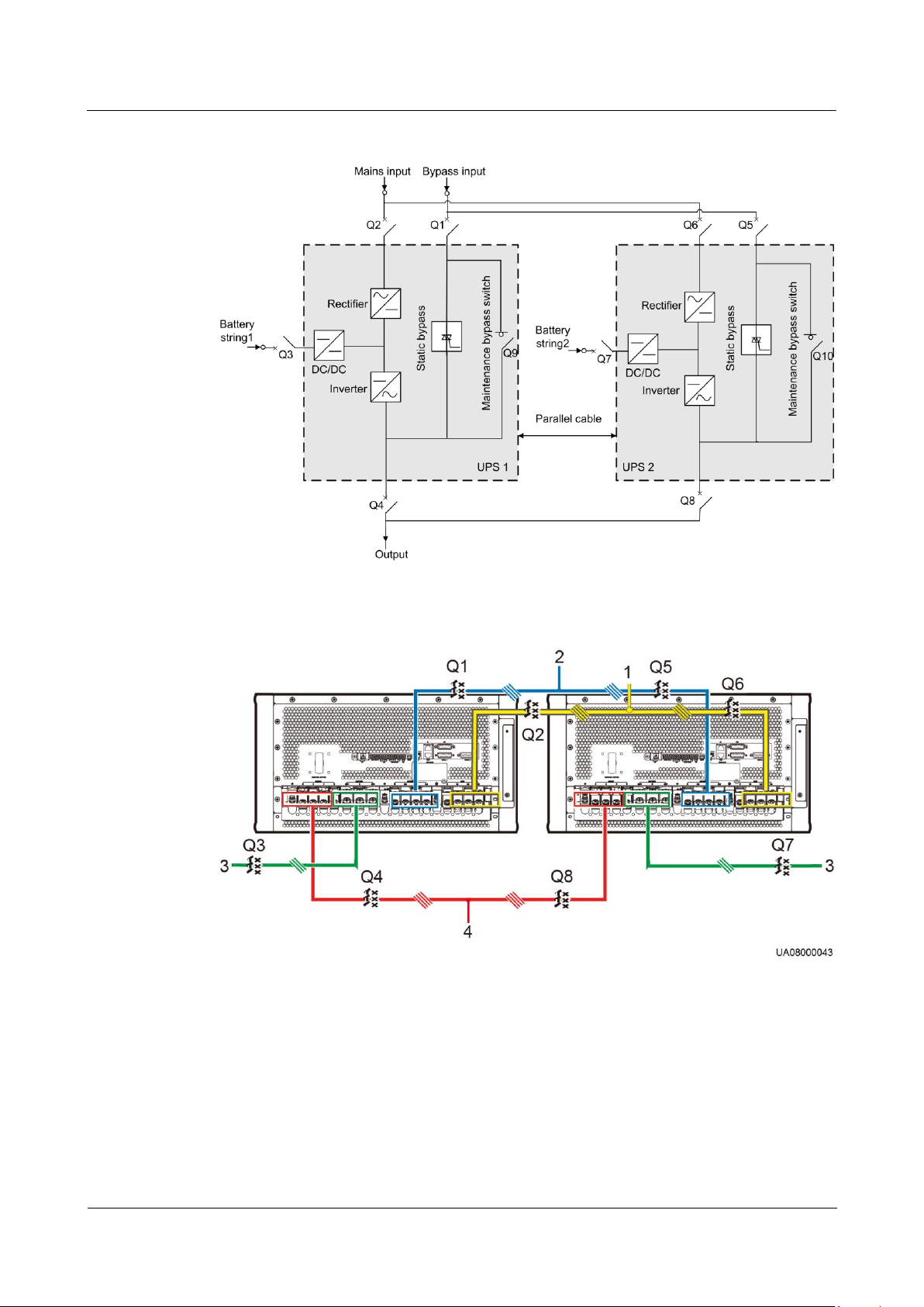
UPS5000-A-30 kVA & 40 kVA & 80 kVA
User Manual
3 Installation
Issue 11 (2018-12-10)
Copyright © Huawei Technologies Co., Ltd.
89
Figure 3-66 Conceptual diagram of a 1+1 parallel system
(1) Mains input power
cable
(2) Bypass input power
cable
(3) Battery
cable
(4) Output power
cable
Figure 3-67 Cable connections for a UPS5000-A-30 kVA/40 kVA 1+1 parallel system
Page 99
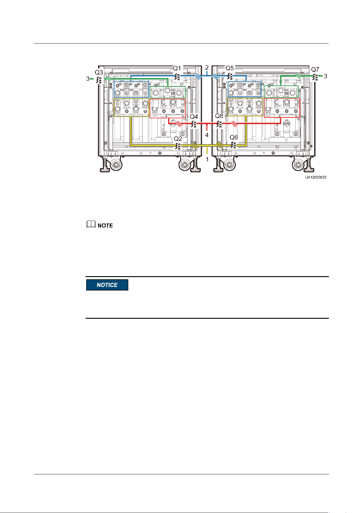
UPS5000-A-30 kVA & 40 kVA & 80 kVA
User Manual
3 Installation
Issue 11 (2018-12-10)
Copyright © Huawei Technologies Co., Ltd.
90
Figure 3-68 Cable connections for a UPS5000-A-80 kVA 1+1 parallel system
(1) Mains input power
cable
(2) Bypass input power
cable
(3) Battery
cable
(4) Output power
cable
To clearly and simply show cable connections, this document uses "the number of oblique lines" to
indicate the number of power cables of the same type.
Do not configure circuit breakers for the mains and bypass input N wires and output N wire.
Connect power cables according to port silk screen.
The specifications of power cables on each UPS should be the same to achieve current
equalization in bypass mode. The power cables include bypass input power cables and UPS
output power cables.
Figure 3-69, Figure 3-70, and Figure 3-71 show the conceptual diagram and cable connections
for a bus system consisting of two UPS systems respectively.
Page 100
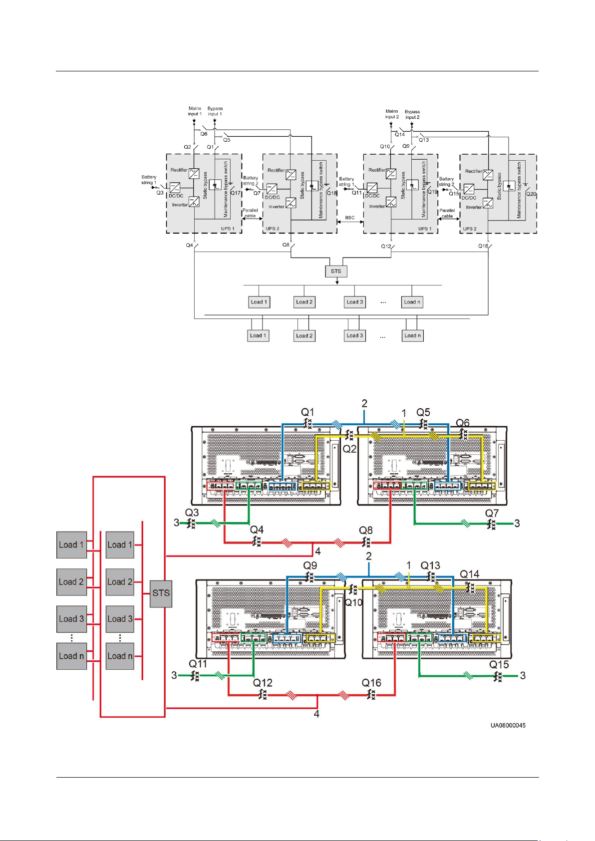
UPS5000-A-30 kVA & 40 kVA & 80 kVA
User Manual
3 Installation
Issue 11 (2018-12-10)
Copyright © Huawei Technologies Co., Ltd.
91
Figure 3-69 Conceptual diagram of a dual-bus system
(1) Mains input power
(2) Bypass input power
(3) Battery
(4) Output power
Figure 3-70 Cable connections for a UPS5000-A-30 kVA/40 kVA dual-bus system
 Loading...