

Huawei U9500 Maintenance Manual
U9500 Maintenance Guide
Issue
1.2
Date
2012-06-30
HUAWEI TECHNOLOGIES CO., LTD.

Issue 1.2 (2012-6-30)
Huawei Proprietary and Confidential
Copyright © Huawei Technologies Co., Ltd.
ii
Copyright © Huawei Technologies Co., Ltd. 2012. All rights reserved.
No part of this document may be reproduced or transmitted in any form or by any means without prior
written consent of Huawei Technologies Co., Ltd.
Trademarks and Permissions
and other Huawei trademarks are trademarks of Huawei Technologies Co., Ltd.
All other trademarks and trade names mentioned in this document are the property of their respective
holders.
Notice
The purchased products, services and features are stipulated by the contract made between Huawei and
the customer. All or part of the products, services and features described in this document may not be
within the purchase scope or the usage scope. Unless otherwise specified in the contract, all statements,
information, and recommendations in this document are provided "AS IS" without warranties, guarantees or
representations of any kind, either express or implied.
The information in this document is subject to change without notice. Every effort has been made in the
preparation of this document to ensure accuracy of the contents, but all statements, information, and
recommendations in this document do not constitute a warranty of any kind, express or implied.
Huawei Technologies Co., Ltd.
Address:
Huawei Industrial Base
Bantian, Longgang
Shenzhen 518129
People's Republic of China
Website:
http://www.huawei.com
Email:
support@huawei.com
U9500 Maintenance Guide
About This Document
Issue 1.2 (2012-6-30)
Huawei Proprietary and Confidential
Copyright © Huawei Technologies Co., Ltd.
iii
Author
Prepared by
Shu Yingfei (employee ID: 00186163)
Date
2012-04-27
Reviewed by
Date
Approved by
Date
Date
Version
Change
Reason
Changed
Chapter
Change Description
Author
2012-04-27
V1.0
Shu Yingfei
2012-05-02
V1.1
Added feedback about the
first release.
Shu Yingfei
2012-06-30
V1.2
Modified chapters 4, 7, and
9 according to the service
department opinions.
Feng Yifan
About This Document
Change History

U9500 Maintenance Guide
Contents
Issue 1.2 (2012-6-30)
Huawei Proprietary and Confidential
Copyright © Huawei Technologies Co., Ltd.
iv
Contents
About This Document ................................................................................................................... iii
1 Product Overview ......................................................................................................................... 1
1.1 Appearance ....................................................................................................................................................... 1
1.2 Features ................................................................................................................................ ............................ 1
2 Applicable Scope and Precautions ............................................................................................ 4
2.1 Applicable Scope .............................................................................................................................................. 4
2.2 Precautions ....................................................................................................................................................... 4
2.3 How to Obtain Product and Repair Information .............................................................................................. 4
3 Exploded View............................................................................................................................... 5
3.1 Exploded View ................................................................................................................................................. 5
3.2 Component List ................................................................................................................................................ 5
4 Layout of Components on the PCBA ........................................................................................ 7
4.1 Components on the PCBA ............................................................................................................................... 7
5 Software Upgrade ....................................................................................................................... 10
5.1 Upgrade Preparation ....................................................................................................................................... 10
5.2 Upgrade Using a microSD Card ..................................................................................................................... 10
5.2.1 Normal Upgrade .................................................................................................................................... 10
5.2.2 Forcible Upgrade .................................................................................................................................. 11
5.3 Upgrade Failure Troubleshooting ................................................................................................................... 11
6 Repair Tools ................................................................................................................................. 12
7 Disassembly Procedure .............................................................................................................. 14
7.1 Disassembly Preparation ................................................................................................................................ 14
7.2 Disassembly Procedure .................................................................................................................................. 14
8 Assembly Procedure ................................................................................................................... 29
8.1 Assembly Description .................................................................................................................................... 29
8.2 Assembly Procedure ....................................................................................................................................... 29
9 Troubleshooting .......................................................................................................................... 35
9.1 Architecture Introduction ............................................................................................................................... 35
9.2 Failure and Handling Process ......................................................................................................................... 40

U9500 Maintenance Guide
Contents
Issue 1.2 (2012-6-30)
Huawei Proprietary and Confidential
Copyright © Huawei Technologies Co., Ltd.
v
9.2.1 Power-On Failure .................................................................................................................................. 40
9.2.2 Excessive Current ................................................................................................................................. 42
9.2.3 Weak Current ........................................................................................................................................ 44
9.2.4 No Current ............................................................................................................................................ 46
9.2.5 Charging Failure ................................................................................................................................... 48
9.2.6 Display Failure ...................................................................................................................................... 50
9.2.7 Vibration Failure ................................................................................................................................... 52
9.2.8 microSD Card Detection Failure ........................................................................................................... 54
9.2.9 USIM Card Detection Failure ............................................................................................................... 56
9.2.10 TP Failure ............................................................................................................................................ 58
9.2.11 Light Sensor Failure ............................................................................................................................ 60
9.2.12 Acceleration Sensor Failure ................................................................................................................ 62
9.2.13 Compass Failure .................................................................................................................................. 63
9.2.14 Gyroscope Failure ............................................................................................................................... 64
9.2.15 Camera Failure .................................................................................................................................... 65
9.2.16 Phone Audio Failure............................................................................................................................ 67
9.2.17 Headset Audio Failure ......................................................................................................................... 69
9.2.18 Speaker Noice ..................................................................................................................................... 71
9.2.19 Wi-Fi/Bluetooth Failure ...................................................................................................................... 73
9.2.20 FM Failure .......................................................................................................................................... 76
9.2.21 GPS Failure ......................................................................................................................................... 78
9.2.22 HDMI Failure ...................................................................................................................................... 81
9.2.23 WCDMA RF Reception Failure .......................................................................................................... 84
9.2.24 GSM RF Reception Failure ................................................................................................................. 87
9.2.25 GSM RF Transmission Failure............................................................................................................ 90
10 Functional Test .......................................................................................................................... 94
10.1 Keypad Introduction ..................................................................................................................................... 94
10.2 MMI Test ...................................................................................................................................................... 95
10.3 Wi-Fi Test ..................................................................................................................................................... 97
10.4 Voice Call Test .............................................................................................................................................. 97
U9500 Maintenance Guide
1 Product Overview
Issue 1.2 (2012-6-30)
Huawei Proprietary and Confidential
Copyright © Huawei Technologies Co., Ltd.
1
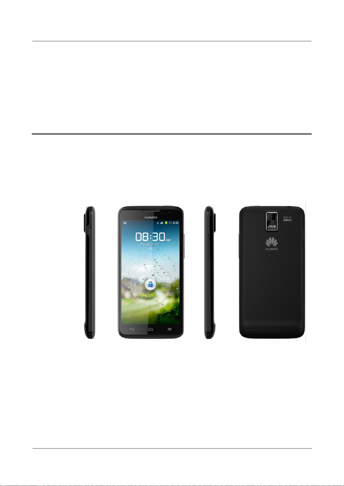
1.1 Appearance
Figure 1-1 shows U9500.
Figure 1-1 U9500
1 Product Overview
1.2 Features
Table 1-1 lists the product features.
U9500 Maintenance Guide
1 Product Overview
Issue 1.2 (2012-6-30)
Huawei Proprietary and Confidential
Copyright © Huawei Technologies Co., Ltd.
2
Table 1-1 U9500 product features
Item
Description
Type
Touchscreen smartphone
Dimensions (H x W x D)
129.9 mm x 64.9 mm x 8.9 mm (5.11 in. x 2.56 in. x 0.35 in.)
Working band
GSM/GPRS/EDGE: 850/900/1800/1900 MHz
UMTS: W850/W900/AWS/W1900/W2100 MHz
HSPA+: downlink: 21 Mbit/s; uplink: 5.76 Mbit/s
Weight (with battery)
About 132g
Description
WCDMA/GSM dual mode
Operating platform
OMAP4460+XMM 6260
Operating system: Android 4.0
Memory
8 GB ROM +1 GB RAM
Interface
Micro USB (for charging and data connection), 3.5 mm headset jack, and MHL
interface
Battery
1800 mAh Li-ion battery
Display
Size: 4.5 inches
Type: TFT
Resolution: 1280 x 720 pixels (HD)
microSD card
Supports a maximum of 32 GB microSD card.
Antenna
Built-in antenna
Camera
Rear camera: 8 megapixels, with dual LED flashlight
Front camera: 1.3 megapixels
Bluetooth
Bluetooth 3.0
Wi-Fi
802.11b/g/n
GPS
GPS, AGPS
FM
Supported
Outstanding features
WCDMA/GSM
Android 4.0
4.5-inch HD IPS+ TFT capacitive touch screen
1800 mAh battery
8.0 megapixel BSI rear camera (automatic focus+dual flashlight)
1.3 megapixel front camera
1080p HD video recording and playback
MHL to HDMI output
Dolby surround stereo audio
earSmart™ sound processor

U9500 Maintenance Guide
1 Product Overview
Issue 1.2 (2012-6-30)
Huawei Proprietary and Confidential
Copyright © Huawei Technologies Co., Ltd.
3
Item
Description
Dual microphone noise reduction
Gravity sensitive, proximity sensitive, light sensitive, and gyroscope
Bluetooth 3.0, FM, and GPS/AGPS/GLONASS
High-speed WCDMA 3G/WLAN access
Huawei's android app store: Hi-space
Rich services in Hi-space
U9500 Maintenance Guide
2 Applicable Scope and Precautions
Issue 1.2 (2012-6-30)
Huawei Proprietary and Confidential
Copyright © Huawei Technologies Co., Ltd.
4
2 Applicable Scope and Precautions
ESD is the main cause of damage to electrostatic-sensitive components. Each
ASC must exercise caution to avoid ESD damage and comply with the ESD
protection requirements in this manual.
2.1 Applicable Scope
This document provides repair instructions for technicians at service centers authorized by
Huawei. This maintenance manual is confidential and accessible to authorized service centers
(ASCs) and authorized service providers (ASPs) only. While every effort has been made to
ensure the accuracy of this document, errors may still exist. If you find any errors or have any
suggestions, please contact Huawei's customer service.
2.2 Precautions
Only qualified technicians are allowed to perform repair and calibration.
Perform all operations in electrostatic discharge (ESD) rooms and wear ESD wrist straps
throughout the operations.
Ensure that all components, screws, and insulators are properly installed after repair and
calibration, and that all cables and wires are installed and connected correctly.
Ensure that the soldering is lead-free and compliant with eco-friendly requirements.
2.3 How to Obtain Product and Repair Information
To obtain product and maintenance information, visit Huawei website at:
http://www.huaweidevice.com/cn/technicaIndex.do.
U9500 Maintenance Guide
3 Exploded View
Issue 1.2 (2012-6-30)
Huawei Proprietary and Confidential
Copyright © Huawei Technologies Co., Ltd.
5
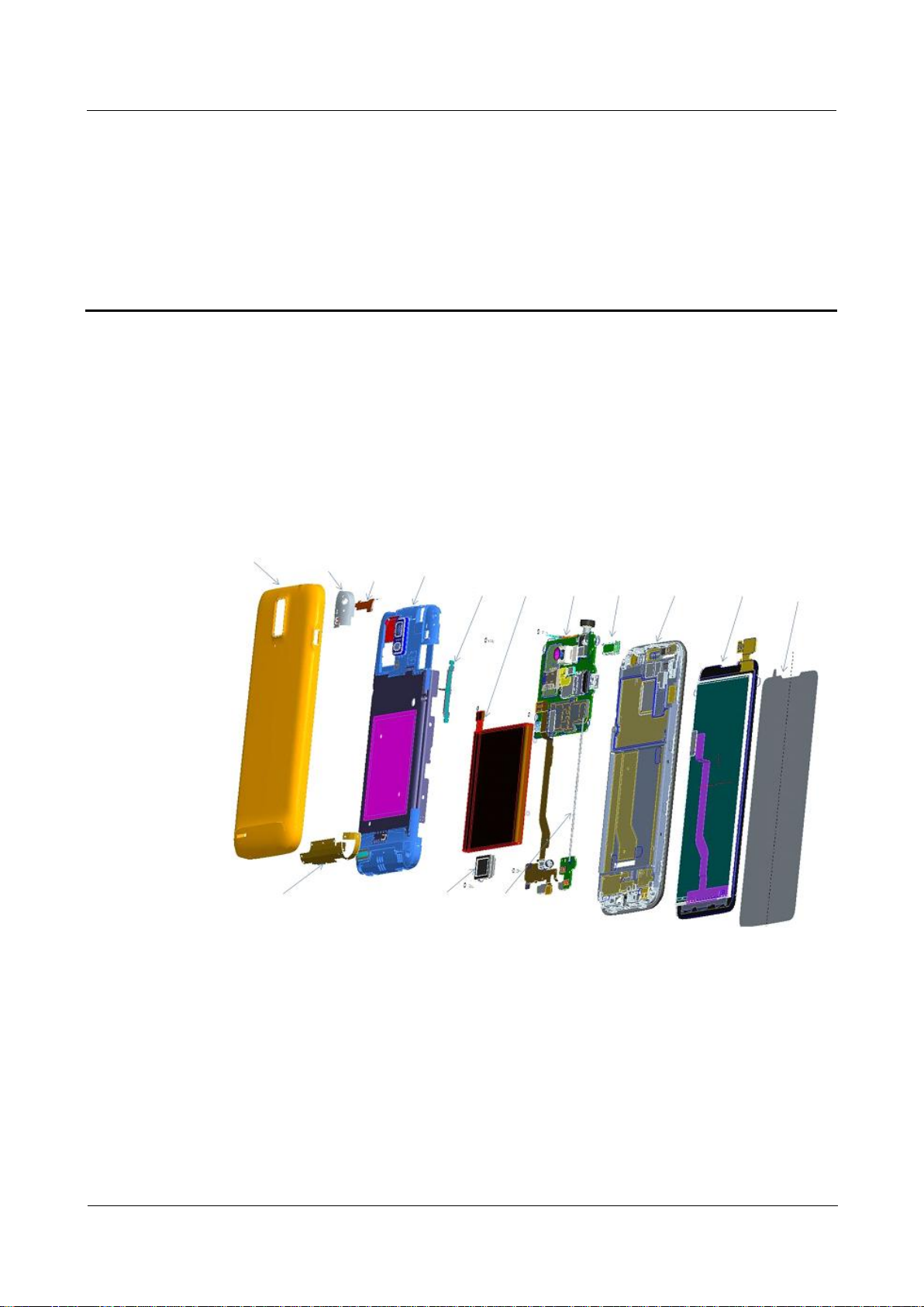
3.1 Exploded View
Battery cover
assembly
GPS
antenna
Bluetooth
antenna
Back cover
assembly
Side keys
Battery PCBA
Speaker
Front cover
assembly
TP
assembly
TP
protector
TP protector
Speaker Coaxial cable
The components listed in Figure 3-1 are structural parts of the phone, and cannot be used as
reference when requesting spare parts.
Figure 3-1 shows the U9500 exploded view.
Figure 3-1 U9500 exploded view
3 Exploded View
3.2 Component List
Table 3-1 lists the components of U9500.
U9500 Maintenance Guide
3 Exploded View
Issue 1.2 (2012-6-30)
Huawei Proprietary and Confidential
Copyright © Huawei Technologies Co., Ltd.
6
Table 3-1 Components of U9500
Part Number
Description
Quantity
03021JJY
Manufactured Board,U9500-1,HD1FRONTM,U9500-1Handset Main
Board(8G ROM/GSM 4
Band,W2100/W1900/W1700/W900/W850),Terminal Dedicated,2*2
1
03021KXY
Manufactured Board,U9500-1,HD1FRONTR,U9500 Receiver FPC(GSM 4
band,W2100/W1900/W1700/W850W/W900),1*1
1
03021KXV
Manufactured Board,U9500-1,HD1FRONTL,U9500 main FPC(GSM 4
band,W2100/W1900/W1700/W850W/W900),1*1
1
03021KXW
Manufactured Board,U9500,HD1FRONTFL,U9500 flash light FPC(GSM 4
band,W2100/W1900/W1700/W850W/W900),1*1
1
03021KXU
Manufactured Board,U9500-1,HD1FRONTA,U9500 antana board(GSM 4
band,W2100/W1900/W1700/W850W/W900),6*6
1
22020079
Speaker,8ohm,0.5w,11*15*3.5(Improved),Terminal Dedicated
1
22030044
Receiver,32ohm,6*15*2.0mm,wideband,Terminal Dedicated
1
02230MAN
U9500,Black A_Cover+LCD+TouchLens
1
02230MAP
U9500,White A_Cover+LCD+TouchLens
1
23060074
Camera Module Group,CMOS,1.3M-FF-Front-HD-BTB
1
23060093
Camera Module Group,1/3.2" CMOS/BSI,8M, 3264*2448,Terminal
Dedicated
1
27160960
Terminal Antenna,824MHz-960MHz/1710MHz-2170MHz,Better Than
-3dBi/Better Than -3dBi,Isotropic,line polarization,better than 3,4W,U9500-1
Main Antenna Fpc SAA
1
27160961
Terminal Antenna,2400MHz-2500MHz,Better Than -2dBi,Isotropic,Line
Polarization,Better Than 3,4W,U9500-1 Wifi Antenna Fpc SAA
1
27160962
GPS Antenna,1565MHz-1615MHz,Better Than -3dBi,Isotropic,Line
Polarization,Better Than 3,4W,U9500-1 GPS Antenna LDS SAA
1
04050406
Out Sourcing Cable,RF Coaxing Cable,75.6mm,Fit 14240433,Terminal
Dedicated
1
02230MAN is the black front cover assembly while 2230MAP is the white one. Select either in actual use.
NOTE
NOTE
The list of components is provided for reference only. This list is subject to change without notice. The
latest component list is available on Huawei's ITEM information system. If you have any questions,
please contact the local technical support center.

U9500 Maintenance Guide
4 Layout of Components on the PCBA
Issue 1.2 (2012-6-30)
Huawei Proprietary and Confidential
Copyright © Huawei Technologies Co., Ltd.
7
4 Layout of Components on the PCBA
4.1 Components on the PCBA
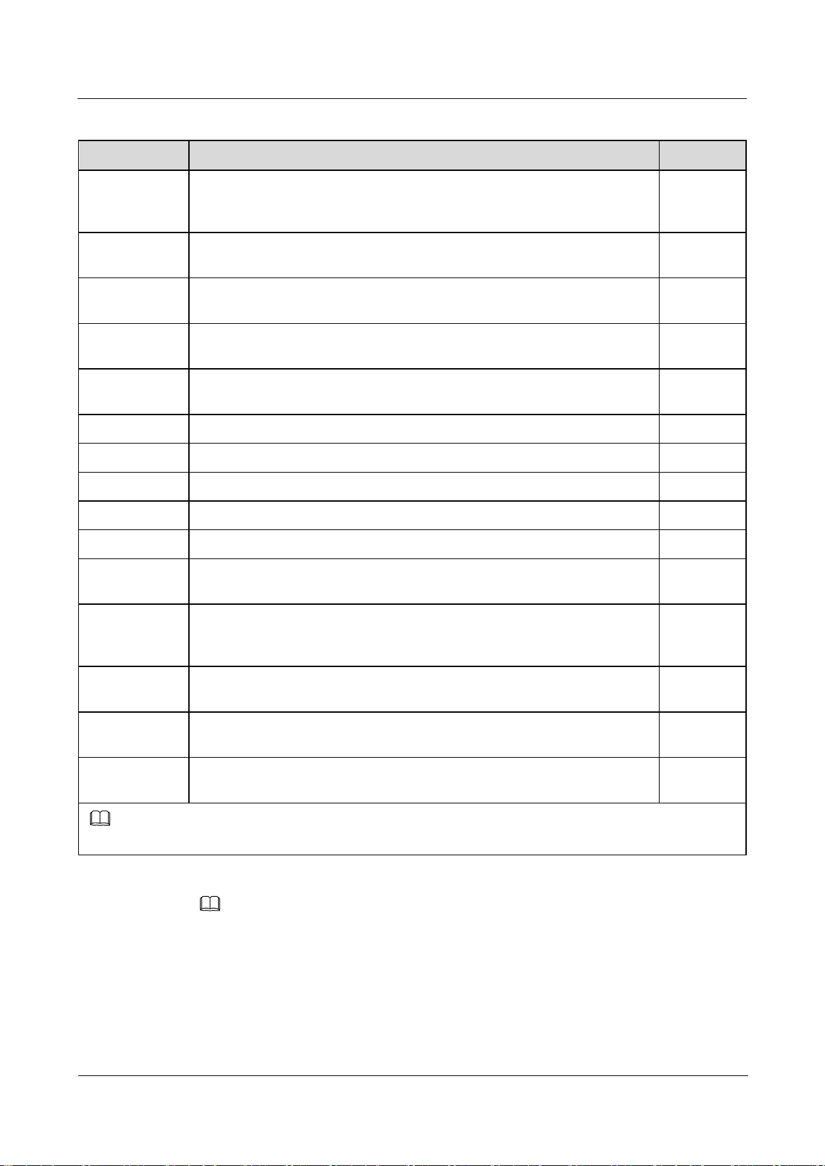
Figure 4-1 and Figure 4-2 show the components on the top and bottom sides of the PCBA and
failures that might occur because of damages to the components.
U9500 Maintenance Guide
4 Layout of Components on the PCBA
Issue 1.2 (2012-6-30)
Huawei Proprietary and Confidential
Copyright © Huawei Technologies Co., Ltd.
8
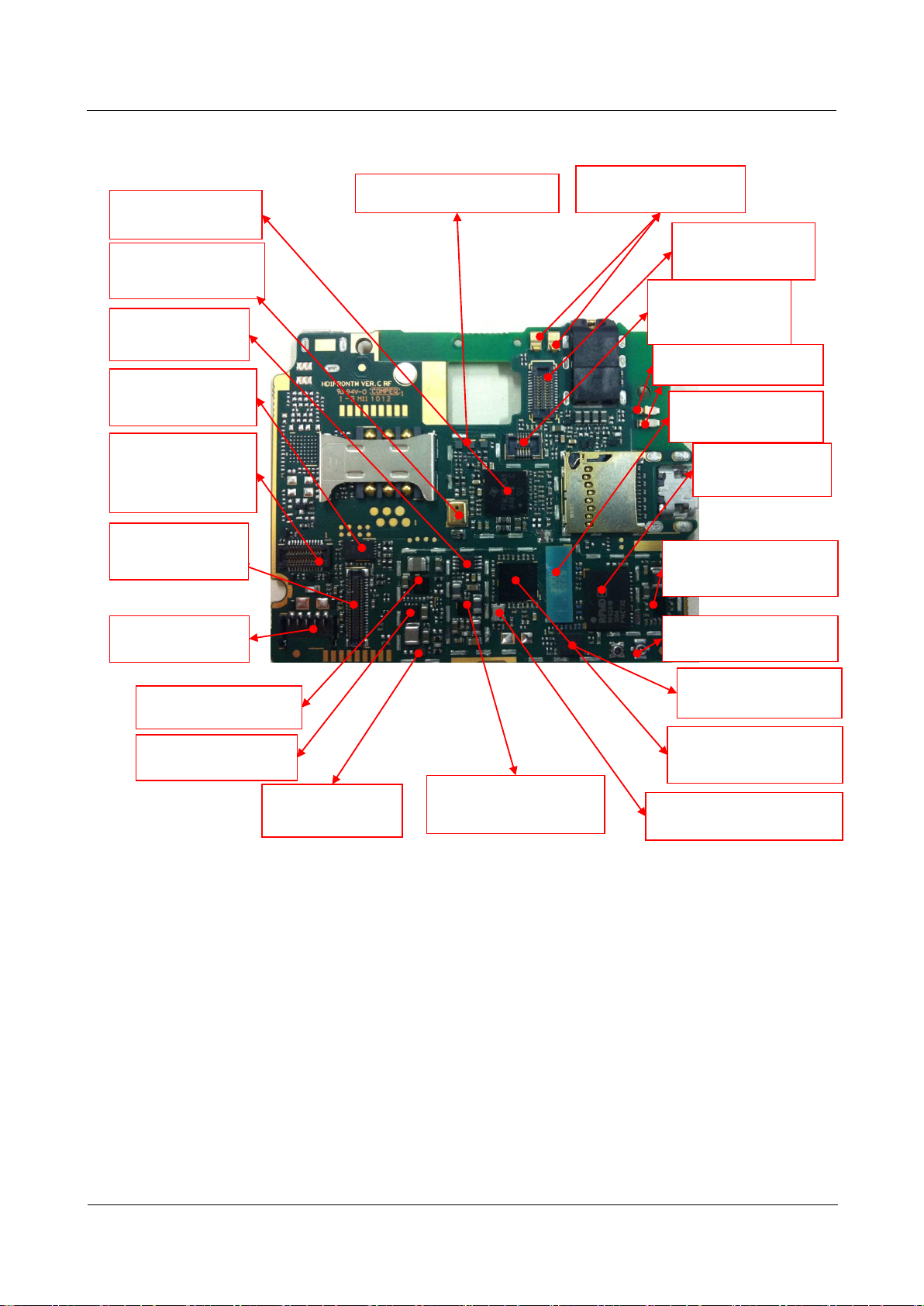
Figure 4-1 Components on the PCBA top side
VCXO900 Crystal oscillator( 26
MHz)
Failure symptom: power-on
failure
D1600 LCD backlight diode
Failure symptom: LCD backlight
failure
U2801 Audience
Failure symptom: Noise heard
by the remote end
U1600 LCD backlight power supply
chip Failure symptom: LCD backlight
failure
U1601 LCD power supply chip
Failure symptom: LCD failure
X900 Crystal oscillator( 32 kHz)
Failure symptom: power-on failure
U901 PM chip
Failure symptom: power-on
failure or excessive current
U2005 Compass chip
Failure symptom: compass
failure
U1800 Flashlight driver
Failure symptom: camera failure and torch
failure
J2201 HD1FRONTBTB connector
Failure symptom:
Receiver failure, power-on button failure, touch
panel failure, three-color light failure, and light
sensor failure
U2003 Gyroscope chip
Failure symptom: gyroscope failure
U3207/U3208 loadswitch
Failure symptom: camera
failure
U301/U301_POP Main chip/DDR
Failure symptom: power-on failure
U3801 Modem
Failure symptom: network registration
failure, network access failure, and call
set-up failure
TCX03601 GPS clock
Failure symptom: GPS failure
U501 Clock buffering chip
Failure symptom: power-on failure, codec
failure, or BT/WL/FM failure
U1102 8G EMMC
Failure symptom: power-on failure,
data storage or read failure
U3103 Level shifter chip
Failure symptom: MHL failure
U3106 Inverter
Failure symptom: MHL
failure
U3104 3.3 V LDO
Failure symptom: MHL failure
J1500 Headset jack
Failure symptom: headset failure, FM failure
J3604 GPS antenna grounding
spring
Failure symptom: GPS failure
U3601 GPS chip
Failure symptom: GPS failure
Z3599 Filter
Failure symptom: no signals on
BT/WL
U3501 RF switch
Failure symptom: network
registration failure and network
access failure
U3401 FM/BT/WL three-in-one chip
Failure symptom: FM/BT/WL failure
U1901 Charging chip
Failure symptom: charging
failure
U3102 USB switch
Failure symptom: USB connection
failure
U3101 MHL chip
Failure symptom: MHLfailure
U1900 USB switch
Failure symptom: MHL failure and
USB connection failure
U3105 DC-DC
Failure symptom: camera failure
U2004 Acceleration sensor chip
Failure symptom: accelerometer failure
U2401 Tri-color light control chip
Failure symptom: light failure
J1801 Secondary camera
BTB connector
Failure symptom: camera
failure
U9500 Maintenance Guide
4 Layout of Components on the PCBA
Issue 1.2 (2012-6-30)
Huawei Proprietary and Confidential
Copyright © Huawei Technologies Co., Ltd.
9
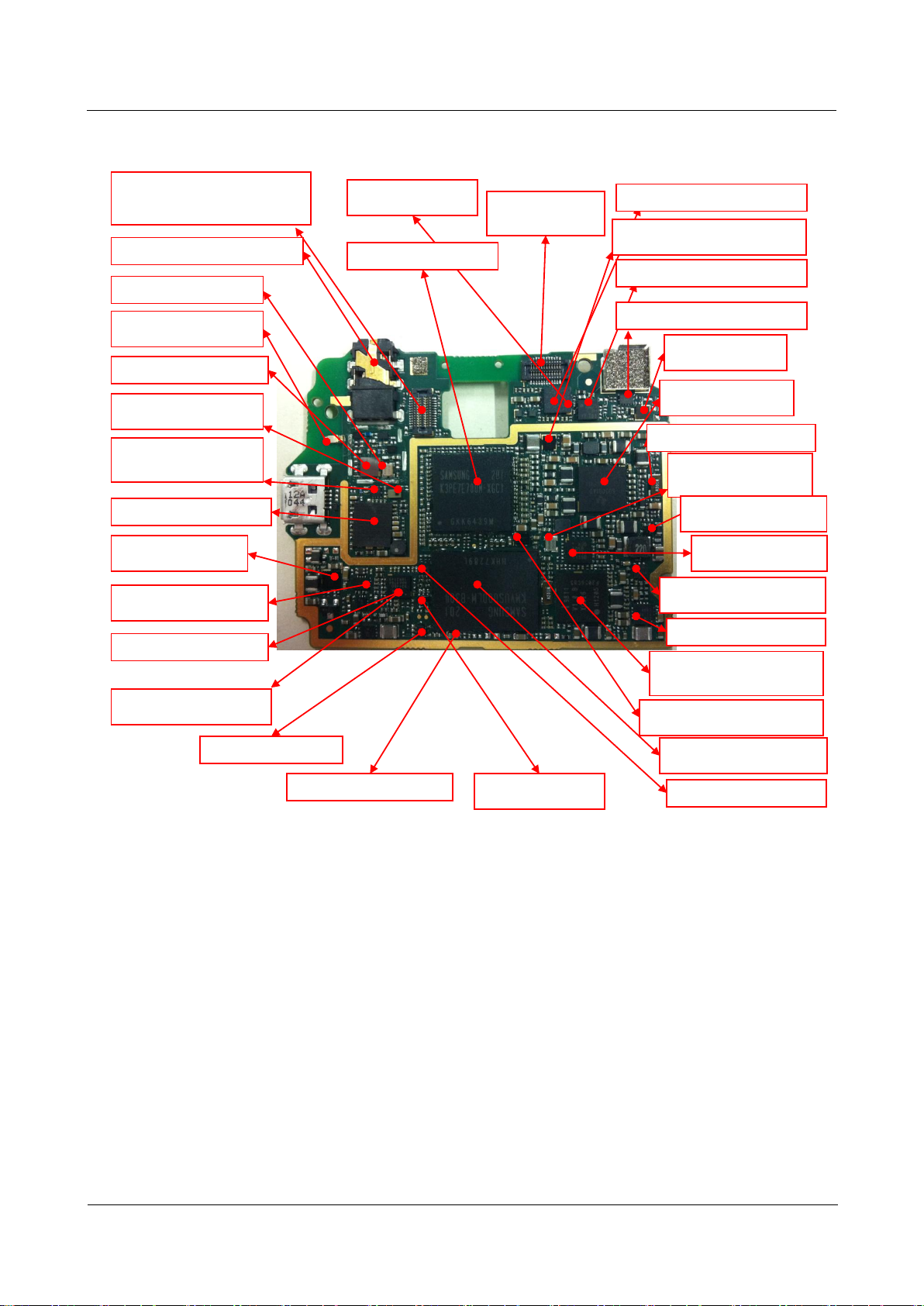
Figure 4-2 Components on the PCBA bottom side
U4704RFPA
Failure symptom:
network connection failure
U4801 RFPA power supply chip
Failure symptom:network
connection failure
J4710RFcoaxial connector
Failure symptom:network
connection failure
U4702 RFduplexer
Failure symptom: network
connection failure
J3602/3603 GPS antenna
spring
Failure symptom:GPS failure
J2202Flashlight BTB
connector
Failure symptom:
flashlight failure and torch
failure
J1800Rear camera BTB
connector
Failure symptom:camera
failure
J3503/J3504Bluetooth/WL
antenna spring
Failure symptom:no signals
U3203/U3204/U3205Load switch
Failure symptom:camera failure
MIC1402 Secondary
microphone
Failure symptom:no
loopback on the secondary
microphone
U4703 RF switch
Failure symptom:network
connection failure
U4701Dual-mode RF
transceiver chip
Failure symptom: network
access failure
U4708 RFclock(26 MHz)
Failure symptom:network access
failure
U3206Load switch
Failure symptom:
camera failure
U1201Codec chip
Failure symptom:audio
failure
U401Dual input and
gate
Failure symptom:power-
on failure
U1301 Energy meter chip
Failure symptom:power-
on failure and power
measurement failure
J2203Main FPC BTB
connector
Failure symptom:side key
failure, vibrator failure, main
microphone failure, and
speaker failure
J1601 LCD BTB
connector
Failure symptom: LCD
failure
J1301Battery connector
Failure symptom:power-
on failure
U902 AP energy meter
Failure symptom:power-on
failure or high temperature
U3201 2.85 V DCDC
Failure symptom:camera
failure
U4802Transceiver power supply
chip
Failure symptom:network
registration failure
U9500 Maintenance Guide
5 Software Upgrade
Issue 1.2 (2012-6-30)
Huawei Proprietary and Confidential
Copyright © Huawei Technologies Co., Ltd.
10
5.1 Upgrade Preparation
Category
Item
Remarks
Upgrade
environment
Computer
Operating system: Windows 2000, Windows
XP, or Windows 7
microSD card
Available space: > 1 GB
Battery
Remaining power: > 20%
Upgrade file
update.app
This version is provided for reference only.
Please download the latest version when
upgrading the software.
Upgrade using the
microSD card
Normal upgrade
Forcible upgrade
Prepare the items listed in Table 5-1.
Table 5-1 Items to be prepared before a software upgrade
5 Software Upgrade
5.2 Upgrade Using a microSD Card
5.2.1 Normal Upgrade
To perform a normal upgrade, perform the following steps:
Step 1 Create a dload folder in the microSD card's root directory.
Step 2 Copy the upgrade file update.app to the dload folder.
Step 3 Install the microSD card to the phone and power the phone on.
Step 4 Enter *#*#2846579#*#* in dialing mode. Choose ProjectMenu > Upgrade > microSD card
upgrade, and touch Confirm.

U9500 Maintenance Guide
5 Software Upgrade
Issue 1.2 (2012-6-30)
Huawei Proprietary and Confidential
Copyright © Huawei Technologies Co., Ltd.
11
The upgrade progress is displayed on the screen.
After the upgrade is completed, the phone automatically restarts.
If the upgrade fails, the upgrade page remains on the screen, and an upgrade failure message
is displayed.
---End
5.2.2 Forcible Upgrade
If the mobile phone fails to start, use the following method to perform a forcible upgrade:
Step 1 Create a dload folder in the microSD card's root directory.
Step 2 Copy the upgrade file update.app to the dload folder.
Step 3 Install the microSD card to the phone.
Step 4 Press the volume up, volume down, and Power keys concurrently for more than 3 seconds to
power on the phone.
The phone starts to upgrade. The upgrade process is displayed on the screen.
After the upgrade is complete, the phone automatically restarts.
If the upgrade fails, the upgrade page remains on the screen, and an upgrade failure message
is displayed.
---End
5.3 Upgrade Failure Troubleshooting
If you fail to upgrade the phone using a microSD card, perform the following steps to
troubleshoot the failure:
Step 1 Check whether the upgrade file is correct.
Step 2 Check whether the upgrade file is stored in the right directory.
Step 3 Check whether the upgrade method is correct.
Step 4 Check whether the microSD card functions properly.
Step 5 Perform the upgrade again.
---End
U9500 Maintenance Guide
6 Repair Tools
Issue 1.2 (2012-6-30)
Huawei Proprietary and Confidential
Copyright © Huawei Technologies Co., Ltd.
12
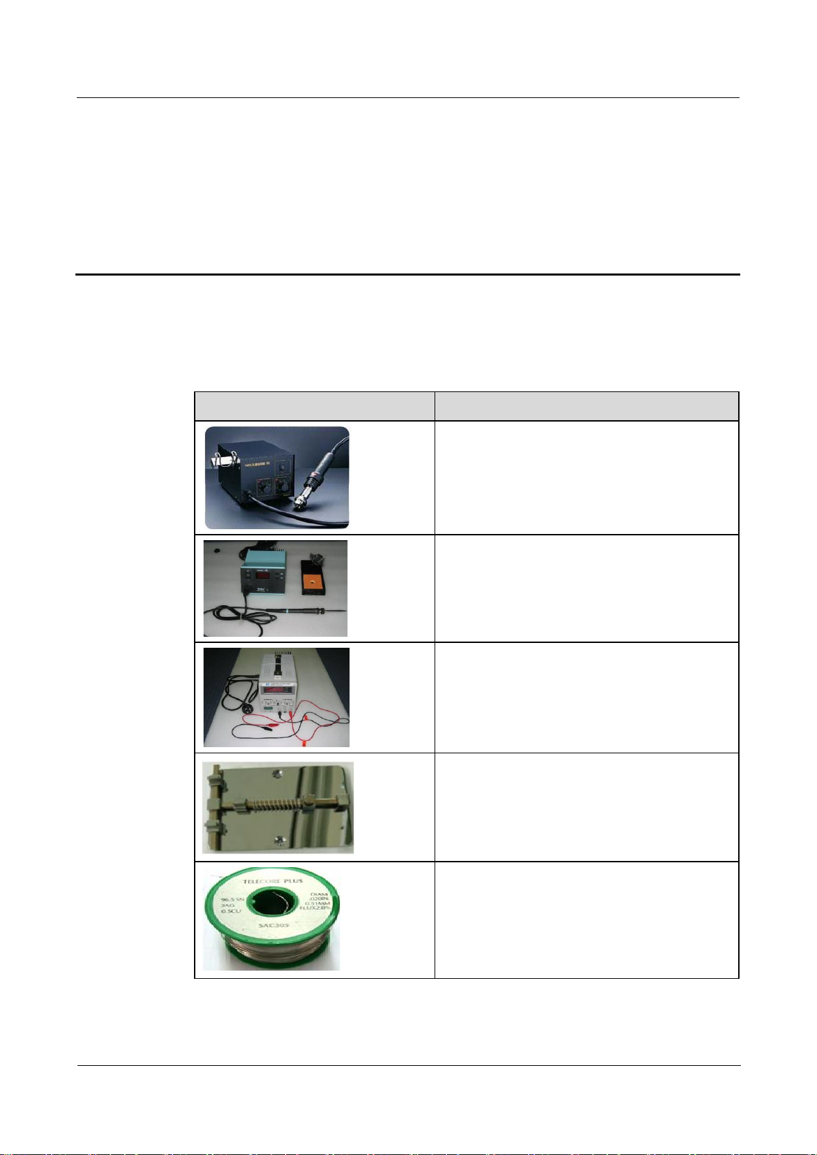
Table 6-1 lists the repair tools.
Picture
Description
Name: heat gun
Usage: Heats components
Name: soldering iron
Usage: solders components
Name: DC power supply
Usage: powers the phone
Name: soldering fixture
Usage: secures the PCBA
Name: lead-free solder wire
Usage: soldering material
Table 6-1 Repair tools
6 Repair Tools
U9500 Maintenance Guide
6 Repair Tools
Issue 1.2 (2012-6-30)
Huawei Proprietary and Confidential
Copyright © Huawei Technologies Co., Ltd.
13
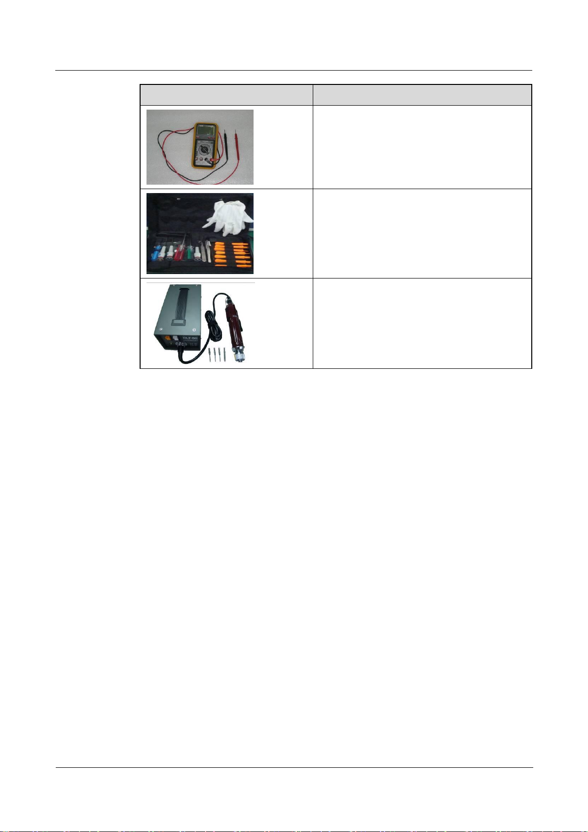
Picture
Description
Name: digital multimeter
Usage: measurement
Name: toolkit
Usage: assembling and disassembling
Name: electric screwdriver
Usage: fastens and removes screws
U9500 Maintenance Guide
7 Disassembly Procedure
Issue 1.2 (2012-6-30)
Huawei Proprietary and Confidential
Copyright © Huawei Technologies Co., Ltd.
14
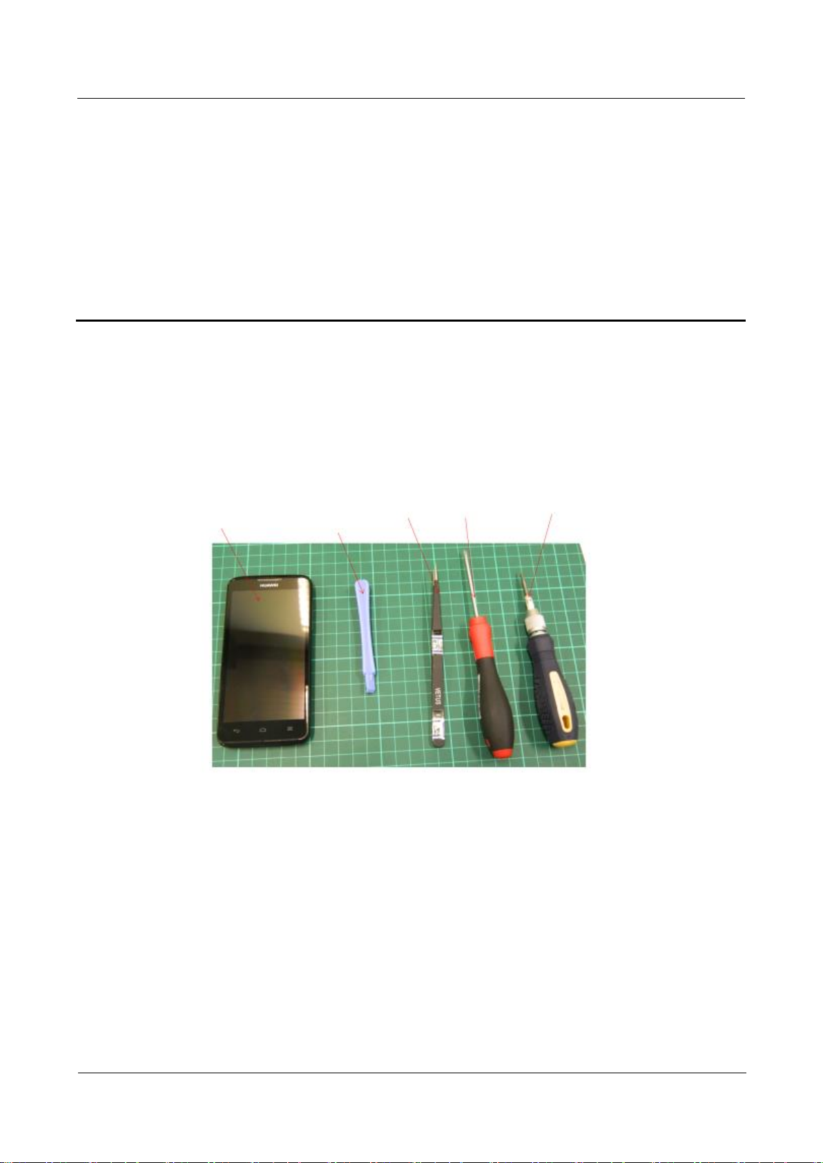
7 Disassembly Procedure
U9500
Nonmetallic
stick
Tweezers
Phillips
screwdriver
Hexagon
screwdriver
7.1 Disassembly Preparation
Figure 7-1 shows the disassembly tools.
Figure 7-1 Disassembly tools
7.2 Disassembly Procedure
Wear ESD gloves when you remove the PCBA, antenna board, FPCs, and other electronic
components.
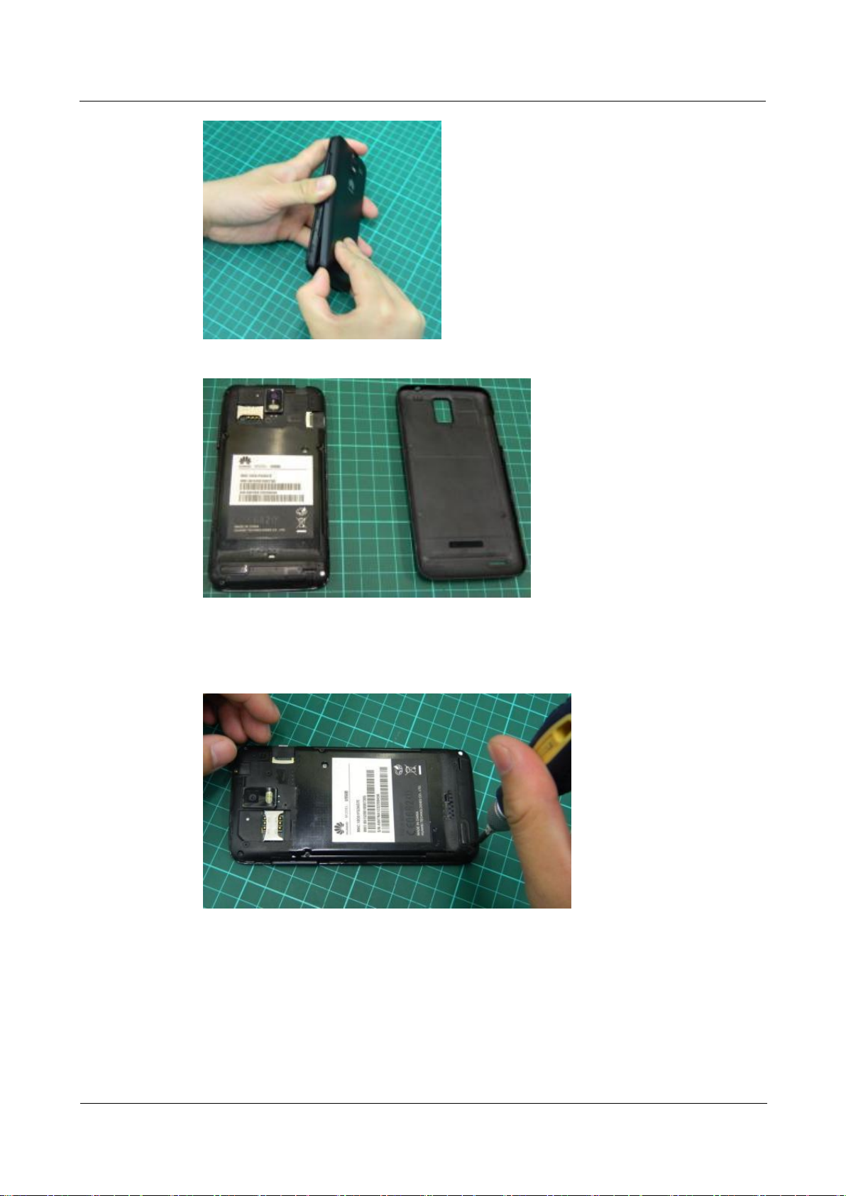
To disassemble a U9500, perform the following operations:
Step 1 Remove the battery cover.
U9500 Maintenance Guide
7 Disassembly Procedure
Issue 1.2 (2012-6-30)
Huawei Proprietary and Confidential
Copyright © Huawei Technologies Co., Ltd.
15
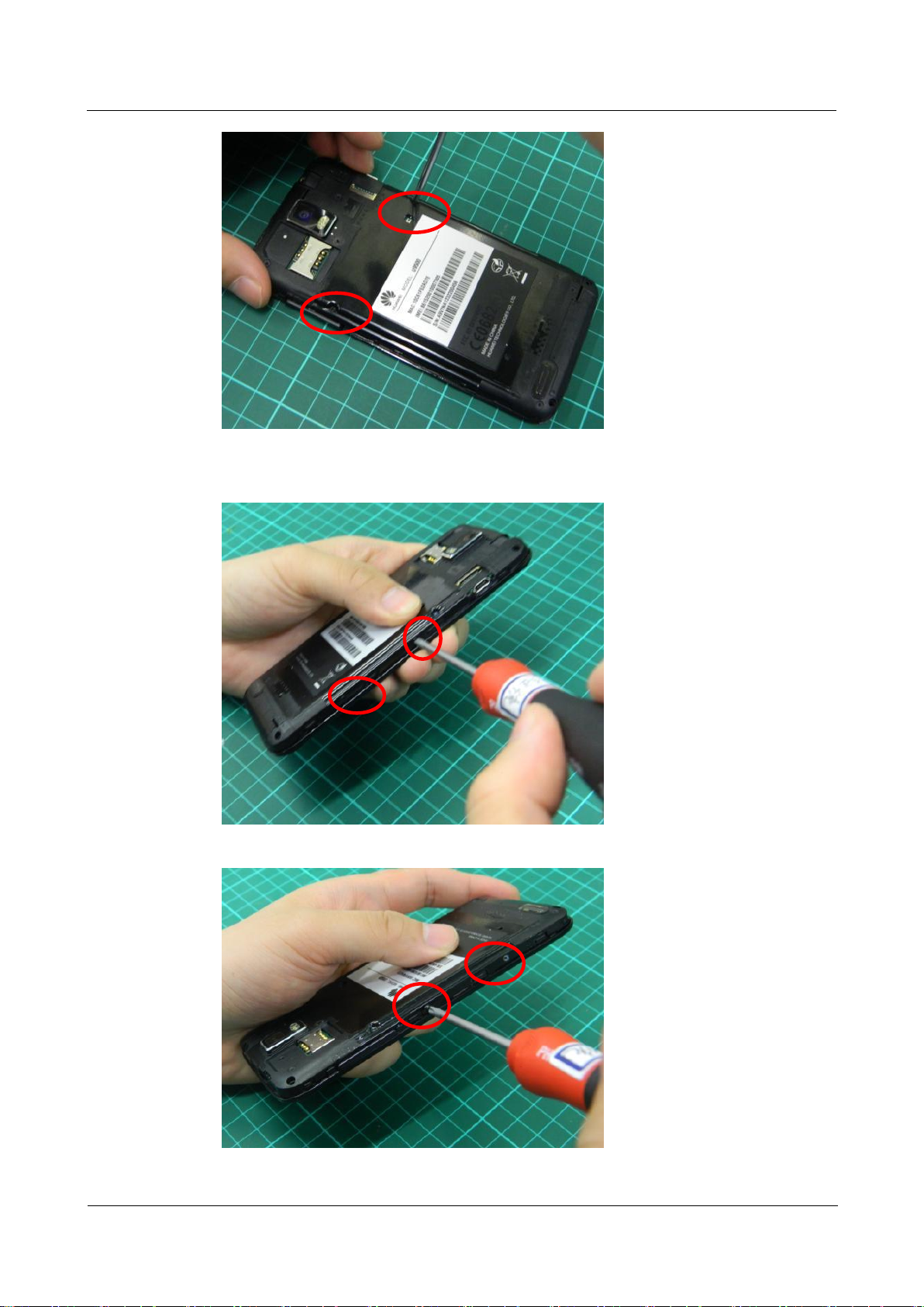
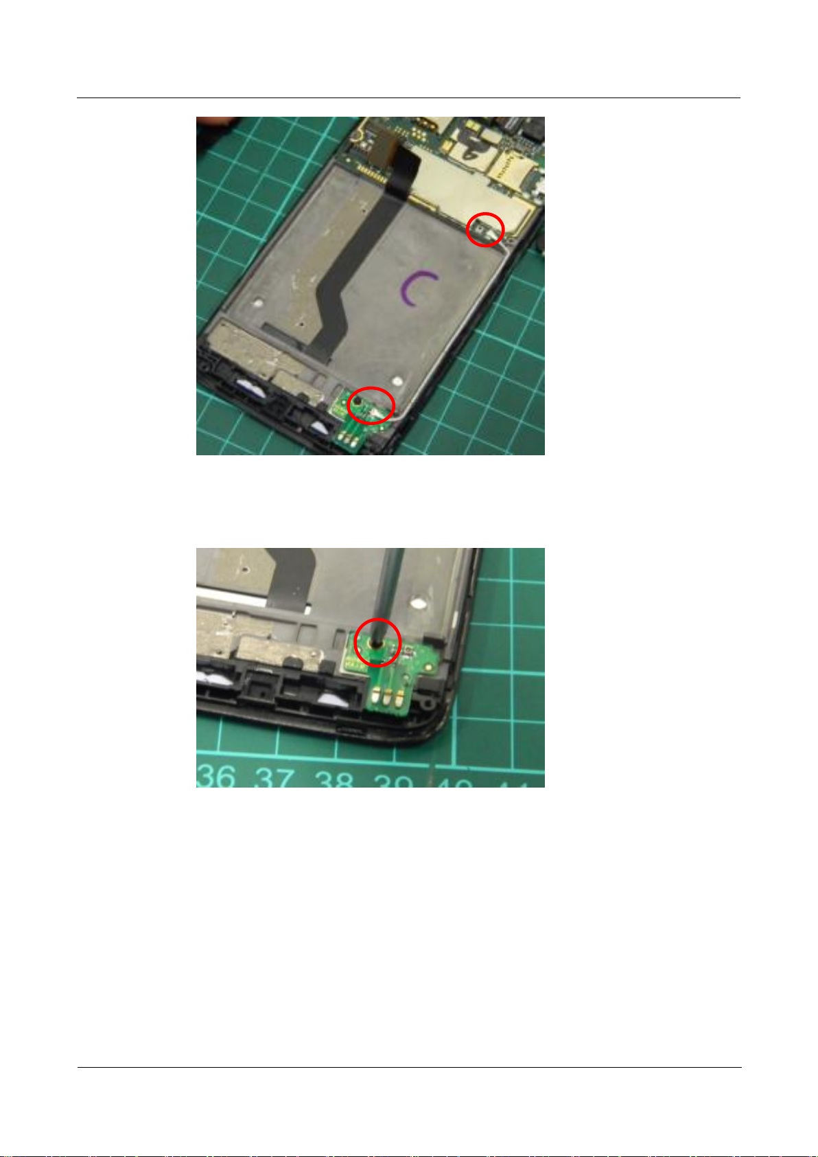
Step 2 Remove the screws in the back over.
1. Remove the hexagon screws in the four corners.
2. Remove the two Phillips screws in the central part.
U9500 Maintenance Guide
7 Disassembly Procedure
Issue 1.2 (2012-6-30)
Huawei Proprietary and Confidential
Copyright © Huawei Technologies Co., Ltd.
16
3. Remove the four Phillips screws on both sides of the phone.

U9500 Maintenance Guide
7 Disassembly Procedure
Issue 1.2 (2012-6-30)
Huawei Proprietary and Confidential
Copyright © Huawei Technologies Co., Ltd.
17
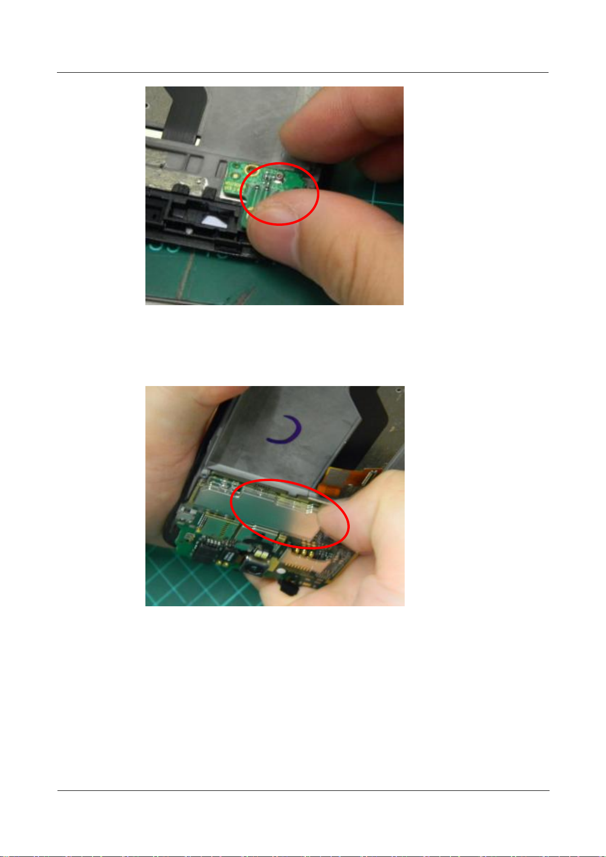
Step 3 Remove the back cover.
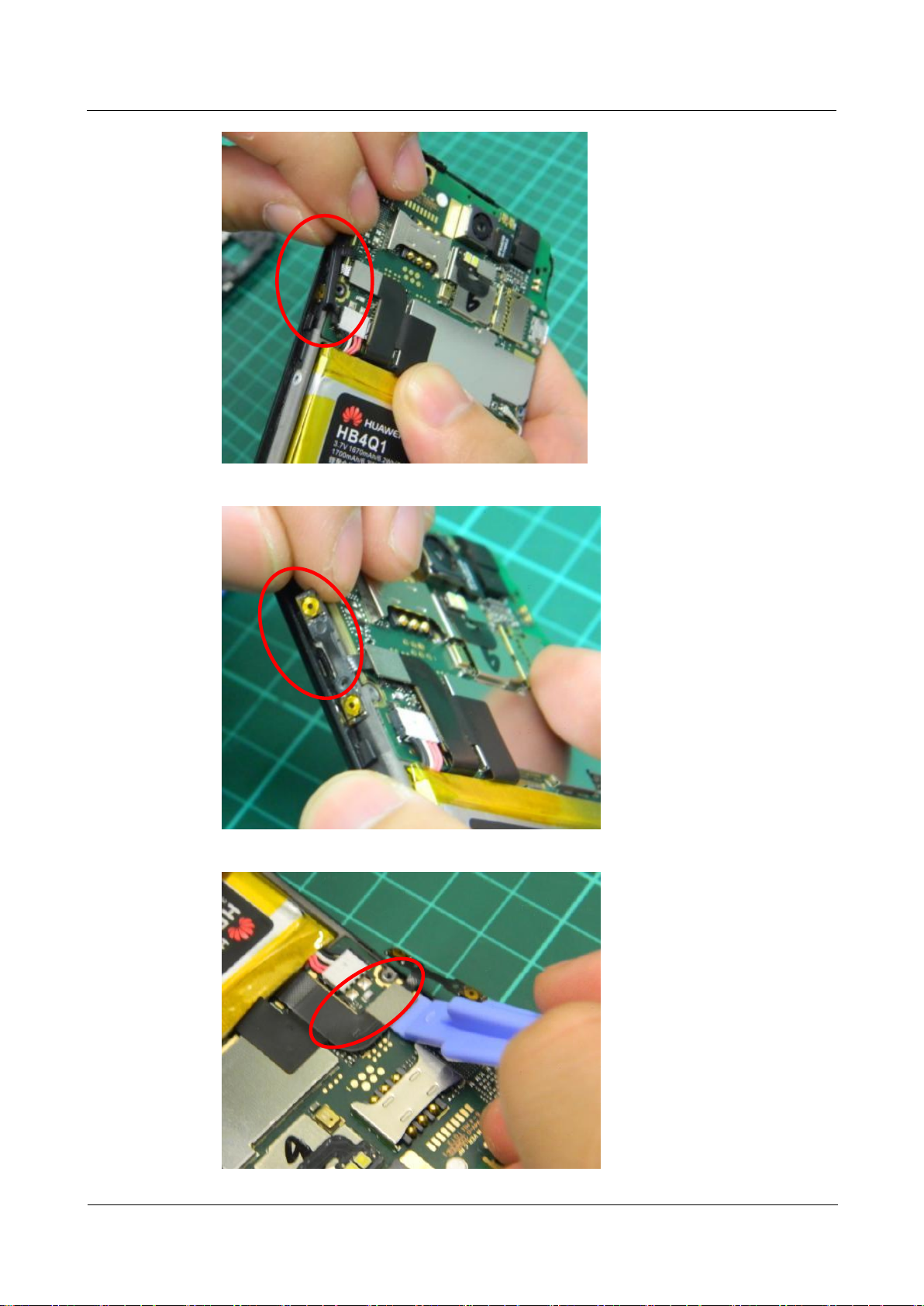
Step 4 Remove the volume keys and relevant FPCs.
U9500 Maintenance Guide
7 Disassembly Procedure
Issue 1.2 (2012-6-30)
Huawei Proprietary and Confidential
Copyright © Huawei Technologies Co., Ltd.
18
U9500 Maintenance Guide
7 Disassembly Procedure
Issue 1.2 (2012-6-30)
Huawei Proprietary and Confidential
Copyright © Huawei Technologies Co., Ltd.
19
NOTE
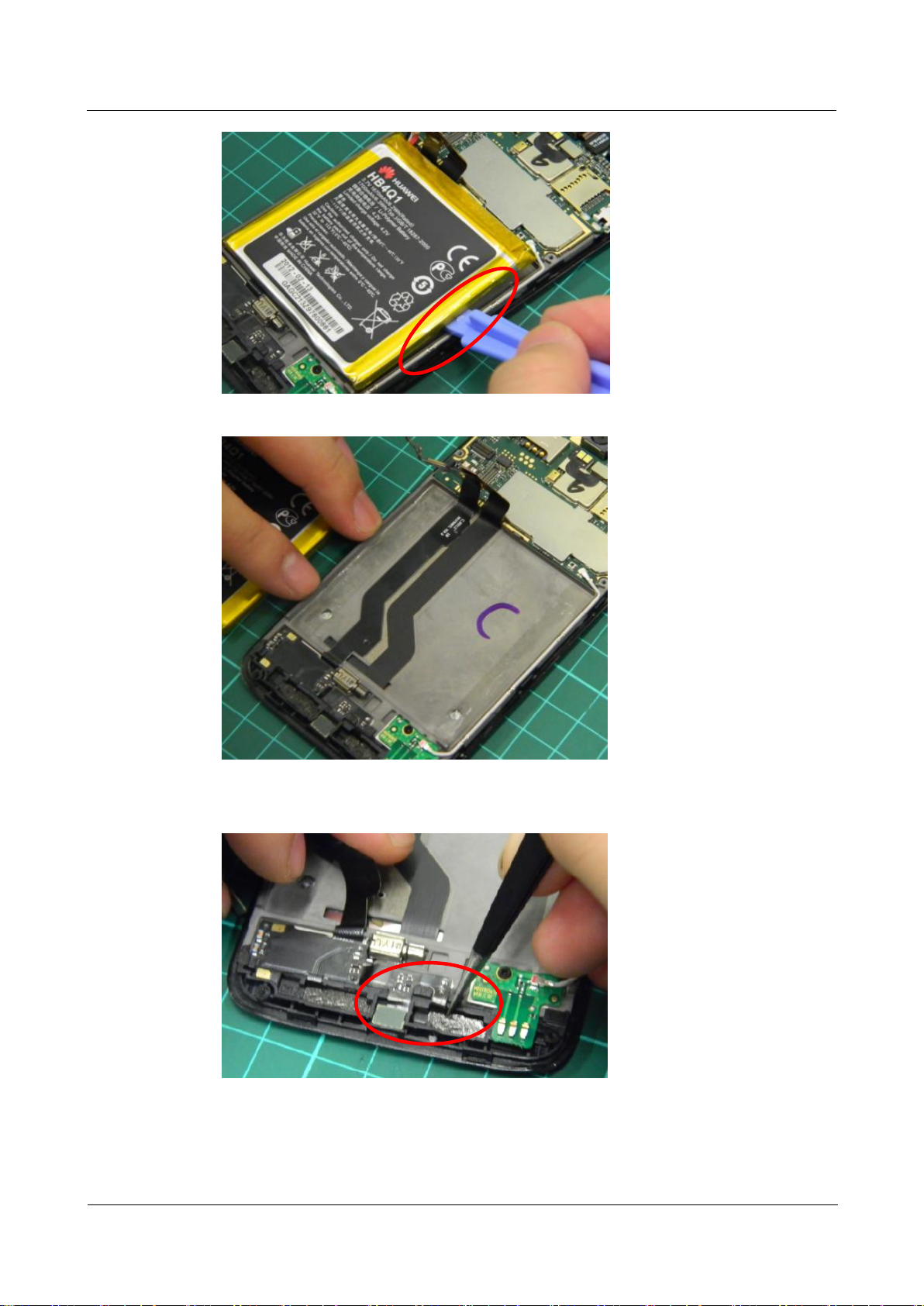
Step 5 Remove the battery.
The battery is packed using aluminum film and adhesive tapes. Exercise caution. Do not damage the
film or the adhesive tapes. The battery cannot be used any more after being disassembled.
U9500 Maintenance Guide
7 Disassembly Procedure
Issue 1.2 (2012-6-30)
Huawei Proprietary and Confidential
Copyright © Huawei Technologies Co., Ltd.
20
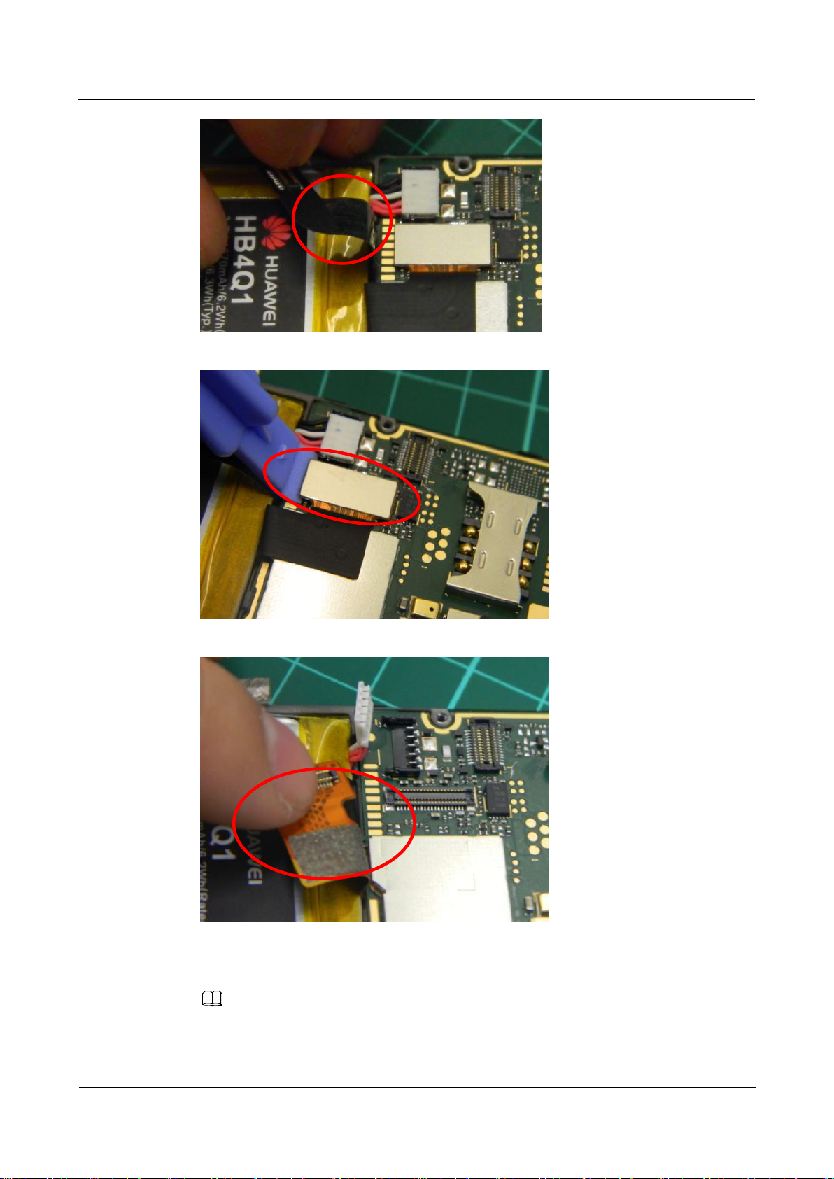
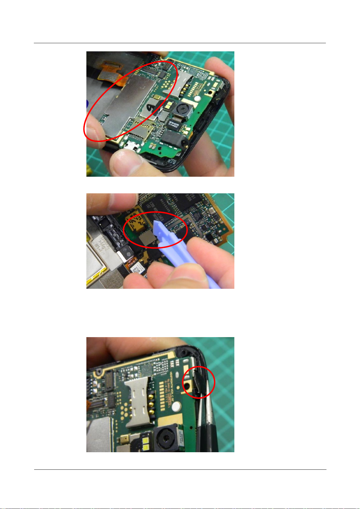
Step 6 Remove the keypad backlight.
U9500 Maintenance Guide
7 Disassembly Procedure
Issue 1.2 (2012-6-30)
Huawei Proprietary and Confidential
Copyright © Huawei Technologies Co., Ltd.
21
Step 7 Remove the primary microphone.
U9500 Maintenance Guide
7 Disassembly Procedure
Issue 1.2 (2012-6-30)
Huawei Proprietary and Confidential
Copyright © Huawei Technologies Co., Ltd.
22
Step 8 Remove the coaxial cable.
U9500 Maintenance Guide
7 Disassembly Procedure
Issue 1.2 (2012-6-30)
Huawei Proprietary and Confidential
Copyright © Huawei Technologies Co., Ltd.
23
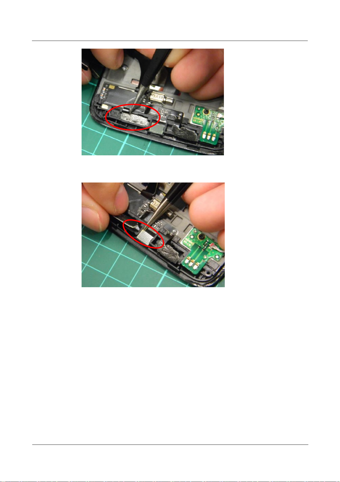
Step 9 Remove the antenna board.
Remove the antenna board screws and then the antenna board.
U9500 Maintenance Guide
7 Disassembly Procedure
Issue 1.2 (2012-6-30)
Huawei Proprietary and Confidential
Copyright © Huawei Technologies Co., Ltd.
24
Step 10 Remove the PCBA.
Release the PCBA from the buckles, pull the PCBA downward to remove it, and disconnect
the receiver BTB connector.
U9500 Maintenance Guide
7 Disassembly Procedure
Issue 1.2 (2012-6-30)
Huawei Proprietary and Confidential
Copyright © Huawei Technologies Co., Ltd.
25
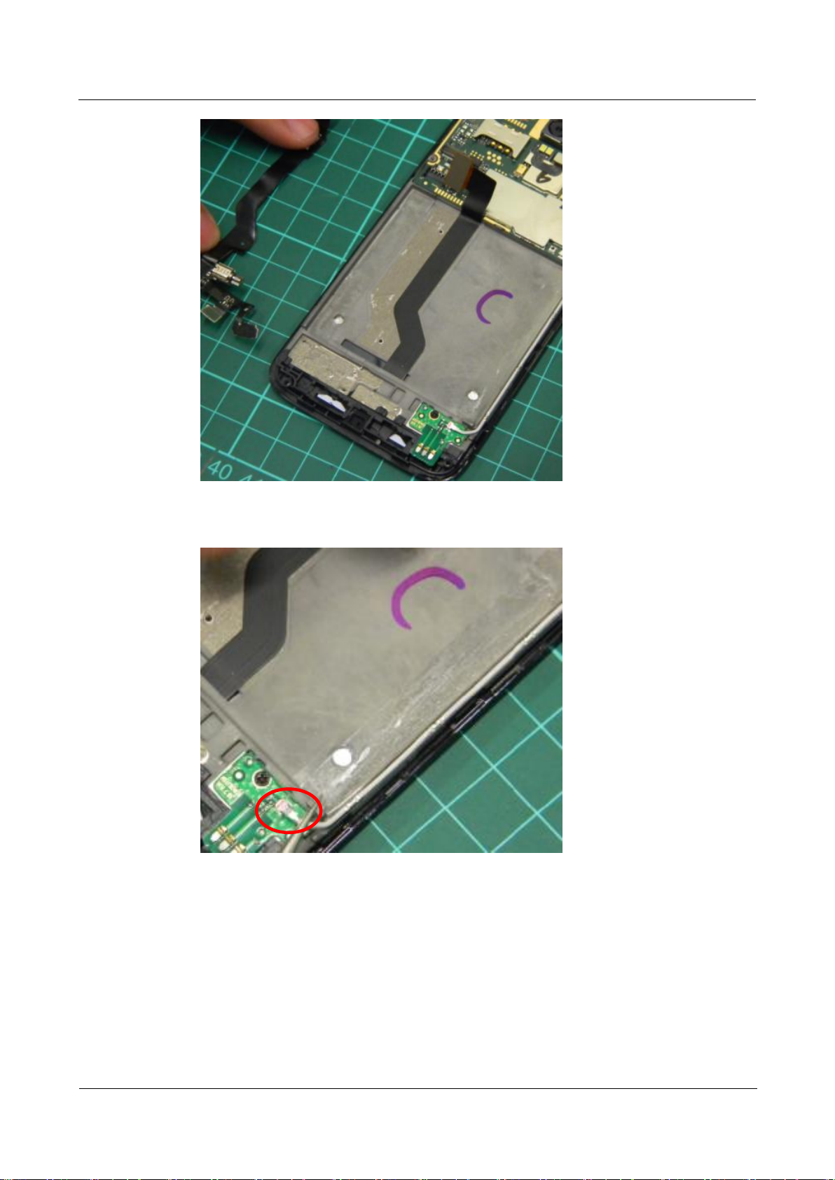
Step 11 Remove the receiver support.
Use the tweezers to separate the Power key FPC from the PCBA and pry the receiver support
off.
 Loading...