

Huawei U9200 Maintenance Manual
Prepared by
Date
2012-03-08
Reviewed by
Date
Approved by
Date
U9200 Maintenance Manual
V1.0
Huawei Technologies Co., Ltd.
All rights reserved.
U9200 Maintenance Manual
INTERNAL
(2012-06-13)
Huawei Proprietary and Confidential
Copyright © Huawei Technologies Co., Ltd.
Page 2 of 80
Change History
Date
Version
Change Reason
Section No.
Description
Author
2012-03-08
V1.0
Li Xianxi

U9200 Maintenance Manual
INTERNAL
(2012-06-13)
Huawei Proprietary and Confidential
Copyright © Huawei Technologies Co., Ltd.
Page 3 of 80
Contents
1 Product Introduction .................................................................................................................... 6
1.1 Appearance ....................................................................................................................................................... 6
1.2 Features ............................................................................................................................................................ 6
2 Applicable Scope and Precautions ............................................................................................ 8
2.1 Applicable Scope .............................................................................................................................................. 8
2.2 Precautions ....................................................................................................................................................... 8
2.3 How to Obtain Product and Repair Information .............................................................................................. 8
3 Exploded View............................................................................................................................... 9
3.1 Exploded View ................................................................................................................................................. 9
3.2 Component List ................................................................................................................................................ 9
4 Layout of Components on Main Board................................................................................... 11
4.1 List of Components on Main Board ............................................................................................................... 11
5 Software Upgrade ....................................................................................................................... 16
5.1 Upgrade Preparation ....................................................................................................................................... 16
5.2 microSD Card Upgrade .................................................................................................................................. 16
5.2.1 Normal Upgrade .................................................................................................................................... 16
5.2.2 Forcible Upgrade .................................................................................................................................. 16
5.3 Troubleshooting .............................................................................................................................................. 17
6 Maintenance Tools ...................................................................................................................... 18
7 Disassembly Procedure .............................................................................................................. 20
7.1 Disassembly Procedure .................................................................................................................................. 20
8 Assembly Procedure ................................................................................................................... 28
8.1 Installing the Air Filter ................................................................................................................................... 28
8.2 Installing the Sub Board to the Front Cover ................................................................................................... 28
8.3 Installing the Touch Key FPC to the Front Cover .......................................................................................... 30
8.4 Wiping the Front Cover .................................................................................................................................. 31
8.5 Gluing TP Components .................................................................................................................................. 32
8.6 Pre-Pressing TP Components ......................................................................................................................... 32
8.7 Packing TP Components ................................................................................................................................ 33
8.8 Installing the REC-FPC to the Main Board .................................................................................................... 33

U9200 Maintenance Manual
INTERNAL
(2012-06-13)
Huawei Proprietary and Confidential
Copyright © Huawei Technologies Co., Ltd.
Page 4 of 80
8.9 Installing Bluetooth and GPS Supports .......................................................................................................... 34
8.10 Installing the Front Camera to the Main Board ............................................................................................ 34
8.11 Installing the Receiver and Pasting a Protective Film .................................................................................. 35
8.12 Installing the Main Board to the Front Cover .............................................................................................. 35
8.13 Installing the Rear Camera to the Front Cover ............................................................................................. 36
8.14 Installing the Coaxial Line to the Front Cover ............................................................................................. 37
8.15 Installing and Screwing the SPK Support .................................................................................................... 37
8.16 Installing and Pressing the Battery ............................................................................................................... 38
8.17 Installing and Screwing the Shielding Cover ............................................................................................... 38
8.18 Installing and Screwing the Rear Cover ....................................................................................................... 39
9 Troubleshooting Common Problems ...................................................................................... 40
9.1 Architecture Introduction ............................................................................................................................... 40
9.2 Power-On Failure ........................................................................................................................................... 46
9.2.1 Large Current (DC Power Supply)........................................................................................................ 46
9.2.2 Low Current (DC Power Supply) ......................................................................................................... 47
9.2.3 No Current (DC Power Supply) ............................................................................................................ 49
9.3 Charging Failure ............................................................................................................................................. 50
9.4 Display Failure ............................................................................................................................................... 52
9.5 Vibration Failure ............................................................................................................................................ 53
9.6 microSD Card Identification Failure .............................................................................................................. 54
9.7 USIM Card Identification Failure .................................................................................................................. 55
9.8 TP Failure ....................................................................................................................................................... 55
9.9 Touch Key Failure .......................................................................................................................................... 57
9.10 Proximity Sensor and Auto Light Sensor Failure ......................................................................................... 58
9.11 Acceleration Sensor Failure .......................................................................................................................... 58
9.12 Compass Sensor Failure ............................................................................................................................... 59
9.13 Camera Failure ............................................................................................................................................. 60
9.14 Audio Failure ................................................................................................................................................ 60
9.14.1 Speaker Failure ................................................................................................................................... 60
9.14.2 MIC Failure ......................................................................................................................................... 61
9.14.3 Receiver Failure .................................................................................................................................. 62
9.15 Headset Failure ............................................................................................................................................. 63
9.15.1 Headset Silence ................................................................................................... 错误!未定义书签。
9.15.2 No Transmission Through Headset ..................................................................................................... 64
9.16 Wi-Fi/Bluetooth Failure ............................................................................................................................... 65
9.17 FM Failure .................................................................................................................................................... 66
9.18 GPS Failure .................................................................................................................................................. 67
9.19 MHL Failure ................................................................................................................................................. 68
9.20 WCDMA RF Receiving Failure ................................................................................................................... 69
9.21 WCDMA RF Transmitting Failure ............................................................................................................... 71
9.22 GSM RF Receiving Failure .......................................................................................................................... 73

U9200 Maintenance Manual
INTERNAL
(2012-06-13)
Huawei Proprietary and Confidential
Copyright © Huawei Technologies Co., Ltd.
Page 5 of 80
9.23 GSM RF Transmitting Failure ...................................................................................................................... 75
10 Functional Test .......................................................................................................................... 77
10.1 Keypad Introduction ..................................................................................................................................... 77
10.2 MMI Test ...................................................................................................................................................... 77
10.3 Wi-Fi Test ..................................................................................................................................................... 80
10.4 Voice Call Test .............................................................................................................................................. 80
U9200 Maintenance Manual
INTERNAL
(2012-06-13)
Huawei Proprietary and Confidential
Copyright © Huawei Technologies Co., Ltd.
Page 6 of 80
1 Product Introduction
Item
Specifications
Phone type
Touchscreen smartphone
Dimensions (H x W x D)
7.69 mm x 129 mm x 64.8 mm
Working band
GSM/GPRS/EDGE: 850/900/1800/1900
UMTS: W850/W900/AWS/W1900/W2100
HSPA+: downlink 21 Mbps; uplink 5.76 Mbps
Weight
About 110 g
Technical standard
WCDMA/GSM
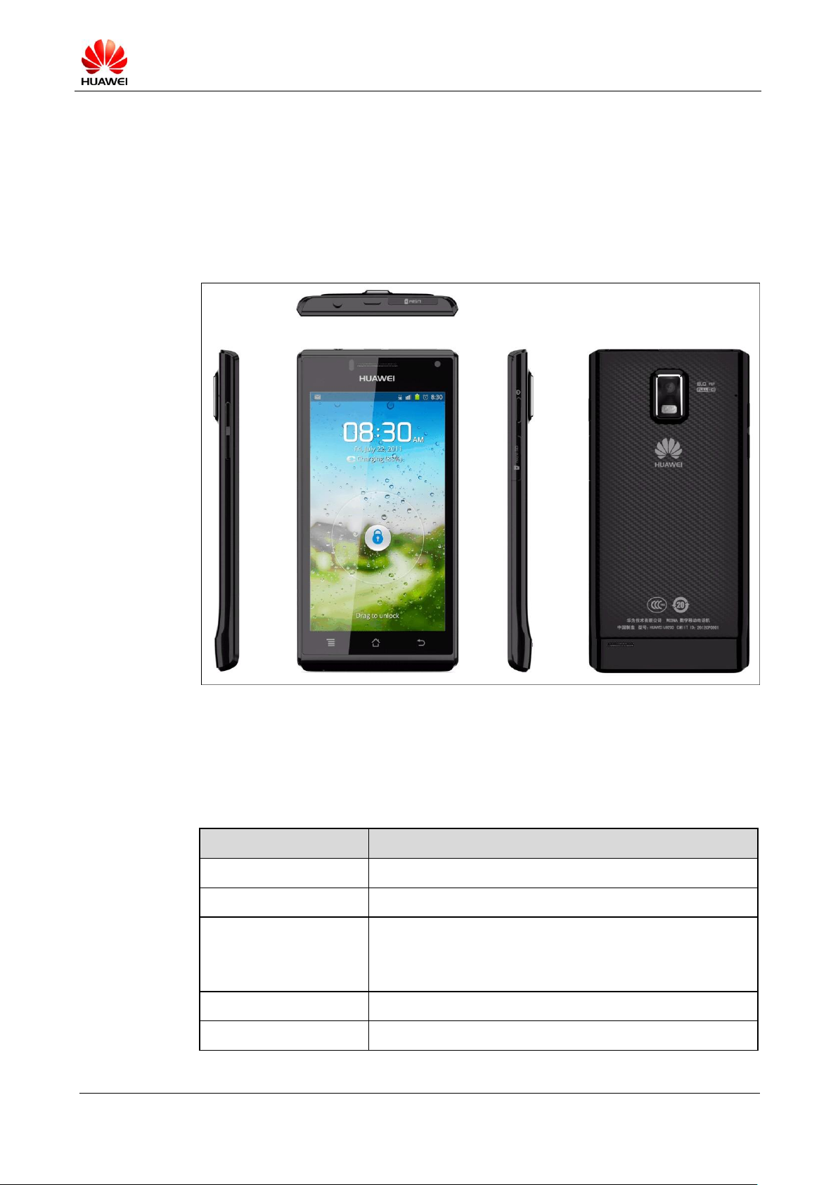
1.1 Appearance
Figure 1-1 shows the U9200.
Figure 1-1 U9200
1.2 Features
Table 1-1 lists the specifications of the U9200.
Table 1-1 Specifications of the U9200
U9200 Maintenance Manual
INTERNAL
(2012-06-13)
Huawei Proprietary and Confidential
Copyright © Huawei Technologies Co., Ltd.
Page 7 of 80
Item
Specifications
System platform
OMAP4460 + XMM 6260
OS: Android 4.0
Memory
4 GB ROM + 1 GB RAM
Ports
Micro USB (for charging and data transmission)
3.5 mm headset jack
MHL port;
Battery
1670 mAh Li-ion battery
Display
Size: 4.3 inches
Category: AMOLED
Resolution: 960 x 540 pixels (qHD)
Expansion card
Supports a maximum of 32 GB microSD card
Antenna
Built-in antenna
Camera
Rear camera: 8 megapixels, with dual LED flashlights
Front camera: 1.3 megapixels
Bluetooth
Bluetooth 3.0
Wi-Fi
802.11b/g/n
GPS
GPS, AGPS
FM
Supported
Features
WCDMA/GSM
Android 4.0
4.3-inch QHD AMOLED, capacitive touchscreen
1670 mAh Li-ion battery
Rear camera: 8 megapixels, autofocus, with dual LED
flashlights
Front camera: 1.3 megapixels
Gravity sensor, proximity sensor, light sensor, and gyroscope
Bluetooth, FM, GPS/AGPS
WCDMA 3G/WLAN
Huawei's Android app-store, Hi-Space
U9200 Maintenance Manual
INTERNAL
(2012-06-13)
Huawei Proprietary and Confidential
Copyright © Huawei Technologies Co., Ltd.
Page 8 of 80
2 Applicable Scope and Precautions
ESD is the main cause of damage to electrostatic-sensitive components.
Each ASC must exercise caution to avoid ESD damage and comply with
the ESD protection requirements in this manual.
2.1 Applicable Scope
This document provides repair instructions for technicians at service centers authorized by
Huawei. This maintenance manual is confidential and accessible to authorized service centers
(ASCs) and authorized service providers (ASPs) only. While every effort has been made to
ensure the accuracy of this document, errors may still exist. If you find any errors or have any
suggestions, please contact Huawei's customer service.
2.2 Precautions
● Only qualified technicians are allowed to perform repair and calibration.
● Perform all operations in electrostatic discharge (ESD) rooms and wear ESD wrist straps
throughout the operations.
● Ensure that all components, screws and insulators are properly installed after repair and
calibration, and that all cables and wires are installed and connected correctly.
● Ensure that the soldering is lead-free and compliant with eco-friendly requirements.
2.3 How to Obtain Product and Repair Information
To obtain information about Huawei's products and their maintenance, please visit Huawei's
website at
http://www.huaweidevice.com/cn/technicaIndex.do
U9200 Maintenance Manual
INTERNAL
(2012-06-13)
Huawei Proprietary and Confidential
Copyright © Huawei Technologies Co., Ltd.
Page 9 of 80
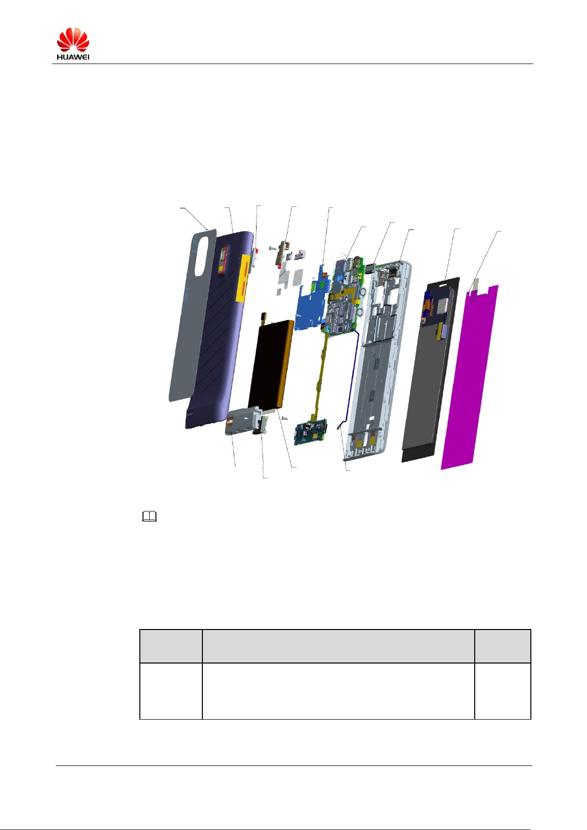
3 Exploded View
Part
Number
Description
Quantity
03021PLT
Manufactured Board, U9200-1, HD1U9200MG,
U9200-1Handset Main Board (GSM 4 Band,
W2100/W1900/W1700/W900/W850), Terminal Dedicated,
2*2
1
NOTE
Battery cover
protective film
Battery
cover
Bluetooth
antenna
GPS
antenna
Shielding
cover
PCBA
Receiver
Front cover
Touchscreenrelated
components
Touchsreen
protective
film
Antenna-related
components
Speaker
Battery
Coaxial line
3.1 Exploded View
Figure 3-1 shows the exploded view of the U9200.
Figure 3-1 Exploded view of the U9200
The components shown in the Figure 3-1 are structural parts of the phone, and cannot be used as
reference when requesting spare parts.
3.2 Component List
Table 3-1 lists the components of the U9200.
Table 3-1 Components of the U9200
U9200 Maintenance Manual
INTERNAL
(2012-06-13)
Huawei Proprietary and Confidential
Copyright © Huawei Technologies Co., Ltd.
Page 10 of 80
Part
Number
Description
Quantity
03021KAQ
Manufactured Board, U9200, HD1U9200LS, U9200 light
sensor FPC(GSM 4 band,
W2100/W1900/W1700/W850W/W900),1*1
1
03021KAH
Manufactured Board, U9200, U9200FL, U9200 flash light
FPC(GSM 4 band,
W2100/W1900/W1700/W850W/W900),1*1
1
03021KAF
Manufactured Board, U9200, HD1U9200L, U9200 main
FPC(GSM 4 band,
W2100/W1900/W1700/W850W/W900),1*1
1
03021KAP
Manufactured Board, U9200, HD1U9200SP, U9200 speaker
board(GSM 4 band,
W2100/W1900/W1700/W850W/W900),2*6
1
22020079
Speaker, 8ohm, 0.5w,11*15*3.5(Improved), Terminal
Dedicated
1
22030044
Receiver, 32ohm,6*15*2.0mm, wideband, Terminal Dedicated
1
23040221
LCD Indication Module, single display, AMOLED,
4.29'',540*RGB*960,16.7M,16:9,2.368mm (typ), with touch
panel, BTB
1
23060074
Camera Module Group, CMOS, 1.3M-FF-Front-HD-BTB
1
23060080
Camera Module Group, 1/3.2" CMOS/BSI, 8M, 3264*2448,
Terminal Dedicated
1
27160904
Terminal Antenna, 824MHz-960MHz/1710MHz-2170MHz,
larger than -3dBi, isotropic, linear polarization, smaller than 3,
4W, U9200 Main Antenna, LDS Antenna, Amphenol
1
27160905
Terminal Antenna, 1575MHz, larger than -3dBi, isotropic,
linear polarization, smaller than 2, 4W, U9200 GPS Antenna,
LDS Antenna, Amphenol
1
27160906
Terminal Antenna, 2400MHz-2500MHz, larger than -4dBi,
isotropic, smaller than 2.5,4W, U9200 WIFI Antenna, LDS
Antenna, Amphenol
1
04050383
Out Sourcing, RF Coaxing Cable, 82.5mm, fit 14240433,
Terminal Dedicated
1
NOTE
The list of components is provided for reference only. This list is subject to change without notice. The
latest component list is available on Huawei's ITEM information system. If you have any questions,
contact your local technical support center.
U9200 Maintenance Manual
INTERNAL
(2012-06-13)
Huawei Proprietary and Confidential
Copyright © Huawei Technologies Co., Ltd.
Page 11 of 80
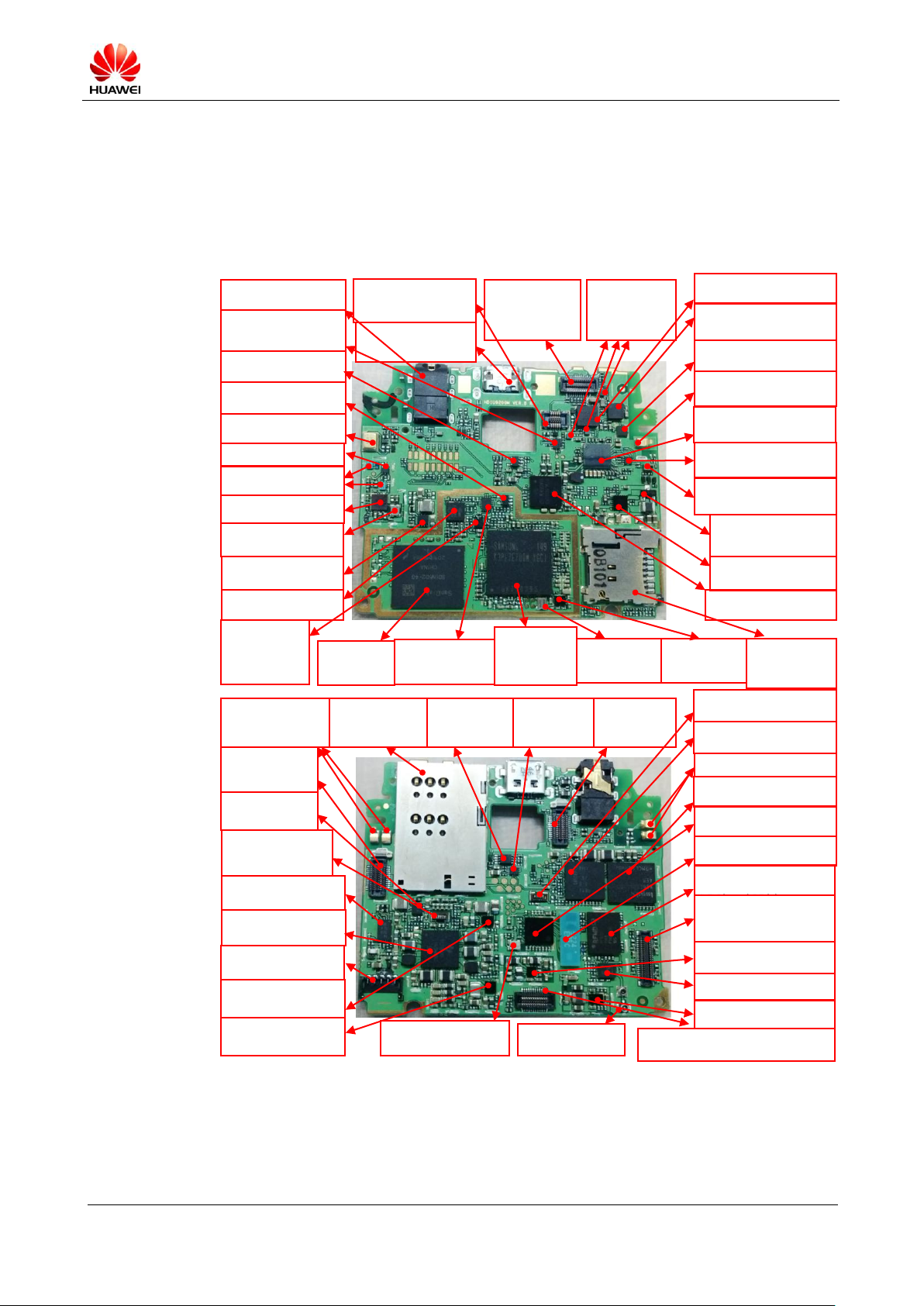
4 Layout of Components on the Main Board
U3699, GPS low noise amplifier
Failure symptom: GPS failure
U4704, RF PA
Failure symptom: call establishment
failure,
U1201, CODEC chip
Failure symptom: audio playback
failure
U4802, RF DCDC
Failure symptom: call establishment
failure
U4701, RF transceiver
Failure symptom: call establishment
failure
Z3599, Wi-Fi/Bluetooth filter
Failure symptom: Wi-Fi/Bluetooth
failure
J1602, AMOLED connector
Failure symptom: unexpected
problems of the display and
touchscreen,
Power-on failure, and software
U3101, MHL chip
Failure symptom: MHL failure
J2101, microSD card
socket
Failure symptom:
microSD card
identification failure
MIC1402, secondary MIC
Failure symptom: background
noise
J2201, FPC connector
Failure symptom:
power-on, side button, and
flashlight failure
X900, crystal (32 KHz)
Failure symptom: power-on
failure
U1901, charging chip
Failure symptom: charging failure
and power-on failure
U3201, 2.85 V DCDC
Failure symptom: power-on
failure
U4702, RF duplexer
Failure symptom: call establishment
U301/U301_POP,
AP+DDR2
Failure symptom:
power-on failure
Z3601, Z3602, GPS filter
Failure symptom: GPS failure
U3601, GPS chip
Failure symptom: GPS failure
Q1901, discharging MOS
transistor
Failure symptom: power-on
failure
J3602, J3603, antenna clip
Failure symptom: poor GPS signal
J1102, EMMC
Failure symptom:
power-on failure
U3259, DC-DC
Failure symptom: rear
camera failure
U901, power management chip
Failure symptom: power-on
failure
VCXO900, primary
crystal oscillator
Failure symptom:
power-on failure
U501, clock buffering
chip
Failure symptom:
power-on failure
J3503, J3504, antenna clip
Failure symptom: poor
Wi-Fi/Bluetooth signal
J2102, SIM card
connector
Failure symptom:
unexpected problems of
SIM card
J1800, camera
connector
Failure symptom:
rear camera failure
TCXO3601, GPS crystal
oscillator
Failure symptom: GPS failure
U3103, level shifter
chip
Failure symptom:
MHL failure
U3102, analog switch
Failure symptom: USB
and MHL failure
U3501, Wi-Fi/Bluetooth switch
Failure symptom: Wi-Fi/Bluetooth
failure
J3505, Wi-Fi/Bluetooth antenna clip
Failure symptom: Wi-Fi/Bluetooth
failure
U2005, COMPASS chip
Failure symptom: compass failure
U3401, Wi-Fi/Bluetooth/FM chip
Failure symptom: Wi-Fi/Bluetooth/FM
failure
U2004, acceleration sensor chip
Failure symptom: accelerometer
failure
U3104, 3.3 V LDO
Failure symptom: MHL failure
U3169, phase inverter
Failure symptom: MHL failure
U2401, LED control chip
Failure symptom: triple color
LED
J1500, headset jack
Failure symptom: headset failure
J1900, IO connector
Failure symptom: unexpected
problems of USB/MHL/charging
J1801, front camera
connector
Failure symptom:
unexpected problems of
front camera
J1402, FPC connector
Failure symptom: unexpected
problems of triple color LED/light
sensor
U2003, gyroscope chip
Failure symptom: gyroscope failure
U1897, U1898, U1899,
switch
Failure symptom:
unexpected camera
problems
U1301, energy meter
Failure symptom: power-on and
charging failure
J1301, battery connector
Failure symptom: power-on and
charging failure
U1800, flashlight control chip
Failure symptom: unexpected
flashlight problems
U902, DC-DC
Failure symptom: power-on
failure
U3801, MODEM chip
Failure symptom: call establishment
failure
U401, Gate
Failure symptom:
unexpected CP
problems, power-on
failure
U1900, switch
Failure symptom:
unexpected USB
problems, power-on
failure
U4801, RF DCDC
Failure symptom: call establishment
failure
U4703, RF switch
Failure symptom: call establishment
failure
J2202, primary FPC connector
Failure symptom: call establishment failure,
unexpected problems of the speaker, motor, and
U2601, MODEM MCP
Failure symptom: call establishment
failure
X2601, crystal (32 KHz)
Failure symptom: call establishment
failure
U4708, crystal oscillator (26 MHz)
Failure symptom: call
establishment failure
J4710, RF connector
Failure symptom: call
establishment failure
Figure 4-1 shows the U9200's main board components.
Figure 4-1 U9200's PCBA components
4.1 List of Components on the Main Board
Table 4-1 lists the U9200's main board components.
U9200 Maintenance Manual
INTERNAL
(2012-06-13)
Huawei Proprietary and Confidential
Copyright © Huawei Technologies Co., Ltd.
Page 12 of 80
Table 4-1 U9200's main board components
Part Number
Name
Position
19040121
Protection Tube, Fast Blowout Fuse, 24 V, 2 A, IEC
Spec, 0.03ohm, 0.100 A*A*Sec, UL, Terminal Dedicated
F1900
14240309
IO Connector, Female, 5pin, WTB Connector, SMT,
Terminal Dedicated
J1301
14240199
BTB Connector, Female, 10Pin, 0.4mm, SMT, 0.9mm,
Terminal Dedicated
J1402
14240381
Headphone Connector, 3.5mm, 6pin, Side plugging,
SMT, Mid Mount
J1500
14240375
BTB Connector, female, 40Pin, 0.4mm, 0.8mm, SMT,
Terminal Dedicated
J1602
14240181
BTB Connector, Female, 24Pin, 0.4mm, SMT, Mating
Height 1.0mm, Terminal Dedicated
J1800,
J1801,
J2201,
J2202
14240247
IO Connector, Micro_B Type Female, 5pins, Side
Plugging Type, SMT, 4 Dip, Mid Mount, 1.5mm Height
from PCB Top Side, Terminal Dedicated
J1900
14240228
Card Connecter, MicroSD Receptacle, 8pin,
PUSH-PUSH, 1.1mm, Have Lock, Without Hold Peg,
1.45mm, Terminal Dedicated
J2101
14240301
Card Socket Connector, SIM Card Socket, 6pin,
PUSH-PUSH, 1.25mm, With Lock, 1.2mm, Terminal
Dedicated
J2102
51623073
RF shielding frame
J2451
51623077
GPS shielding cover
J2452
51623074
PMU shielding frame
J2454
51623076
main shielding cover hooker
J2481,
J2482
51621274
DKBA8.382.0615, Main Antenna SMT Spring, C5600
J3503,
J3504,
J3505,
J3602,
J3603
14240433
RF Connector, Coaxial Connector, 50ohm, Straight, male,
SMT, W.FL2, Terminal Dedicated
J4710
14240432
RF Connector, RF Switch, Straight, female, SMT,
Terminal Dedicated
J4711
22050076
Microphone,-38dB.,3.76*2.95*1.1mm, silicon, bottom
MIC1402
U9200 Maintenance Manual
INTERNAL
(2012-06-13)
Huawei Proprietary and Confidential
Copyright © Huawei Technologies Co., Ltd.
Page 13 of 80
Part Number
Name
Position
15060228
MOSFET, P Channel, -12V, -2.4 A, 112mohm, -8 V,
SOT23, from 15060150,TS16949, Terminal Dedicated
Q1901
12070038
Temperature Compensated Oscillator, 26MHz,
+/-1.5ppm(max),+1.8V, +/-0.5ppm(max),
-40degC,85degC, Terminal Dedicated
TCXO3601,
VCXO900
41100049
Terminal Application Processor, S-PBGA-N547, Dual
Cortex-A9 1.5 GHz, 32KB, 1.2V, 32bit, 3000mW,
2000mW, HS version, Terminal Dedicated, Dual Core
Cortex-A9 1.5 GHz
U301
40020151
DDR2 DRAM, 8Gb LPDDR2, 400MHz,
32bit,1.8V/1.2V, 216BALL FBGA(POP), Terminal
Dedicated
U301_POP
36020320
LVCMOS, Dual 2 Input And Gate,VSSOP, 4.5ns, 24mA,
LVCOMS, LVCOMS, 0ns, 0ns, 0ns
U401
39130132
Clock Driver, 0.01MHz-52MHz,
LVCMOS/LVTTL,2.3V-5.5V-WCSP-1:4- Terminal
dedicated
U501
39070114
Power Management IC,2.5-4.8 V, seven DC-DC, eleven
LDO, FBGA187, Terminal Dedicated
U901
39110646
Power Driver, Buck DCDC, CSP16, OMAP platform
core driver, Terminal Dedicated
U902
40060351
NAND Flash, 4GB EMMC V4.41, 52 MHz, 1024 KB,
3.3 V, FBGA153 (Pb-free), Terminal Dedicated
U1102
43110064
AUDIO Chip, audio codec, OMAP Solution, PBGA120,
Terminal Dedicated
U1201
39070073
-0.3–2.75 V, Battery Gauge, SON, Terminal Dedicated
U1301
39110620
Power Driver, 1.5 A LED flash driver IC, CSP, Terminal
Dedicated
U1800
38020065
Analog Switch, one input one output load switch, 1.2
V–4.0 V, 150mohm, WLCSP
U1810,
U1897,
U1898,
U1899
38020062
Analog Switch, 2 channel USB highspeed switch,
3.0–4.3V, Ron(max)<6.5ohm, Ron(typ)<4ohm, 550MHz,
UMLP/UQFN
U1900
39070117
Battery Management IC, 4.2V, 18 V, Charger with
separate Power Path Control, WCSP, SMT, Terminal
Dedicated
U1901
38140020
Semiconductor Sensor, three-axis gyroscope, SMT
U2003
38140064
Semiconductor Sensor, Accelerometer, LGA, 3axis,
Terminal Dedicated
U2004
U9200 Maintenance Manual
INTERNAL
(2012-06-13)
Huawei Proprietary and Confidential
Copyright © Huawei Technologies Co., Ltd.
Page 14 of 80
Part Number
Name
Position
38140024
Semiconductor Sensor, E-Compass, WL-CSP (Pb-free),
3axis, Terminal Dedicated
U2005
39110463
Control Chip, LED Control Chip, QFN-RUE, Terminal
Dedicated
U2401
40060346
MCP, 1Gb(64Mx16) NAND FLASH, 200MHz, 128KB,
1.8V, 130ball BGA (Pb-free), 256Mb (16Mbx16) DDR,
Terminal Dedicated
U2601
43090124
VIDEO Chip, 49 VFBGA, 1.2V/1.8V/3.3V,
HDMI&USB 2in1, 1080p/30Hz, Terminal Dedicated
U3101
38020061
Analog Switch, DPDT, 2.7–4.3V, 1900MHz, UMLP16
U3102
36020401
CMOS,2BIT-1.8V/3.3V Level Shifter,GFN8
(Pb-free),1.5ns, 14mA, CMOS, Open drain, Terminal
Dedicated
U3103
39110548
LDO, 3.3 V, 2%,0.15 A, SC70-5, Terminal Dedicated
U3104
36020336
LVCMOS, Unbuffer Single Inverter Gate, SC-70,9.0ns,
4.0mA, CMOS, CMOS
U3169
39110566
Switching Regulators, 1–4V, 1.5A, SMT, Terminal
Dedicated
U3201,
U3259
39210010
Terminal Baseband process IC, Single Band 2.4 GHz
WLAN/Bluetooth 2.1/FM Single chip-BCM4330, 2.3–5.5
V, WLBGA133(Pb-free)
U3401
47140049
RF Switch, 0.5–3.0 GHz, SP3T, 0.45 dB, 1.22, 20 dB,
TSON, 200–260V(HBM), Terminal Dedicated
U3501
39210004
Terminal Baseband Peripheral IC, GPS Receiver,
2.3–5.5V-WLBGA42 (Pb-free), Terminal Dedicated
U3601
47090053
RF LNA, 1575 MHz, 14 dB min., 1.6 dB max., SOT886,
Terminal Dedicated
U3699
39200240
Terminal Baseband process IC, WCDMA/GSM Dual,
mode Baseband Processor-XMM6260
(PMB9811),3.05V-4.8V, PG-VF2BGA-221-1
U3801
39200241
Terminal Baseband process IC, WCDMA/GSM Dual,
Mode RF Transceiver SMartUE2 (PMB5712),2.5V/1.8V,
PG-WFWLB-138-2
U4701
47140093
RF Switch, 824–2170MHz, SP8T ASM, 1.2dB max.,
1.6max.,LGA, Terminal Dedicated
U4703
12070027
Temperature Compensated Oscillator, 26MHz,
+/-2.5ppm,1.8v-2.9v, +/-2.5ppm, 30degC, 85degC,
Terminal Dedicated
U4708
U9200 Maintenance Manual
INTERNAL
(2012-06-13)
Huawei Proprietary and Confidential
Copyright © Huawei Technologies Co., Ltd.
Page 15 of 80
Part Number
Name
Position
39070119
Power Management IC, 2.9–5.1V, PUMP-BUCK DCDC
0-5V, auxiliary charge pump 4 V 10 mA, WLCSP,
Terminal Dedicated
U4801
39070116
Power Management IC, 2.9–5.1V, 3bucks(1.2V 3A; 1.8V
3A; 2.85V 3A),1 LDO 2.65V, compatible with infineon
transceiver PMB5712, 16-BUMP WLCSP, Terminal
Dedicated
U4802
12020125
Crystal, 0.032768 MHz, 12.5pF+/-30ppm, 60/80kohm,
3.2*1.5 SMD, Terminal Dedicate, ELOM, TS16949
X2601,
X900
13030052
Ceramic Filter, 2450 MHz, 1.8 dB,20125, Terminal
Dedicated
Z3599
13010180
SAW filter, 1575.42 MHz,0.9dB,1.4*1.1 mm, for
terminal using only
Z3601,
Z3602
51633362
U8650_WIFI_CHIP_GASKET, U8650
U3401
13080147
Duplexer,
RX:1805-1880MHz/TX:1920-1980MHz/RX:2110-2170
MHz/TX:1710-1755MHz/RX:2110-2155MHz/TX:18501910MHz/RX:1930-1990MHz/TX:824-849MHz/869-894
MHz/TX:880-915MHz/RX:925-960MHz,
3dB.,3.95dB.,47dB, SMT, Terminal Dedicated
U4702
47100455
RF Power Amplifying Module,
1710–1785MHz/1850–1910MHz/1920–1980MHz/824–8
49MHz/880–915MHz, 35.7dB max., 35dBm, MCM,
Terminal Dedicated
U4704
NOTE
The list of components is provided for reference only. This list is subject to change without notice. The
latest component list is available on Huawei's ITEM information system. If you have any questions,
contact your local technical support center.
U9200 Maintenance Manual
INTERNAL
(2012-06-13)
Huawei Proprietary and Confidential
Copyright © Huawei Technologies Co., Ltd.
Page 16 of 80
5 Software Upgrade
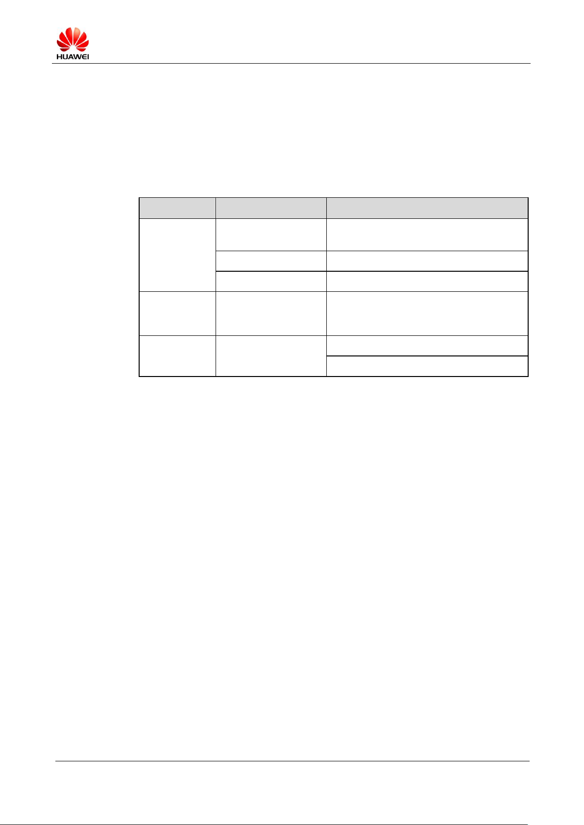
Category
Item
Description
Upgrade
environment
Computer
Operating system: Windows 2000, Windows
XP or Windows 7
microSD card
With at least 512 MB free space
Battery
With at least 20% power remaining
Upgrade file
update.app
This version is provided for reference only.
Please download the latest version when
upgrading the software.
microSD card upgrade
Normal upgrade
Forcible upgrade
5.1 Upgrade Preparation
Table 5-1 lists the items to be prepared before a software upgrade.
Table 5-1 Items to be prepared before a software upgrade
5.2 microSD Card Upgrade
5.2.1 Normal Upgrade
1. Create a folder named dload in the root directory of the microSD card.
2. Copy the upgrade file update.app to the dload folder.
3. Install the microSD card on the phone and power the phone on.
4. Enter *#*#2846579#*#* in dialing mode. Choose ProjectMenu > Upgrade > SD card
upgrade, and click Confirm.
The upgrade progress is displayed on the LCD.
After the upgrade is completed, the phone automatically restarts.
If the upgrade fails, the phone stays on the upgrade page, and an upgrade failure message is
displayed.
5.2.2 Forcible Upgrade
If the phone fails to be powered on, perform the following operations to start a forcible
upgrade:
1. Create a folder named dload in the root directory of the microSD card.
2. Copy the upgrade file update.app to the dload folder.
3. Install the microSD card on the phone.
U9200 Maintenance Manual
INTERNAL
(2012-06-13)
Huawei Proprietary and Confidential
Copyright © Huawei Technologies Co., Ltd.
Page 17 of 80
4. In power-off state, press the volume up, volume down, and power keys concurrently for
Failure
Solution
microSD card upgrade
failure
1. Check whether the upgrade file is correct.
2. Check whether the upgrade file storage directory is correct.
3. Check whether the upgrade method is correct.
4. Check whether the microSD card functions properly.
5. Perform the upgrade again.
more than 3 seconds.
The phone enters the upgrade state automatically. The upgrade progress is displayed on the
LCD.
After the upgrade is completed, the phone automatically restarts.
If the upgrade fails, the phone stays on the upgrade page, and an upgrade failure message is
displayed.
5.3 Troubleshooting
Table 5-2 describes the troubleshooting process.
Table 5-2 Troubleshooting process
U9200 Maintenance Manual
INTERNAL
(2012-06-13)
Huawei Proprietary and Confidential
Copyright © Huawei Technologies Co., Ltd.
Page 18 of 80
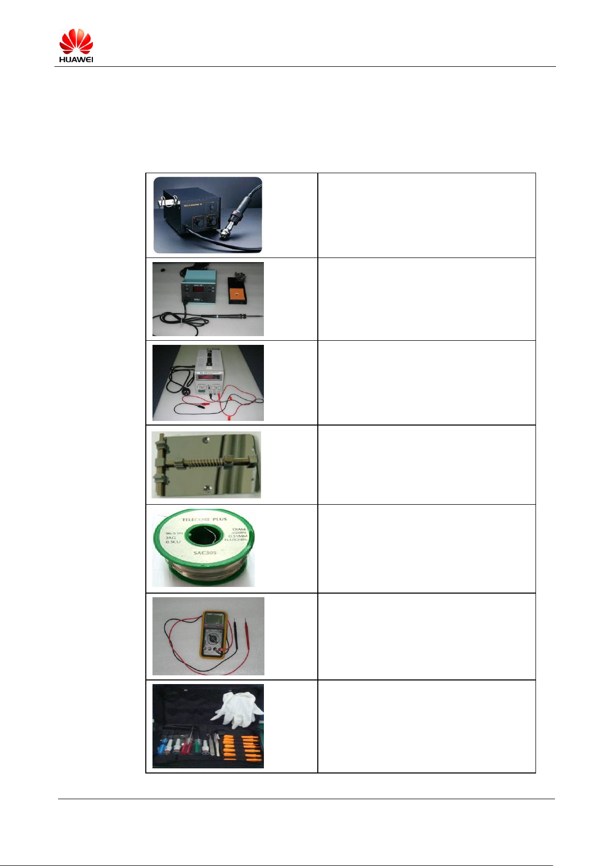
6 Maintenance Tools
Name: constant-temperature heat gun
Usage: to heat components
Name: soldering iron
Usage: to solder components
Name: DC power supply
Usage: to supply DC power
Name: soldering table
Usage: to secure the PCBA
Name: lead-free solder wire
Usage: soldering
Name: digital multimeter
Usage: to measure during repair
Name: toolkit
Usage: to assemble and disassemble terminal
products
Table 6-1 lists the maintenance tools.
Table 6-1 Maintenance tools

U9200 Maintenance Manual
INTERNAL
(2012-06-13)
Huawei Proprietary and Confidential
Copyright © Huawei Technologies Co., Ltd.
Page 19 of 80
Name: electric screwdriver
Usage: to fasten and remove screws
U9200 Maintenance Manual
INTERNAL
(2012-06-13)
Huawei Proprietary and Confidential
Copyright © Huawei Technologies Co., Ltd.
Page 20 of 80
7 Disassembly Procedure
7.1 Disassembly Procedure
1. Remove the microSD card slot holder, and remove the Philips screws (the screws are
covered by a white anti-dismantle label).
Figure 7-1 microSD card slot holder
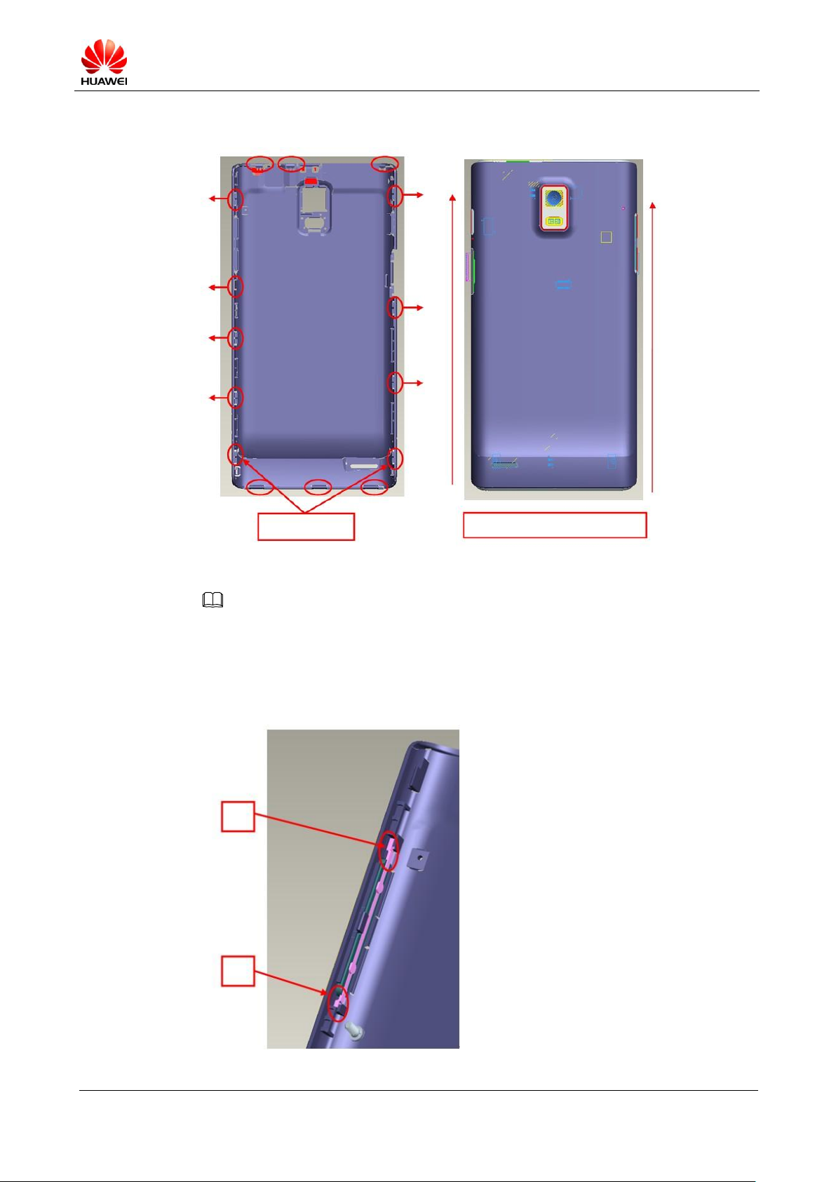
2. Remove the battery cover.
(1) Stick a crowbar into the gaps at the bottom corners respectively, and pry outwards
to remove the two buckles.
(2) Remove the three bottom female buckles.
(3) Remove the top three buckles.
U9200 Maintenance Manual
INTERNAL
(2012-06-13)
Huawei Proprietary and Confidential
Copyright © Huawei Technologies Co., Ltd.
Page 21 of 80
Figure 7-2 Removing the battery cover
NOTE
Stick the crowbar into
the two gaps first
Move the rear cover upwards to
open the side buckles
Higher
flexibility
Lower
flexibility
When you reinstall the volume keys, pay attention to the direction where the volume key should be
placed. Place the key of a higher flexibility at the upper position. After the two keys are installed, check
whether they are installed at the correct position without interference with other components around
them.
Figure 7-3 Reinstalling the volume keys

U9200 Maintenance Manual
INTERNAL
(2012-06-13)
Huawei Proprietary and Confidential
Copyright © Huawei Technologies Co., Ltd.
Page 22 of 80
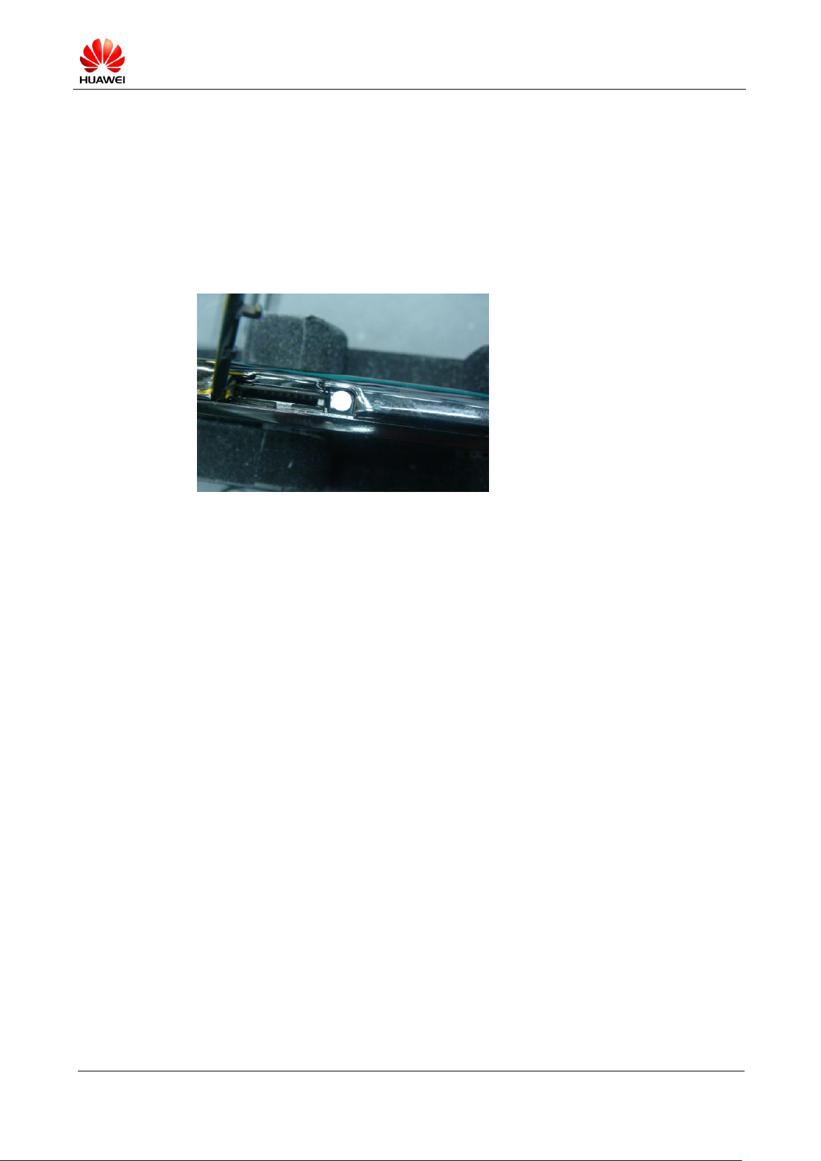
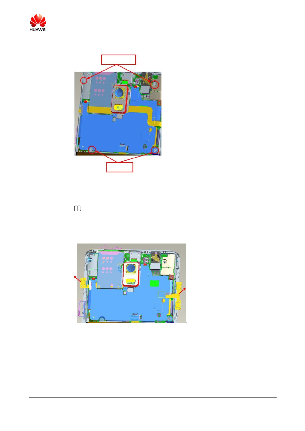
3. Remove the main antenna and sub board.
Coaxial-line switch
BTB connector
(1) Remove the two Philips screws, and take out the main antenna support.
Figure 7-4 Removing the two Philips screws
(2) Hold the housing and sub board with your left hand, and remove the coaxial-line
switch using tweezers with your right hand.
Stick a crowbar into the spacing, as shown in the following figure, to pry upwards
to remove the sub board. Disconnect the BTB connector.
Figure 7-5 Removing the sub board
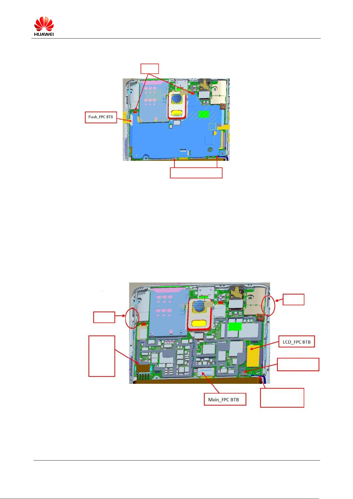
4. Remove the main shielding cover and Flash_FPC.
(1) Remove the four screws.
U9200 Maintenance Manual
INTERNAL
(2012-06-13)
Huawei Proprietary and Confidential
Copyright © Huawei Technologies Co., Ltd.
Page 23 of 80
Figure 7-6 Removing the four screws
NOTE
Hexagon screws
Plus screws
(2) Lift the volume key FPC and power key FPC to the extent that they are separated
from the magnesium alloy.
When you reinstall the FPCs, check whether the adhesive backed is damaged; if it is, change the
adhesive, and remove the residues from the magnesium alloy.
Figure 7-7 Lifting the volume key FPC and power key FPC
(3) Remove the shielding cover.
(4) Disconnect the BTB connector from the Flash_FPC using tweezers, and remove the
Stick tweezers into the spacing, as shown in the following figure, to pry upwards.
Take care not to damage the connector under the shielding cover or deform the
shielding cover. Remove the shielding cover from the two buckles.
FPC.
U9200 Maintenance Manual
INTERNAL
(2012-06-13)
Huawei Proprietary and Confidential
Copyright © Huawei Technologies Co., Ltd.
Page 24 of 80
Figure 7-8 Removing the shielding cover
Stick tweezers into the
spacing.
Buckles
Buckle
Put your nail
in the groove
and move
upwards to
open the
battery
connector.
Coaxial-line switch
Stick tweezers into the
bottom right corner of
the main board.
Buckle
5. Remove the main board.
(1) Disconnect the BTS connector between the LCD_FPC and Main_FPC.
(2) Turn off the coaxial-line switch using tweezers.
(3) Put your nail in the groove and move upwards to open the battery connector.
(4) Stick tweezers into the bottom right corner of the main board, and pry upwards.
Apply a proper force to avoid damage to the two buckles on the left and right.
Figure 7-9 Removing the main board
 Loading...