

SUN2000-(50KTL-ZHM3, 50KTL-M3)
User Manual
Issue 03
Date 2022-08-30
HUAWEI TECHNOLOGIES CO., LTD.

Copyright © Huawei Technologies Co., Ltd. 2022. All rights reserved.
No part of this document may be reproduced or transmitted in any form or by any means without prior
written consent of Huawei Technologies Co., Ltd.
Trademarks and Permissions
and other Huawei trademarks are trademarks of Huawei Technologies Co., Ltd.
All other trademarks and trade names mentioned in this document are the property of their respective
holders.
Notice
The purchased products, services and features are stipulated by the contract made between Huawei and
the customer. All or part of the products, services and features described in this document may not be
within the purchase scope or the usage scope. Unless otherwise specied in the contract, all statements,
information, and recommendations in this document are provided "AS IS" without warranties, guarantees
or representations of any kind, either express or implied.
The information in this document is subject to change without notice. Every eort has been made in the
preparation of this document to ensure accuracy of the contents, but all statements, information, and
recommendations in this document do not constitute a warranty of any kind, express or implied.
Huawei Technologies Co., Ltd.
Address: Huawei Industrial Base
Bantian, Longgang
Shenzhen 518129
People's Republic of China
Website: https://e.huawei.com
Issue 03 (2022-08-30) Copyright © Huawei Technologies Co., Ltd. i
SUN2000-(50KTL-ZHM3, 50KTL-M3)
User Manual About This Document
About This Document
Overview
This document describes the SUN2000-50KTL-ZHM3 and SUN2000-50KTL-M3
(also referred to as SUN2000) in terms of their installation, electrical connections,
commissioning, maintenance, and troubleshooting. Before installing and operating
the SUN2000, ensure that you are familiar with the features, functions, and safety
precautions provided in this document.
Intended Audience
This document is applicable to:
● Installers
● Users
Symbol Conventions
The symbols that may be found in this document are
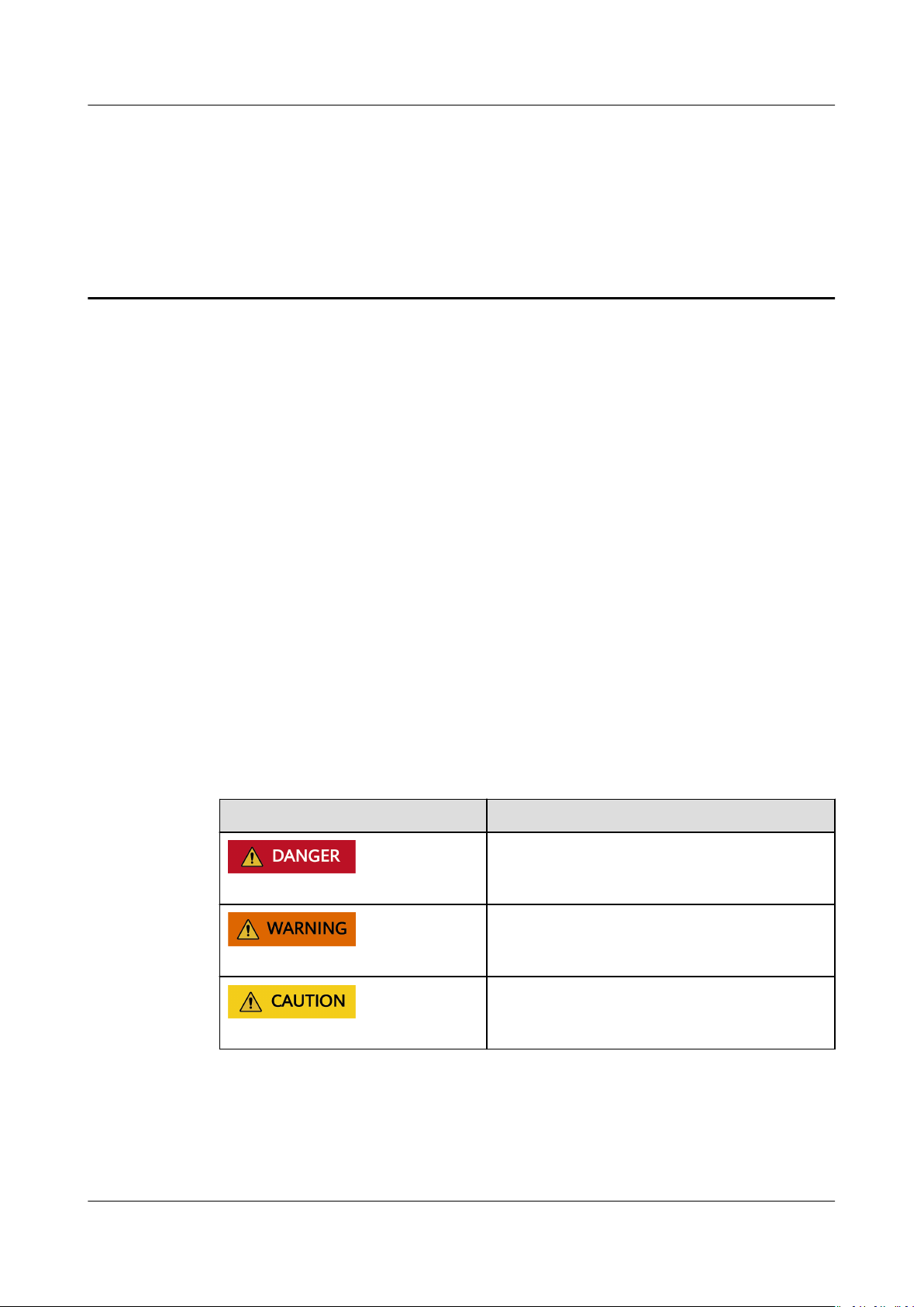
Symbol
dened as follows.
Description
Indicates a hazard with a high level of risk
which, if not avoided, will result in death or
serious injury.
Indicates a hazard with a medium level of
risk which, if not avoided, could result in
death or serious injury.
Indicates a hazard with a low level of risk
which, if not avoided, could result in minor
or moderate injury.
Issue 03 (2022-08-30) Copyright © Huawei Technologies Co., Ltd. ii

SUN2000-(50KTL-ZHM3, 50KTL-M3)
User Manual About This Document
Symbol Description
Indicates a potentially hazardous situation
which, if not avoided, could result in
equipment damage, data loss, performance
deterioration, or unanticipated results.
NOTICE is used to address practices not
related to personal injury.
Supplements the important information in
the main text.
NOTE is used to address information not
related to personal injury, equipment
damage, and environment deterioration.
Change History
Changes between document issues are cumulative. The latest document issue
contains all changes made in earlier issues.
Issue 03 (2022-08-30)
Added the SUN2000-50KTL-M3 model.
Updated 2.1 Product Introduction.
Updated 10 Technical
Updated A Grid Codes.
Added G Rapid Shutdown.
Added H NS Protection.
Issue 02 (2022-08-12)
Updated 5.2 Preparing Cables.
Updated 5.4 Connecting the AC Output Power Cable.
Updated 5.5 Installing the DC Input Power Cable.
Specications.
Updated 10 Technical
Specications.
Issue 01 (2022-05-20)
This issue is the rst ocial release.
Issue 03 (2022-08-30) Copyright © Huawei Technologies Co., Ltd. iii

SUN2000-(50KTL-ZHM3, 50KTL-M3)
User Manual Contents
Contents
About This Document................................................................................................................ ii
1 Safety Information.................................................................................................................. 1
1.1 General Safety.......................................................................................................................................................................... 1
1.2 Personnel Requirements....................................................................................................................................................... 2
1.3 Electrical Safety........................................................................................................................................................................3
1.4 Installation Environment Requirements.......................................................................................................................... 4
1.5 Mechanical Safety................................................................................................................................................................... 4
1.6 Commissioning......................................................................................................................................................................... 6
1.7 Maintenance and Replacement..........................................................................................................................................6
2 Overview....................................................................................................................................7
2.1 Product Introduction.............................................................................................................................................................. 7
2.2 Appearance................................................................................................................................................................................9
2.3 Label Description.................................................................................................................................................................. 10
2.4 Working Principles................................................................................................................................................................ 12
2.4.1 Circuit Diagram.................................................................................................................................................................. 12
2.4.2 Working Modes.................................................................................................................................................................. 12
3 SUN2000 Storage...................................................................................................................14
4 Installation..............................................................................................................................15
4.1 Checking Before Installation............................................................................................................................................. 15
4.2 Tool Preparation.................................................................................................................................................................... 16
4.3 Selecting an Installation Position.................................................................................................................................... 17
4.4 Moving the SUN2000.......................................................................................................................................................... 21
4.5 Installing the Mounting Bracket...................................................................................................................................... 22
4.5.1 Support-mounted Installation.......................................................................................................................................23
4.5.2 Wall-mounted Installation............................................................................................................................................. 24
4.6 Installing a SUN2000........................................................................................................................................................... 25
5 Electrical Connections.......................................................................................................... 27
5.1 Precautions.............................................................................................................................................................................. 27
5.2 Preparing Cables................................................................................................................................................................... 28
5.3 Connecting the PE Cable.................................................................................................................................................... 30
5.4 Connecting the AC Output Power Cable...................................................................................................................... 32
Issue 03 (2022-08-30) Copyright © Huawei Technologies Co., Ltd. iv

SUN2000-(50KTL-ZHM3, 50KTL-M3)
User Manual Contents
5.5 Installing the DC Input Power Cable.............................................................................................................................. 37
5.6 (Optional) Installing the Smart Dongle........................................................................................................................ 40
5.7 Connecting the Signal Cable............................................................................................................................................. 42
5.7.1 Communication Modes................................................................................................................................................... 44
5.7.2 (Optional) Connecting the RS485 Communications Cable to the SUN2000............................................... 46
5.7.3 (Optional) Connecting the RS485 Communications Cable to the Power Meter.........................................47
5.7.4 (Optional) Connecting the Power Grid Scheduling Signal Cable..................................................................... 48
6 Commissioning.......................................................................................................................50
6.1 Checking Before Power-On................................................................................................................................................50
6.2 System Power-On................................................................................................................................................................. 51
7 Man-Machine Interaction....................................................................................................53
7.1 Scenario in Which SUN2000s Are Connected to the FusionSolar Smart PV Management System.........54
7.1.1 (Optional) Registering an Installer Account............................................................................................................ 54
7.1.2 Creating a PV Plant and a User.................................................................................................................................... 55
7.1.3 SmartLogger Networking Scenario............................................................................................................................. 55
7.2 Scenario in Which SUN2000s Are Connected to Other Management Systems..............................................56
7.3 Energy Control....................................................................................................................................................................... 56
7.3.1 Grid-tied Point Control.................................................................................................................................................... 56
7.3.2 Apparent Power Control on the Inverter Output Side..........................................................................................60
8 Maintenance...........................................................................................................................62
8.1 System Power-O.................................................................................................................................................................62
8.2 Routine Maintenance.......................................................................................................................................................... 63
8.3 Troubleshooting.....................................................................................................................................................................64
8.4 Replacing a Fan..................................................................................................................................................................... 74
9 Handling the Inverter...........................................................................................................77
9.1 Removing the SUN2000..................................................................................................................................................... 77
9.2 Packing the SUN2000..........................................................................................................................................................77
9.3 Disposing of the SUN2000................................................................................................................................................ 77
10 Technical
Specications.....................................................................................................78
A Grid Codes...............................................................................................................................85
B Device Commissioning......................................................................................................... 90
C Built-in PID Recovery............................................................................................................93
D Resetting Password.............................................................................................................. 94
E Setting Dry Contact Scheduling Parameters.................................................................. 95
F AFCI...........................................................................................................................................96
G Rapid Shutdown....................................................................................................................98
H NS Protection.........................................................................................................................99
Issue 03 (2022-08-30) Copyright © Huawei Technologies Co., Ltd. v

SUN2000-(50KTL-ZHM3, 50KTL-M3)
User Manual Contents
I Smart I-V Curve Diagnosis................................................................................................. 100
J Contact Information............................................................................................................101
K Acronyms and Abbreviations........................................................................................... 103
Issue 03 (2022-08-30) Copyright © Huawei Technologies Co., Ltd. vi

SUN2000-(50KTL-ZHM3, 50KTL-M3)
User Manual 1 Safety Information
1 Safety Information
1.1 General Safety
Statement
Before installing, operating, and maintaining the equipment, read this document
and observe all the safety instructions on the equipment and in this document.
The "NOTICE", "CAUTION", "WARNING", and "DANGER" statements in this
document do not cover all the safety instructions. They are only supplements to
the safety instructions. Huawei will not be liable for any consequence caused by
the violation of general safety requirements or design, production, and usage
safety standards.
Ensure that the equipment is used in environments that meet its design
specications. Otherwise, the equipment may become faulty, and the resulting
equipment malfunction, component damage, personal injuries, or property
damage are not covered under the warranty.
Follow local laws and regulations when installing, operating, or maintaining the
equipment. The safety instructions in this document are only supplements to local
laws and regulations.
Huawei will not be liable for any consequences of the following circumstances:
● Operation beyond the conditions
● Installation or use in environments which are not
international or national standards
● Unauthorized modications to the product or software code or removal of the
product
● Failure to follow the operation instructions and safety precautions on the
product and in this document
● Equipment damage due to force majeure, such as earthquakes, re, and
storms
● Damage caused during transportation by the customer
● Storage conditions that do not meet the requirements specied in this
document
specied in this document
specied in relevant
Issue 03 (2022-08-30) Copyright © Huawei Technologies Co., Ltd. 1

D ANGER
SUN2000-(50KTL-ZHM3, 50KTL-M3)
User Manual 1 Safety Information
General Requirements
Do not work with power on during installation.
● Do not install, use, or operate outdoor equipment and cables (including but
not limited to moving equipment, operating equipment and cables, inserting
connectors to or removing connectors from signal ports connected to outdoor
facilities, working at heights, and performing outdoor installation) in harsh
weather conditions such as lightning, rain, snow, and level 6 or stronger wind.
● After installing the equipment, remove idle packing materials such as cartons,
foam, plastics, and cable ties from the equipment area.
● In the case of a
and turn on the re alarm bell or make an emergency call. Do not enter the
building on re in any case.
● Do not scrawl, damage, or block any warning label on the equipment.
● Tighten the screws to the specied torque using tools when installing the
equipment.
● Understand the components and functioning of a grid-tied PV power system
and relevant local standards.
● Repaint any paint scratches caused during equipment transportation or
installation in a timely manner. Equipment with scratches cannot be exposed
to an outdoor environment for a long period of time.
● Do not open the host panel of the equipment.
● You shall not reverse engineer, decompile, disassemble, adapt, add code to
the device software or alter the device software in any other way, research the
internal implementation of the device, obtain the device software source
code, infringe on Huawei's intellectual property, or disclose any device
software performance test results.
re, immediately leave the building or the equipment area,
Personal Safety
● If there is a probability of personal injury or equipment damage during
operations on the equipment, immediately stop the operations, report the
case to the supervisor, and take feasible protective measures.
● Use tools correctly to avoid hurting people or damaging the equipment.
● Do not touch the energized equipment, as the enclosure is hot.
1.2 Personnel Requirements
● Personnel who plan to install or maintain Huawei equipment must receive
thorough training, understand all necessary safety precautions, and be able to
correctly perform all operations.
● Only
● Only qualied professionals are allowed to remove safety facilities and inspect
Issue 03 (2022-08-30) Copyright © Huawei Technologies Co., Ltd. 2
qualied professionals or trained personnel are allowed to install,
operate, and maintain the equipment.
the equipment.

NO TE
D ANGER
SUN2000-(50KTL-ZHM3, 50KTL-M3)
User Manual 1 Safety Information
● Personnel who will operate the equipment, including operators, trained
personnel, and professionals, should possess the local national required
qualications in special operations such as high-voltage operations, working
at heights, and operations of special equipment.
● Only professionals or authorized personnel are allowed to replace the
equipment or components (including software).
● Professionals: personnel who are trained or experienced in equipment operations
and are clear of the sources and degree of various potential hazards in equipment
installation, operation, and maintenance
● Trained personnel: personnel who are technically trained, have required experience,
are aware of possible hazards on themselves in certain operations, and are able to
take protective measures to minimize the hazards on themselves and other people
● Operators: operation personnel who may come in contact with the equipment,
except trained personnel and professionals
1.3 Electrical Safety
Grounding
● For the equipment that needs to be grounded, install the ground cable
when installing the equipment and remove the ground cable last when
removing the equipment.
● Do not damage the ground conductor.
● Do not operate the equipment in the absence of a properly installed ground
conductor.
● Ensure that the equipment is connected permanently to the protective
ground. Before operating the equipment, check its electrical connection to
ensure that it is securely grounded.
General Requirements
Before connecting cables, ensure that the equipment is intact. Otherwise, electric
shocks or
● Ensure that all electrical connections comply with local electrical standards.
● Obtain approval from the local electric utility company before using the
equipment in grid-tied mode.
● Ensure that the cables you prepared meet local regulations.
● Use dedicated insulated tools when performing high-voltage operations.
rst
re may occur.
Issue 03 (2022-08-30) Copyright © Huawei Technologies Co., Ltd. 3

D ANGER
SUN2000-(50KTL-ZHM3, 50KTL-M3)
User Manual 1 Safety Information
AC and DC Power
Do not connect or disconnect power cables with power on. Transient contact
between the core of the power cable and the conductor will generate electric arcs
or sparks, which may cause
● Before making electrical connections, switch o the disconnector on the
upstream device to cut o the power supply if people may contact energized
components.
● Before connecting a power cable, check that the label on the power cable is
correct.
● If the equipment has multiple inputs, disconnect all the inputs before
operating the equipment.
re or personal injury.
Cabling
● When routing cables, ensure that a distance of at least 30 mm exists between
the cables and heat-generating components or areas. This prevents damage
to the insulation layer of the cables.
● Bind cables of the same type together. When routing cables of
ensure that they are at least 30 mm away from each other.
● Ensure that the cables used in a grid-tied PV power system are properly
connected and insulated and meet
specications.
1.4 Installation Environment Requirements
● Ensure that the equipment is installed in a well ventilated environment.
● To prevent re due to high temperature, ensure that the ventilation vents or
heat dissipation system are not blocked when the equipment is running.
● Do not expose the equipment to
not perform any operation on the equipment in such environments.
ammable or explosive gas or smoke. Do
1.5 Mechanical Safety
Using Ladders
dierent types,
● Use wooden or berglass ladders when you need to perform live working at
heights.
● When a step ladder is used, ensure that the pull ropes are secured and the
ladder is held rm.
● Before using a ladder, check that it is intact and conrm its load bearing
capacity. Do not overload it.
● Ensure that the wider end of the ladder is at the bottom, or protective
measures have been taken at the bottom to prevent the ladder from sliding.
Issue 03 (2022-08-30) Copyright © Huawei Technologies Co., Ltd. 4

SUN2000-(50KTL-ZHM3, 50KTL-M3)
User Manual 1 Safety Information
● Ensure that the ladder is securely positioned. The recommended angle for a
ladder against the oor is 75 degrees, as shown in the following gure. An
angle rule can be used to measure the angle.
● When climbing a ladder, take the following precautions to reduce risks and
ensure safety:
– Keep your body steady.
– Do not climb higher than the fourth rung of the ladder from the top.
– Ensure that your body's center of gravity does not shift outside the legs
of the ladder.
Drilling Holes
When drilling holes into a wall or
● Wear goggles and protective gloves when drilling holes.
● When drilling holes, protect the equipment from shavings. After drilling, clean
up any shavings that have accumulated inside or outside the equipment.
Moving Heavy Objects
● Be cautious to avoid injury when moving heavy objects.
oor, observe the following safety precautions:
● When moving the equipment by hand, wear protective gloves to prevent
injuries.
Issue 03 (2022-08-30) Copyright © Huawei Technologies Co., Ltd. 5

D ANGER
SUN2000-(50KTL-ZHM3, 50KTL-M3)
User Manual 1 Safety Information
1.6 Commissioning
When the equipment is powered on for the rst time, ensure that professional
personnel set parameters correctly. Incorrect settings may result in inconsistency
with local certication and aect the normal operation of the equipment.
1.7 Maintenance and Replacement
High voltage generated by the equipment during operation may cause an electric
shock, which could result in death, serious injury, or serious property damage.
Prior to maintenance, power o the equipment and strictly comply with the safety
precautions in this document and relevant documents.
● Maintain the equipment with sucient knowledge of this document and
using proper tools and testing equipment.
● Before maintaining the equipment, power it
the delayed discharge label to ensure that the equipment is powered o.
● Turn o the AC and DC switches of the SUN2000 when maintaining the
electric equipment or power distribution equipment connected the SUN2000.
● Place temporary warning signs or erect fences to prevent unauthorized access
to the maintenance site.
● If the equipment is faulty, contact your dealer.
● The equipment can be powered on only after all faults are
do so may escalate faults or damage the equipment.
o and follow the instructions on
rectied. Failing to
Issue 03 (2022-08-30) Copyright © Huawei Technologies Co., Ltd. 6

SUN2000-(50KTL-ZHM3, 50KTL-M3)
User Manual 2 Overview
2 Overview
2.1 Product Introduction
Function
Model
The SUN2000 inverter is a three-phase grid-tied PV string inverter that converts
the DC power generated by PV strings into AC power and feeds the power into the
power grid.
This document covers the following SUN2000 models:
● SUN2000-50KTL-ZHM3
● SUN2000-50KTL-M3
Figure 2-1 Model description
Table 2-1 Model description
ID
1 Series name SUN2000: three-phase grid-tied PV string
2 Power class 50K: rated power of 50 kW
3 Topology TL: transformerless
4 Region ZH: China
Issue 03 (2022-08-30) Copyright © Huawei Technologies Co., Ltd. 7
Meaning Value
inverter

SUN2000-(50KTL-ZHM3, 50KTL-M3)
User Manual 2 Overview
ID Meaning Value
5 Product code M3: product series with an input voltage level
of 1100 V DC
Networking Application
The SUN2000 applies to the grid-tied systems of industrial and commercial
rooftops and small ground PV plants. Typically, a grid-tied system consists of PV
strings, grid-tied inverters, AC switches, and power distribution units.
Figure 2-2 Networking application - single inverter scenario
(1) PV string (2) SUN2000 (3) AC power distribution
(4) Isolation transformer (5) Power grid
Supported Power Grid Types
The SUN2000 supports TN-S, TN-C, TN-C-S, TT, and IT power grids.
Figure 2-3 Power grid types
unit
Issue 03 (2022-08-30) Copyright © Huawei Technologies Co., Ltd. 8
SUN2000-(50KTL-ZHM3, 50KTL-M3)
User Manual 2 Overview
2.2 Appearance
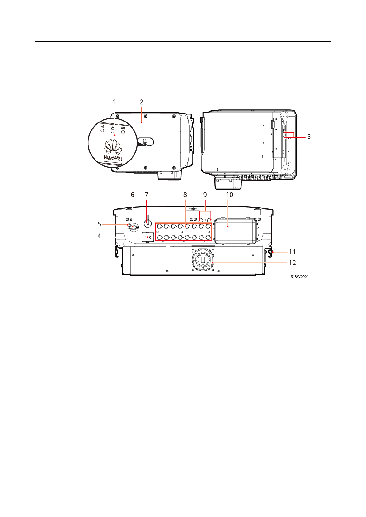
Figure 2-4 Appearance
(1) LED indicator (2) Front panel
(3) Screws for xing the awning (4) Communications port (COM)
(5) Hole for the DC switch locking
screw
(7) Smart Dongle port (4G/WLAN-FE) (8) DC input terminals (PV1–PV8)
(9) Ventilation valve (10) AC output port
(11) Ground point (12) Fan
(6) DC switch (DC SWITCH)
Issue 03 (2022-08-30) Copyright © Huawei Technologies Co., Ltd. 9
SUN2000-(50KTL-ZHM3, 50KTL-M3)
User Manual 2 Overview
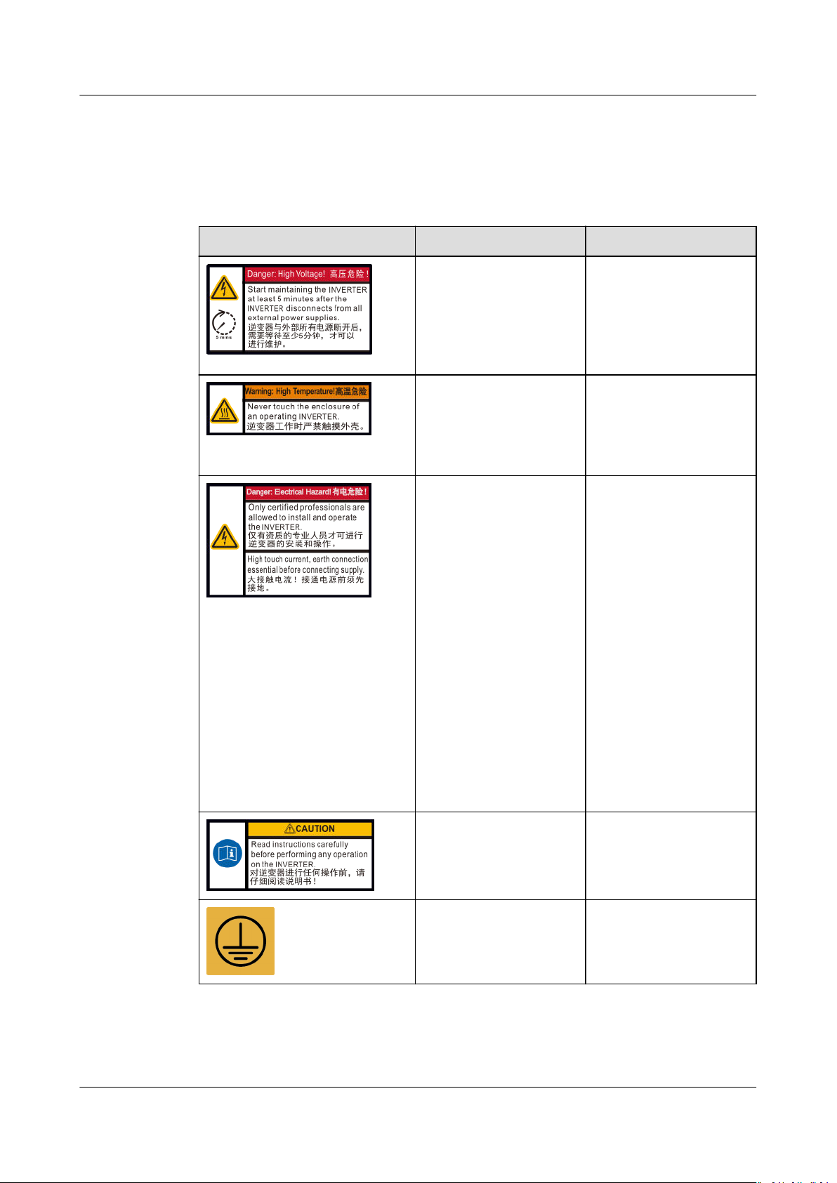
2.3 Label Description
Enclosure Labels
Symbol Name Description
Delay discharge Residual voltage exists
after the SUN2000 is
powered o. It takes 5
minutes for the
SUN2000 to discharge
to the safe voltage.
Burn warning Do not touch a
running SUN2000
because it generates
high temperatures on
the shell.
Electric shock warning ● High voltage exists
after the SUN2000
is powered on. Only
qualied and
trained electrical
technicians are
allowed to perform
operations on the
SUN2000.
● High touch current
exists after the
SUN2000 is
powered on. Before
powering on the
SUN2000, ensure
that the SUN2000
is properly
grounded.
Refer to
documentation
Reminds operators to
refer to the documents
delivered with the
SUN2000.
Grounding label Indicates the position
for connecting the PE
cable.
Issue 03 (2022-08-30) Copyright © Huawei Technologies Co., Ltd. 10

SUN2000-(50KTL-ZHM3, 50KTL-M3)
User Manual 2 Overview
Symbol Name Description
Operation warning Do not remove the DC
input connector or AC
output connector with
power on.
Weight label The SUN2000 is heavy
and needs to be
carried by three
persons.
Burn warning on
inverter handles
Do not touch the
handles within 10
minutes after the
inverter is shut down.
Indicator Indicates the SUN2000
operating information.
SUN2000 serial
number
SUN2000 WiFi login
QR code
Indicates the serial
number.
Scan the QR code to
connect to the Huawei
SUN2000 WiFi
network.
Issue 03 (2022-08-30) Copyright © Huawei Technologies Co., Ltd. 11
SUN2000-(50KTL-ZHM3, 50KTL-M3)
User Manual 2 Overview
2.4 Working Principles
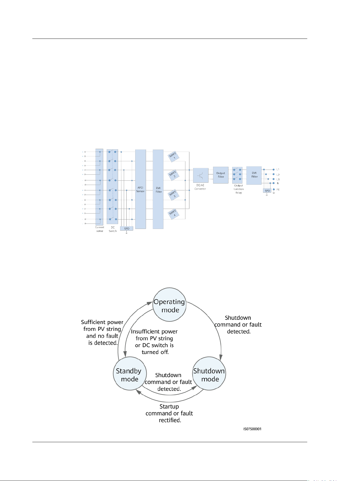
2.4.1 Circuit Diagram
A SUN2000 can connect to a maximum of eight PV strings and has four MPPT
circuits inside. Each MPPT circuit tracks the maximum power point of two PV
strings. The SUN2000 converts DC power into single-phase AC power through an
inverter circuit. Surge protection is supported on both the DC and AC sides.
Figure 2-5 Schematic diagram
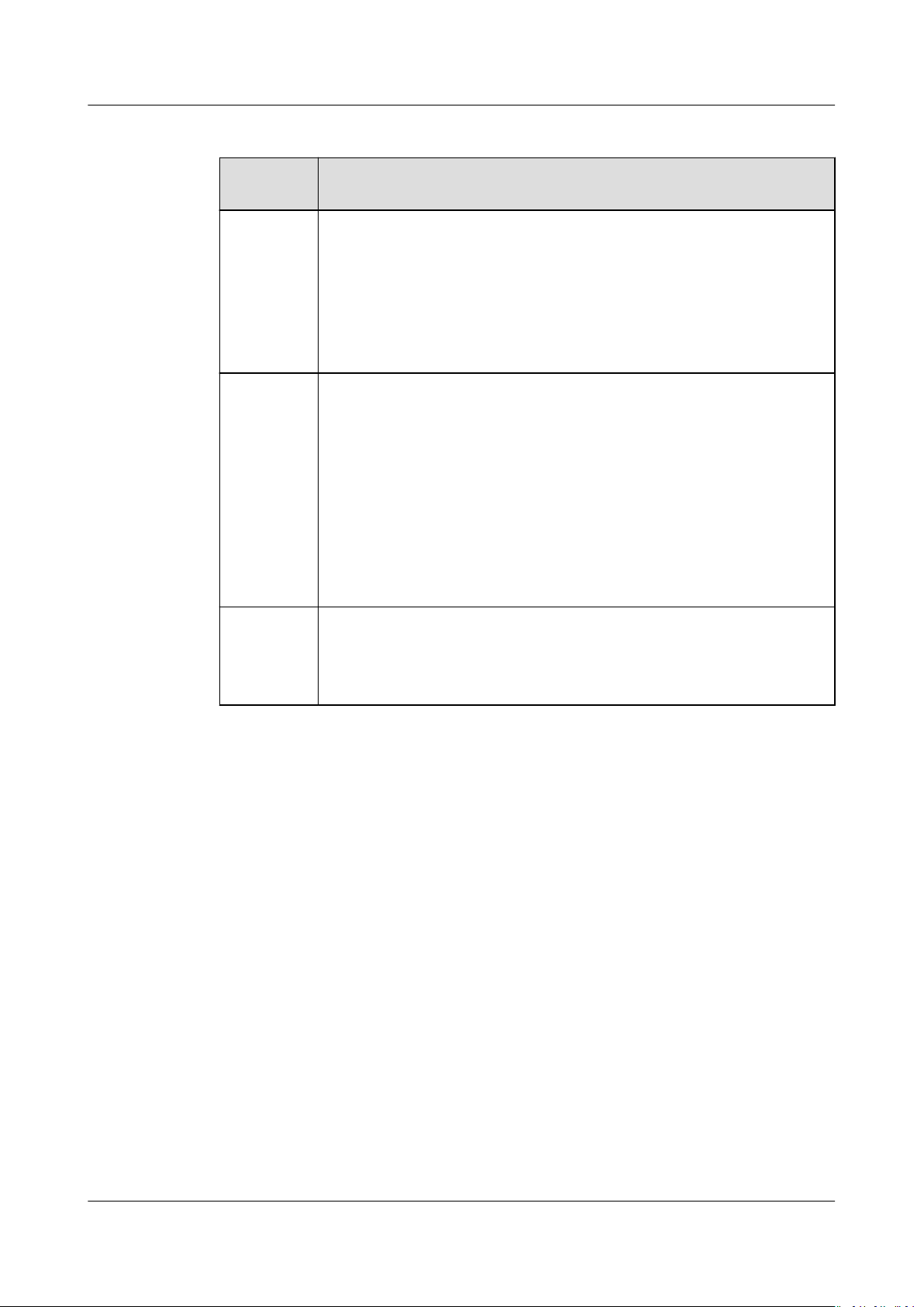
2.4.2 Working Modes
The SUN2000 can work in Standby, Operating, or Shutdown mode.
Figure 2-6 Working modes
Issue 03 (2022-08-30) Copyright © Huawei Technologies Co., Ltd. 12
SUN2000-(50KTL-ZHM3, 50KTL-M3)
User Manual 2 Overview
Table 2-2 Working mode description
Working
Description
Mode
Standby The SUN2000 enters Standby mode when the external
environment does not meet the operating requirements. In
Standby mode:
● The SUN2000 continuously performs status check and enters
the Operating mode once the operating requirements are met.
● The SUN2000 enters Shutdown mode after detecting a
shutdown command or a fault after startup.
Operating In Operating mode:
● The SUN2000 converts DC power from PV strings into AC power
and feeds the power to the power grid.
● The SUN2000 tracks the maximum power point to maximize
the PV string output.
● If the SUN2000 detects a fault or a shutdown command, it
enters the Shutdown mode.
● The SUN2000 enters Standby mode after detecting that the PV
string output power is not suitable for connecting to the power
grid for generating power.
Shutdown ● In Standby or Operating mode, the SUN2000 enters Shutdown
mode after detecting a fault or shutdown command.
● In Shutdown mode, the SUN2000 enters Standby mode after
detecting a startup command or that the fault is rectied.
Issue 03 (2022-08-30) Copyright © Huawei Technologies Co., Ltd. 13

SUN2000-(50KTL-ZHM3, 50KTL-M3)
User Manual 3 SUN2000 Storage
3 SUN2000 Storage
The following requirements should be met if the SUN2000 is not put into use
directly:
● Do not unpack the SUN2000.
● Keep the storage temperature at –40°C to +70°C and the humidity at 5%–
95% RH.
● Store the SUN2000 in a clean and dry place and protect it from dust and
water vapor corrosion.
● A maximum of six SUN2000s can be stacked. To avoid personal injury or
device damage, stack SUN2000s with caution to prevent them from falling
over.
● During the storage period, check the SUN2000 periodically (recommended:
every three months). If any rodent bites are found on the packing materials,
replace the packing materials immediately.
● If the SUN2000 has been stored for more than two years, it must be checked
and tested by professionals before being put into use.
Issue 03 (2022-08-30) Copyright © Huawei Technologies Co., Ltd. 14
NO TE
NO TE
SUN2000-(50KTL-ZHM3, 50KTL-M3)
User Manual 4 Installation
4 Installation
4.1 Checking Before Installation
Outer Packing Materials
Before unpacking the inverter, check the outer packing materials for damage, such
as holes and cracks, and check the inverter model. If any damage is found or the
inverter model is not what you requested, do not unpack the package and contact
your supplier as soon as possible.
You are advised to remove the packing materials within 24 hours before installing the
inverter.
Package Contents
After unpacking the inverter, check that the contents are intact and complete. If
any damage is found or any component is missing, contact your supplier.
For details about the number of contents, see the
Packing List
in the packing case.
Issue 03 (2022-08-30) Copyright © Huawei Technologies Co., Ltd. 15
SUN2000-(50KTL-ZHM3, 50KTL-M3)
User Manual 4 Installation
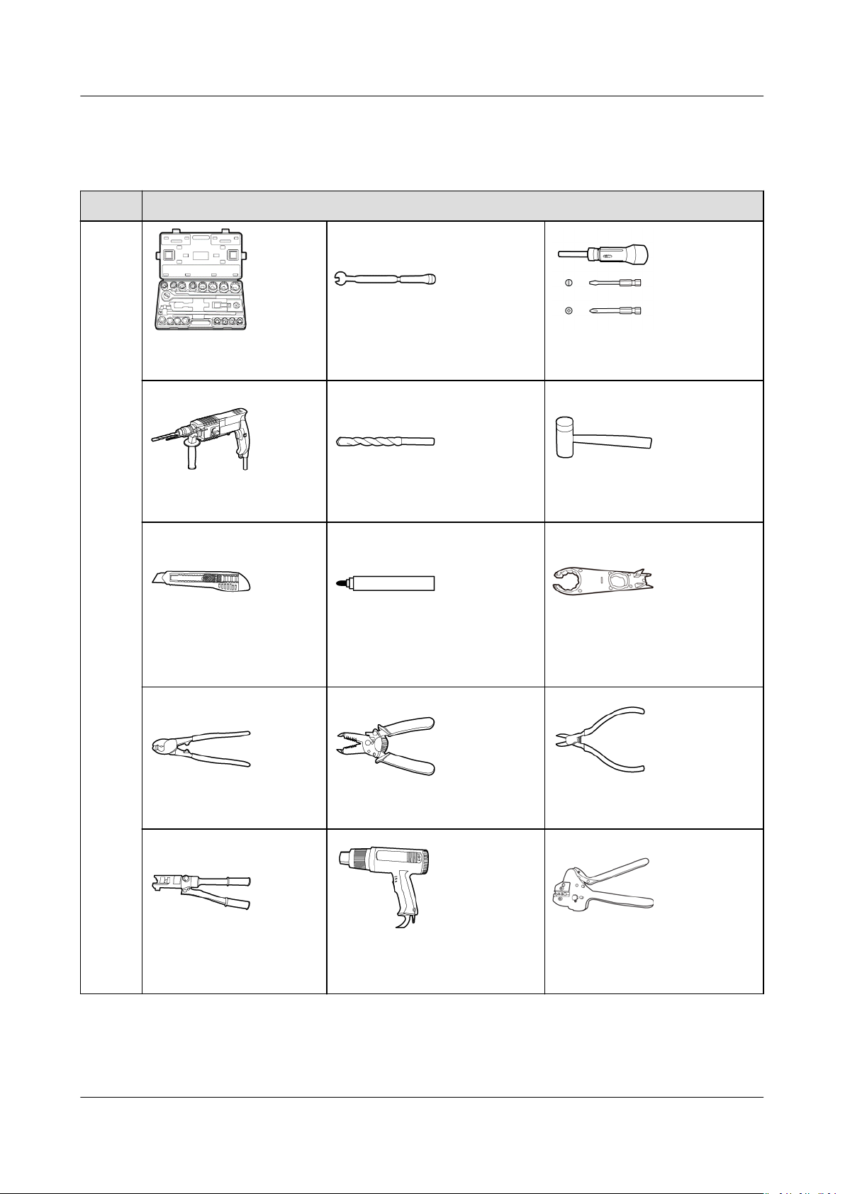
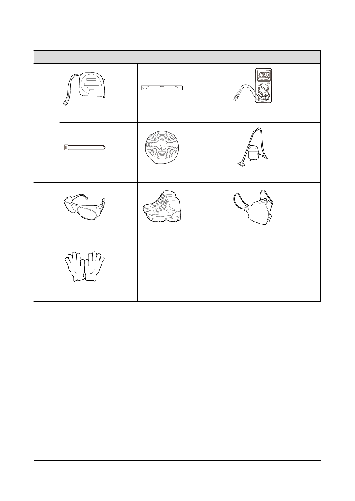
4.2 Tool Preparation
Type Tools and Instruments
Install
ation
Torque socket and
wrench
Hammer drill Drill bit Rubber mallet
Utility knife Marker
Torque wrench Torque screwdriver
Open-end wrench
H4TW0001 (Amphenol)
Cable cutter Wire stripper Diagonal pliers
Hydraulic pliers Heat gun
Issue 03 (2022-08-30) Copyright © Huawei Technologies Co., Ltd. 16
Crimping tool
H4TC0003 (Amphenol)
SUN2000-(50KTL-ZHM3, 50KTL-M3)
User Manual 4 Installation
Type Tools and Instruments
Steel measuring tape Level Multimeter
Cable tie Heat shrink tubing Vacuum cleaner
Person
al
protec
tive
equip
ment
(PPE)
Goggles Work shoes Dust mask
- -
Protective gloves
4.3 Selecting an Installation Position
Basic Requirements
● The SUN2000 is IP66-rated and can be installed indoors or outdoors.
● Do not install the SUN2000 in a place where a person can easily be exposed
to its enclosure and heat sinks, because these parts are extremely hot during
operation.
● Do not install the SUN2000 in areas with
● Do not install the equipment in an area with strong vibration, noise, or
electromagnetic interference.
ammable or explosive materials.
● If inverters are installed in a place with abundant vegetation, in addition to
routine weeding, harden the ground underneath the inverters using cement or
gravel (recommended area: 3 m x 2.5 m).
Issue 03 (2022-08-30) Copyright © Huawei Technologies Co., Ltd. 17
SUN2000-(50KTL-ZHM3, 50KTL-M3)
User Manual 4 Installation
● Do not install the SUN2000 in a place within children's reach.
● The SUN2000 will be corroded in salt areas, and the salt corrosion may cause
re. Do not install the SUN2000 outdoors in salt areas. A salt area refers to
the region within 500 m from the coast or prone to sea breeze. The eect
from sea breeze depends on weather conditions (such as typhoon and season
wind) or terrains (such as dams and hills).
Site Requirements
● The SUN2000 should be installed in a well-ventilated environment to ensure
good heat dissipation.
● If the SUN2000 is installed in a place exposed to direct sunlight, the power
may decrease as the temperature rises.
● You are advised to install the SUN2000 in a sheltered place or install an
awning over it.
Mounting Structure Requirements
● The mounting structure where the SUN2000 is installed must be
● Do not install the SUN2000 on ammable building materials.
● The SUN2000 is heavy. Ensure that the installation surface is solid enough to
bear the weight load.
● In residential areas, do not install the SUN2000 on drywalls or walls made of
similar materials which have a weak sound insulation performance because
the noise generated by the SUN2000 is noticeable.
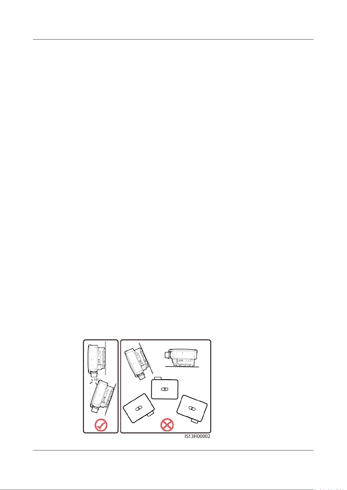
Installation Angle Requirements
The SUN2000 can be wall-mounted or support-mounted. Requirements for the
installation angle:
● Install the SUN2000 vertically or at a maximum back tilt of 15 degrees to
facilitate heat dissipation.
● Do not install the SUN2000 with a front tilt, excessive back tilt, side tilt,
horizontally, or upside down.
Figure 4-1 Installation angle
re resistant.
Issue 03 (2022-08-30) Copyright © Huawei Technologies Co., Ltd. 18

SUN2000-(50KTL-ZHM3, 50KTL-M3)
User Manual 4 Installation
Installation Space Requirements
● Reserve enough clearance around the SUN2000 to ensure sucient space for
installation and heat dissipation.
Figure 4-2 Installation space
● When installing multiple SUN2000s, install them in horizontal mode if ample
space is available and install them in triangle mode if no ample space is
available. Stacked installation is not recommended.
Figure 4-3 Horizontal installation (recommended)
Issue 03 (2022-08-30) Copyright © Huawei Technologies Co., Ltd. 19

SUN2000-(50KTL-ZHM3, 50KTL-M3)
User Manual 4 Installation
Figure 4-4 Two-layer triangle installation (recommended)
Figure 4-5 Three-layer triangle installation (not recommended)
Issue 03 (2022-08-30) Copyright © Huawei Technologies Co., Ltd. 20

NO TE
SUN2000-(50KTL-ZHM3, 50KTL-M3)
User Manual 4 Installation
Figure 4-6 Stacked installation (not recommended)
Figure 4-7 Back-to-back installation (not recommended)
The installation diagrams are for reference only and are irrelevant to the SUN2000
cascading scenario.
4.4 Moving the SUN2000
Procedure
Step 1 Lift the SUN2000 from the packing case and move it to the specied installation
position.
Issue 03 (2022-08-30) Copyright © Huawei Technologies Co., Ltd. 21

CA UTION
SUN2000-(50KTL-ZHM3, 50KTL-M3)
User Manual 4 Installation
● Move the SUN2000 with care to prevent device damage and personal injury.
● Do not use the wiring terminals and ports at the bottom to support any weight
of the SUN2000.
● Place a foam pad or cardboard under the SUN2000 to protect the SUN2000
enclosure from damage.
Figure 4-8 Moving the SUN2000
----End
4.5 Installing the Mounting Bracket
Installation Precautions
Before installing the mounting bracket, remove the security Torx wrench and set it
aside.
Figure 4-9 Position for binding the security Torx wrench
Issue 03 (2022-08-30) Copyright © Huawei Technologies Co., Ltd. 22

SUN2000-(50KTL-ZHM3, 50KTL-M3)
User Manual 4 Installation
(1) Security Torx wrench
Figure 4-10 shows the dimensions of the mounting holes for the SUN2000.
Figure 4-10 Mounting bracket dimensions
4.5.1 Support-mounted Installation
Procedure
Step 1 Secure the mounting bracket.
Figure 4-11 Securing the mounting bracket
Issue 03 (2022-08-30) Copyright © Huawei Technologies Co., Ltd. 23

NO TE
D ANGER
NO TICE
SUN2000-(50KTL-ZHM3, 50KTL-M3)
User Manual 4 Installation
You are advised to apply anti-rust paint on the hole positions for protection.
----End
4.5.2 Wall-mounted Installation
Prerequisites
To install the SUN2000, you need to prepare expansion bolts. M12x60 stainless
steel expansion bolts are recommended.
Procedure
Step 1 Determine the positions for drilling holes and mark the positions using a marker.
Step 2 Secure the mounting bracket.
Avoid drilling holes in the water pipes and cables buried in the wall.
Figure 4-12 Expansion bolt composition
(1) Bolt
(4) Flat washer (5) Expansion sleeve
● To prevent dust inhalation or contact with eyes, wear safety goggles and an
anti-dust mask when drilling holes.
● Clean up any dust in and around the holes using a vacuum cleaner and
measure the distance between holes. If the holes are inaccurately positioned,
drill holes again.
● Level the front of the expansion sleeve with the concrete wall after removing
the bolt, spring washer, and
not be securely installed on the concrete wall.
(2) Nut (3) Spring washer
at washer. Otherwise, the mounting bracket will
Issue 03 (2022-08-30) Copyright © Huawei Technologies Co., Ltd. 24

NO TE
SUN2000-(50KTL-ZHM3, 50KTL-M3)
User Manual 4 Installation
Figure 4-13 Installing expansion bolts
----End
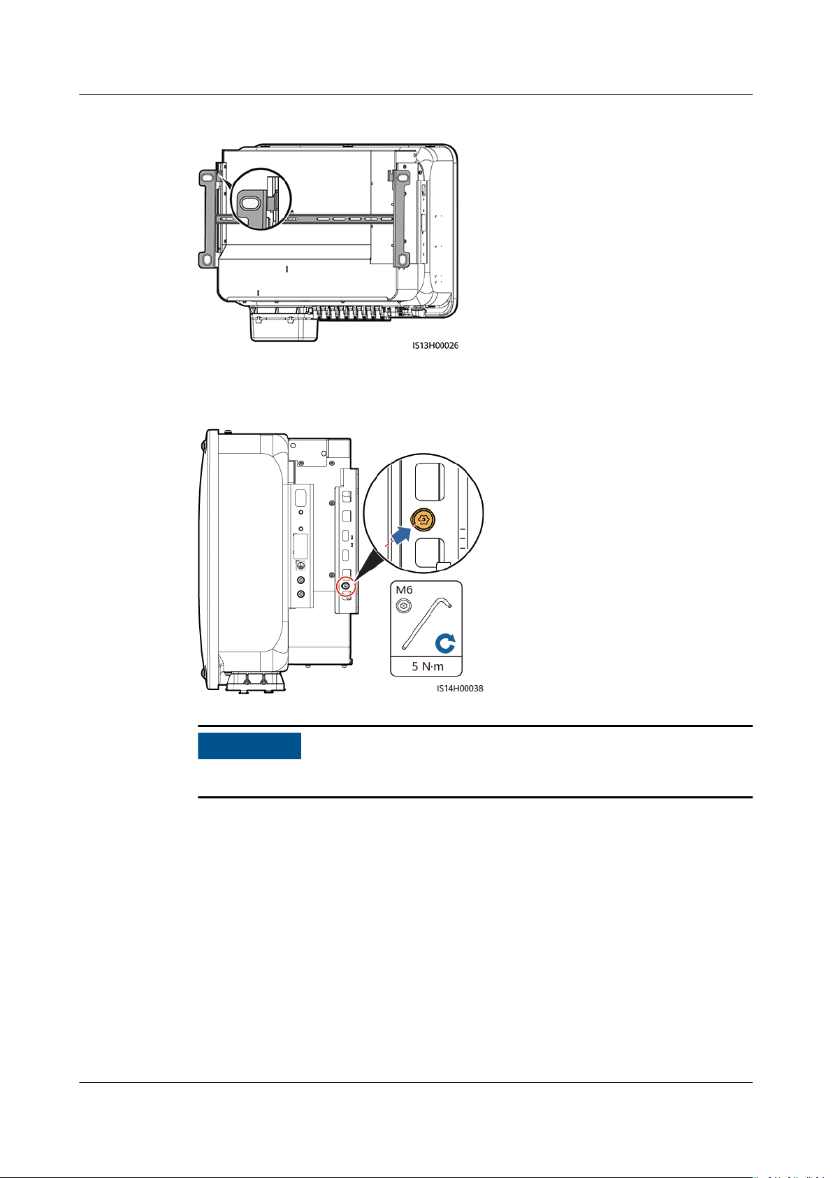
4.6 Installing a SUN2000
Step 1 (Optional) Install the locking screw for the DC switch.
● The DC switch locking screw is used to lock the DC switch to prevent the switch from
rotating.
● For models used in Australia, install the DC switch locking screw according to local
standards. The DC switch locking screw is delivered with the SUN2000.
Figure 4-14 Installing the locking screw for the DC switch
Step 2 Install the SUN2000 onto the mounting bracket.
Issue 03 (2022-08-30) Copyright © Huawei Technologies Co., Ltd. 25
NO TICE
SUN2000-(50KTL-ZHM3, 50KTL-M3)
User Manual 4 Installation
Figure 4-15 Installing a SUN2000
Step 3 Tighten the nuts on both sides of the SUN2000.
Figure 4-16 Tightening the nut
Secure the screws on the sides before connecting cables.
----End
Issue 03 (2022-08-30) Copyright © Huawei Technologies Co., Ltd. 26

D ANGER
WARNING
NO TE
SUN2000-(50KTL-ZHM3, 50KTL-M3)
User Manual 5 Electrical Connections
5 Electrical Connections
5.1 Precautions
When exposed to sunlight, the PV arrays supply DC voltage to the SUN2000.
Before connecting cables, ensure that the two DC switches on the SUN2000 are
OFF. Otherwise, the high voltage of the SUN2000 may result in electric shocks.
● The equipment damage caused by incorrect cable connections is beyond the
warranty scope.
● Only certied electrician can perform electrical terminations.
● Wear proper PPE at all time when terminating cables.
● To prevent poor cable connection due to overstress, it is recommended that the
cables be bent and reserved, and then connected to the appropriate ports.
The cable colors shown in the electrical connection diagrams provided in this chapter are
for reference only. Select cables in accordance with local cable specications (green-andyellow cables are only used for grounding).
Issue 03 (2022-08-30) Copyright © Huawei Technologies Co., Ltd. 27
SUN2000-(50KTL-ZHM3, 50KTL-M3)
User Manual 5 Electrical Connections
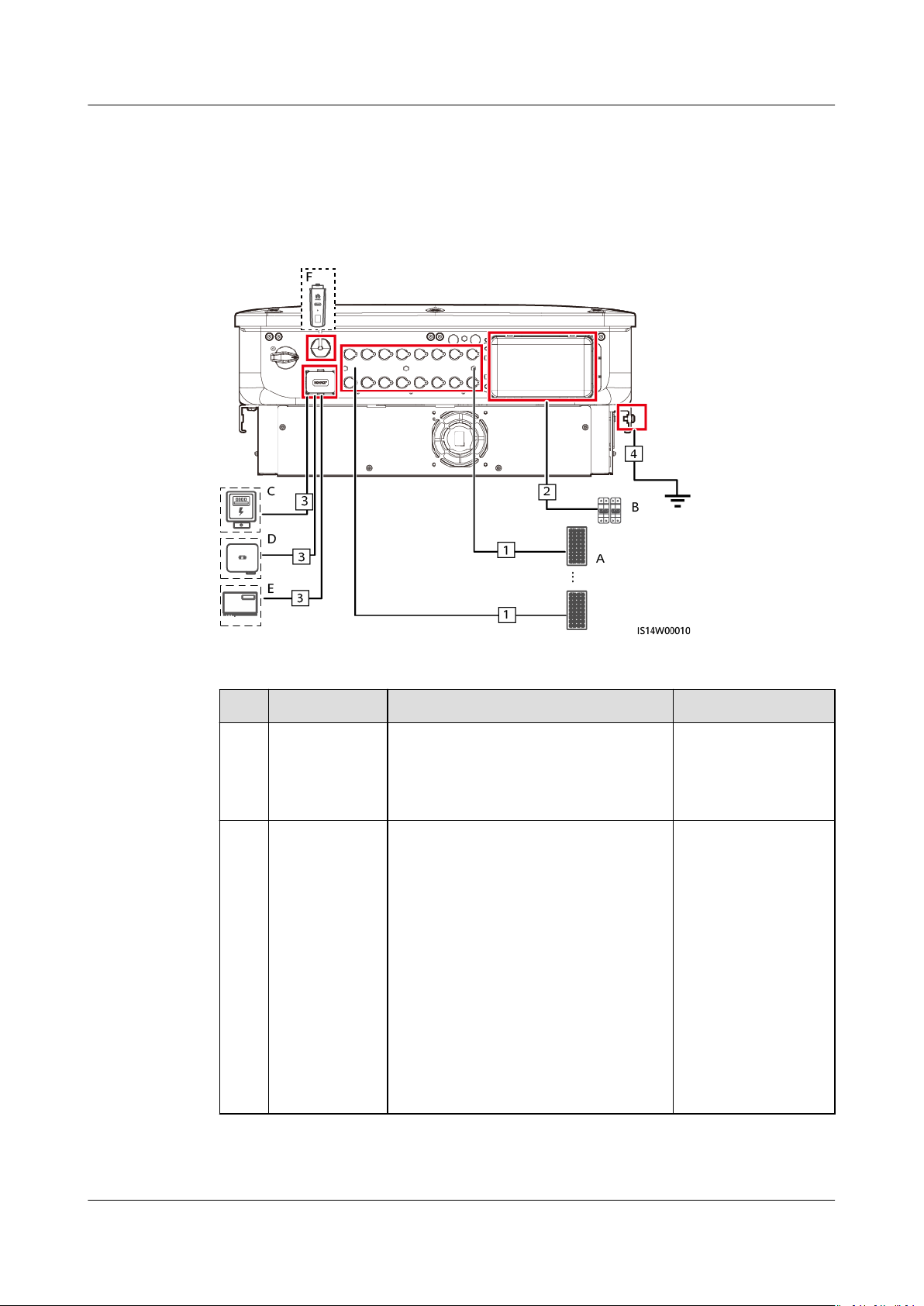
5.2 Preparing Cables
Figure 5-1 SUN2000 cable connections (dashed boxes indicate optional
components)
Table 5-1 Components
No.
A PV string ● A PV string consists of PV
B AC switch To ensure that the inverter can be
Component Description Source
modules connected in series.
● The SUN2000 supports the input
from eight PV strings.
safely disconnected from the power
grid when an exception occurs,
connect an AC switch to the AC side
of the inverter. Select an
appropriate AC switch in
accordance with local industry
standards and regulations. Huawei
recommends the following switch
specications:
Recommended: a three-phase AC
circuit breaker with a rated voltage
greater than or equal to 500 V AC
and a rated current of 125 A.
Prepared by users
Prepared by users
Issue 03 (2022-08-30) Copyright © Huawei Technologies Co., Ltd. 28
NO TICE
SUN2000-(50KTL-ZHM3, 50KTL-M3)
User Manual 5 Electrical Connections
No. Component Description Source
C Power
meter
[1]
The SUN2000 can connect to the
DTSU666-H, DTSU666-HW, and
YDS60-80 power meters.
[2]
Purchased from
Huawei
D SUN2000 Select a proper model as required. Purchased from
Huawei
E SmartLogger SmartLogger3000 Purchased from
Huawei
F Smart
Dongle
Note [1]: For details about meter operations, see
Select a proper model as required. Purchased from
Huawei
DTSU666-HW Smart Power
Sensor Quick Guide, YDS60-80 Smart Power Sensor Quick Guide, DTSU666H and DTSU666-H 250 A (50 mA) Smart Power Sensor Quick Guide
DTSU666-H 100 A and 250 A Smart Power Sensor User Manual
and
.
Note [2]: SUN2000MA V100R001C20SPC116 and later versions can connect to
DTSU666-HW and YDS60-80 power meter.
The cable specications must comply with local standards. Device damage caused
by using cables with incorrect specications will not be covered by the warranty.
Table 5-2 Cable description
No.
Cable Type Recommended
Source
Specications
1 DC input
power
cable
Common PV cable in the
industry
(Recommended model:
PV1-F)
● Conductor crosssectional area: 4–6
2
mm
● Cable outer
Prepare
d by
users
diameter: 5.5–9
mm
2 AC
output
power
cable
Outdoor copper-core/
aluminum-core cable
● Conductor crosssectional area: 25–
50 mm2 outdoor
copper-core cable
or 35–50 mm
2
Prepare
d by
users
outdoor aluminumcore cable
[1]
● Cable outer
diameter: 16–38
mm
Issue 03 (2022-08-30) Copyright © Huawei Technologies Co., Ltd. 29
D ANGER
NO TE
NO TICE
SUN2000-(50KTL-ZHM3, 50KTL-M3)
User Manual 5 Electrical Connections
No. Cable Type Recommended
3 (Option
al)
Signal
cable
Two-core outdoor
shielded twisted pair
(recommended model:
DJYP2VP2-2x2x0.75)
4 PE cable Single-core outdoor
copper-core cable
Note [1]: Five-core cables with a cross-sectional area of 5 x 35 mm2 or 5 x 50
mm2 are not supported.
5.3 Connecting the PE Cable
Specications
● Conductor crosssectional area: 0.2–
2
1 mm
● Cable outer
diameter: 4–11 mm
Conductor crosssectional area ≥ 16
2
mm
Source
Prepare
d by
users
Prepare
d by
users
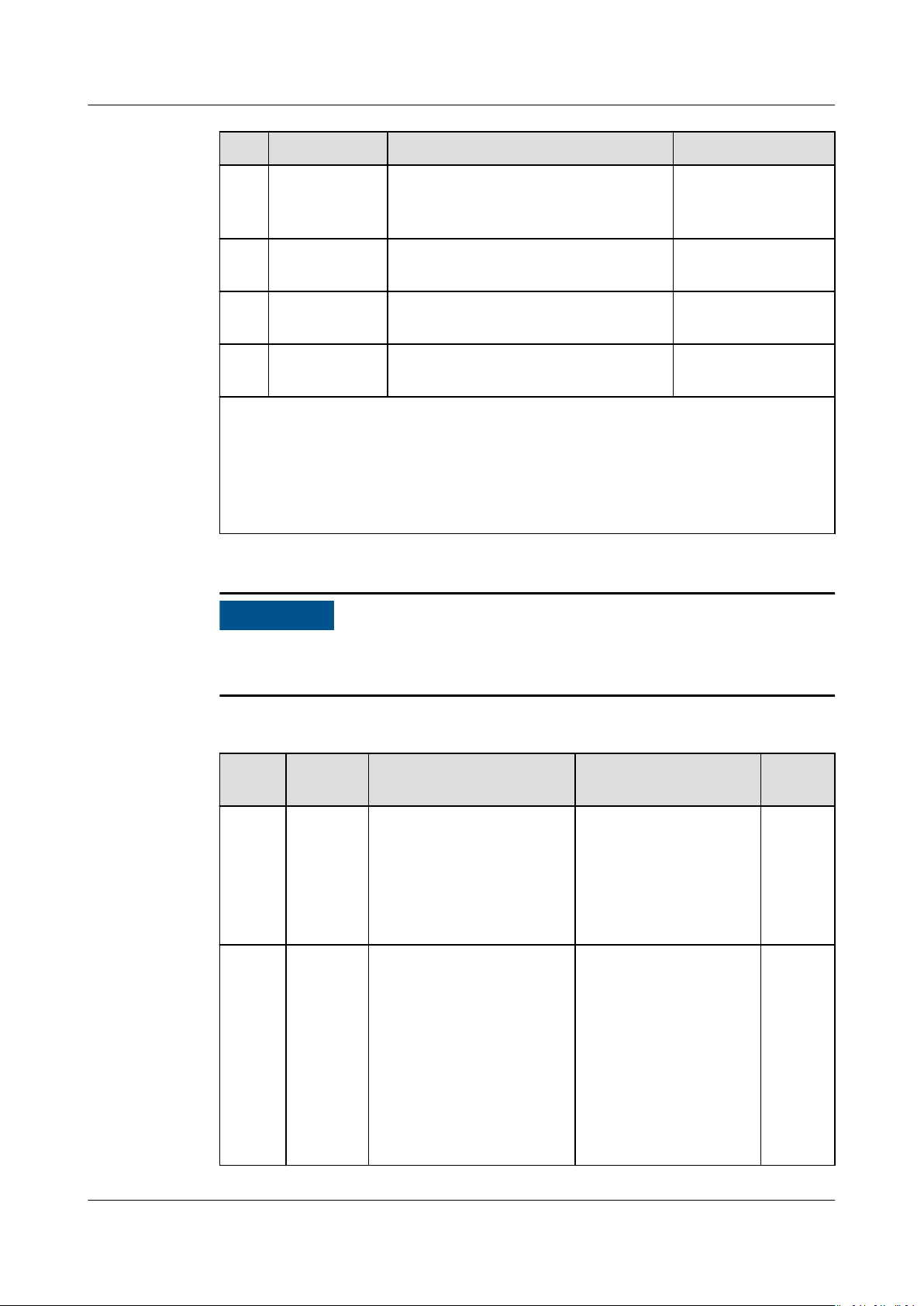
Procedure
Step 1 Crimp OT terminals.
● Ensure that the PE cable is securely connected. Otherwise, electric shocks may
occur.
● Do not connect the neutral wire to the enclosure as a PE cable. Otherwise,
electric shocks may occur.
● The PE point at the AC output port is used only as a PE equipotential point, not a
substitute for the PE point on the enclosure.
● It is recommended that silicone sealant or paint be applied around the ground terminal
after the PE cable is connected.
● Avoid scratching the core wire when stripping a cable.
● The cavity formed after the conductor crimp strip of the OT terminal is crimped
must wrap the core wires completely. The core wires must contact the OT
terminal closely.
● Wrap the wire crimping area with heat shrink tubing or PVC insulation tape.
The heat shrink tubing is used as an example.
● When using a heat gun, protect devices from being scorched.
Issue 03 (2022-08-30) Copyright © Huawei Technologies Co., Ltd. 30
SUN2000-(50KTL-ZHM3, 50KTL-M3)
User Manual 5 Electrical Connections
Figure 5-2 Crimping an OT terminal
(1) Cable (2) Core (3) Heat shrink tubing
(4) OT terminal (5) Crimping tool (6) Heat gun
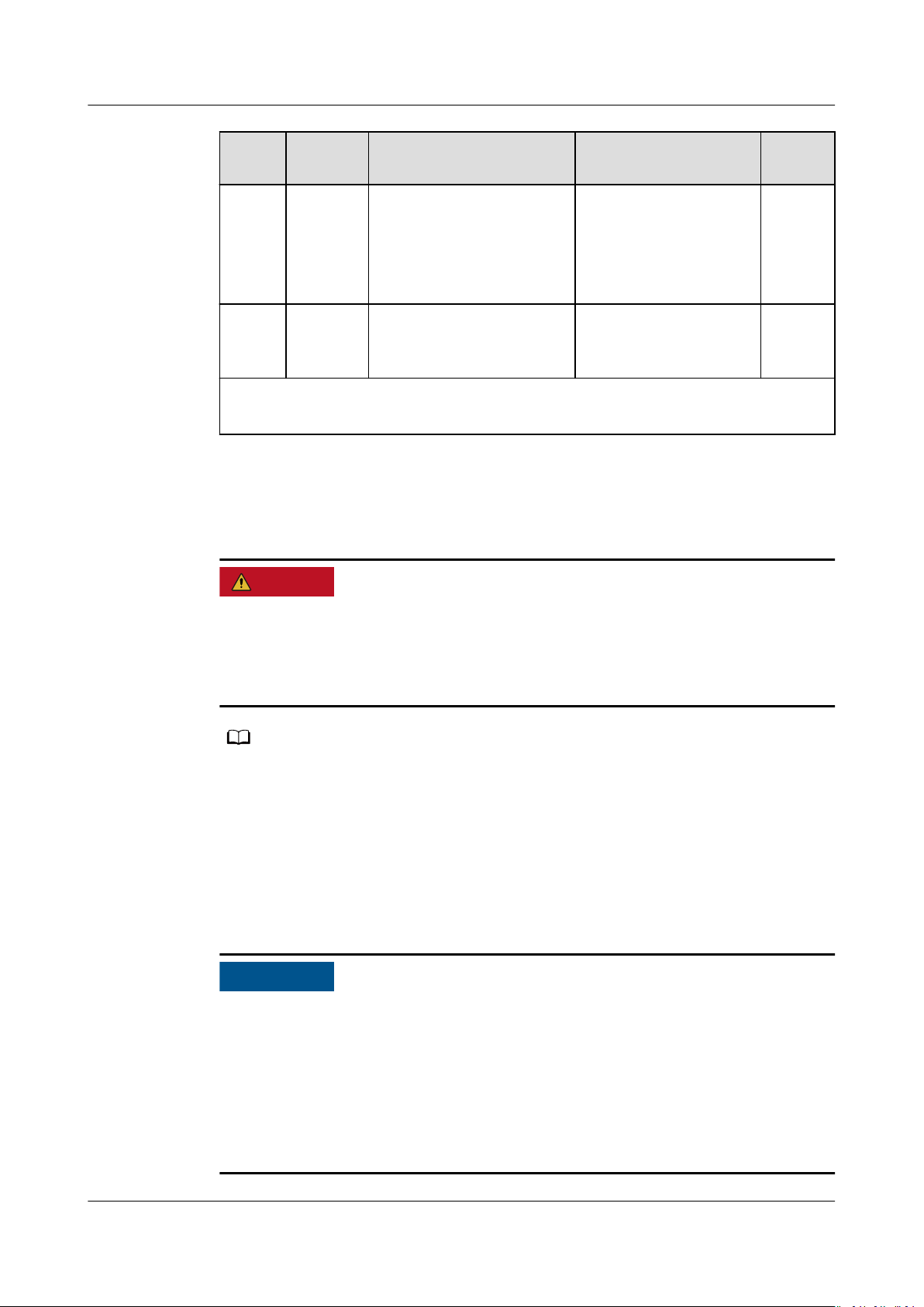
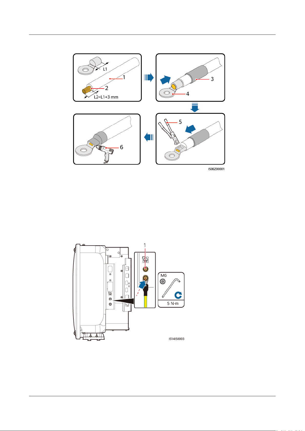
Step 2 Connect the PE cable.
Figure 5-3 Connecting the PE cable
(1) Reserved PE point
----End
Issue 03 (2022-08-30) Copyright © Huawei Technologies Co., Ltd. 31

WARNING
CA UTION
NO TICE
SUN2000-(50KTL-ZHM3, 50KTL-M3)
User Manual 5 Electrical Connections
5.4 Connecting the AC Output Power Cable
Precautions
An AC switch must be installed on the AC side of the SUN2000 to ensure that the
SUN2000 can be safely disconnected from the power grid.
● Do not connect loads between the inverter and the AC switch that directly
connects to the inverter. Otherwise, the switch may trip by mistake.
● If an AC switch is used with specications beyond local standards, regulations,
or Huawei's recommendations, the switch may fail to turn
manner in case of exceptions, causing serious faults.
o in a timely
Each inverter must be equipped with an AC output switch. Multiple inverters
cannot connect to the same AC output switch.
● If the external AC switch can perform earth leakage protection, the rated
leakage action current should be greater than or equal to 500 mA.
● If multiple SUN2000s connect to the general residual current device (RCD)
through their respective external AC switches, the rated leakage action current
of the general RCD should be greater than or equal to the number of
SUN2000s multiplied by 500 mA.
● Use a socket wrench and extension rod to connect the AC power cable. The
extension rod must be longer than or equal to 100 mm.
Sucient slack should be provided in the PE cable to ensure that the last cable
●
bearing the force is the PE cable when the AC output power cable bears pulling
force due to force majeure.
● Do not install third-party devices in the AC connection box.
● You need to prepare M8 OT terminals by yourself.
● If the AC MBUS is used, multi-core cables are recommended, supporting a
maximum communication distance of 1000 m. To use other types of AC power
cables, contact the Company's technical support.
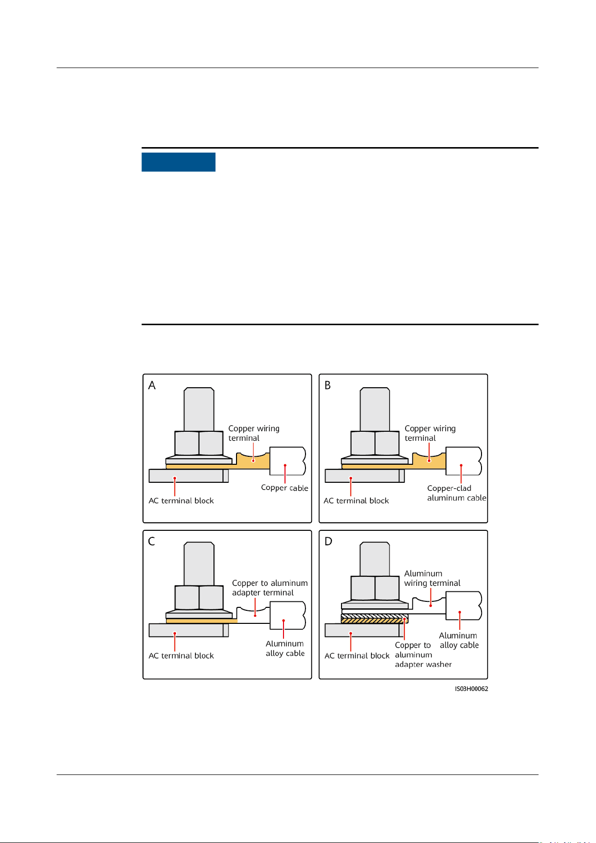
Requirements for the OT or DT Terminal
● If a copper cable is used, use copper wiring terminals.
● If a copper-clad aluminum cable is used, use copper wiring terminals.
Issue 03 (2022-08-30) Copyright © Huawei Technologies Co., Ltd. 32
NO TICE
SUN2000-(50KTL-ZHM3, 50KTL-M3)
User Manual 5 Electrical Connections
● If an aluminum alloy cable is used, use copper-aluminum transition wiring
terminals, or aluminum wiring terminals along with copper-aluminum
transition spacers.
● Do not connect aluminum wiring terminals to the AC terminal block. Otherwise
the electrochemical corrosion will occur and aect the reliability of cable
connections.
● Comply with the IEC61238-1 requirements when using copper-aluminum
transition wiring terminals, or aluminum wiring terminals along with copperaluminum transition spacers.
● If copper-aluminum transition spacers are used, pay attention to the front and
rear sides. Ensure that the aluminum sides of spacers are in contact with
aluminum wiring terminals, and copper sides of spacers are in contact with the
AC terminal block.
Figure 5-4 Requirements for the OT/DT terminal
Procedure
Step 1 Remove the AC terminal box and install partition boards.
Issue 03 (2022-08-30) Copyright © Huawei Technologies Co., Ltd. 33

NO TE
SUN2000-(50KTL-ZHM3, 50KTL-M3)
User Manual 5 Electrical Connections
Figure 5-5 Removing the AC terminal box
Step 2 Connect the AC output power cable.
● To avoid damaging the rubber liner, do not route a cable with a crimped OT terminal
directly through it.
● It is recommended that the length of the PE cable to be stripped be 15 mm longer than
the length of other cables.
● The cable colors in gures are for reference only. Select appropriate cables according to
the local standards.
Figure 5-6 Stripping the AC power cable (using a ve-core cable as an example)
Issue 03 (2022-08-30) Copyright © Huawei Technologies Co., Ltd. 34

SUN2000-(50KTL-ZHM3, 50KTL-M3)
User Manual 5 Electrical Connections
Figure 5-7 Five-core cable (L1, L2, L3, N, and PE)
Figure 5-8 Four-core cable (L1, L2, L3, and PE)
Issue 03 (2022-08-30) Copyright © Huawei Technologies Co., Ltd. 35

SUN2000-(50KTL-ZHM3, 50KTL-M3)
User Manual 5 Electrical Connections
Figure 5-9 Four-core cable (L1, L2, L3, and N)
Figure 5-10 Three-core cable (L1, L2, and L3)
Issue 03 (2022-08-30) Copyright © Huawei Technologies Co., Ltd. 36

D ANGER
SUN2000-(50KTL-ZHM3, 50KTL-M3)
User Manual 5 Electrical Connections
Figure 5-11 Wiring requirements
----End
5.5 Installing the DC Input Power Cable
Precautions
● Before connecting the DC input power cables, ensure that the DC voltage is
within the safe range (lower than 60 V DC) and that the DC switch on the
SUN2000 is OFF. Failing to do so may result in electric shocks.
● When the SUN2000 is running, it is not allowed to work on the DC input power
cables, such as connecting or disconnecting a PV string or a PV module in a PV
string. Failing to do so may cause electric shocks.
● If no PV string connects to a DC input terminal of the SUN2000, do not remove
the watertight cap from the DC input terminals. Otherwise, the IP rating of the
SUN2000 will be
aected.
Issue 03 (2022-08-30) Copyright © Huawei Technologies Co., Ltd. 37

WARNING
NO TICE
SUN2000-(50KTL-ZHM3, 50KTL-M3)
User Manual 5 Electrical Connections
Ensure that the following conditions are met. Otherwise, the SUN2000 may be
damaged, or even a re could happen.
● PV modules connected in series in each PV string are of the same specications.
● The DC input voltage of the SUN2000 shall not exceed 1100 V DC under any
circumstance.
● The polarities of electric connections are correct on the DC input side. The
positive and negative terminals of a PV string connect to corresponding positive
and negative DC input terminals of the SUN2000.
● If polarity of the DC input power cable is reversed and the DC switch is ON, do
not turn
o the DC switch immediately or remove positive and negative
connectors. Wait until the solar irradiance declines at night and the PV string
current reduces to below 0.5 A, and then turn
o the DC switch and remove
the positive and negative connectors. Correct the PV string polarity before
reconnecting the PV string to the SUN2000.
● The SUN2000 does not support power supplies other than PV strings. Since the
output of the PV string connected to the SUN2000 cannot be grounded, ensure
that the PV module output is well insulated to ground.
● During the installation of PV strings and the SUN2000, the positive or negative
terminals of PV strings may be short-circuited to ground if the power cable is
not properly installed or routed. In this case, an AC or DC short circuit may
occur and damage the SUN2000. The caused device damage is not covered
under any warranty.
Figure 5-12 DC input terminals
When the DC input is not fully congured, the DC input terminals must meet the
following requirements:
1. Distribute the DC input power cables evenly over four MPPT circuits, and
connect them preferentially through MPPT1 and MPPT4.
2. Maximize the number of connected MPPT circuits.
Number
of PV
Strings
Terminal Selection Number
of PV
Strings
Terminal Selection
1 PV1 2 PV1 and PV7
Issue 03 (2022-08-30) Copyright © Huawei Technologies Co., Ltd. 38

CA UTION
NO TICE
SUN2000-(50KTL-ZHM3, 50KTL-M3)
User Manual 5 Electrical Connections
Procedure
Step 1 Connect the DC power cable.
Number
of PV
Strings
Terminal Selection Number
of PV
Strings
Terminal Selection
3 PV1, PV3 and PV7 4 PV1, PV3, PV5 and PV7
5 PV1, PV2, PV3, PV5 and
PV7
7 PV1, PV2, PV3, PV4, PV5,
PV7 and PV8
6 PV1, PV2, PV3, PV5, PV7
and PV8
8 PV1, PV2, PV3, PV4, PV5,
PV6, PV7 and PV8
Use the positive and negative Amphenol Helios H4 metal terminals and DC
connectors supplied with the solar inverter. Using incompatible positive and
negative metal terminals and DC connectors may result in serious consequences.
The caused device damage is not covered under any warranty.
● You are advised to use the H4TC0003 (Amphenol) crimping tool and do not use
it with the positioning block. Otherwise, the metal terminals may be damaged.
● The H4TW0001 (Amphenol) open-end wrench is recommended.
● Cables with high rigidity, such as armored cables, are not recommended as DC
input power cables, because poor contact may be caused by the bending of the
cables.
● Before assembling DC connectors, label the cable polarities correctly to ensure
correct cable connections.
● After the positive and negative connectors snap into place, pull the DC input
cables back to ensure that they are connected securely.
Issue 03 (2022-08-30) Copyright © Huawei Technologies Co., Ltd. 39

NO TICE
NO TE
SUN2000-(50KTL-ZHM3, 50KTL-M3)
User Manual 5 Electrical Connections
Figure 5-13 Connecting the DC power cable
During DC input power cabling, leave at least 50 mm of slack. The axial tension
on PV connectors must not exceed 80 N. Radial stress or torque must not be
generated on PV connectors.
----End
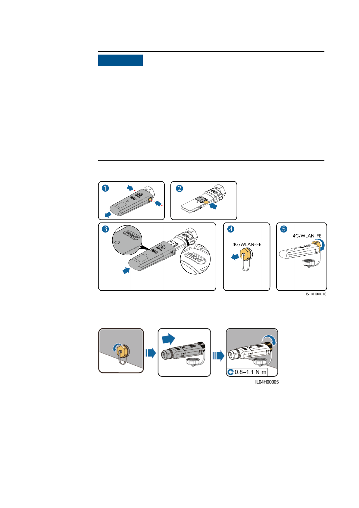
5.6 (Optional) Installing the Smart Dongle
Procedure
The Smart Dongle is not provided in standard conguration.
● 4G Smart Dongle
Issue 03 (2022-08-30) Copyright © Huawei Technologies Co., Ltd. 40
NO TICE
SUN2000-(50KTL-ZHM3, 50KTL-M3)
User Manual 5 Electrical Connections
● If your Smart Dongle is not equipped with a SIM card, prepare a standard
SIM card (size: 25 mm x 15 mm) with the capacity greater than or equal to
64 KB.
● When installing the SIM card, determine its installation direction based on
the silk screen and arrow on the card slot.
● Press the SIM card in place to lock it, indicating that the SIM card is
correctly installed.
● When removing the SIM card, push it inwards to eject it.
● When reinstalling the cover of the Smart Dongle, ensure that the buckle
springs back in place.
Figure 5-14 Installing a 4G Smart Dongle
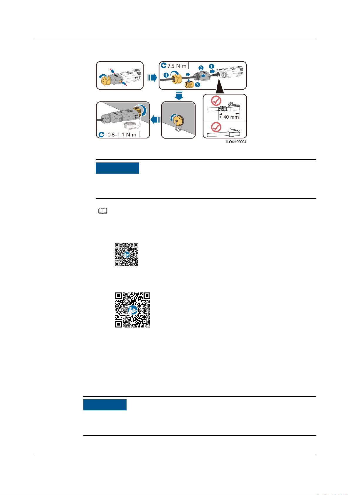
● WLAN-FE Smart Dongle (WLAN Communication)
Figure 5-15 Installing a WLAN-FE Smart Dongle (WLAN communication)
● WLAN-FE Smart Dongle (FE Communication)
Issue 03 (2022-08-30) Copyright © Huawei Technologies Co., Ltd. 41
NO TICE
NO TE
NO TICE
SUN2000-(50KTL-ZHM3, 50KTL-M3)
User Manual 5 Electrical Connections
Figure 5-16 Installing a WLAN-FE Smart Dongle (FE communication)
Install the network cable before installing the Smart Dongle on the solar
inverter.
● For details about how to operate the WLAN-FE Smart Dongle SDongleA-05, see
SDongleA-05 Smart Dongle Quick Guide (WLAN-FE)
below to obtain the document.
● For details about how to operate the 4G Smart Dongle SDongleA-03, see
SDongleA-03 Quick Guide (4G)
document.
The quick guide is delivered with the Smart Dongle.
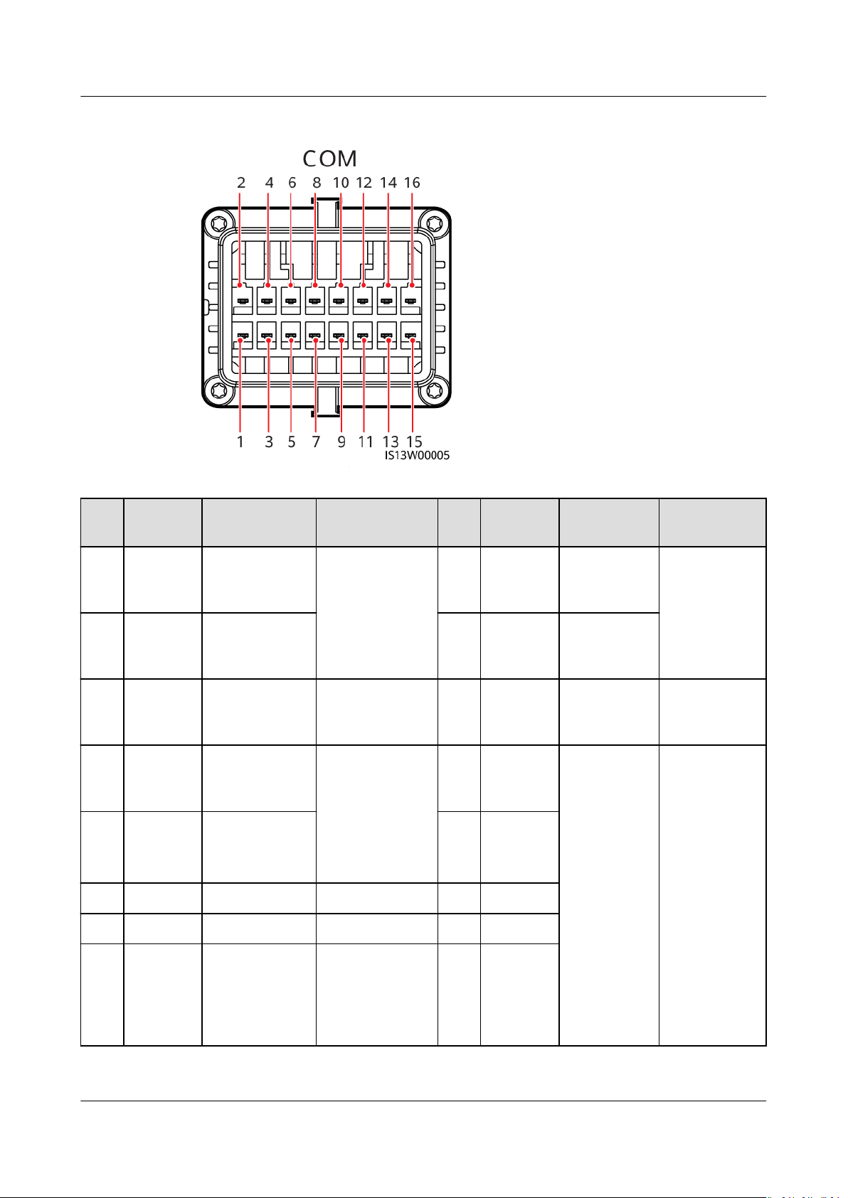
5.7 Connecting the Signal Cable
COM Port Pin
Denitions
. You can scan the QR code
. You can scan the QR code below to obtain the
When laying out a signal cable, separate it from power cables to avoid strong
signal interference.
Issue 03 (2022-08-30) Copyright © Huawei Technologies Co., Ltd. 42
SUN2000-(50KTL-ZHM3, 50KTL-M3)
User Manual 5 Electrical Connections
Figure 5-17 Pin denitions
Pin DenitionFunction Description Pin DenitionFunction Description
1 485A1_1 RS485
dierential
signal +
3 485B1_1 RS485
dierential
signal –
5 PE Ground point
on the shield
layer
7 485A2 RS485
dierential
signal +
9 485B2 RS485
dierential
signal –
Used to
cascade
inverters or
2 485A1_2 RS485
dierential
signal +
connect to the
SmartLogger.
4 485B1_2 RS485
dierential
signal –
- 6 PE Ground
point on the
shield layer
Connects to
the RS485
signal port for
controlling the
power meter at
8 DIN1 Dry contact
for power
grid
scheduling
10 DIN2
the grid-tied
point.
Used to
cascade
inverters or
connect to
the
SmartLogger.
-
-
11 - - - 12 DIN3
13 GND GND - 14 DIN4
15 DIN5 NS
protection/
OVGR
Supports
functions such
as NS
16 GND
protection, and
OVGR.
Issue 03 (2022-08-30) Copyright © Huawei Technologies Co., Ltd. 43
NO TICE
SUN2000-(50KTL-ZHM3, 50KTL-M3)
User Manual 5 Electrical Connections
Scenarios Where No Signal Cable Is Connected
If no signal cable is required for the SUN2000, use waterproof plugs to block the
wiring holes on the signal cable connector and connect the signal cable connector
to the communications port on the SUN2000 to improve the waterproof
performance of the SUN2000.
Figure 5-18 Securing the signal cable connector
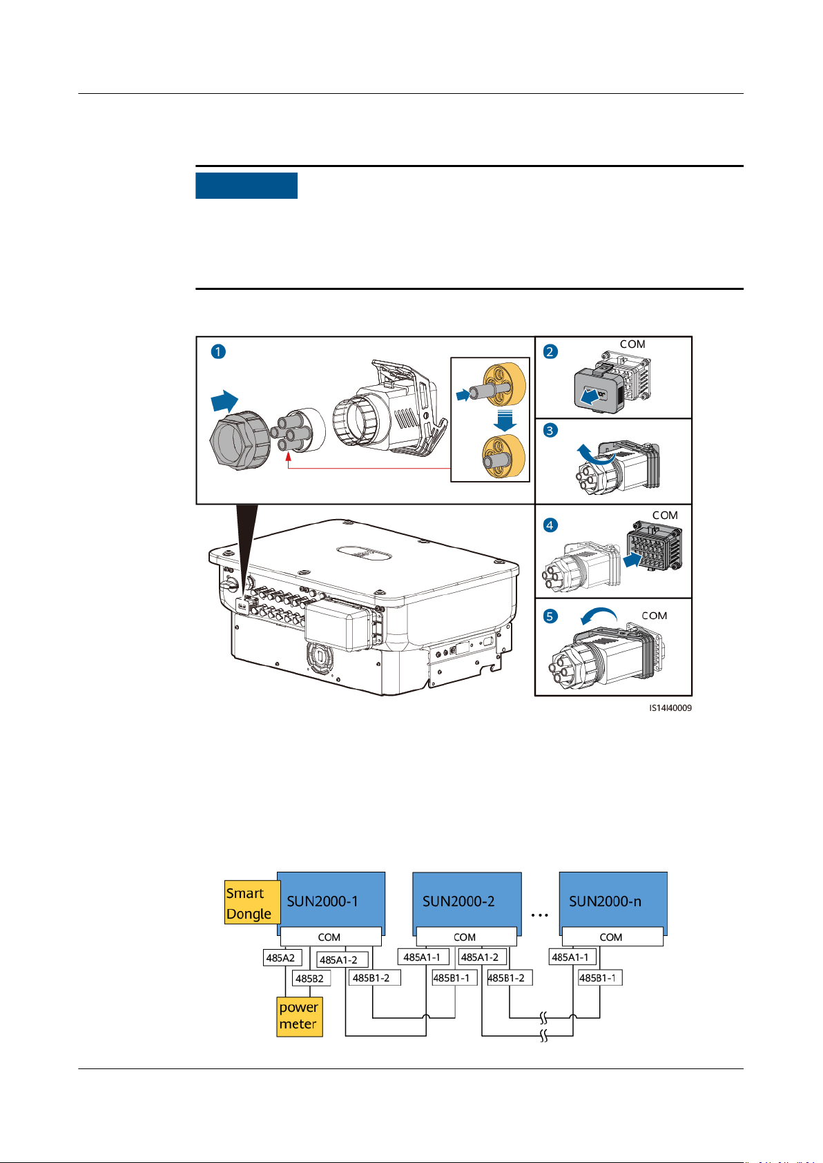
5.7.1 Communication Modes
RS485 Communication
● Smart Dongle networking
Figure 5-19 Smart Dongle networking
Issue 03 (2022-08-30) Copyright © Huawei Technologies Co., Ltd. 44
NO TE
NO TE
NO TE
SUN2000-(50KTL-ZHM3, 50KTL-M3)
User Manual 5 Electrical Connections
If a SUN2000 is networked using a Smart Dongle, it cannot be connected to the
SmartLogger.
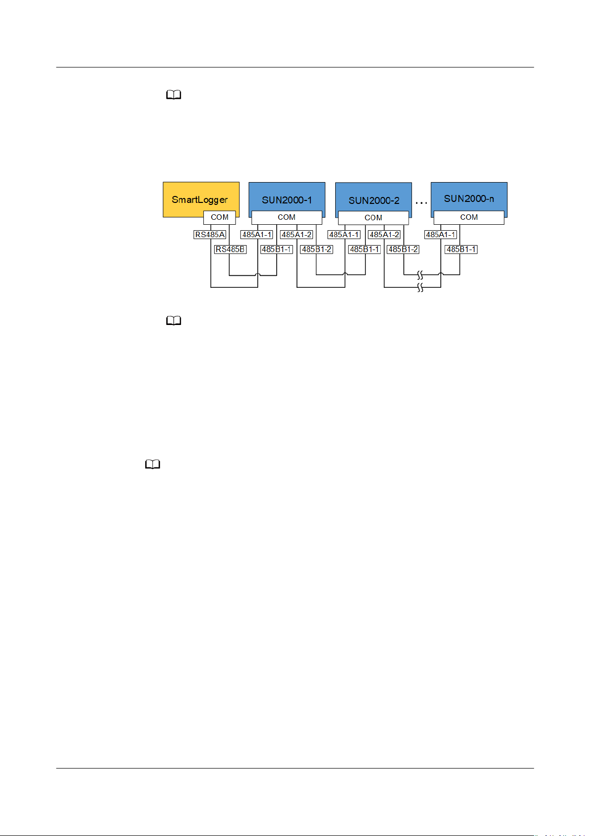
● SmartLogger networking
Figure 5-20 SmartLogger networking
● If a SUN2000 is networked using the SmartLogger, it cannot be connected to a
● It is recommended that the number of SUN2000s connected to each RS485 route
MBUS Communication
The MBUS is a communication mode in which communication signals are loaded
to power cables through the communications board for transmission.
● The built-in MBUS module in the SUN2000 does not need to be connected with cables.
● In utility-scale scenarios, an isolation transformer must be connected between inverters
and loads.
● Commercial and industrial scenarios are supported only in China.
Smart Dongle.
be less than 30.
Issue 03 (2022-08-30) Copyright © Huawei Technologies Co., Ltd. 45

SUN2000-(50KTL-ZHM3, 50KTL-M3)
User Manual 5 Electrical Connections
Figure 5-21 MBUS communication (utility-scale scenarios)
Figure 5-22 MBUS communication (commercial and industrial scenarios in China)
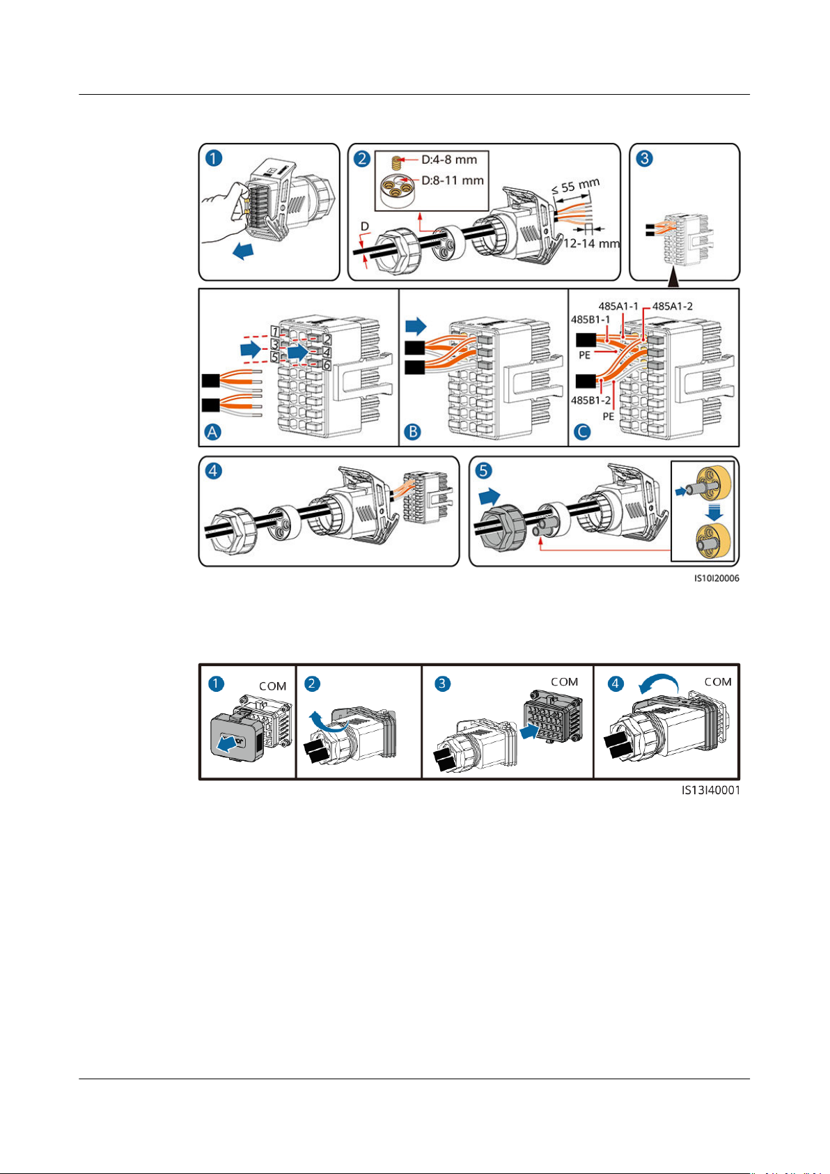
5.7.2 (Optional) Connecting the RS485 Communications Cable to the SUN2000
Procedure
Step 1 Connect the signal cable to the signal cable connector.
Issue 03 (2022-08-30) Copyright © Huawei Technologies Co., Ltd. 46
SUN2000-(50KTL-ZHM3, 50KTL-M3)
User Manual 5 Electrical Connections
Figure 5-23 Connecting the cable
Step 2 Connect the signal cable connector to the COM port.
Figure 5-24 Securing the signal cable connector
----End
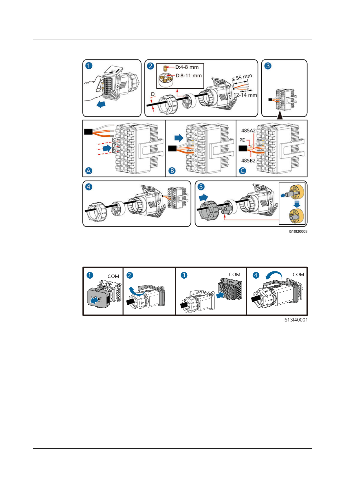
5.7.3 (Optional) Connecting the RS485 Communications Cable to the Power Meter
Procedure
Step 1 Connect the signal cable to the signal cable connector.
Issue 03 (2022-08-30) Copyright © Huawei Technologies Co., Ltd. 47
SUN2000-(50KTL-ZHM3, 50KTL-M3)
User Manual 5 Electrical Connections
Figure 5-25 Connecting the cable
Step 2 Connect the signal cable connector to the COM port.
Figure 5-26 Securing the signal cable connector
----End
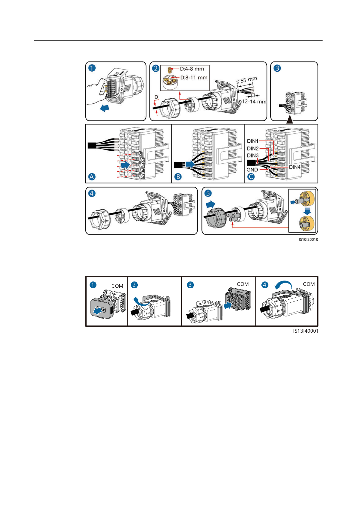
5.7.4 (Optional) Connecting the Power Grid Scheduling Signal Cable
Procedure
Step 1 Connect the signal cable to the signal cable connector.
Issue 03 (2022-08-30) Copyright © Huawei Technologies Co., Ltd. 48
SUN2000-(50KTL-ZHM3, 50KTL-M3)
User Manual 5 Electrical Connections
Figure 5-27 Connecting the cable
Step 2 Connect the signal cable connector to the COM port.
Figure 5-28 Securing the signal cable connector
----End
Issue 03 (2022-08-30) Copyright © Huawei Technologies Co., Ltd. 49

SUN2000-(50KTL-ZHM3, 50KTL-M3)
User Manual 6 Commissioning
6 Commissioning
6.1 Checking Before Power-On
Table 6-1 Checklist
No. Check Item Acceptance Criteria
1 SUN2000 installation The SUN2000 is installed correctly and
securely.
2 Smart Dongle The Smart Dongle is installed correctly
and securely.
3 Cable routing The cables are routed properly as
required by the customer.
4 Cable ties Cable ties are evenly distributed and no
burr exists.
5 Reliable grounding The PE cable is connected correctly and
securely.
6 Switch DC switches and all the switches
connecting to the SUN2000 are OFF.
7 Cable connection The AC output power cable, and DC
input power cables are connected
correctly and securely.
8 Unused terminals and ports Unused terminals and ports are locked
by watertight caps.
9 Installation environment The installation space is proper, and
the installation environment is clean
and tidy.
Issue 03 (2022-08-30) Copyright © Huawei Technologies Co., Ltd. 50

NO TICE
SUN2000-(50KTL-ZHM3, 50KTL-M3)
User Manual 6 Commissioning
6.2 System Power-On
Prerequisites
● Before turning on the AC switch between the SUN2000 and the power grid,
check that the AC voltage is within the
● If the DC power supply is connected but the AC power supply is disconnected,
the SUN2000 will report a Grid Loss alarm. The SUN2000 can start properly
only after the power grid recovers.
Procedure
Step 1 Turn on the AC switch between the SUN2000 and the power grid.
specied range using a multimeter.
Step 2 (Optional) Remove the locking screw beside the DC switch.
Figure 6-1 Removing the locking screw beside the DC switch
Step 3 Turn on the DC switch at the bottom of the SUN2000.
Step 4 Observe the LED indicators to check the operating status of the SUN2000.
Table 6-2 Indicator description
Category
Running
indicator
Status Description
LED1 LED2 –
Steady green Steady green The SUN2000 is
operating in gridtied mode.
Blinking green
slowly (on for 1s
and o for 1s)
Issue 03 (2022-08-30) Copyright © Huawei Technologies Co., Ltd. 51
O The DC is on and
the AC is o.

SUN2000-(50KTL-ZHM3, 50KTL-M3)
User Manual 6 Commissioning
Category Status Description
Communications
indicator
Blinking green
slowly (on for 1s
and o for 1s)
Blinking green
slowly (on for 1s
and o for 1s)
Both the DC and
AC are on, and the
SUN2000 is not
supplying power
to the power grid.
O Blinking green
slowly
The DC is o and
the AC is on.
O O Both the DC and
AC are o.
Blinking red fast
(on for 0.2s and
– DC environment
alarm
o for 0.2s)
– Blinking red fast
(on for 0.2s and
AC environment
alarm
o for 0.2s)
Steady red Steady red Faulty
LED3 –
Blinking green fast (on for 0.2s and
then o for 0.2s)
Communication is
in progress.
Blinking green slowly (on for 1s and o
for 1s)
A mobile phone is
connected.
O No communication
Note: If LED1, LED2, and LED3 are steady red, the SUN2000 is faulty and needs
to be replaced.
----End
Issue 03 (2022-08-30) Copyright © Huawei Technologies Co., Ltd. 52

NO TE
NO TICE
SUN2000-(50KTL-ZHM3, 50KTL-M3)
User Manual 7 Man-Machine Interaction
7 Man-Machine Interaction
● If the SUN2000 is connected to the FusionSolar Smart PV Management System, the
FusionSolar app is recommended. In areas where the FusionSolar app is not available, or
when a third-party management system is used, only the SUN2000 app can be used for
commissioning.
● Access the Huawei app store (http://appstore.huawei.com), search for FusionSolar or
SUN2000, and download the app installation package. You can also scan the QR codes
below to download the apps.
● The screenshots are for reference only. The actual screens may vary.
● Obtain the initial password for connecting to the solar inverter WLAN from the
label on the side of the solar inverter.
● Set the password at the
password periodically and keep the new password in mind. Not changing the
password may cause password disclosure. A password left unchanged for a long
period of time may be stolen or cracked. If a password is lost, devices cannot
be accessed. In these cases, the user is liable for any loss caused to the PV
plant.
● Set the correct grid code based on the application area and scenario of the
SUN2000.
Issue 03 (2022-08-30) Copyright © Huawei Technologies Co., Ltd. 53
rst login. To ensure account security, change the

NO TE
NO TICE
SUN2000-(50KTL-ZHM3, 50KTL-M3)
User Manual 7 Man-Machine Interaction
7.1 Scenario in Which SUN2000s Are Connected to the FusionSolar Smart PV Management System
7.1.1 (Optional) Registering an Installer Account
● If you have an installer account, skip this step.
● You can register an account only using a mobile phone only in China.
● The mobile number or email address used for registration is the user name for logging
in to the FusionSolar app.
Create the
name.
Figure 7-1 Creating the
rst installer account and create a domain named after the company
rst installer account
To create multiple installer accounts for a company, log in to the FusionSolar app
and tap Add User to create an installer account.
Issue 03 (2022-08-30) Copyright © Huawei Technologies Co., Ltd. 54

NO TE
SUN2000-(50KTL-ZHM3, 50KTL-M3)
User Manual 7 Man-Machine Interaction
Figure 7-2 Creating multiple installer accounts for the same company
7.1.2 Creating a PV Plant and a User
Figure 7-3 Creating a PV plant and a user
● In the quick settings for SUN2000-50KTL-M3, the grid code is N/A by default (automatic
startup is not supported). Set the grid code based on the area where the PV plant is
located.
● For details about how to use the site deployment wizard, see
Guide
.
FusionSolar App Quick
7.1.3 SmartLogger Networking Scenario
For details, see
(Inverters + SmartLogger3000), PV Plants Connecting to SmartPVMS Quick
Guide (Inverters + SmartLogger3000 + RS485 Networking)
Issue 03 (2022-08-30) Copyright © Huawei Technologies Co., Ltd. 55
PV Plants Connecting to Huawei Hosting Cloud Quick Guide
and
PV Plants

SUN2000-(50KTL-ZHM3, 50KTL-M3)
User Manual 7 Man-Machine Interaction
Connecting to SmartPVMS Quick Guide (Inverters + SmartLogger3000 +
MBUS Networking)
.
7.2 Scenario in Which SUN2000s Are Connected to Other Management Systems
Step 1 Open the SUN2000 app, scan the QR code of the SUN2000 or manually connect
to the WLAN hotspot to access the device commissioning screen.
Step 2 Select installer and enter the login password.
Step 3 Tap Log in to access the quick settings screen or SUN2000 home screen.
Figure 7-4 Logging In to the app
----End
7.3 Energy Control
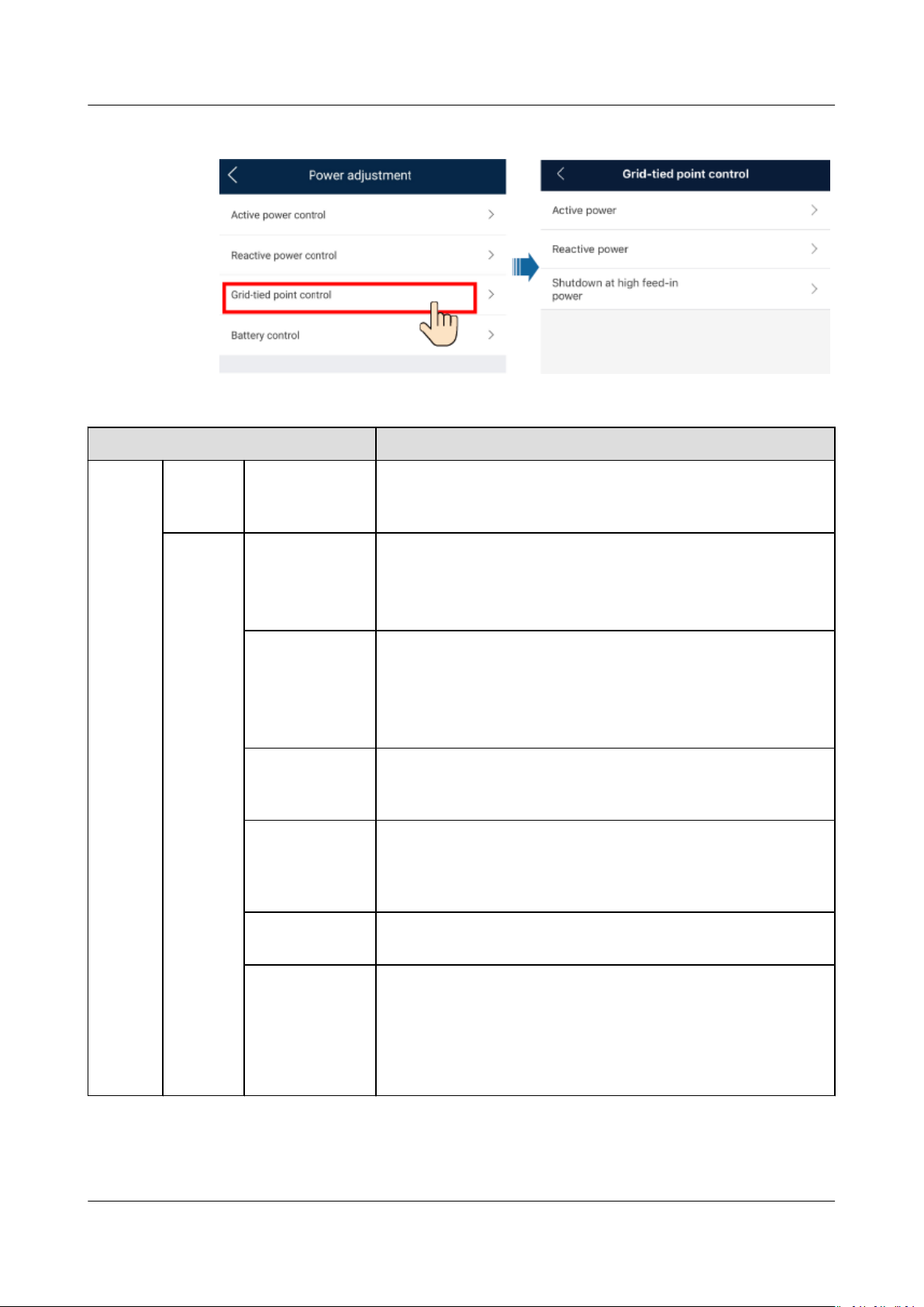
7.3.1 Grid-tied Point Control
Function
Limits or reduces the output power of the PV power system to ensure that the
output power is within the
Procedure
Step 1 On the home screen, choose Power adjustment > Grid-tied point control.
specied range.
Issue 03 (2022-08-30) Copyright © Huawei Technologies Co., Ltd. 56
SUN2000-(50KTL-ZHM3, 50KTL-M3)
User Manual 7 Man-Machine Interaction
Figure 7-5 Grid-tied point control
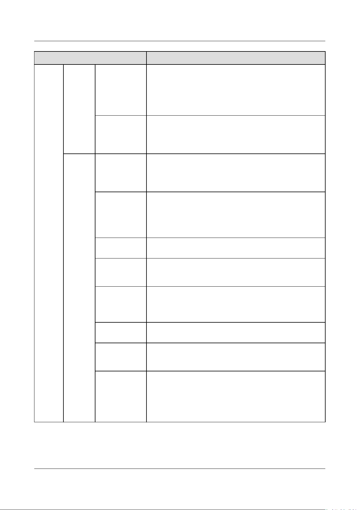
Table 7-1 Grid-tied point control
Parameter Description
Active
power
Unlimited- If this parameter is set to Unlimited, the output power of
the SUN2000 is not limited and the SUN2000 can connect
to the power grid at the rated power.
Grid
connecti
on with
zero
Closed-loop
controller
● If multiple SUN2000s are cascaded, set this parameter
to SDongle/SmartLogger.
● If there is only one SUN2000, set this parameter to
Inverter.
power
Limitation
mode
● Total power indicates export limitation of the total
power at the grid-tied point. (When a single-phase
meter is connected, only Total power can be selected.)
● Single-phase power indicates export limitation of the
power in each phase at the grid-tied point.
Power
adjustment
Species the shortest interval for a single export limitation
adjustment.
period
Maximum
protection time
Species the time for detecting power meter data. If the
Dongle does not detect any power meter data within the
preset time, the Dongle delivers the preset value of Active
power output limit for fail-safe for protection.
Power raising
Species the step for grid-tied power adjustment.
threshold
Active power
output limit for
fail-safe
Species the derating value of the SUN2000 active power
by percentage. If the Smart Dongle does not detect any
meter data or the communication between the Smart
Dongle and the SUN2000 is disconnected, the Smart
Dongle delivers the derating value of the SUN2000 active
power by percentage.
Issue 03 (2022-08-30) Copyright © Huawei Technologies Co., Ltd. 57
SUN2000-(50KTL-ZHM3, 50KTL-M3)
User Manual 7 Man-Machine Interaction
Parameter Description
Grid
connecti
on with
limited
power
(kW)
Communicatio
n
disconnection
fail-safe
Communicatio
n
disconnection
detection time
Closed-loop
controller
Limitation
mode
Maximum grid
feed-in power
In the inverter export limitation scenario, if this parameter
is set to Enable, the inverter will derate according to the
active power derating percentage when the
communication between the inverter and the Smart
Dongle is disconnected for a period longer than
Communication disconnection detection time.
Species the fail-safe detection time for the disconnection
between the SUN2000 and the Smart Dongle.
This parameter is displayed when Communication
disconnection fail-safe is enabled.
● If multiple SUN2000s are cascaded, set this parameter
to SDongle/SmartLogger.
● If there is only one SUN2000, set this parameter to
Inverter.
Total power indicates export limitation of the total power
at the grid-tied point. (When a single-phase meter is
connected, only Total power can be selected.)
Single-phase power indicates export limitation of the
power in each phase at the grid-tied point.
Species the maximum active power transmitted from the
grid-tied point to the power grid.
Power
adjustment
period
Maximum
protection time
Power raising
threshold
Power
adjustment
period
Active power
output limit for
fail-safe
Species the shortest interval for a single export limitation
adjustment.
Species the time for detecting power meter data. If the
Dongle does not detect any power meter data within the
preset time, the Dongle delivers the preset value of Active
power output limit for fail-safe for protection.
Species the step for grid-tied power adjustment.
Species the shortest interval for a single export limitation
adjustment.
Species the derating value of the inverter active power by
percentage. If the Smart Dongle does not detect any power
meter data or the communication between the Smart
Dongle and the inverter is disconnected, the Smart Dongle
delivers the derating value of the inverter active power by
percentage.
Issue 03 (2022-08-30) Copyright © Huawei Technologies Co., Ltd. 58
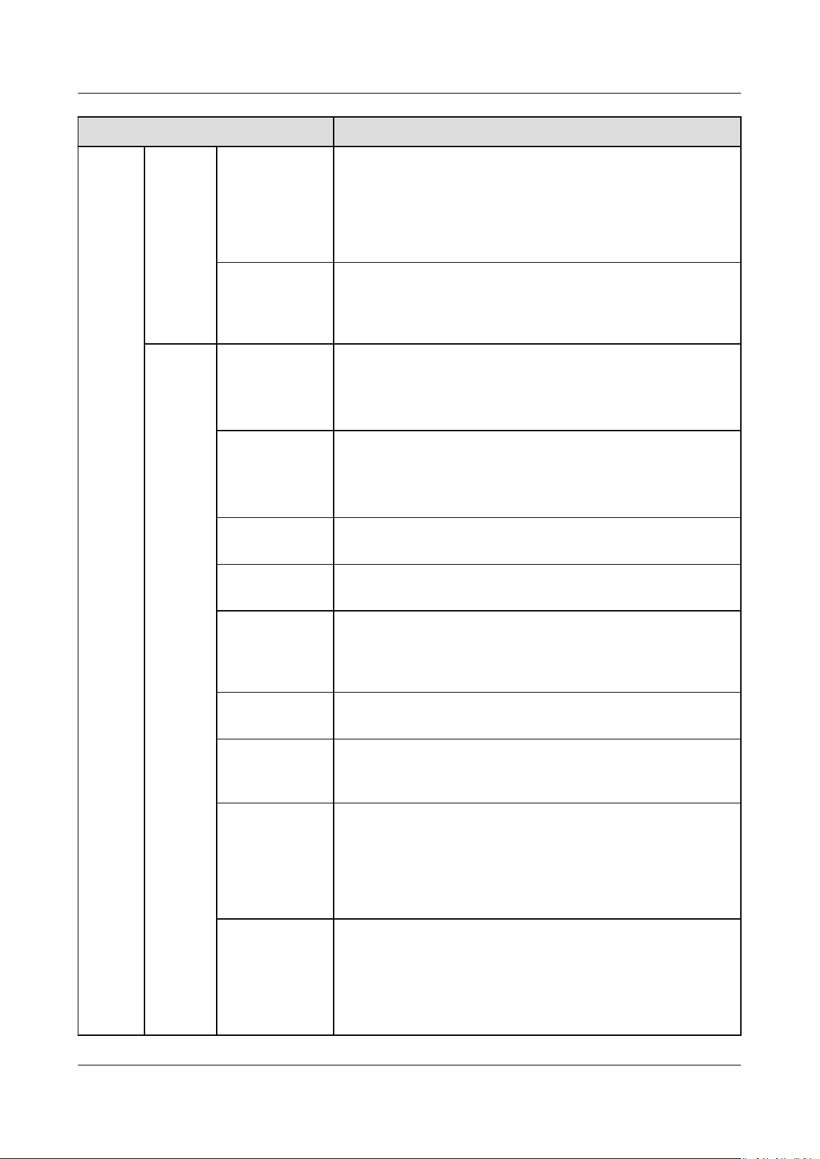
SUN2000-(50KTL-ZHM3, 50KTL-M3)
User Manual 7 Man-Machine Interaction
Parameter Description
Grid
connecti
on with
limited
power
(%)
Communicatio
n
disconnection
fail-safe
Communicatio
n
disconnection
detection time
Closed-loop
controller
Limitation
mode
PV plant
capacity
In the inverter export limitation scenario, if this parameter
is set to Enable, the inverter will derate according to the
active power derating percentage when the
communication between the inverter and the Smart
Dongle is disconnected for a period longer than
Communication disconnection detection time.
Species the time for determining the communication
disconnection between the inverter and the Smart Dongle.
This parameter is displayed when Communication
disconnection fail-safe is set to Enable.
● For a single inverter, set Closed-loop controller to
Inverter.
● For multiple inverters, Closed-loop controller can only
be set to SDongle/SmartLogger.
● Total power indicates export limitation of the total
power at the grid-tied point.
● Single-phase power indicates export limitation of the
power in each phase at the grid-tied point.
Species the total maximum active power in the inverter
cascading scenario.
Maximum grid
feed-in power
Maximum
protection time
Power raising
threshold
Power
adjustment
period
Active power
output limit for
fail-safe
Communicatio
n
disconnection
fail-safe
Species the percentage of the maximum active power of
the grid-tied point to the PV plant capacity.
Species the time for detecting power meter data. If the
Dongle does not detect any power meter data within the
preset time, the Dongle delivers the preset value of Active
power output limit for fail-safe for protection.
Species the step for grid-tied power adjustment.
Species the shortest interval for a single export limitation
adjustment.
Species the derating value of the inverter active power by
percentage. If the Smart Dongle does not detect any power
meter data or the communication between the Smart
Dongle and the inverter is disconnected, the Smart Dongle
delivers the derating value of the inverter active power by
percentage.
In the inverter export limitation scenario, if this parameter
is set to Enable, the inverter will derate according to the
active power derating percentage when the
communication between the inverter and the Smart
Dongle is disconnected for a period longer than
Communication disconnection detection time.
Issue 03 (2022-08-30) Copyright © Huawei Technologies Co., Ltd. 59
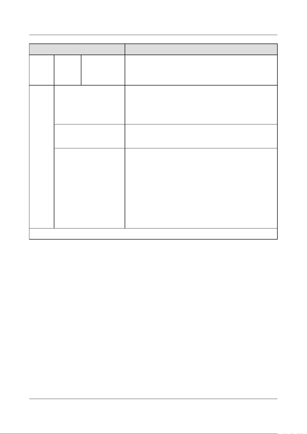
SUN2000-(50KTL-ZHM3, 50KTL-M3)
User Manual 7 Man-Machine Interaction
Parameter Description
Shutdo
wn at
high
feed-in
power
Communicatio
n
disconnection
detection time
Shutdown at high feed-in
power
1
Upper feed-in power
threshold for inverter
shutdown (kW)
High feed-in power
duration threshold for
triggering inverter
shutdown (s)
Species the time for determining the communication
disconnection between the inverter and the Smart Dongle.
This parameter is displayed when Communication
disconnection fail-safe is set to Enable.
● The default value is Disable.
● If this parameter is set to Enable, the inverter shuts
down for protection when the grid-connection point
power exceeds the threshold and remains in this
condition for the specied time threshold.
The default value is 0. This parameter species the power
threshold of the grid-connection point for triggering
inverter shutdown.
The default value is 20. This parameter species the
duration threshold of high feed-in power for triggering
inverter shutdown.
● When High feed-in power duration threshold for
triggering inverter shutdown is set to 5. Shutdown at
high feed-in power takes precedence.
● When High feed-in power duration threshold for
triggering inverter shutdown is set to 20, Grid
connection with limited power takes precedence
(when Active power control is set to Grid connection
with limited power).
Note 1: This parameter is supported only for the AS4777 grid code.
----End
7.3.2 Apparent Power Control on the Inverter Output Side
On the home screen, tap Settings > Power adjustment to set inverter
parameters.
Issue 03 (2022-08-30) Copyright © Huawei Technologies Co., Ltd. 60
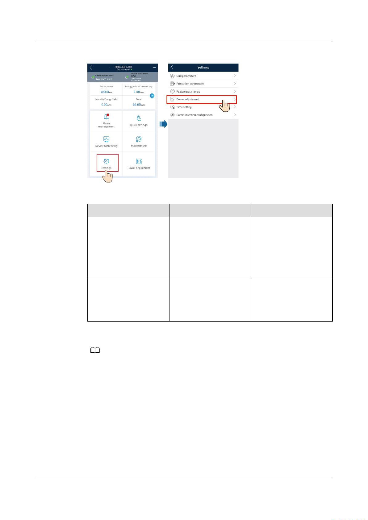
NO TE
SUN2000-(50KTL-ZHM3, 50KTL-M3)
User Manual 7 Man-Machine Interaction
Figure 7-6 Apparent power control
Table 7-2 Apparent power
Parameter Description Value Range
Maximum apparent
power (kVA)
Species the output
upper threshold for the
[Maximum active power,
S
]
max
maximum apparent
power to adapt to the
capacity requirements of
standard and customized
inverters.
Maximum active power
(kW)
Species the output
upper threshold for the
[0.1, P
max
]
maximum active power
to adapt to dierent
market requirements.
The lower threshold for the maximum apparent power is the maximum active power. To
lower the maximum apparent power, lower the maximum active power rst.
Issue 03 (2022-08-30) Copyright © Huawei Technologies Co., Ltd. 61
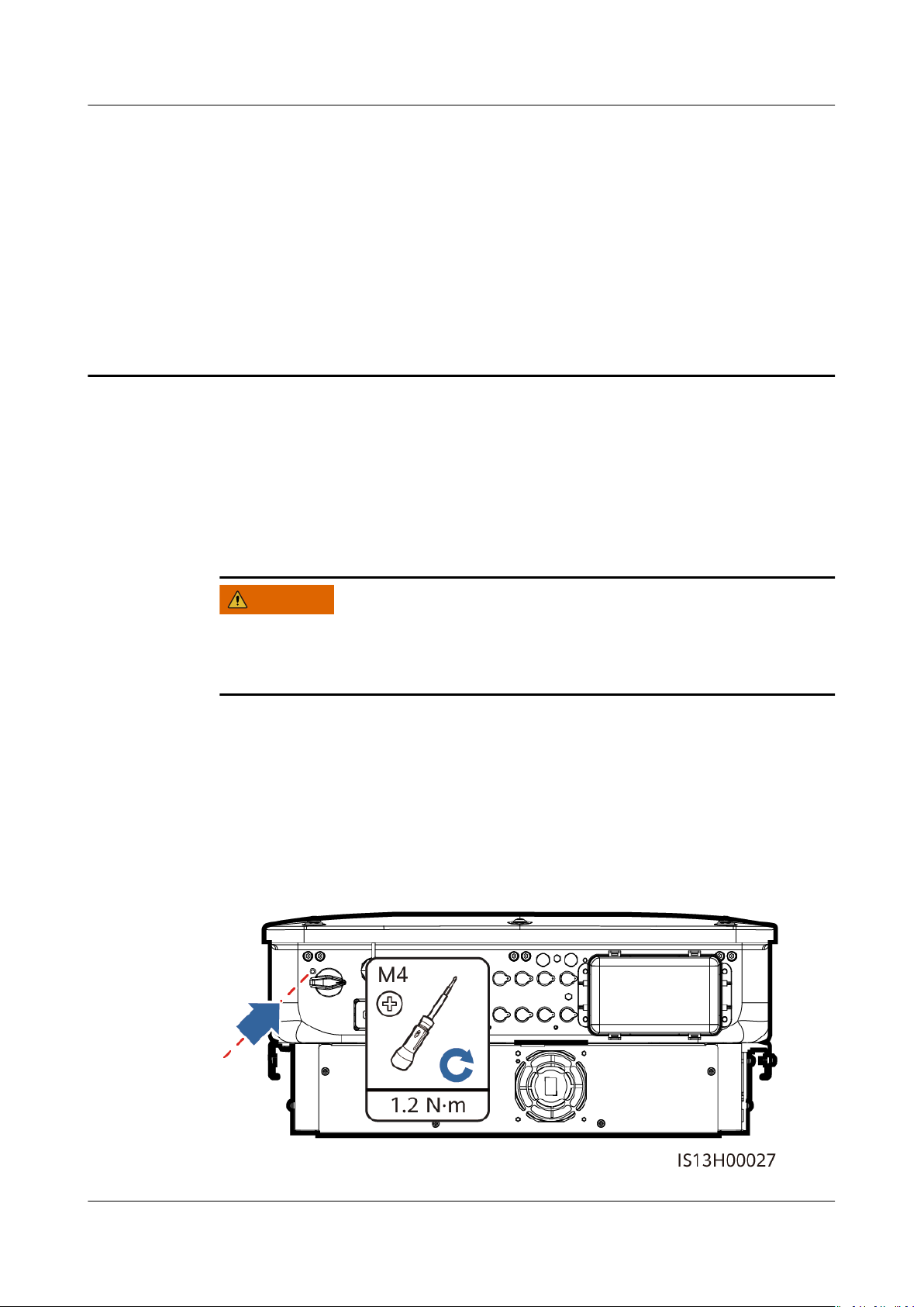
WARNING
SUN2000-(50KTL-ZHM3, 50KTL-M3)
User Manual 8 Maintenance
8 Maintenance
8.1 System Power-O
Precautions
Procedure
Step 1 Send a shutdown command on the app.
Step 2 Turn
Step 3 Turn o the DC switch at the bottom of the SUN2000.
Step 4 (Optional) Install the locking screw for the DC switch.
After the SUN2000 powers o, the remaining electricity and heat may still cause
electric shocks and body burns. Therefore, put on protective gloves and begin
operating the SUN2000
o the AC switch between the SUN2000 and the power grid.
Figure 8-1 Installing the locking screw for the DC switch
ve minutes after the power-o.
Issue 03 (2022-08-30) Copyright © Huawei Technologies Co., Ltd. 62
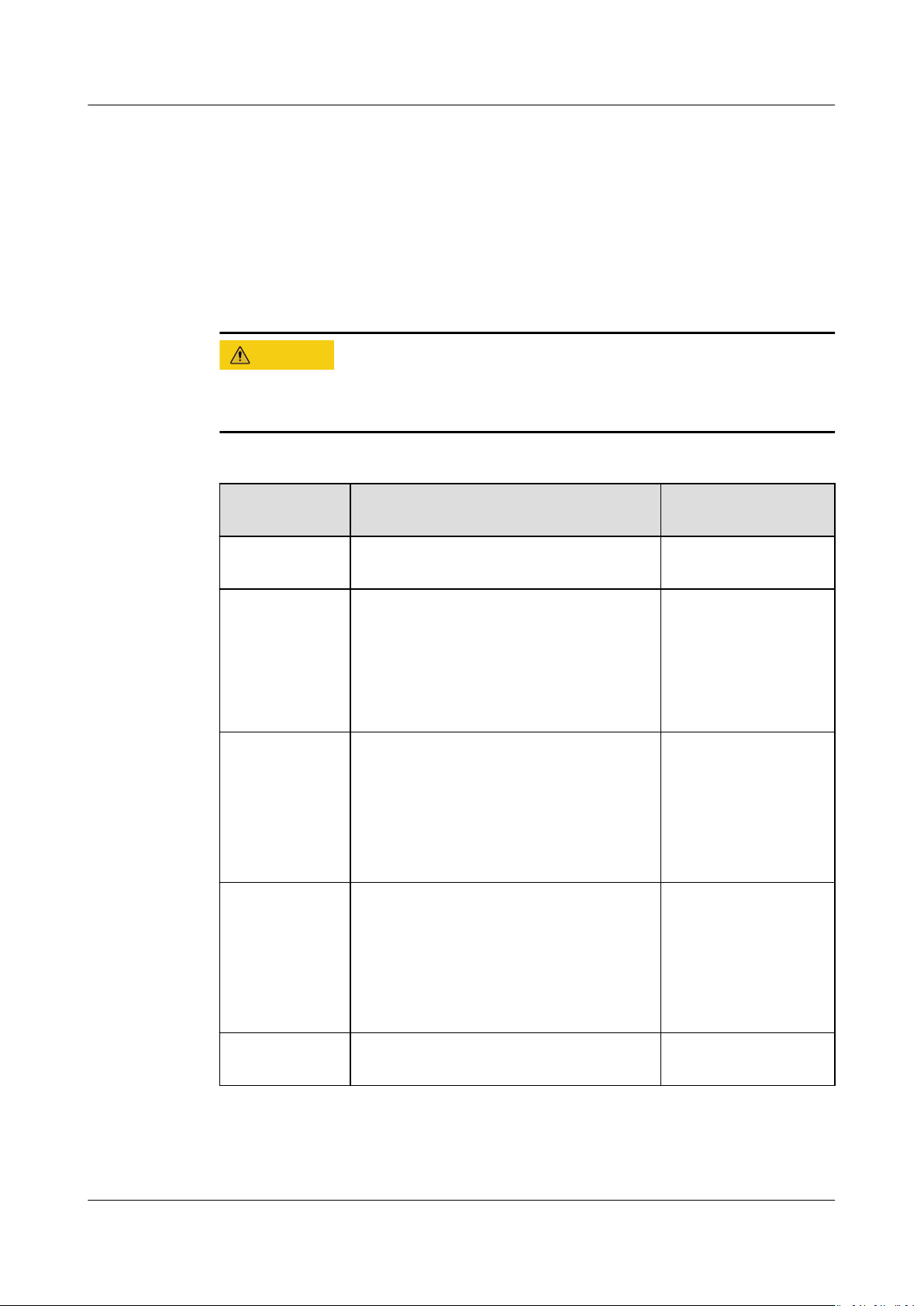
CA UTION
SUN2000-(50KTL-ZHM3, 50KTL-M3)
User Manual 8 Maintenance
Step 5 Turn on the DC switch between the PV string and the SUN2000 if there is any.
----End
8.2 Routine Maintenance
To ensure that the SUN2000 can operate properly for a long term, you are advised
to perform routine maintenance on it as described in this chapter.
Before cleaning the system, connecting cables, and ensuring the grounding
reliability, power o the system.
Table 8-1 Maintenance checklist
Check Item Check Method Maintenance
Interval
System
cleanliness
System
operating
status
Electrical
connection
Grounding
reliability
Check periodically that the heat sinks
are free from obstacles and dust.
● Check that the SUN2000 is not
damaged or deformed.
● Check that the SUN2000 operates
with no abnormal sound.
● Check that all SUN2000 parameters
are correctly set during operation.
● Check that cables are secured.
● Check that cables are intact, and
that in particular, the parts touching
the metallic surface are not
scratched.
Check that ground cables are securely
connected.
Once every 6 to 12
months
Once every 6
months
The rst inspection is
6 months after the
initial
commissioning.
From then on, the
interval can be 6 to
12 months.
The rst inspection is
6 months after the
initial
commissioning.
From then on, the
interval can be 6 to
12 months.
Issue 03 (2022-08-30) Copyright © Huawei Technologies Co., Ltd. 63
Air tightness Check that all terminals and ports are
properly sealed.
Once a year
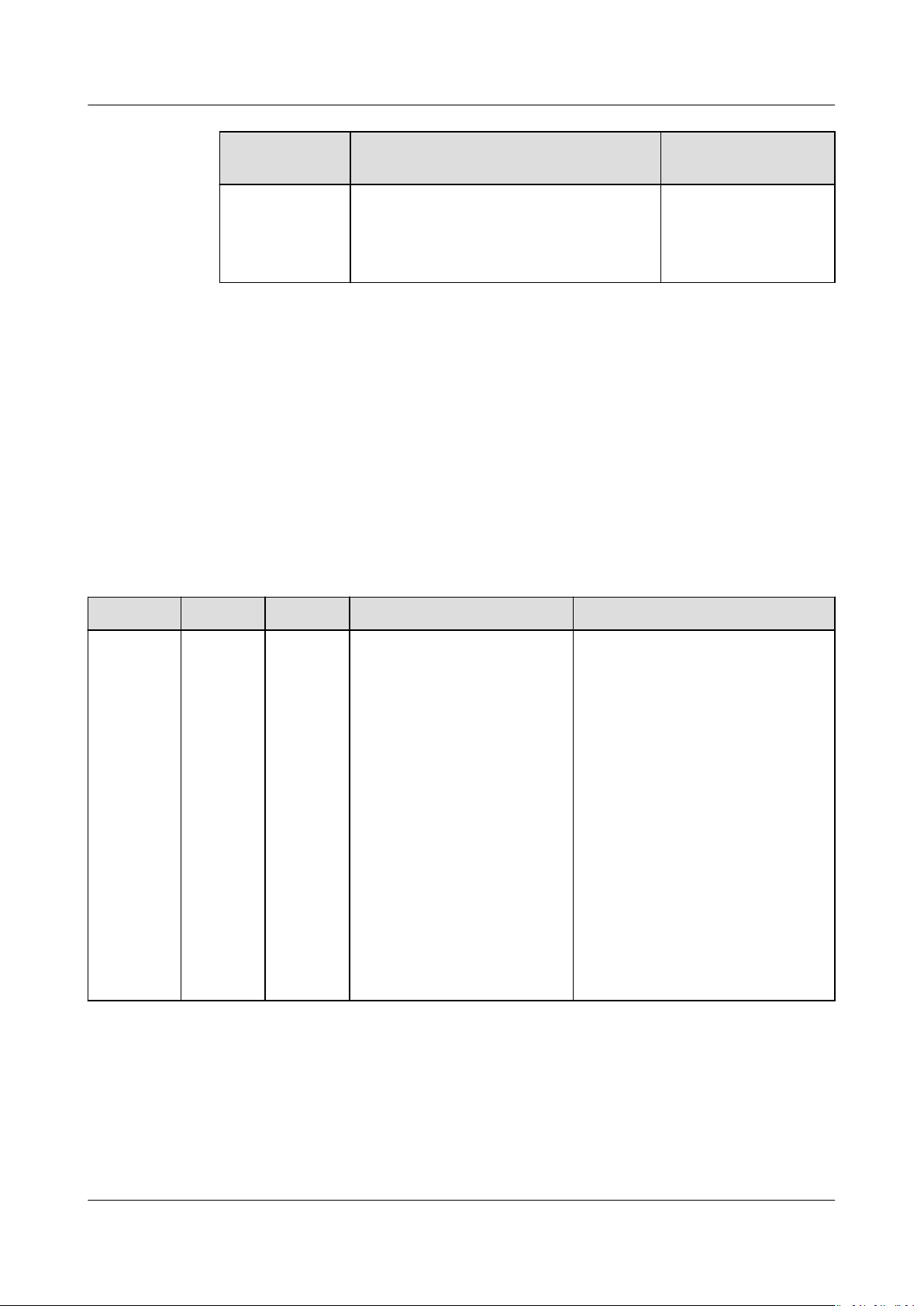
SUN2000-(50KTL-ZHM3, 50KTL-M3)
User Manual 8 Maintenance
Check Item Check Method Maintenance
Interval
Clear
vegetation
around the
inverters
8.3 Troubleshooting
Alarm severities are dened as follows:
● Major: The inverter is faulty. As a result, the output power decreases or the
grid-tied power generation is stopped.
● Minor: Some components are faulty without
generation.
● Warning: The inverter works properly. The output power decreases or some
authorization functions fail due to external factors.
Table 8-2 Common fault alarm list
ID
2001 High
Name Severity Cause Solution
Major The PV array is not
string
input
voltage
● Perform inspection and weeding as
required.
● Clean the site promptly after
weeding.
aecting the grid-tied power
Reduce the number of PV
properly congured.
Excessive PV modules are
connected in series to the
PV string, and therefore the
PV string open-circuit
voltage exceeds the
maximum inverter
operating voltage.
● Cause ID 1: PV strings 1
and 2
● Cause ID 2: PV strings 3
and 4
● Cause ID 3: PV strings 5
and 6
● Cause ID 4: PV strings 7
and 8
modules connected in series to
the PV string until the PV string
open-circuit voltage is less than
or equal to the maximum
inverter operating voltage. After
the PV string
corrected, the alarm disappears.
Based on the local
wilting season
conguration is
Issue 03 (2022-08-30) Copyright © Huawei Technologies Co., Ltd. 64
SUN2000-(50KTL-ZHM3, 50KTL-M3)
User Manual 8 Maintenance
ID Name Severity Cause Solution
2002 DC arc
fault
2003 DC arc
fault
2011 String
reverse
connecti
on
Major The PV string power cables
arc or are in poor contact.
● Cause ID 1: PV strings 1
and 2
● Cause ID 2: PV strings 3
and 4
● Cause ID 3: PV strings 5
and 6
● Cause ID 4: PV strings 7
and 8
Major The PV string power cables
arc or are in poor contact.
Cause ID 1–8: PV strings 1–
8
Major The PV string polarity is
reversed.
Cause ID 1–8: PV strings 1–
8
Check whether the PV string
cables arc or are in poor contact.
Check whether the PV string
cables arc or are in poor contact.
1. Check whether the PV string
is connected to the device in
reverse polarity. If yes, wait
until the PV string current
decreases to below 0.5 A, set
DC SWITCH to OFF, and
adjust the PV string polarity.
2. If the fault persists, reset the
device on the local
maintenance app or WebUI
of the upper-layer controller.
Alternatively, you can turn
o
the AC and DC switches, wait
for 5 minutes, and then turn
on the AC and DC switches.
2012 String
current
backfeed
Warning The number of PV modules
connected in series to the
PV string is insucient. As
a result, the terminal
voltage is lower than that
of other strings.
Cause ID 1–8: PV strings 1–
8
1. Check whether the number of
PV modules connected in
series to the PV string is less
than that of other PV strings.
If yes, wait until the PV string
current drops below 0.5 A,
o all DC switches, and
turn
adjust the number of PV
modules in the PV string.
2. Check whether the opencircuit voltage of the PV
string is abnormal.
3. Check whether the PV string
is shaded.
Issue 03 (2022-08-30) Copyright © Huawei Technologies Co., Ltd. 65

SUN2000-(50KTL-ZHM3, 50KTL-M3)
User Manual 8 Maintenance
ID Name Severity Cause Solution
2021 AFCI
self-
Major Cause ID = 1, 2
The AFCI self-check fails.
check
failure
2031 Phase
wire
shortcircuited
to PE
Major Cause ID = 1
The impedance of the
output phase wire to PE is
low or the output phase
wire is short-circuited to PE.
2032 Grid loss Major Cause ID = 1
● Power grid outage
occurs.
● The AC circuit is
disconnected or the AC
switch is
2033 Grid
undervol
tage
Major Cause ID = 1
The power grid voltage is
below the lower threshold
or the low-voltage duration
has lasted for more than
the value
specied by LVRT.
o.
Turn o the AC output switch
and DC input switch, and then
turn them on after 5 minutes. If
the alarm persists, contact
Huawei technical support.
Check the impedance of the
output phase wire to PE, locate
the position with low
impedance, and rectify the fault.
1. The alarm is cleared
automatically after the power
grid recovers.
2. Check whether the AC circuit
is disconnected or the AC
switch is
o.
1. If the alarm occurs
occasionally, the power grid
may be abnormal
temporarily. The inverter
automatically recovers after
detecting that the power grid
becomes normal.
2. If the alarm persists, check
whether the power grid
voltage is within the
acceptable range. If not,
contact the local power
operator. If yes, modify the
grid undervoltage protection
threshold through the app,
SmartLogger, or NMS with
the consent of the local
power operator.
3. If the alarm persists for a
long time, check the AC
circuit breaker and AC output
power cable.
Issue 03 (2022-08-30) Copyright © Huawei Technologies Co., Ltd. 66

SUN2000-(50KTL-ZHM3, 50KTL-M3)
User Manual 8 Maintenance
ID Name Severity Cause Solution
2034 Grid
overvolt
age
Major Cause ID = 1
The power grid voltage
exceeds the upper
threshold or the high
voltage duration has lasted
for more than the value
specied by HVRT.
1. If the alarm occurs
occasionally, the power grid
may be abnormal
temporarily. The device
automatically recovers after
detecting that the power grid
becomes normal.
2. If the alarm occurs frequently,
check whether the power grid
voltage is within the allowed
range. If not, contact the
local power operator. If yes,
modify the power grid
overvoltage protection
threshold after obtaining the
consent of the local power
operator.
3. Check whether the peak
voltage of the power grid is
too high. If the fault occurs
frequently and persists for a
long time, contact the local
power operator.
2035
Grid
volt.
Imbalan
ce
Major Cause ID = 1
The dierence between
power grid phase voltages
exceeds the upper
threshold.
1. If the alarm occurs
occasionally, the power grid
may be abnormal
temporarily. The inverter
automatically recovers after
detecting that the power grid
becomes normal.
2. If the alarm persists, check
whether the power grid
voltage is within the
acceptable range. If not,
contact the local power
operator.
3. If the alarm lasts for a long
time, check the AC output
power cable connection.
4. If the AC output power cable
is correctly connected, yet the
alarm persists and
aects the
energy yield of the PV plant,
contact the local power
operator.
Issue 03 (2022-08-30) Copyright © Huawei Technologies Co., Ltd. 67

SUN2000-(50KTL-ZHM3, 50KTL-M3)
User Manual 8 Maintenance
ID Name Severity Cause Solution
2036 Grid
overfreq
uency
2037 Grid
underfre
quency
Major Cause ID = 1
Power grid exception: The
actual power grid
frequency is higher than
the requirements for the
local power grid code.
Major Cause ID = 1
Power grid exception: The
actual power grid
frequency is lower than the
requirements for the local
power grid code.
1. If the alarm occurs
occasionally, the power grid
may be abnormal
temporarily. The inverter
automatically recovers after
detecting that the power grid
becomes normal.
2. If the alarm persists, check
whether the power grid
frequency is within the
acceptable range. If not,
contact the local power
operator. If yes, modify the
grid overfrequency protection
threshold through the app,
SmartLogger, or NMS with
the consent of the local
power operator.
1. If the alarm occurs
occasionally, the power grid
may be abnormal
temporarily. The inverter
automatically recovers after
detecting that the power grid
becomes normal.
2. If the alarm persists, check
whether the power grid
frequency is within the
acceptable range. If not,
contact the local power
operator. If yes, modify the
grid underfrequency
protection threshold through
the app, SmartLogger, or
NMS with the consent of the
local power operator.
Issue 03 (2022-08-30) Copyright © Huawei Technologies Co., Ltd. 68

SUN2000-(50KTL-ZHM3, 50KTL-M3)
User Manual 8 Maintenance
ID Name Severity Cause Solution
2038 Unstable
grid
frequenc
y
2039 Output
overcurr
ent
Major Cause ID = 1
Power grid exception: The
actual change rate of the
power grid frequency does
not meet the requirements
for the local power grid
code.
Major Cause ID = 1
The power grid voltage
drops dramatically or the
power grid is shortcircuited. As a result, the
inverter transient output
current exceeds the upper
threshold, and protection is
triggered.
1. If the alarm occurs
occasionally, the power grid
may be abnormal
temporarily. The inverter
automatically recovers after
detecting that the power grid
becomes normal.
2. If the alarm persists, check
whether the power grid
frequency is within the
acceptable range. If not,
contact the local power
operator.
1. The inverter monitors its
external operating conditions
in real time and
automatically recovers after
the fault is rectied.
2. If the alarm persists and
aects the energy yield of the
PV plant, check whether the
output is short-circuited. If
the fault cannot be
rectied,
contact your dealer or
Huawei technical support.
2040 Output
DC
compon
ent
overhigh
2051 Abnorm
al
residual
current
Major Cause ID = 1
The DC component of the
inverter output current
exceeds the upper
threshold.
Major Cause ID = 1
The insulation impedance
of the input side to PE
decreases when the
inverter is operating.
1. The inverter monitors its
external operating conditions
in real time and
automatically recovers after
the fault is rectied.
2. If the alarm persists and
aects the energy yield of the
PV plant, contact your dealer
or Huawei technical support.
1. If the alarm occurs
accidentally, the external
power cable may be
abnormal temporarily. The
inverter automatically
recovers after the fault is
rectied.
2. If the alarm persists or lasts a
long time, check whether the
impedance between the PV
string and ground is too low.
Issue 03 (2022-08-30) Copyright © Huawei Technologies Co., Ltd. 69

SUN2000-(50KTL-ZHM3, 50KTL-M3)
User Manual 8 Maintenance
ID Name Severity Cause Solution
2061 Abnorm
al
groundin
g
Major Cause ID = 1
● The neutral wire or PE
cable of the inverter is
not connected.
● The output mode set for
the inverter is
inconsistent with the
cable connection mode.
Power o the inverter (turn o
the AC output switch and DC
input switch, and wait for a
period of time. For details about
the wait time, see the
description on the device safety
warning label), and then
perform the following
operations:
1. Check whether the PE cable
for the inverter is connected
properly.
2. If the inverter is connected to
a TN power grid, check
whether the neutral wire is
properly connected and
whether the voltage of the
neutral wire to ground is
normal.
3. After the inverter is powered
on, check whether the output
mode set for the inverter is
consistent with the output
cable connection mode.
2062
Low
insulatio
n
resistanc
e
Major Cause ID = 1
● The PV array is shortcircuited with PE.
● The PV string has been
in a moist environment
for a long time and the
circuit is not well
insulated to ground.
1. Check the impedance
between the PV string and
the PE cable. If a short circuit
occurs, rectify the fault.
2. Check whether the PE cable
of the inverter is correctly
connected.
3. If you have
conrmed that
the impedance is lower than
specied protection
the
threshold in a cloudy or rainy
environment, log in to the
app, SmartLogger, or NMS
and set Insulation resistance
protection threshold.
Issue 03 (2022-08-30) Copyright © Huawei Technologies Co., Ltd. 70

SUN2000-(50KTL-ZHM3, 50KTL-M3)
User Manual 8 Maintenance
ID Name Severity Cause Solution
2063 Cabinet
overtem
perature
2064 Device
fault
Minor Cause ID = 1
● The inverter is installed
in a place with poor
ventilation.
● The ambient
temperature exceeds the
upper threshold.
● The inverter is not
operating properly.
Major Cause ID = 1–15
An unrecoverable fault
occurs on a circuit inside
the inverter.
1. Check the ventilation and
ambient temperature at the
inverter installation position.
2. If the ventilation is poor or
the ambient temperature
exceeds the upper threshold,
improve the ventilation and
heat dissipation.
3. If both the ventilation and
ambient temperature meet
requirements yet the alarm
persists, contact your dealer
or Huawei technical support.
Turn o the AC output switch
and DC input switch, and then
turn them on after 5 minutes. If
the alarm persists, contact your
dealer or Huawei technical
support.
NOTICE
Cause ID = 1: Perform the preceding
operations when the PV string
current is less than 1 A.
2065 Upgrade
failed or
version
mismatc
h
2066 License
expired
Minor Cause ID = 1–6
The upgrade is not
completed normally.
Warning Cause ID = 1
● The privilege license has
entered the grace
period.
● The privilege feature is
about to expire.
1. Perform an upgrade again.
2. If the upgrade fails several
times, contact your dealer or
Huawei technical support.
1. Apply for a new license.
2. Load a new certicate.
Issue 03 (2022-08-30) Copyright © Huawei Technologies Co., Ltd. 71

SUN2000-(50KTL-ZHM3, 50KTL-M3)
User Manual 8 Maintenance
ID Name Severity Cause Solution
2067 Faulty
power
collector
61440 Faulty
monitori
ng unit
Major Cause ID = 1
The power meter is
disconnected.
Minor Cause ID = 1
● The ash memory is
insucient.
● The ash memory has
bad sectors.
1. Check whether the
congured power meter
model is the same as the
actual model.
2. Check whether the
communications parameters
of the power meter are the
same as the RS485
congurations of the inverter.
3. Check whether the power
meter is powered on and
whether the RS485
communications cable is
connected.
Turn o the AC output switch
and DC input switch, and then
turn them on after 5 minutes. If
the alarm persists, replace the
monitoring board or contact
your dealer or Huawei technical
support.
2072 Transient
AC
overvolt
age
Major Cause ID = 1
The inverter detects that
the phase voltage exceeds
the transient AC
overvoltage protection
threshold.
1. If the voltage at the grid
connection point is too high,
contact the local power
operator.
2. If you have conrmed that
the voltage at the grid
connection point exceeds the
upper threshold and obtained
consent from the local power
operator, modify the
overvoltage protection
thresholds.
3. Check whether the peak grid
voltage exceeds the upper
threshold.
Issue 03 (2022-08-30) Copyright © Huawei Technologies Co., Ltd. 72
SUN2000-(50KTL-ZHM3, 50KTL-M3)
User Manual 8 Maintenance
ID Name Severity Cause Solution
2085 Built-in
PID
operatio
n
abnorma
l
Minor Cause ID = 1, 2
● The output resistance of
PV arrays to ground is
low.
● The system insulation
resistance is low.
● Cause ID = 1
1. Turn o the AC output
switch and DC input
switch, wait for a period of
time (for details about the
wait time, see the
description on the device
safety warning label), and
then turn on the DC input
switch and AC output
switch.
2. If the alarm persists,
contact your dealer or
Huawei technical support.
● Cause ID = 2
1. Check the impedance
between the PV array
output and the ground. If
a short circuit occurs or
the insulation is
insucient, rectify the
fault.
2. If the alarm persists,
contact your dealer or
Huawei technical support.
2086
External
fan
abnorma
l
Major Cause ID = 1
The external fan is shortcircuited, the power supply
is insucient, or the air
channel is blocked.
1. Shut down the fan, turn o
the DC switch, check whether
the fan blades are damaged,
and clear the foreign matter
around the fan.
2. Reinstall the fan, turn on the
DC switch, and wait for the
inverter to start. If the alarm
persists after 15 minutes,
replace the external fan.
Issue 03 (2022-08-30) Copyright © Huawei Technologies Co., Ltd. 73
NO TE
CA UTION
SUN2000-(50KTL-ZHM3, 50KTL-M3)
User Manual 8 Maintenance
ID Name Severity Cause Solution
2090 Abnorm
al active
power
scheduli
ng
instructi
on
2091 Abnorm
al
reactive
power
scheduli
ng
instructi
on
Major Cause ID = 1
● The DI input is
abnormal.
● The DI input is
inconsistent with the
conguration.
Major Cause ID = 1
● The DI input is
abnormal.
● The DI input is
inconsistent with the
conguration.
1. Check whether the cables are
connected correctly to the DI
ports.
2. On the DI active scheduling
screen under the dry contact
scheduling settings, view the
DI signal
mapping table. Contact the
power grid company to check
whether the
the mapping table are
complete and meet the
requirements.
1. Check whether the cables are
connected correctly to the DI
ports.
2. On the DI reactive power
scheduling screen under the
dry contact scheduling
settings, view the DI signal
conguration mapping table.
Contact the power grid
company to check whether
the
mapping table are complete
and meet the requirements.
conguration
congurations in
congurations in the
Contact your dealer or Huawei technical support if all troubleshooting procedures listed
above are completed and the fault still exists.
8.4 Replacing a Fan
● Before replacing a fan, power o the inverter.
● When replacing a fan, use insulated tools and wear PPE.
Step 1 Remove the screws from the fan mounting plate and store them properly. Turn the
fan mounting plate until the fan surface is horizontal with the inverter.
Issue 03 (2022-08-30) Copyright © Huawei Technologies Co., Ltd. 74

NO TICE
SUN2000-(50KTL-ZHM3, 50KTL-M3)
User Manual 8 Maintenance
Figure 8-2 Removing screws from the fan mounting plate
Step 2 Remove the cable tie, loosen the connector, disconnect the cable, and remove the
faulty fan.
Figure 8-3 Removing a faulty fan
Step 3 Install the new fan in the reverse order, bind the fan cable, and reconnect the
cable.
When binding the cable, you are advised to reserve 80 mm at one end of the
terminal, fold the rest of the cable and bind it in the middle using a cable tie, and
then bind the cable to the cable bridge.
Issue 03 (2022-08-30) Copyright © Huawei Technologies Co., Ltd. 75
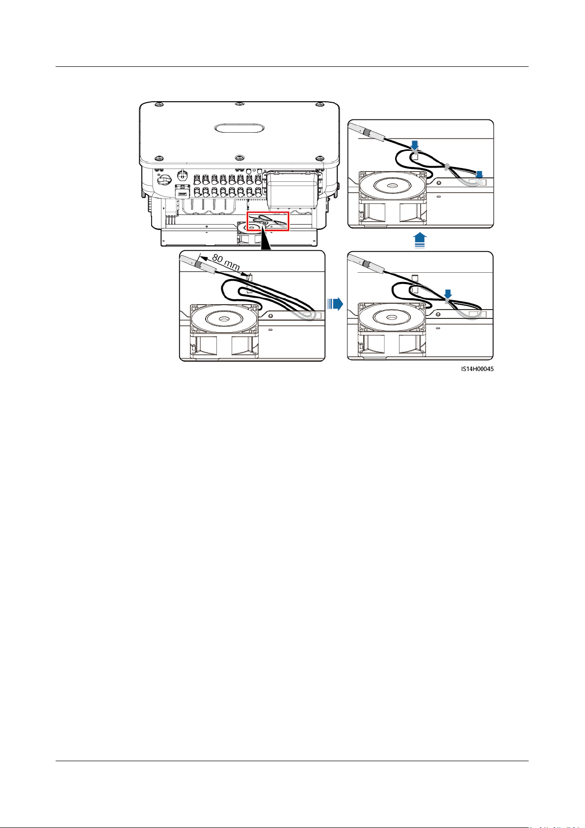
SUN2000-(50KTL-ZHM3, 50KTL-M3)
User Manual 8 Maintenance
Figure 8-4 Binding a cable
----End
Issue 03 (2022-08-30) Copyright © Huawei Technologies Co., Ltd. 76
NO TICE
SUN2000-(50KTL-ZHM3, 50KTL-M3)
User Manual 9 Handling the Inverter
9 Handling the Inverter
9.1 Removing the SUN2000
Before removing the SUN2000, disconnect both AC and DC connections.
Perform the following operations to remove the SUN2000:
1. Disconnect all cables from the SUN2000, including RS485 communications
cables, DC input power cables, AC output power cables, and PGND cables.
2. Remove the SUN2000 from the mounting bracket.
3. Remove the mounting bracket.
9.2 Packing the SUN2000
● If the original packing materials are available, put the SUN2000 inside them
and then seal them by using adhesive tape.
● If the original packing materials are not available, put the SUN2000 inside a
suitable cardboard box and seal it properly.
9.3 Disposing of the SUN2000
If the SUN2000 service life expires, dispose of it according to the local disposal
rules for electrical equipment waste.
Issue 03 (2022-08-30) Copyright © Huawei Technologies Co., Ltd. 77
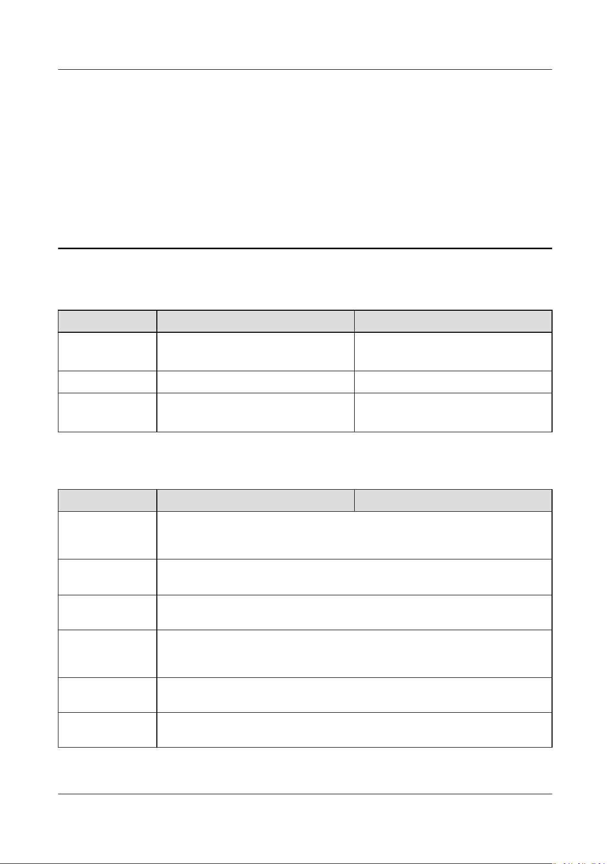
SUN2000-(50KTL-ZHM3, 50KTL-M3)
User Manual 10 Technical Specications
10 Technical Specications
Eciency
Item SUN2000-50KTL-ZHM3 SUN2000-50KTL-M3
Peak eciency 98.50% 98.50%/400 V
98.71%/480 V
Chinese eciency 98.00% -
European
eciency
- 98.24%/400 V
Input
Item
Recommended
maximum input
DC power
Maximum input
voltage
Maximum input
current per string
Maximum shortcircuit current per
MPPT
a
SUN2000-50KTL-ZHM3 SUN2000-50KTL-M3
75000 W
1100 V
20 A (one PV string)/30 A (one MPPT)
40 A
98.40%/480 V
Minimum startup
voltage
MPP voltage
range
Issue 03 (2022-08-30) Copyright © Huawei Technologies Co., Ltd. 78
200 V
200–1000 V

SUN2000-(50KTL-ZHM3, 50KTL-M3)
User Manual 10 Technical Specications
Item SUN2000-50KTL-ZHM3 SUN2000-50KTL-M3
Full-load MPPT
voltage range
Rated input
voltage
Maximum
b
530–800 V (380 V AC/400 V AC) 530–800 V (380 V AC/400 V AC)
625–850 V (480 V AC)
600 V (380 V AC/400 V AC) 600 V (380 V AC/400 V AC)
710 V (480 V AC)
8
number of inputs
Number of
4
MPPTs
Note a: The maximum input voltage is the maximum DC input voltage that the inverter can
withstand. If the input voltage exceeds this value, the inverter may be damaged.
Note b: PV strings connecting to the same MPPT must contain the same quantity and model of
PV modules. The voltage dierence between dierent MPPTs must be less than 80 V. It is
recommended that the PV string voltage be higher than the lower threshold of the full-load
MPPT voltage.
Output
Item
SUN2000-50KTL-ZHM3 SUN2000-50KTL-M3
Rated output
power
Maximum
apparent power
Maximum active
power (cosφ = 1)
Rated output
voltage
Maximum output
voltage at longterm operation
Rated output
current
Maximum output
current
50000 W 50000 W
55000 VA 55000 VA
55000 W 55000 W
220 V AC/380 V AC, 3W/N+PE
230 V AC/400 V AC, 3W/N+PE
277 V AC/480 V AC, 3W+PE
See standards about the local power grid.
76.0 A/380 V
72.2 A/400 V
60.1 A/480 V
84.0 A/380 V
79.8 A/400 V
66.5 A/480 V
Issue 03 (2022-08-30) Copyright © Huawei Technologies Co., Ltd. 79
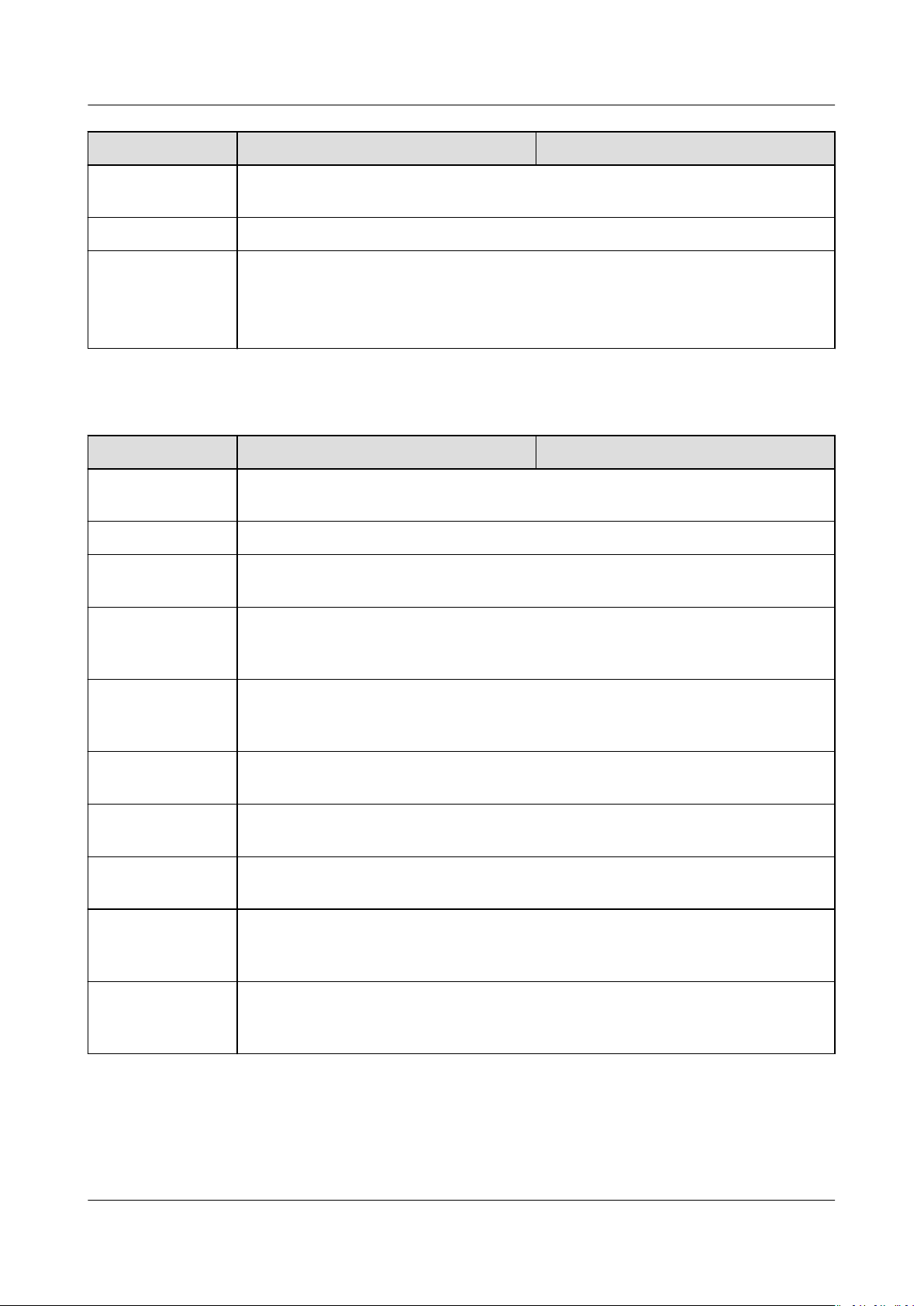
SUN2000-(50KTL-ZHM3, 50KTL-M3)
User Manual 10 Technical Specications
Item SUN2000-50KTL-ZHM3 SUN2000-50KTL-M3
Output voltage
frequency
Power factor 0.8 leading... 0.8 lagging
Maximum total
harmonic
distortion
AC THDi
50 Hz/60 Hz
< 3% under rated conditions
Protection
Item SUN2000-50KTL-ZHM3 SUN2000-50KTL-M3
Overvoltage
category
Input DC switch Supported
Anti-islanding
protection
Output
overcurrent
protection
PV II/AC III
Supported
Supported
Input reverse
connection
protection
PV string fault
detection
DC surge
protection
AC surge
protection
Insulation
resistance
detection
Residual current
monitoring unit
(RCMU)
Supported
Supported
Type II
Type II
Supported
Supported
Issue 03 (2022-08-30) Copyright © Huawei Technologies Co., Ltd. 80
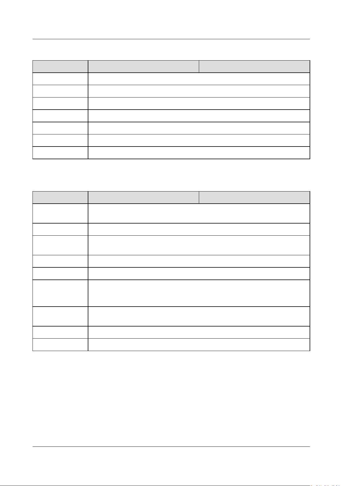
SUN2000-(50KTL-ZHM3, 50KTL-M3)
User Manual 10 Technical Specications
Display and Communication
Item SUN2000-50KTL-ZHM3 SUN2000-50KTL-M3
Display LED indicators; WLAN+app
RS485 Supported
Built-in WLAN Supported
AC MBUS Supported
DC MBUS Supported
AFCI Supported
PID recovery Supported
General
Item SUN2000-50KTL-ZHM3 SUN2000-50KTL-M3
Dimensions (W x
H x D)
Net weight 48 kg
Operating
temperature
Relative humidity 0%–100%
Cooling mode Smart air cooling
Maximum
operating
altitude
Storage
temperature
IP rating IP66
Topology Transformerless
Specications
640 mm x 530 mm x 270 mm
–25°C to +60°C
4000 m
–40°C to +70°C
Issue 03 (2022-08-30) Copyright © Huawei Technologies Co., Ltd. 81
SUN2000-(50KTL-ZHM3, 50KTL-M3)
User Manual 10 Technical Specications
Wireless Communication Parameters
Specications Inverter Built-
in WiFi
Frequency 2400–2483.5
MHz
Protocol
standard
WLAN
802.11b/g/n
WLAN-FE Smart
Dongle
SDongleA-05:
2400–2483.5
MHz
SDongleA-05:
WLAN
802.11b/g/n
4G Smart Dongle
SDongleA-03-CN:
● Supports LTE-FDD: B1/B3/B8.
● Supports LTE-TDD: B38/B39/B40/B41.
● Supports DC-HSPA+/HSPA+/HSPA/
UMTS: B1/B5/B8/B9.
● Supports TD-SCDMA: B34/B39.
● Supports GSM/GPRS/EDGE: 900 MHz/
1800 MHz.
SDongleA-03-EU:
● Supports LTE-FDD: B1/B3/B7/B8/B20.
● Supports LTE-TDD: B38/B40.
● Supports WCDMA/HSDPA/HSUPA/
HSPA+: B1/B8.
● Supports GSM/GPRS/EDGE: 900 MHz/
1800 MHz.
SDongleA-03-CN:
● Supports LTE-FDD (with receive
diversity): B1/B3/B5/B8.
● Supports LTE-TDD (with receive
diversity): B34/B38/B39/B40/B41.
● Supports WCDMA: B1/B5/B8.
● Supports GSM: 900 MHz/1800 MHz.
● Supports digital audio.
SDongleA-03-EU:
● Supports LTE-FDD (with receive
diversity): B1/B3/B7/B8/B20/B28.
● Supports LTE-FDD (with receive
diversity): B38/B40/B41.
● Supports WCDMA: B1/B8.
● Supports GSM: 900 MHz/1800 MHz.
● Supports digital audio.
Issue 03 (2022-08-30) Copyright © Huawei Technologies Co., Ltd. 82

SUN2000-(50KTL-ZHM3, 50KTL-M3)
User Manual 10 Technical Specications
Specications Inverter Built-
in WiFi
Bandwidth 20 MHz/40 MHz
(optional)
WLAN-FE Smart
Dongle
20 MHz/40 MHz
(optional)
4G Smart Dongle
LTE features:
● Supports a maximum of 3GPP R8 nonCA Cat 4 FDD and TDD.
● Supports 1.4 MHz/3 MHz/5 MHz/10
MHz/15 MHz/20 MHz RF bandwidth.
● Supports MIMO in the downlink.
● LTE-FDD: maximum downlink rate of
150 Mbit/s and maximum uplink rate
of 50 Mbit/s
● LTE-TDD: maximum downlink rate of
130 Mbit/s and maximum uplink rate
of 30 Mbit/s
UMTS features:
● Supports 3GPP R7 HSDPA+, HSDPA,
HSUPA, and WCDMA.
● Supports QPSK and 16QAM
modulation.
● HSDPA+: maximum downlink rate of
21 Mbit/s
● HSUPA: maximum uplink rate of 5.76
Mbit/s
● WCDMA: maximum downlink rate of
384 kbit/s and maximum uplink rate
of 384 kbit/s
GSM features:
GPRS:
● Supports GPRS multislot class 12.
● Coding schemes: CS-1, CS-2, CS-3, and
CS-4
● Maximum downlink rate: 85.6 kbit/s;
maximum uplink rate: 85.6 kbit/s
EDGE:
● Supports EDGE multislot class 12.
● Supports GMSK and 8-PSK modulation
and coding schemes.
● Downlink coding format: MCS 1–9
● Uplink coding format: MCS 1–9
● Maximum downlink rate: 236.8 kbit/s;
maximum uplink rate: 236.8 kbit/s
Issue 03 (2022-08-30) Copyright © Huawei Technologies Co., Ltd. 83
SUN2000-(50KTL-ZHM3, 50KTL-M3)
User Manual 10 Technical Specications
Specications Inverter Built-
in WiFi
Maximum
≤ 20 dBm EIRP ≤ 20 dBm EIRP ● Class 4 (33 dBm±2 dB), EGSM900
transmit power
WLAN-FE Smart
Dongle
4G Smart Dongle
frequency band
● Class 1 (30 dBm±2 dB), DCS1800
frequency band
● Class E2 (27 dBm±3 dB), EGSM900 8PSK
● Class E2 (26 dBm±3 dB), DCS1800 8PSK
● Class 3 (24 dBm+1/–3 dB), WCDMA
frequency band
● Class 3 (23 dBm±2 dB), LTE-FDD
frequency band
● Class 3 (23 dBm±2 dB), LTE-TDD
frequency band
Issue 03 (2022-08-30) Copyright © Huawei Technologies Co., Ltd. 84

NO TE
SUN2000-(50KTL-ZHM3, 50KTL-M3)
User Manual A Grid Codes
A Grid Codes
The grid codes are subject to change. The listed codes are for reference only.
No. Grid Code Description SUN2000-50KTL-
ZHM3
1 NB/T 32004 China Golden Sun low-
voltage power grid
2 CHINA-MV480 China medium-voltage
standard power grid
3 CHINA-MV China medium-voltage
standard power grid
4 VDE-AR-N-4105 Germany low-voltage
power grid
5 UTE C 15-712-1(A) France mainland
power grid
6 UTE C 15-712-1(B) France island power
grid
7 UTE C 15-712-1(C) France island power
grid
8 VDE 0126-1-1-GR(A) Greece mainland
power grid
Supported -
Supported -
Supported -
- Supported
- Supported
- Supported
- Supported
- Supported
SUN2000-50KTLM3
9 VDE 0126-1-1-GR(B) Greece island power
grid
10 VDE-AR-N4110 Germany medium-
voltage power grid
(230 V)
11 BDEW-MV Germany medium-
voltage power grid
Issue 03 (2022-08-30) Copyright © Huawei Technologies Co., Ltd. 85
- Supported
- Supported
- Supported

SUN2000-(50KTL-ZHM3, 50KTL-M3)
User Manual A Grid Codes
No. Grid Code Description SUN2000-50KTL-
ZHM3
SUN2000-50KTLM3
12 CEI0-21 Italy power grid - Supported
13 EN50438-CZ Czech Republic power
- Supported
grid
14 RD1699/661 Spain low-voltage
- Supported
power grid
15 RD1699/661-MV480 Spain medium-voltage
- Supported
power grid
16 EN50438-NL Netherlands power
- Supported
grid
17 C10/11 Belgium power grid - Supported
18 IEC61727 IEC 61727 low-voltage
- Supported
grid-tied (50 Hz)
19 CEI0-16 Italy power grid - Supported
20 TAI-PEA Thailand grid-tied
- Supported
standard
21 TAI-MEA Thailand grid-tied
standard
22 VDE-AR-N4110-MV480 Germany medium-
voltage standard
power grid
23 BDEW-MV480 Germany medium-
voltage standard
power grid
24 IEC61727-MV480 IEC 61727 medium-
voltage grid-tied (50
Hz)
25 UTE C 15-712-1-MV480 France island power
grid
26 TAI-PEA-MV480 Thailand medium-
voltage grid-tied (PEA)
27 TAI-MEA-MV480 Thailand medium-
voltage grid-tied
(MEA)
28 EN50438-DK-MV480 Denmark medium-
voltage grid-tied
- Supported
- Supported
- Supported
- Supported
- Supported
- Supported
- Supported
- Supported
29 EN50438-TR-MV480 Turkey medium-
- Supported
voltage power grid
Issue 03 (2022-08-30) Copyright © Huawei Technologies Co., Ltd. 86

SUN2000-(50KTL-ZHM3, 50KTL-M3)
User Manual A Grid Codes
No. Grid Code Description SUN2000-50KTL-
ZHM3
30 EN50438-TR Turkey low-voltage
- Supported
power grid
31 C11/C10-MV480 Belgium medium-
- Supported
voltage power grid
32 Philippines Philippines low-voltage
- Supported
power grid
33 Philippines-MV480 Philippines medium-
- Supported
voltage power grid
34 NRS-097-2-1 South Africa standard
- Supported
power grid
35 NRS-097-2-1-MV480 South Africa medium-
- Supported
voltage standard
power grid
36 IEC61727-60Hz IEC 61727 low-voltage
- Supported
grid-tied (60 Hz)
37 IEC61727-60Hz-MV480 IEC 61727 medium-
- Supported
voltage grid-tied (60
Hz)
SUN2000-50KTLM3
38 ANRE Romania low-voltage
- Supported
power grid
39 PO12.3-MV480 Spain medium-voltage
- Supported
power grid
40 EN50438_IE-MV480 Ireland medium-
- Supported
voltage power grid
41 EN50438_IE Ireland low-voltage
- Supported
power grid
42 CEI0-16-MV480 Italy medium-voltage
- Supported
power grid
43 PO12.3 Spain low-voltage
- Supported
power grid
44 CEI0-21-MV480 Italy medium-voltage
- Supported
power grid
45 EN50549-LV Ireland power grid - Supported
46 EN50549-MV480 Ireland medium-
- Supported
voltage power grid
47 Jordan-Transmission Jordan low-voltage
- Supported
power grid
Issue 03 (2022-08-30) Copyright © Huawei Technologies Co., Ltd. 87

SUN2000-(50KTL-ZHM3, 50KTL-M3)
User Manual A Grid Codes
No. Grid Code Description SUN2000-50KTL-
ZHM3
48 Jordan-Transmission-
MV480
Jordan mediumvoltage power grid
- Supported
SUN2000-50KTLM3
49 ABNT NBR 16149 Brazil power grid - Supported
50 ABNT NBR 16149-
MV480
51 SA_RPPs South Africa low-
Brazil medium-voltage
power grid
- Supported
- Supported
voltage power grid
52 SA_RPPs-MV480 South Africa medium-
- Supported
voltage power grid
53 SAUDI Saudi Arabia power
- Supported
grid
54 SAUDI-MV480 Saudi Arabia power
- Supported
grid
55 VDE-AR-N4120-HV VDE 4120 standard
- Supported
power grid
56 VDE-AR-N4120-HV480 VDE 4120 standard
- Supported
power grid
57 Vietnam Vietnam power grid - Supported
58 Vietnam-MV480 Vietnam power grid - Supported
59 ARGENTINA-MV480 Argentina medium-
- Supported
voltage power grid
60 EN50438-NL-MV480 Netherlands medium-
- Supported
voltage power grid
61 NTS Spain power grid - Supported
62 NTS-MV480 Spain medium-voltage
- Supported
power grid
63 SINGAPORE Singapore low-voltage
- Supported
power grid
64 SINGAPORE-MV480 Singapore medium-
- Supported
voltage power grid
65 C10/11-MV400 Belgium medium-
- Supported
voltage power grid
66 EN50549-PL Poland power grid - Supported
67 EN50549-MV400 Ireland new standard
- Supported
power grid
Issue 03 (2022-08-30) Copyright © Huawei Technologies Co., Ltd. 88
SUN2000-(50KTL-ZHM3, 50KTL-M3)
User Manual A Grid Codes
No. Grid Code Description SUN2000-50KTL-
ZHM3
68 ABNT NBR 16149-
LV127
69 Mexico-LV220 Mexico low-voltage
Brazil low-voltage
power grid
- Supported
- Supported
SUN2000-50KTLM3
power grid
70 Philippines-LV220-50Hz Philippines low-voltage
- Supported
power grid (50 Hz)
71 Philippines-LV220-60Hz Philippines low-voltage
- Supported
power grid (60 Hz)
72 Pakistan Pakistan power grid - Supported
Issue 03 (2022-08-30) Copyright © Huawei Technologies Co., Ltd. 89
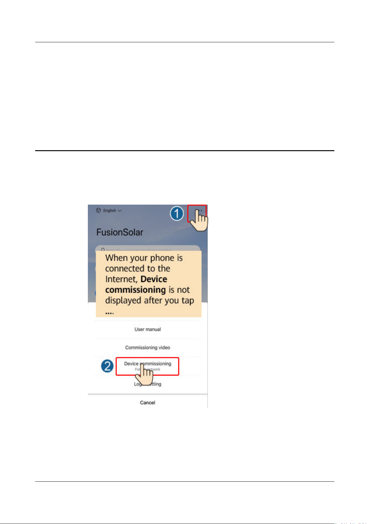
SUN2000-(50KTL-ZHM3, 50KTL-M3)
User Manual B Device Commissioning
B Device Commissioning
Step 1 Access Device commissioning screen.
Figure B-1 Method 1: before login (not connected to the Internet)
Issue 03 (2022-08-30) Copyright © Huawei Technologies Co., Ltd. 90

NO TICE
SUN2000-(50KTL-ZHM3, 50KTL-M3)
User Manual B Device Commissioning
Figure B-2 Method 2: after login (connected to the Internet)
Step 2 Connect to the solar inverter WLAN and log in to the device commissioning screen
as the installer user.
● When connecting to the SUN2000 directly from the mobile phone, keep the
mobile phone visible within 3 meters of the SUN2000 to ensure the
communication quality between the app and SUN2000. The distances are for
reference only and may vary with mobile phones and shielding conditions.
● When connecting the SUN2000 to the WLAN over a router, ensure that the
mobile phone and SUN2000 are in the WLAN coverage of the router and the
SUN2000 is connected to the router.
● The router supports WLAN (IEEE 802.11 b/g/n, 2.4 GHz) and the WLAN signal
reaches the SUN2000.
● The WPA, WPA2, or WPA/WPA2 encryption mode is recommended for routers.
Enterprise-level encryption is not supported (for example, public hotspots
requiring authentication such as airport WLAN). WEP and WPA TKIP are not
recommended because these two encryption modes have serious security
defects. If the access fails in WEP mode, log in to the router and change the
encryption mode of the router to WPA2 or WPA/WPA2.
Issue 03 (2022-08-30) Copyright © Huawei Technologies Co., Ltd. 91

NO TE
SUN2000-(50KTL-ZHM3, 50KTL-M3)
User Manual B Device Commissioning
● Obtain the initial password for connecting to the solar inverter WLAN from the label on
the side of the solar inverter.
● Use the initial password upon rst power-on and change it immediately after login. To
ensure account security, change the password periodically and keep the new password
in mind. Not changing the initial password may cause password disclosure. A password
left unchanged for a long period of time may be stolen or cracked. If a password is lost,
devices cannot be accessed. In these cases, the user is liable for any loss caused to the
PV plant.
● When you access the Device commissioning screen of the SUN2000 for the
you need to manually set the login password because the SUN2000 does not have an
initial login password.
rst time,
----End
Issue 03 (2022-08-30) Copyright © Huawei Technologies Co., Ltd. 92
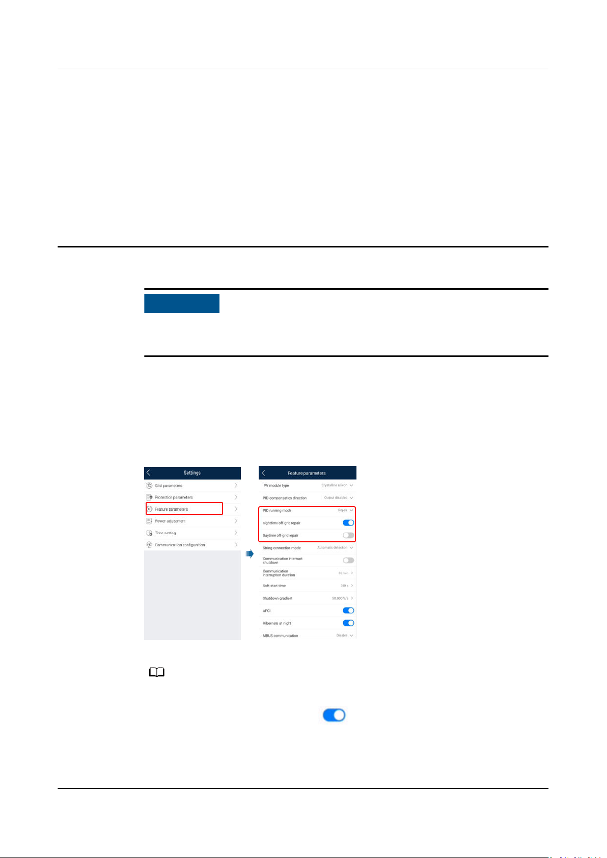
NO TICE
NO TE
SUN2000-(50KTL-ZHM3, 50KTL-M3)
User Manual C Built-in PID Recovery
C Built-in PID Recovery
Ensure that the inverter ground cable is securely connected. Otherwise, the built-in
PID repair function will be aected and electric shocks may occur.
Procedure
Step 1 On the home screen, choose Settings > Feature Parameters and set related
parameters.
Figure C-1 Setting PID suppression parameters
● Set PID running mode to Repair (disabled by default).
● Set Nighttime o-grid repair to (this parameter is displayed when Built-in PID
running mode is set to Repair).
----End
Issue 03 (2022-08-30) Copyright © Huawei Technologies Co., Ltd. 93
 Loading...